JP2009056884A - Vehicle driving force control device - Google Patents
Vehicle driving force control device Download PDFInfo
- Publication number
- JP2009056884A JP2009056884A JP2007224590A JP2007224590A JP2009056884A JP 2009056884 A JP2009056884 A JP 2009056884A JP 2007224590 A JP2007224590 A JP 2007224590A JP 2007224590 A JP2007224590 A JP 2007224590A JP 2009056884 A JP2009056884 A JP 2009056884A
- Authority
- JP
- Japan
- Prior art keywords
- limit value
- friction circle
- circle limit
- mode
- driving force
- Prior art date
- Legal status (The legal status is an assumption and is not a legal conclusion. Google has not performed a legal analysis and makes no representation as to the accuracy of the status listed.)
- Granted
Links
- 238000001514 detection method Methods 0.000 claims description 4
- 238000012937 correction Methods 0.000 abstract description 6
- 238000000034 method Methods 0.000 description 19
- 230000005540 biological transmission Effects 0.000 description 14
- 238000010586 diagram Methods 0.000 description 12
- 230000001133 acceleration Effects 0.000 description 10
- 230000008569 process Effects 0.000 description 9
- 239000000446 fuel Substances 0.000 description 6
- 230000008859 change Effects 0.000 description 4
- 238000012545 processing Methods 0.000 description 4
- 230000000994 depressogenic effect Effects 0.000 description 3
- 230000005484 gravity Effects 0.000 description 3
- 230000033001 locomotion Effects 0.000 description 3
- 238000004891 communication Methods 0.000 description 2
- 239000003112 inhibitor Substances 0.000 description 2
- 238000002347 injection Methods 0.000 description 2
- 239000007924 injection Substances 0.000 description 2
- 238000002485 combustion reaction Methods 0.000 description 1
- 230000000881 depressing effect Effects 0.000 description 1
- 238000002474 experimental method Methods 0.000 description 1
- 230000007246 mechanism Effects 0.000 description 1
- 230000003068 static effect Effects 0.000 description 1
- XLYOFNOQVPJJNP-UHFFFAOYSA-N water Substances O XLYOFNOQVPJJNP-UHFFFAOYSA-N 0.000 description 1
Images


Abstract
Description
本発明は、複数の駆動力特性を有する車両において、車輪のグリップ力を駆動力特性の異なる複数の運転モード毎に適切に保持できるようにした車両の駆動力制御装置に関する。 The present invention relates to a vehicle driving force control device capable of appropriately maintaining a wheel grip force for each of a plurality of driving modes having different driving force characteristics in a vehicle having a plurality of driving force characteristics.
従来、一台の車両で異なる複数の駆動力特性を備え、複数の駆動力特性から、1つの駆動力特性を運転者の好みに応じて選択できるようにしたものが、特許文献1(特許第3930529号公報)等で知られている。 Conventionally, Patent Document 1 (Patent Document 1) includes a plurality of different driving force characteristics in a single vehicle, and one driving force characteristic can be selected according to the driver's preference from the plurality of driving force characteristics. No. 3930529).
又、最近の車両においては、車輪のグリップ力を保持するために、過剰な駆動力を抑制する様々な駆動力制御装置が開発され、実用化されている。例えば特許文献2(特開平10−310042号公報)には、各車輪の摩擦円限界値を求め、この摩擦円限界値を超えない範囲内で、車両の駆動力を制御する技術が開示されている。
ところで、一台で駆動力特性の異なる複数の運転モードを有する車両においては、運転モード毎に運転者のドライバビリティに対する要求は異なる。例えば、サーキット走行時のようにパワフルな走行を実現する駆動力特性を選択した場合、車輪のスリップ率を比較的高めに設定したいという要求がある。逆に、一般道や雨天時のようにそれほどパワーを必要としない走行環境において、経済的な運転を可能にする駆動力特性を選択した場合、スリップ率を比較的低めに設定したいという要求がある。 By the way, in a vehicle having a plurality of operation modes having different driving force characteristics in one vehicle, the driver's requirements for drivability differ for each operation mode. For example, when a driving force characteristic that realizes powerful traveling is selected as in circuit traveling, there is a demand for setting the slip ratio of the wheels to be relatively high. Conversely, when driving force characteristics that enable economical driving are selected in a driving environment that does not require much power, such as on general roads and rainy weather, there is a demand to set the slip ratio relatively low. .
しかし、引用文献2に開示されている技術では、駆動力特性の異なる複数の運転モードを有する車両には対応することができず、一律に設定された摩擦円限界値を超えないように駆動力が制御されてしまうため、運転モード毎にスリップ率を変更することができず、運転者の要求するドライバビリティに応じることができない問題がある。
However, the technique disclosed in the cited
本発明は、上記事情に鑑み、駆動力特性の異なる複数の運転モードを有する車両において、運転モード毎に、運転者の要求するドライバビリティに応じた駆動力を得ることのできる車両の駆動力制御装置を提供することを目的とする。 In view of the above circumstances, the present invention provides a vehicle driving force control capable of obtaining a driving force corresponding to the drivability requested by the driver for each driving mode in a vehicle having a plurality of driving modes having different driving force characteristics. An object is to provide an apparatus.
上記目的を達成するため本発明による第1の車両の駆動力制御装置は、タイヤと路面との間の摩擦力に基づいて摩擦円限界値を設定する摩擦円限界値設定手段と、駆動力特性の異なる複数の運転モードを有し、選択されている1つの該運転モードと運転者の出力要求量を検知する出力要求量検知手段で検知した出力要求量とに基づき要求駆動力を設定する要求駆動力設定手段と、車輪の前後力と横力とに基づきタイヤ合力を設定するタイヤ合力設定手段と、前記摩擦円限界値を、選択されている前記運転モードに応じて補正する摩擦円限界値補正手段と、前記摩擦円限界値補正手段で設定した前記摩擦円限界値に基づき前記要求駆動力設定手段で設定した要求駆動力を制限して駆動系に対する制御量を設定する制御量設定手段とを備えることを特徴とする。 In order to achieve the above object, a driving force control apparatus for a first vehicle according to the present invention includes a frictional circle limit value setting means for setting a frictional circle limit value based on a frictional force between a tire and a road surface, and a driving force characteristic. A request to set a required driving force based on one selected operation mode and an output request amount detected by an output request amount detecting means for detecting the driver's output request amount. Driving force setting means, tire resultant force setting means for setting tire resultant force based on the longitudinal force and lateral force of the wheel, and friction circle limit value for correcting the friction circle limit value according to the selected operation mode And a control amount setting means for setting a control amount for the drive system by limiting the required driving force set by the required driving force setting means based on the friction circle limit value set by the friction circle limit value correcting means. To have Features.
第2の車両の駆動力制御装置は、タイヤと路面との間の摩擦力に基づいて摩擦円限界値を設定する摩擦円限界値設定手段と、駆動力特性の異なる複数の運転モードを有し、選択されている1つの該運転モードと運転者の出力要求量を検知する出力要求量検知手段で検知した出力要求量とに基づき要求駆動力を設定する要求駆動力設定手段と、車輪の前後力と横力とに基づきタイヤ合力を設定するタイヤ合力設定手段と、前記タイヤ合力が前記摩擦円限界値を超えた場合に前記要求駆動力を該摩擦円限界値内に収束させる一次遅れ時定数を、選択されている前記運転モードに応じて可変設定する一次遅れ時定数設定手段と、前記一次遅れ時定数設定手段で設定した一次遅れ時定数に基づき前記要求駆動力設定手段で設定した要求駆動力を制限して駆動系に対する制御量を設定する制御量設定手段とを備えることを特徴とする。 The driving force control device for the second vehicle has friction circle limit value setting means for setting a friction circle limit value based on the friction force between the tire and the road surface, and a plurality of operation modes having different driving force characteristics. Request driving force setting means for setting a required driving force based on the selected one of the driving modes and an output request amount detecting means for detecting the output request amount of the driver; Tire resultant force setting means for setting tire resultant force based on force and lateral force; and a first-order lag time constant for converging the required driving force within the friction circle limit value when the tire resultant force exceeds the friction circle limit value The first-order lag time constant setting means for variably setting according to the selected operation mode, and the requested drive set by the requested drive force setting means based on the first-order lag time constant set by the first-order lag time constant setting means Limit power Characterized in that it comprises a control amount setting means for setting a control amount for the drive system.
本発明によれば、駆動力特性の異なる複数の運転モードを有する車両において、摩擦円限界値の大きさと摩擦円限界値を超えたときの戻り時間の長さとの一方を、運転モード毎に可変設定するようにしたので、運転モード毎に、運転者の要求するドライバビリティに対応する駆動力を得ることができる。 According to the present invention, in a vehicle having a plurality of operation modes having different driving force characteristics, one of the magnitude of the friction circle limit value and the length of the return time when the friction circle limit value is exceeded is variable for each operation mode. Since it is set, the driving force corresponding to the drivability requested by the driver can be obtained for each driving mode.
以下、図面に基づいて本発明の一実施形態を説明する。 Hereinafter, an embodiment of the present invention will be described with reference to the drawings.
[第1実施形態]
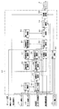
図1〜図7に本発明の第1実施形態を示す。図1に駆動力制御装置の構成図、図2にエンジン制御装置の機能ブロック図を示す。尚、本実施形態では、車両として、センタデファレンシャル付4輪駆動車を例示する。
[First Embodiment]
1 to 7 show a first embodiment of the present invention. FIG. 1 is a configuration diagram of the driving force control device, and FIG. 2 is a functional block diagram of the engine control device. In the present embodiment, a four-wheel drive vehicle with a center differential is exemplified as the vehicle.
図1に示すように、車両には、CAN(Controller Area Network)通信等の車内通信回線16を通じて、メータ制御装置(メータ_ECU)21、エンジン制御装置(E/G_ECU)22、変速機制御装置(T/M_ECU)23等の、車両を制御する演算手段としての制御装置が相互通信可能に接続されている。各ECU21〜23は、マイクロコンピュータ等のコンピュータを主体に構成され、周知のCPU、ROM、RAM、及びEEPROM等の不揮発性記憶手段等を有している。
As shown in FIG. 1, the vehicle is connected to a meter control device (meter_ECU) 21, an engine control device (E / G_ECU) 22, a transmission control device (through a
メータ_ECU21は、運転者前方のインストルメントパネルに設けられているコンビネーションメータ(図示せず)の表示全体を制御すると共に、車両の運転状態を検出するパラメータが入力されて、RAMに一時記憶される。このメータ_ECU21の入力側にモード選択スイッチ10、車体に作用するヨーレートγを検出するヨーレートセンサ11、車体に作用する横加速度Gy(=d2y/dt2)を検出する横加速度センサ12等が接続されている。又、図示しないが出力側には、タコメータ、スピードメータ、水温計、燃料計を代表とする計器類や、各種ウォーニングランプ等、コンビネーションメータに配設されている周知の部品が接続されている。又、モード選択スイッチ10は、エンジンの運転モードDmを選択する外部操作スイッチであり、運転者が任意に操作することができる。本実施形態では、運転モードDmとしてノーマルモードDn、セーブモードDs、パワーモードDpの3種類を備えており、運転者の選択した運転モードDm(=Dn,Ds,Dpの何れか)に対応する運転モード信号が、E/G_ECU22へ出力される。尚、各モードDn,Ds,Dpのエンジン出力特性については後述する。
The
E/G_ECU22は、主にエンジンの運転状態を制御するもので、入力側に、クランク軸等の回転からエンジン回転数Neを検出するエンジン回転数センサ29、エアクリーナの直下流等に配設されて吸入空気量Qを検出する吸入空気量センサ30、アクセルペダルの踏込み量から、運転者の出力要求量であるアクセル開度θaccを検出する、出力要求量検知手段としてのアクセル開度センサ31、吸気通路に介装されて各気筒に供給する吸入空気量を調整する電子制御式スロットル弁(図示せず)の開度を検出するスロットル開度センサ32等、車両及びエンジン運転状態を検出するセンサ類が接続されている。又、E/G_ECU22の出力側に、燃焼室に対して所定に計量された燃料を噴射するインジェクタ36、電子制御式スロットル弁を開閉動作させるスロットルアクチュエータ37、各気筒に配設されている点火プラグに対して点火信号を所定タイミングで出力するイグナイタ38等、エンジン駆動を制御する駆動系が接続されている。
The E /
E/G_ECU22は、入力された各センサ類からの検出信号に基づき、インジェクタ36に対する燃料噴射タイミング、及び燃料噴射パルス幅(パルス時間)を設定すると共に、イグナイタ38に対する最適な点火タイミングを設定する。更に、スロットルアクチュエータ37に対してスロットル開度信号を出力して電子制御式スロットル弁の開度を制御する。
The E /
ところで、E/G_ECU22に設けられている不揮発性記憶手段には、異なる複数のエンジン出力特性(駆動力特性)がマップ形式で格納されている。各エンジン出力特性として、本実施形態ではノーマルモードDn、セーブモードDs、パワーモードDpの3種類の運転モードを備え、不揮発性記憶手段には、この各運転モードDn,Ds,Dpに対応するモードマップMpn,Mps,Mppが格納されている。図7に示すように各モードマップMpn,Mps,Mppは、アクセル開度θaccとエンジン回転数Neとを格子軸とし、各格子点に目標エンジントルクを格納する3次元マップで構成されている。この各モードマップMpn,Mps,Mppは、基本的には、モード選択スイッチ10の操作により選択される。すなわち、E/G_ECU22の後述する要求エンジントルク演算部では、モード選択スイッチ10から出力されるモード選択信号に基づき、運転モードDmとしてノーマルモードDnが選択されている場合、ノーマルモードマップMpnを選択し、セーブモードDsが選択されている場合、セーブモードマップMpsを選択し、又、パワーモードDpが選択されている場合、パワーモードマップMppを選択する。
By the way, a plurality of different engine output characteristics (driving force characteristics) are stored in a map format in the non-volatile storage means provided in the E /
ここで、各モードマップMpn,Mps,Mppに設定されている運転モードDn,Ds,Dp毎のエンジン出力特性について説明する。図7(a)に示すように、ノーマルモードマップMpnには、アクセル開度θaccにほぼ比例して目標エンジントルクが変化する特性に設定されており、又、アクセル開度θaccが全踏付近で、電子制御式スロットル弁が全開となる最大目標エンジントルクに設定されている。 Here, engine output characteristics for each of the operation modes Dn, Ds, and Dp set in each mode map Mpn, Mps, and Mpp will be described. As shown in FIG. 7 (a), the normal mode map Mpn is set to a characteristic in which the target engine torque changes almost in proportion to the accelerator opening degree θacc, and the accelerator opening degree θacc is in the vicinity of all steps. The maximum target engine torque at which the electronically controlled throttle valve is fully opened is set.
又、同図(b)に示すように、セーブモードマップMpsには、上述したノーマルモードマップMpnに格納されているエンジン出力特性に比し、目標エンジントルクの上昇が抑えられており、アクセル開度θaccが全踏であっても電子制御式スロットル弁は全開とはならず、目標エンジントルクの最大値が抑えられている。従って、運転モードDmがセーブモードDsに設定されているときは、アクセル開度θaccの上昇に比しエンジントルクの上昇が抑制され、その結果、アクセルペダルを思い切り踏み込む等のアクセルワークを楽しむことができると共に、経済的な運転を行うことができる。更に、アクセル開度θaccの上昇に比し、目標エンジントルクの上昇が抑えられているため、イージードライブ性と低燃費性との双方をバランス良く両立させることができる。 In addition, as shown in FIG. 5B, the save mode map Mps suppresses the increase in the target engine torque as compared with the engine output characteristics stored in the normal mode map Mpn described above, and the accelerator is opened. Even when the degree θacc is fully depressed, the electronically controlled throttle valve is not fully opened, and the maximum value of the target engine torque is suppressed. Therefore, when the operation mode Dm is set to the save mode Ds, an increase in engine torque is suppressed as compared with an increase in the accelerator opening θacc. As a result, it is possible to enjoy accelerator work such as depressing the accelerator pedal. In addition to being able to operate economically. Furthermore, since the increase in the target engine torque is suppressed as compared with the increase in the accelerator opening θacc, both easy drive performance and low fuel consumption can be achieved in a balanced manner.
又、同図(c)に示すように、パワーモードマップMppには、ほぼ全運転領域でアクセル開度の変化に対し目標エンジントルクが大きく変化するように設定されて、又、アクセル開度θaccが全踏付近では、電子制御式スロットル弁が全開となる最大目標エンジントルクに設定されている。従って、パワーモードDpでは全運転領域において、エンジンの有するポテンシャルを最大限に発揮できるような、パワー重視の目標エンジントルクに設定されている。尚、各運転モードDm(=Dn,Ds、Dp)のエンジン出力特性の詳細については、前述した特許文献1に記述されている。
Further, as shown in FIG. 5C, the power mode map Mpp is set so that the target engine torque changes greatly with respect to the change of the accelerator opening in almost the entire operation region, and the accelerator opening θacc However, the maximum target engine torque at which the electronically controlled throttle valve is fully opened is set near the fully depressed position. Therefore, in the power mode Dp, the target engine torque with emphasis on power is set so as to maximize the potential of the engine in the entire operation region. The details of the engine output characteristics of each operation mode Dm (= Dn, Ds, Dp) are described in
このように、エンジントルク設定手段では、運転者がモード選択スイッチ10を操作して、何れかのモードDn,Ds,Dpを選択すると、対応するモードマップMpn,Mps,Mppが選択され、選択したモードマップMpn,Mps,Mppに基づいて目標エンジントルクを設定する。そして、この目標エンジントルクに基づき電子制御式スロットル弁の弁開度を制御し、駆動力であるエンジン出力を設定する。従って、1つの車両で全く異なる3種類のアクセルレスポンスを楽しむことができる。
Thus, in the engine torque setting means, when the driver operates the
尚、この運転モードDmは、車両の運転条件に応じて自動的に切換えることもできる。例えば、走行中におけるアクセル開度θaccの単位時間当たりの変化量を学習し、登坂走行のようなアクセルペダルが大きく変化する運転領域では、ノーマルモードDnから自動的にパワーモードDpへ切換え、又、市街地走行等のようにアクセル開度θaccの変化量が小さい運転領域では、ノーマルモードDnから自動的にセーブモードDsへ切換えるようにする。 The operation mode Dm can be automatically switched according to the driving conditions of the vehicle. For example, the amount of change per unit time of the accelerator opening θacc during travel is learned, and in an operation region where the accelerator pedal changes greatly, such as uphill travel, the normal mode Dn is automatically switched to the power mode Dp, In an operation region where the amount of change in the accelerator opening θacc is small, such as in urban areas, the normal mode Dn is automatically switched to the save mode Ds.
又、T/M_ECU23は、自動変速機の変速制御を行うもので、入力側にトランスミッション出力軸の回転数等から車速を検出する車速センサ41、セレクトレバー7のセットされているレンジを検出するインヒビタスイッチ42、トルクコンバータに設けられているタービン軸の回転数を検出するタービン回転数センサ43等が接続され、出力側に自動変速機の変速制御を行うコントロールバルブ44、及びロックアップクラッチをロックアップ動作させるロックアップアクチュエータ45が接続されている。このT/M_ECU23では、インヒビタスイッチ42からの信号に基づきセレクトレバーのセットレンジを判定し、Dレンジにセットされているときは、所定の変速パターンに従い、その変速信号をコントロールバルブ44へ出力して変速制御を行う。尚、この変速パターンは、E/G_ECU22で設定されている運転モードDn,Ds,Dpに対応して可変設定される。
Further, the T /
又、ロックアップ条件が満足されたときはロックアップアクチュエータ45にスリップロックアップ信号或いはロックアップ信号を出力し、トルクコンバータの入出力要素間を、コンバータ状態からスリップロックアップ状態、或いはロックアップ状態に切換える。
When the lock-up condition is satisfied, a slip lock-up signal or lock-up signal is output to the lock-up
更に、この運転モードDmは、E/G_ECU22で実行される駆動力制御においても読込まれる。この駆動力制御では、運転モードDmに対応する、車輪の摩擦円限界値μ_Fzi(但し、i=前右輪fr、前左輪fl、後右輪rr、後左輪rl)を各車輪毎に設定する。
Further, the operation mode Dm is read also in the driving force control executed by the E /
図2に示すように、E/G_ECU22は、駆動力制御を実行する機能として、エンジントルク演算部51、要求駆動力設定手段としての要求エンジントルク演算部52、トランスミッション出力トルク演算部53、総駆動力演算部54、前後接地荷重演算部55、左輪荷重比率演算部56、各輪接地荷重演算部57、各輪前後力演算部58、横力推定手段としての各輪横力演算部59、摩擦円限界値設定手段としての各輪摩擦円限界値演算部60、タイヤ合力設定手段としての各輪タイヤ合力演算部61、各輪オーバータイヤ力演算部62、オーバータイヤ力演算部63、オーバートルク演算部64、制御量設定手段としての制御量演算部65を備えている。
As shown in FIG. 2, the E /
エンジントルク演算部51は、スロットル開度センサ32で検出したスロットル開度θthと、エンジン回転数センサ29で検出したエンジン回転数Neとに基づき、エンジントルクマップを補間計算付きで参照し、或いは計算式からエンジントルクTegを演算する。例えばマップには、スロットル開度θthとエンジン回転数Neとをパラメータとして、予め実験などから求めたエンジントルクが格納されており、このマップがE/G_ECU22のROMに固定データとして格納されている。
The engine torque calculation unit 51 refers to or calculates the engine torque map with interpolation calculation based on the throttle opening degree θth detected by the throttle
又、要求エンジントルク演算部52は、メータ_ECU21から出力される運転モード信号、アクセル開度センサ31で検出したアクセル開度θacc、エンジン回転数Neを読込む。そして、先ず、運転モード信号に基づき、選択されている運転モードDm(=Dn,Ds、Dpの何れか)に対応するモードマップ(Mpn,Mps,Mppの何れか)を選択し、選択したモードマップMpn或いはMps或いはMppを、エンジン回転数Neとアクセル開度θaccをパラメータとして補間計算付きで参照して、目標エンジントルクを特定し、この目標エンジントルクを要求エンジントルクTdrvとして設定する。
Further, the requested engine
トランスミッション出力トルク演算部53は、エンジン回転数Neと、T/M_ECU23から出力される変速信号(現在の変速比を示す主変速ギヤ比εi)、及びタービン回転数信号(タービン回転数Nt)と、エンジントルク演算部51で設定したエンジントルクTegとを読込む。そして、先ず、タービン回転数Ntとエンジン回転数Neとの比からトルクコンバータの回転速度比εeを算出する(εe=Nt/Ne)。次いで、この回転速度比εeとトルクコンバータのトルク比とに基づきマップ参照によりトルクコンバータのトルク比εtを設定する。
The transmission output
そして、これらの値に基づき、次式からトランスミッション出力トルクTtを演算する。
Tt=Teg・εt・εi …(1)
又、総駆動力演算部54は、トランスミッション出力トルク演算部53で求めたトランスミッション出力トルクTtを読込み、次式から総駆動力Fxを演算する。
Fx=Tt・η・if/Rt …(2)
ここで、ηは駆動系伝達効率、ifはファイナルギヤ比、Rtはタイヤ半径であり、これらは何れも固定値である。
Based on these values, the transmission output torque Tt is calculated from the following equation.
Tt = Teg · εt · εi (1)
The total driving
Fx = Tt · η · if / Rt (2)
Here, η is drive system transmission efficiency, if is the final gear ratio, Rt is the tire radius, and these are all fixed values.
又、前後接地荷重演算部55は、総駆動力演算部54で算出した総駆動力Fxを読込み、この総駆動力Fxに基づき、前後加速度(d2x/dt2)を、(d2x/dt2)=(Fx/m)から算出する。但し、mは車両質量(固定値)である。そして、この前後加速度(d2x/dt2)に基づき、次式から前輪接地荷重Fzf、及び後輪接地荷重Fzrを演算する。
Fzf=Wf−((m・(d2x/dt2)・h)/L) …(3)
Fzr=W−Fzf …(4)
尚、Wfは前輪静加重、hは重心高さ、Lはホイールベース、Wは車両重量(=m・G、但し、Gは重力加速度)であり、これらは何れも固定値である。
The front / rear ground
Fzf = Wf − ((m · (d 2 x / dt 2 ) · h) / L) (3)
Fzr = W−Fzf (4)
Wf is the front wheel static load, h is the height of the center of gravity, L is the wheel base, W is the vehicle weight (= m · G, where G is the gravitational acceleration), and these are fixed values.
又、左輪荷重比率演算部56は、T/M_ECU23から出力される横加速度信号(横加速度Gy)を読込み、次式から左輪荷重比率WR_lを算出する。
WR_l=0.5−(Gy/G)・(h/Ltred) …(5)
尚、Ltredは前輪と後輪のトレッド平均値で、固定値である。
The left wheel load
WR_l = 0.5- (Gy / G). (H / Ltred) (5)
In addition, Ltred is a tread average value of the front wheel and the rear wheel, and is a fixed value.
又、各輪接地荷重演算部57は、前後接地荷重演算部55で求めた前輪接地荷重Fzf、後輪接地荷重Fzr、及び、左輪荷重比率演算部56で算出した左輪荷重比率WR_lを読込み、次式から、各車輪の接地荷重Fzi(但し、i=前左輪f_l、前右輪f_r、後左輪r_l、後右輪r_r)を演算する。
Fzf_l=Fzf・WR_l …(6)
Fzf_r=Fzf・(1−WR_l)…(7)
Fzr_l=Fzr・WR_l …(8)
Fzr_r=Fzr・(1−WR_l) …(9)
各輪前後力演算部58は、図示しないセンタデファレンシャル装置で設定したセンタデファレンシャルの差動を制限するLSD(Limited Slip Differential)クラッチに対する締結トルクTLSDを読込み、又、トランスミッション出力トルク演算部53で求めたトランスミッション出力トルクTtと、総駆動力演算部54で求めた総駆動力Fxと、前後接地荷重演算部55で求めた前輪接地荷重Fzfとを読込む。
Each wheel ground
Fzf_l = Fzf · WR_l (6)
Fzf_r = Fzf · (1−WR_l) (7)
Fzr_l = Fzr · WR_l (8)
Fzr_r = Fzr · (1−WR_l) (9)
Each wheel longitudinal force calculation unit 58 reads an engagement torque TLSD for an LSD (Limited Slip Differential) clutch that limits the differential of the center differential set by a center differential device (not shown), and is obtained by the transmission output
そして、各車輪の前後力Fxi(但し、i=前左輪f_l、前右輪f_r、後左輪r_l、後右輪r_r)を演算する。各車輪の前後力Fxiを演算するに際しては、先ず、前輪荷重配分率WR_fを次式から算出する。
WR_f=Fzf/W …(10)
次に、最小前輪前後トルクTfminと最大前輪前後トルクTfmaxを次式から算出する。
Tfmin=Tt・Rf_cd−TLSD(≧0) …(11)
Tfmax=Tt・Rf_cd+TLSD(≧0) …(12)
尚、Rf_cdは、センタデファレンシャル装置のベーストルク配分である。
Then, the longitudinal force Fxi (where i = front left wheel f_l, front right wheel f_r, rear left wheel r_l, rear right wheel r_r) is calculated. When calculating the longitudinal force Fxi of each wheel, first, the front wheel load distribution ratio WR_f is calculated from the following equation.
WR_f = Fzf / W (10)
Next, the minimum front wheel longitudinal torque Tfmin and the maximum front wheel longitudinal torque Tfmax are calculated from the following equations.
Tfmin = Tt · Rf_cd−TLSD (≧ 0) (11)
Tfmax = Tt · Rf_cd + TLSD (≧ 0) (12)
Rf_cd is the base torque distribution of the center differential device.
次いで、最小前輪前後力Fxfminと最大前輪前後力Fxfmaxを次式から算出する。
Fxfmin=Tfmin・η・if/Rt …(13)
Fxfmax=Tfmax・η・if/Rt …(14)
そして、これらの値に基づき以下のように状態判定を行う。
・WR_f≦Fxfmin/Fxの場合、後輪側に差動制限トルクが増加されているとし、判定値I=1とする。
・WR_f≧Fxfmax/Fxの場合、前輪側に差動制限トルクが増加されているとし、判定値I=3とする。
・上記以外の場合は通常時と判定して、判定値I=2とする。
Next, the minimum front wheel longitudinal force Fxfmin and the maximum front wheel longitudinal force Fxfmax are calculated from the following equations.
Fxfmin = Tfmin · η · if / Rt (13)
Fxfmax = Tfmax · η · if / Rt (14)
Based on these values, state determination is performed as follows.
When WR_f ≦ Fxfmin / Fx, it is assumed that the differential limiting torque is increased on the rear wheel side, and the determination value I = 1.
When WR_f ≧ Fxfmax / Fx, it is assumed that the differential limiting torque is increased on the front wheel side, and the determination value I = 3.
In cases other than the above, it is determined as normal time, and the determination value I = 2.
次いで、この判定値Iに応じた前輪前後力Fxfを次式から算出する。 Next, the front wheel longitudinal force Fxf corresponding to the determination value I is calculated from the following equation.
・I=1の場合
Fxf=Tfmin・η・if/Rt …(15)
・I=2の場合
Fxf=Fx・WR_f …(16)
・I=3の場合
Fxf=Fxfmax・η・if/Rt …(17)
そして、(15)〜(17)式で演算した前輪前後力Fxfに基づき、後輪前後力Fxrを次式から算出する。
Fxr=Fx−Fxf …(18)
以上の前輪前後力Fxf、及び、後輪前後力Fxrを用いて、次式から各車輪の前後力Fxiをそれぞれ算出する。
When I = 1 Fxf = Tfmin · η · if / Rt (15)
When I = 2 Fxf = Fx.WR_f (16)
When I = 3 Fxf = Fxfmax · η · if / Rt (17)
Then, based on the front wheel longitudinal force Fxf calculated by the equations (15) to (17), the rear wheel longitudinal force Fxr is calculated from the following equation.
Fxr = Fx−Fxf (18)
Using the front wheel longitudinal force Fxf and the rear wheel longitudinal force Fxr, the longitudinal force Fxi of each wheel is calculated from the following equation.
Fxf_l=Fxf/2 …(19)
Fxf_r=Fxf_l …(20)
Fxr_l=Fxr/2 …(21)
Fxr_r=Fxr_l …(22)
尚、本実施形態で示した各輪前後力の演算は、あくまで一例であり、車両の駆動形式・駆動機構等により適宜、選択することができる。
Fxf_l = Fxf / 2 (19)
Fxf_r = Fxf_l (20)
Fxr_l = Fxr / 2 (21)
Fxr_r = Fxr_l (22)
Note that the calculation of the front-rear force of each wheel shown in the present embodiment is merely an example, and can be appropriately selected depending on the drive type / drive mechanism of the vehicle.
又、各輪横力演算部59は、横加速度Gyとメータ_ECU21から出力されるヨーレート信号(ヨーレートγ)と、左輪荷重比率演算部56で求めた左輪荷重比率WR_lとを読込む。そして、先ず、次式から、前輪横力Fyfと後輪横力Fyrとを演算する。
Each wheel lateral
Fyf=(Iz・(dγ/dt)+m・Gy・Lr)/L …(23)
Fyr=(−Iz・(dγ/dt)+m・Gy・Lf)/L …(24)
ここで、Izは車両のヨー慣性モーメント、Lrは後軸−重心間距離、Lfは前軸−重心間距離であり、何れも固定値である。
Fyf = (Iz · (dγ / dt) + m · Gy · Lr) / L (23)
Fyr = (− Iz · (dγ / dt) + m · Gy · Lf) / L (24)
Here, Iz is the yaw moment of inertia of the vehicle, Lr is the distance between the rear axis and the center of gravity, and Lf is the distance between the front axis and the center of gravity, both of which are fixed values.
次いで、この前輪横力Fyf、後輪横力Fyrに基づき次式から、各車輪の横力Fyi(但し、i=前左輪f_l、前右輪f_r、後左輪r_l、後右輪r_r)を算出する。 Next, the lateral force Fyi of each wheel (where i = front left wheel f_l, front right wheel f_r, rear left wheel r_l, rear right wheel r_r) is calculated from the following formula based on the front wheel lateral force Fyf and the rear wheel lateral force Fyr. To do.
Fyf_l=Fyf・WR_l …(25)
Fyf_r=Fyf・(1−WR_l) …(26)
Fyr_l=Fyr・WR_l …(27)
Fyr_r=Fyr・(1−WR_l) …(28)
各輪摩擦円限界値演算部60は、各車輪の摩擦円限界値μ_Fzi(但し、i=前左輪f_l、前右輪f_r、後左輪r_l、後右輪r_r)を算出する。この各輪摩擦円限界値演算部60における各車輪の摩擦円限界値μ_Fziの算出は、図3に示す摩擦円限界値演算ルーチンにおいて求められる。
Fyf_l = Fyf · WR_l (25)
Fyf_r = Fyf. (1-WR_l) (26)
Fyr_l = Fyr · WR_l (27)
Fyr_r = Fyr · (1-WR_l) (28)
Each wheel friction circle limit
このルーチンでは、先ず、ステップS1で路面摩擦係数μを読込む。この路面摩擦係数μは、E/G_ECU22に設けられている図示しない路面μ演算部において求められ、各輪摩擦円限界値演算部60に対し、路面摩擦係数信号として出力される。ここで、路面μ演算部における路面摩擦係数μの設定方法について簡単に説明する。この路面摩擦係数μの設定方法は、本出願人が、先に提出した特開平8−2274号公報に開示されている技術に基づいて行う。すなわち、先ず、舵角、車速、実ヨーレートにより車両の横運動の運動方程式に基づき前後輪のコーナリングパワを非線形域に拡張して推定する。そして、高μ路(μ=1.0)での前後輪の等価コーナリングパワに対する推定した前後輪のコーナリングパワの比から路面摩擦係数μを設定する。尚、路面摩擦係数μの設定方法は、同公報に開示されている技術に限定されるものではなく、他の方法、例えば本出願人が提出した特開2000−71968号公報に開示されている開示する方法で求めても良く、或いは各車輪に発生するすべり率から各輪毎に求めても良い。
In this routine, first, the road surface friction coefficient μ is read in step S1. The road surface friction coefficient μ is determined by a road surface μ calculation unit (not shown) provided in the E /
次いで、ステップS2へ進み、各輪接地荷重演算部57から出力される各車輪の接地荷重Fzi(但し、i=前左輪f_l、前右輪f_r、後左輪r_l、後右輪r_r)を読込む。そして、ステップS3で、路面摩擦係数μと各車輪の接地荷重Fziとに基づき、次式から各車輪の標準摩擦円限界値Sμ_Fzi(但し、i=前左輪f_l、前右輪f_r、後左輪r_l、後右輪r_r)を設定する。
Sμ_Fzi=μ・Fzi …(29)
その後、ステップS4へ進み、メータ_ECU21から出力される運転モード信号(運転モードDm)を読込み、ステップS5,S6で、現在、設定されている運転モードDmを調べる。そして、Dm=Dnの現在の運転モードがノーマルモードDnのときは、ステップS5からステップS7へ進み、標準摩擦円限界値Sμ_Fzi(但し、i=前左輪f_l、前右輪f_r、後左輪r_l、後右輪r_r)で、摩擦円限界値μ_Fzi(但し、i=前左輪f_l、前右輪f_r、後左輪r_l、後右輪r_r)を設定して(μ_Fzi←Sμ_Fzi)、ルーチンを抜ける。尚、ステップS7での処理が、本発明の摩擦円限界値補正手段に対応している。
Next, the process proceeds to step S2, and the ground load Fzi (i = front left wheel f_l, front right wheel f_r, rear left wheel r_l, rear right wheel r_r) output from each wheel ground
Sμ_Fzi = μ · Fzi (29)
Then, it progresses to step S4, the operation mode signal (operation mode Dm) output from meter_ECU21 is read, and the operation mode Dm currently set is investigated by step S5, S6. When the current operation mode of Dm = Dn is the normal mode Dn, the process proceeds from step S5 to step S7, and the standard friction circle limit value Sμ_Fzi (where i = front left wheel f_l, front right wheel f_r, rear left wheel r_l, At the rear right wheel r_r), the friction circle limit value μ_Fzi (where i = front left wheel f_l, front right wheel f_r, rear left wheel r_l, rear right wheel r_r) is set (μ_Fzi ← Sμ_Fzi), and the routine is exited. Note that the processing in step S7 corresponds to the frictional circle limit value correcting means of the present invention.
又、Dm=Dsの現在の運転モードがセーブモードDsのときは、ステップS5、ステップS6を経てステップS8へ進み、標準摩擦円限界値Sμ_Fziにセーブモード補正値αs(但し、0.5<αs<1.0)を乗算した値で、摩擦円限界値μ_Fziを設定して(μ_Fzi←αs・Sμ_Fzi)、ルーチンを抜ける。 Further, when the current operation mode of Dm = Ds is the save mode Ds, the process proceeds to step S8 through step S5 and step S6, and the save mode correction value αs (where 0.5 <αs <1.0 is added to the standard friction circle limit value Sμ_Fzi). ) Is set to the friction circle limit value μ_Fzi (μ_Fzi ← αs · Sμ_Fzi), and the routine is exited.
又、Dm=Dpの現在の運転モードがパワーモードDpのときは、ステップS5、ステップS6を経てステップS9へ進み、標準摩擦円限界値Sμ_Fziにパワーモード補正値αp(但し、1.0<αp<1.5)を乗算した値で、摩擦円限界値μ_Fziを設定して(μ_Fzi←αp・Sμ_Fzi)、ルーチンを抜ける。 Further, when the current operation mode of Dm = Dp is the power mode Dp, the process proceeds to step S9 through step S5 and step S6, and the power mode correction value αp (where 1.0 <αp <1.5 is set to the standard friction circle limit value Sμ_Fzi). ) Is set to the friction circle limit value μ_Fzi (μ_Fzi ← αp · Sμ_Fzi), and the routine is exited.
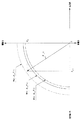
図4に示すように、摩擦円限界値μ_Fziは、車輪がグリップ力を保持した状態で車両の運動性能を制御できる限界を表す円の半径であり、摩擦円限界値μ_Fziの大きさはタイヤと路面との間に生じる摩擦力の最大値を表している。又、タイヤの摩擦力は、進行方向(駆動力又は制動力)の力と横方向(右方向又は左方向)の摩擦力との合成力であり、何れかの方向の摩擦力が100%、すなわち摩擦円限界値μ_Fziの大きさに一致した場合、他方向の摩擦力はゼロになる。尚、制動力は駆動力と逆方向になる。 As shown in FIG. 4, the friction circle limit value μ_Fzi is a radius of a circle representing a limit that can control the motion performance of the vehicle with the wheel holding the gripping force. The size of the friction circle limit value μ_Fzi is It represents the maximum value of the friction force generated between the road surface. The frictional force of the tire is a combined force of the force in the traveling direction (driving force or braking force) and the frictional force in the lateral direction (right direction or left direction), and the frictional force in either direction is 100%. That is, when it coincides with the size of the friction circle limit value μ_Fzi, the frictional force in the other direction becomes zero. The braking force is in the opposite direction to the driving force.
本実施形態では、この摩擦円限界値μ_Fziを、運転モードDm(=Dn,Ds、Dp)毎に設定されており、ノーマルモードDn選択時に設定される摩擦円限界値μ_Fziを標準値とし、セーブモードDs選択時に設定される摩擦円限界値μ_Fziを、標準値よりも小さい値とし、パワーモードDp選択時に設定される摩擦円限界値μ_Fziを、標準値よりも大きな値としている。又、図5に示すように、この摩擦円限界値μ_Fziは各車輪毎に設定され、後述するように、各車輪毎のタイヤ合力F_i(但し、i=前左輪fl、前右輪fr、後左輪rl、後右輪rr)と比較される。 In this embodiment, the friction circle limit value μ_Fzi is set for each operation mode Dm (= Dn, Ds, Dp), and the friction circle limit value μ_Fzi set when the normal mode Dn is selected is set as a standard value, and saved. The friction circle limit value μ_Fzi set when the mode Ds is selected is smaller than the standard value, and the friction circle limit value μ_Fzi set when the power mode Dp is selected is larger than the standard value. Further, as shown in FIG. 5, the frictional circle limit value μ_Fzi is set for each wheel, and, as will be described later, tire resultant force F_i for each wheel (where i = front left wheel fl, front right wheel fr, rear Compared with left wheel rl and rear right wheel rr).
又、各輪タイヤ合力演算部61は、各輪前後力演算部58で求めた各車輪の前後力Fxi)と、各輪横力演算部59で求めた各車輪の横力Fyi(但し、i=前左輪f_l、前右輪f_r、後左輪r_l、後右輪r_r)とに基づき、次式に示す二乗和平方根から各車輪のタイヤ合力F_iを算出する(図6参照)。
F_i=(Fxi2+Fyi2)1/2 …(30)
又、各輪オーバータイヤ力演算部62は、各輪摩擦円限界値演算部60で求めた各車輪の摩擦円限界値μ_Fziと、各輪タイヤ合力演算部61で求めた各車輪のタイヤ合力F_iとに基づき、次式から各車輪のオーバータイヤ力ΔF_iを算出する。
ΔF_i=F_i−μ_Fzi …(31)
図5に示すように、オーバータイヤ力ΔF_iは、タイヤ合力F_iと摩擦円限界値μ_Fziとの単純な差分であるため、タイヤ合力F_iが摩擦円限界値μ_Fzi内の場合、換言すれば、摩擦円限界値μ_Fziに対してタイヤ合力F_iに余裕がある場合は、負値となる。又、このときの摩擦円限界値μ_Fziは、運転モードDm(=Dn,Ds,Dpの何れか)毎に設定されているため、図6に示すように、例えばノーマルモードDn時の摩擦円限界値μ_Fziではオーバータイヤ力ΔF_iが正値(F_i>μ_Fzi)であっても、パワーモードDp時の摩擦円限界値μ_Fziではオーバータイヤ力ΔF_iが負値(F_i<μ_Fzi)となる場合がある。或いは、ノーマルモードDn時の摩擦円限界値μ_Fziではオーバータイヤ力ΔF_iが負値(F_i<μ_Fzi)であっても、セーブモードDs時の摩擦円限界値μ_Fziではオーバータイヤ力ΔF_iが正値(F_i>μ_Fzi)となる場合もある。
Further, each wheel tire resultant
F_i = (Fxi 2 + Fyi 2 ) 1/2 (30)
Further, each wheel over-tyre
ΔF_i = F_i−μ_Fzi (31)
As shown in FIG. 5, the over-tyre force ΔF_i is a simple difference between the tire resultant force F_i and the friction circle limit value μ_Fzi, and therefore when the tire resultant force F_i is within the friction circle limit value μ_Fzi, in other words, the friction circle When the tire resultant force F_i has a margin with respect to the limit value μ_Fzi, the value is negative. Since the friction circle limit value μ_Fzi at this time is set for each operation mode Dm (= Dn, Ds, or Dp), as shown in FIG. 6, for example, the friction circle limit in the normal mode Dn is used. Even if the overtire force ΔF_i is a positive value (F_i> μ_Fzi) at the value μ_Fzi, the overtire force ΔF_i may be a negative value (F_i <μ_Fzi) at the friction circle limit value μ_Fzi in the power mode Dp. Alternatively, even if the overtire force ΔF_i is a negative value (F_i <μ_Fzi) in the friction circle limit value μ_Fzi in the normal mode Dn, the overtire force ΔF_i is a positive value (F_i) in the friction circle limit value μ_Fzi in the save mode Ds. > Μ_Fzi).
又、オーバータイヤ力演算部63は、各輪オーバータイヤ力演算部62で求めた各車輪のオーバータイヤ力ΔF_i(但し、i=前左輪fl、前右輪fr、後左輪rl、後右輪rr)の総和を求め、この値をオーバータイヤ力Foverとして設定する。
Fover=ΔF_fl+ΔF_fr+ΔF_rl+ΔF_rr …(32)
例えば、全ての車輪のオーバータイヤ力ΔF_iの平均が負値の場合、オーバータイヤ力Foverは負値となり、この平均が正値の場合、オーバータイヤ力Foverは正値となる。又、この場合、各車輪のオーバータイヤ力ΔF_i(i=前左輪fl、前右輪fr、後左輪rl、後右輪rr)の中で、最も大きな値を示すものをオーバータイヤ力Foverとして設定するようにしても良い。或いは各車輪のオーバータイヤ力ΔF_iの平均値をオーバータイヤ力Foverとして設定しても良い。
Further, the over-tyre force calculating unit 63 calculates the over-tyre force ΔF_i of each wheel obtained by each wheel over-tyre force calculating unit 62 (where i = front left wheel fl, front right wheel fr, rear left wheel rl, rear right wheel rr ), And this value is set as the overtire force Fover.
Fover = ΔF_fl + ΔF_fr + ΔF_rl + ΔF_rr (32)
For example, when the average over tire force ΔF_i of all the wheels is a negative value, the over tire force Fover is a negative value. When the average is a positive value, the over tire force Fover is a positive value. In this case, the over tire force ΔF_i (i = front left wheel fl, front right wheel fr, rear left wheel rl, rear right wheel rr) having the largest value is set as the over tire force Fover. You may make it do. Alternatively, the average value of the over tire force ΔF_i of each wheel may be set as the over tire force Fover.
又、オーバートルク演算部64は、オーバータイヤ力演算部63で求めたオーバータイヤ力Foverに基づき、次式からオーバートルクToverを演算する。
Tover=Fover・Rt/εt/εi/η/if …(33)
ここで、ηは駆動系伝達効率、ifはファイナルギヤ比、Rtはタイヤ半径であり、これらは何れも固定値である。又、εtはトルクコンバータのトルク比であり、トルクコンバータの回転速度比e(=Nt/Ne)とトルクコンバータのトルク比とに基づきマップ参照により求める。尚、オーバートルクToverが正値(負値)の場合、オーバータイヤ力Foverも正値(負値)となる。
The
Tover = Fover · Rt / εt / εi / η / if (33)
Here, η is drive system transmission efficiency, if is the final gear ratio, Rt is the tire radius, and these are all fixed values. Further, εt is the torque ratio of the torque converter, and is obtained by referring to the map based on the rotational speed ratio e (= Nt / Ne) of the torque converter and the torque ratio of the torque converter. When the overtorque Tover is a positive value (negative value), the overtire force Fover is also a positive value (negative value).
そして、制御量演算部65は、要求エンジントルク演算部52で求めた要求エンジントルクTdrvと、オーバートルク演算部64で求めたオーバートルクToverとに基づき、次式から新たな駆動力制御量である出力トルクTreqを演算する。
・Tover<0、すなわち、摩擦円限界値μ_Fziよりもタイヤ合力F_iが小さい場合、
Treq=Tdrv …(34)
・Tover≧0、すなわち、摩擦円限界値μ_Fziよりもタイヤ合力F_iが大きい場合、
Treq=(Tdrv−Tover) …(35)
そして、この出力トルクTreqを、電子制御式スロットル弁を駆動するスロットルアクチュエータへ出力する。その結果、要求エンジントルクTdrvは、常に摩擦円限界値μ_Fzi内に収まるように制限される。その際、運転モードDmがセーブモードDsに設定されている場合、図4に破線で示すように摩擦円限界値μ_Fziが、ノーマルモードDn時の摩擦円限界値μ_Fziよりもセーブモード補正値αsの割合分だけ、見かけ上、縮小される。そのため、駆動力の抑制されたセーブモードDsを好む運転者は、アクセルペダルを思い切り踏み込んでも、車輪のグリップ力が充分に保持されて滑りが発生しないので、運転者の要求に応じたドライバビリティを得ることができる。
The control
・ Tover <0, that is, when the tire resultant force F_i is smaller than the friction circle limit value μ_Fzi,
Treq = Tdrv (34)
・ Tover ≧ 0, that is, when the tire resultant force F_i is larger than the friction circle limit value μ_Fzi,
Treq = (Tdrv−Tover) (35)
The output torque Treq is output to a throttle actuator that drives an electronically controlled throttle valve. As a result, the required engine torque Tdrv is always limited to be within the friction circle limit value μ_Fzi. At this time, when the operation mode Dm is set to the save mode Ds, the friction circle limit value μ_Fzi is smaller than the friction circle limit value μ_Fzi in the normal mode Dn as shown by the broken line in FIG. It is reduced in appearance by the proportion. Therefore, even if the driver prefers the save mode Ds in which the driving force is suppressed, even if the accelerator pedal is fully depressed, the grip force of the wheel is sufficiently maintained and no slipping occurs, so the drivability according to the driver's request is provided. Obtainable.
一方、運転モードDmがパワーモードDpに設定されている場合、図4に一点鎖線で示すように摩擦円限界値μ_Fziが、ノーマルモードDn時の摩擦円限界値μ_Fziよりもパワーモード補正値αpの割合分だけ見かけ上、拡大されるため、多少の滑りは発生するが、パワーを重視した運転を好む運転者の要求に応じたドライバビリティを得ることができる。 On the other hand, when the operation mode Dm is set to the power mode Dp, the friction circle limit value μ_Fzi is greater than the friction circle limit value μ_Fzi in the normal mode Dn, as shown by a one-dot chain line in FIG. Since it is enlarged by the proportion, it is possible to obtain drivability according to the demand of the driver who prefers driving with emphasis on power, although some slip occurs.
[第2実施形態]
図8〜図11に本発明の第2実施形態を示す。図8はエンジン制御装置の機能ブロック図である。上述した第1実施形態では摩擦円限界値μ_Fziを、エンジンの運転モードDmに応じて可変設定するようにしたが、本実施形態では摩擦円限界値μ_Fziは標準値とし、タイヤ合力F_iが摩擦円限界値μ_Fziを越えるまで、要求エンジントルクTdrvは制限せず、タイヤ合力F_iが摩擦円限界値μ_Fziを越えたときから、エンジンの運転モードDm(=Dn,Ds、Dpの何れか)毎に設定されている一次遅れ時定数T(=Tn,Ts,Tp)で、タイヤ合力F_iを摩擦円限界値μ_Fziへ戻すようにしたものである。
[Second Embodiment]
8 to 11 show a second embodiment of the present invention. FIG. 8 is a functional block diagram of the engine control apparatus. In the first embodiment described above, the friction circle limit value μ_Fzi is variably set according to the engine operation mode Dm. However, in this embodiment, the friction circle limit value μ_Fzi is a standard value, and the tire resultant force F_i is the friction circle. The required engine torque Tdrv is not limited until the limit value μ_Fzi is exceeded, and is set for each engine operation mode Dm (= Dn, Ds, Dp) from when the tire resultant force F_i exceeds the friction circle limit value μ_Fzi. The tire resultant force F_i is returned to the friction circle limit value μ_Fzi with the first-order lag time constant T (= Tn, Ts, Tp).
図8に示すエンジン制御装置の機能ブロック図において、上述した第1実施形態の処理と異なる処理を実施する演算部は、各輪摩擦円限界値演算部60と制御量演算部65であり、その他の演算部51〜59,61〜64では、第1実施形態と共通した処理が実行される。従って、第1実施形態と共通した処理を行う演算部についての説明は省略する。
In the functional block diagram of the engine control device shown in FIG. 8, the calculation units that perform processing different from the processing of the first embodiment described above are each wheel friction circle limit
各輪摩擦円限界値演算部60で算出される各車輪の摩擦円限界値μ_Fzi(但し、i=前左輪f_l、前右輪f_r、後左輪r_l、後右輪r_r)は、図9に示す摩擦円限界値演算ルーチンに従って求められる。
The friction circle limit values μ_Fzi (where i = front left wheel f_l, front right wheel f_r, rear left wheel r_l, rear right wheel r_r) calculated by the wheel friction circle limit
このルーチンでは、先ず、ステップS11で路面摩擦係数μを読込む。尚、路面摩擦係数μの求め方については既述したので説明を省略する。 In this routine, first, the road surface friction coefficient μ is read in step S11. Since the method for obtaining the road surface friction coefficient μ has already been described, the description thereof will be omitted.
次いで、ステップS12で、各輪接地荷重演算部57から出力される各車輪の接地荷重Fzi(但し、i=前左輪f_l、前右輪f_r、後左輪r_l、後右輪r_r)を読込む。そして、ステップS13で、路面摩擦係数μと各車輪の接地荷重Fziとに基づき、次式から各車輪の摩擦円限界値μ_Fzi(但し、i=前左輪f_l、前右輪f_r、後左輪r_l、後右輪r_r)を設定して、ルーチンを抜ける。
μ_Fzi=μ・Fzi …(29’)
又、制御量演算部65では、図10に示す制御量演算ルーチンに従い、エンジンの出力トルクTreqが算出される。このルーチンでは、先ず、ステップS21で、オーバートルク演算部64で求めたオーバートルクToverが正値を示しているか否かを調べ、負値の場合(Tover<0)は、ステップS22へ分岐し、要求エンジントルク演算部52で求めた要求エンジントルクTdrvで、出力トルクTreqを設定して(Treq←Tdrv)、ルーチンを抜ける。
Next, in step S12, the ground load Fzi (i = front left wheel f_l, front right wheel f_r, rear left wheel r_l, rear right wheel r_r) output from each wheel ground
μ_Fzi = μ · Fzi (29 ′)
Further, the
又、オーバートルクToverが正値を示している場合(Tover≧0)、ステップS23へ進み、現在設定されているエンジンの運転モードDm(=Dn,Ds,Dpの何れか)を読込む。そして、ステップS24で、設定されている運転モードDm(=Dn,Ds,Dpの何れか)に対応する一次遅れ時定数Tを設定する。図11に示すように、一次遅れ時定数Tは、運転モードDmがノーマルモードDnに設定されている際のノーマルモード時定数Tnを標準値とし、運転モードDmがセーブモードDsに設定されている際のセーブモード時定数Tsが、ノーマルモード時定数Tnよりも短く設定され、又、運転モードDmがパワーモードDpに設定されている際のパワーモード時定数Tpが、ノーマルモード時定数Tnよりも長く設定されている(Ts<Tn<Tp)。 If the overtorque Tover shows a positive value (Tover ≧ 0), the process proceeds to step S23, and the currently set engine operation mode Dm (= Dn, Ds, or Dp) is read. In step S24, a first-order lag time constant T corresponding to the set operation mode Dm (= Dn, Ds, or Dp) is set. As shown in FIG. 11, the first-order lag time constant T has the normal mode time constant Tn when the operation mode Dm is set to the normal mode Dn as a standard value, and the operation mode Dm is set to the save mode Ds. The save mode time constant Ts is set shorter than the normal mode time constant Tn, and the power mode time constant Tp when the operation mode Dm is set to the power mode Dp is smaller than the normal mode time constant Tn. It is set long (Ts <Tn <Tp).
その後、ステップS25へ進み、次式から出力トルクTreqを演算する。
Treq←(k/(1+T・s))・(Tdrv−Tover)…(35’)
ここで、Kは比例定数で、本実施形態ではK=1に設定されている。又、sはラプラス演算子である。尚、ステップS24,S25での処理が、本発明の一次遅れ時定数設定手段に対応している。
Thereafter, the process proceeds to step S25, and the output torque Treq is calculated from the following equation.
Treq ← (k / (1 + T · s)) · (Tdrv−Tover) (35 ′)
Here, K is a proportionality constant and is set to K = 1 in this embodiment. S is a Laplace operator. The processes in steps S24 and S25 correspond to the first-order lag time constant setting means of the present invention.
そして、この出力トルクTreqを、電子制御式スロットル弁を駆動するスロットルアクチュエータへ出力する。その結果、図11に示すように、タイヤ合力F_iが摩擦円限界値μ_Fziを越えたとき、そのときのエンジンの運転モードDmがノーマルモードDnに設定されている場合、実線で示すようにノーマルモード時定数Tnに従った遅れを有して、タイヤ合力F_iが摩擦円限界値μ_Fziに収束される。又、運転モードDmがセーブモードDs設定されている場合、一点鎖線で示すように、セーブモード時定数Tsが、ノーマルモードDnのノーマルモード時定数Tnよりも短く設定されているため、タイヤ合力F_iが摩擦円限界値μ_Fziに早期に収束される。又、運転モードDmがパワーモードDpに設定されている場合、破線で示すように、パワーモード時定数Tpが、ノーマルモードDnのノーマルモード時定数Tnよりも長く設定されているため、タイヤ合力F_iが摩擦円限界値μ_Fziに対して緩やかに収束される。 The output torque Treq is output to a throttle actuator that drives an electronically controlled throttle valve. As a result, as shown in FIG. 11, when the tire resultant force F_i exceeds the frictional circle limit value μ_Fzi, and the engine operating mode Dm at that time is set to the normal mode Dn, The tire resultant force F_i is converged to the frictional circle limit value μ_Fzi with a delay according to the time constant Tn. Further, when the operation mode Dm is set to the save mode Ds, as shown by the alternate long and short dash line, the save mode time constant Ts is set shorter than the normal mode time constant Tn of the normal mode Dn. Is quickly converged to the friction circle limit value μ_Fzi. When the operation mode Dm is set to the power mode Dp, as indicated by the broken line, the power mode time constant Tp is set to be longer than the normal mode time constant Tn of the normal mode Dn. Is gradually converged with respect to the friction circle limit value μ_Fzi.
その結果、エンジンの運転モードDmがセーブモードDsに設定されている場合、タイヤ合力F_iが摩擦円限界値μ_Fziを越えたとき、このタイヤ合力F_iが摩擦円限界値μ_Fziに対して比較的早期に収束され、換言すれば、実際に滑りが発生する前にエンジン出力が制限されるため、滑りが発生せず、セーブモードDsを好む運転者の要求に応じたドライバビリティを得ることができる。一方、運転モードDmがパワーモードDpに設定されている場合、運転モードDmがノーマルモードDnに設定されている場合に比し、タイヤ合力F_iが摩擦円限界値μ_Fziを越えたとき、このタイヤ合力F_iが摩擦円限界値μ_Fziに対して比較的緩やかに収束されるため、多少の滑りは発生するが、パワーを重視した運転を好む運転者の要求に応じたドライバビリティを得ることができる。 As a result, when the engine operation mode Dm is set to the save mode Ds, when the tire resultant force F_i exceeds the friction circle limit value μ_Fzi, the tire resultant force F_i is relatively early with respect to the friction circle limit value μ_Fzi. In other words, since the engine output is limited before slip actually occurs, slip does not occur and drivability according to the request of the driver who prefers the save mode Ds can be obtained. On the other hand, when the driving mode Dm is set to the power mode Dp, when the tire resultant force F_i exceeds the friction circle limit value μ_Fzi, compared to the case where the driving mode Dm is set to the normal mode Dn, this tire resultant force Since F_i converges relatively gently with respect to the frictional circle limit value μ_Fzi, although some slip occurs, drivability according to the demands of the driver who prefers driving with emphasis on power can be obtained.
尚、本発明は、上述した各実施形態に限るものではなく、例えばエンジンの運転モードは、上述した3つのモードに限らず、2つのモード、或いは4つ以上のモードを有していても良く、第1実施形態では、この各モードに応じた摩擦円限界値μ_Fziを、通常運転に適したモード(ノーマルモードDn)の摩擦円限界値μ_Fziを標準として設定する。又、第2実施形態では、各モードに応じた一次遅れ時定数Tを、通常運転に適した運転モード(ノーマルモードDn)時の時定数T(ノーマルモード時定数Tn)を標準として設定する。 The present invention is not limited to the above-described embodiments. For example, the operation mode of the engine is not limited to the three modes described above, and may have two modes or four or more modes. In the first embodiment, the friction circle limit value μ_Fzi corresponding to each mode is set with the friction circle limit value μ_Fzi of a mode suitable for normal operation (normal mode Dn) as a standard. In the second embodiment, the first-order delay time constant T corresponding to each mode is set as a standard, and the time constant T (normal mode time constant Tn) in the operation mode (normal mode Dn) suitable for normal operation is set as a standard.
又、上述した各実施形態では、タイヤ合力F_iが摩擦円限界値μ_Fziを越えた場合、駆動系である電子制御式スロットル弁の開度を制御してエンジンの出力を制限するようにしているが、エンジンの出力は、燃料カットや点火時期制御によって制限するようにしても良い。更に、駆動力特性はエンジン出力特性に限らず、自動変速機の変速特性であっても良い。 In each of the above-described embodiments, when the tire resultant force F_i exceeds the frictional circle limit value μ_Fzi, the opening of the electronically controlled throttle valve that is the drive system is controlled to limit the engine output. The engine output may be limited by fuel cut or ignition timing control. Further, the driving force characteristic is not limited to the engine output characteristic, and may be a shift characteristic of an automatic transmission.
10…モード選択スイッチ、
11…ヨーレートセンサ、
12…横加速度センサ、
31…アクセル開度センサ、
52…要求エンジントルク演算部、
57…各輪接地荷重演算部、
60…各輪摩擦円限界値演算部、
61…各輪タイヤ合力演算部、
63…オーバータイヤ力演算部、
64…オーバートルク演算部、
65…制御量演算部、
Teg…エンジントルク、
Treq…出力トルク、
αp…パワーモード補正値、
αs…セーブモード補正値、
μ_Fzi…摩擦円限界値、
μ…路面摩擦係数、
Dn…ノーマルモード、
Dp…パワーモード、
Ds…セーブモード、
F_i…タイヤ合力、
Fxi…前後力、
Fyi…横力、
Fzi…接地荷重、
Gy…横加速度、
Mpn…ノーマルモードマップ、
Mpp…パワーモードマップ、
Mps…セーブモードマップ、
Sμ_Fzi…標準摩擦円限界値、
T…時定数、
Tdrv…要求エンジントルク、
Treq…出力トルク、
Tn…ノーマルモード時定数、
Tp…パワーモード時定数、
Ts…セーブモード時定数
10: Mode selection switch,
11 ... Yaw rate sensor,
12 ... Lateral acceleration sensor,
31 ... accelerator opening sensor,
52 ... Requested engine torque calculation unit,
57: Each wheel ground load calculation unit,
60: Each wheel friction circle limit value calculation unit,
61. Each wheel tire resultant force calculation unit,
63: Over-tyre force calculator,
64 ... Overtorque calculation unit,
65 ... control amount calculation unit,
Teg ... engine torque,
Treq ... Output torque,
αp: power mode correction value,
αs: Save mode correction value,
μ_Fzi ... Friction circle limit value,
μ: Road friction coefficient,
Dn ... Normal mode
Dp ... Power mode,
Ds ... save mode,
F_i ... tire resultant force,
Fxi ... longitudinal force,
Fyi ... Lateral force,
Fzi ... contact load,
Gy ... Lateral acceleration,
Mpn ... Normal mode map,
Mpp ... Power mode map,
Mps ... Save mode map,
Sμ_Fzi ... Standard friction circle limit value,
T: Time constant,
Tdrv: Required engine torque,
Treq: Output torque,
Tn: Normal mode time constant,
Tp: Power mode time constant,
Ts ... Save mode time constant
Claims (6)
駆動力特性の異なる複数の運転モードを有し、選択されている1つの該運転モードと運転者の出力要求量を検知する出力要求量検知手段で検知した出力要求量とに基づき要求駆動力を設定する要求駆動力設定手段と、
車輪の前後力と横力とに基づきタイヤ合力を設定するタイヤ合力設定手段と、
前記摩擦円限界値を、選択されている前記運転モードに応じて補正する摩擦円限界値補正手段と、
前記摩擦円限界値補正手段で設定した前記摩擦円限界値に基づき前記要求駆動力設定手段で設定した要求駆動力を制限して駆動系に対する制御量を設定する制御量設定手段と
を備えることを特徴とする車両の駆動力制御装置。 Friction circle limit value setting means for setting a friction circle limit value based on the frictional force between the tire and the road surface;
It has a plurality of operation modes having different driving force characteristics, and the required driving force is calculated based on the selected one operation mode and the output request amount detected by the output request amount detection means for detecting the driver's output request amount. Required driving force setting means to be set;
Tire resultant force setting means for setting the tire resultant force based on the longitudinal force and lateral force of the wheel;
Friction circle limit value correcting means for correcting the friction circle limit value according to the selected operation mode;
Control amount setting means for setting a control amount for the drive system by limiting the required driving force set by the required driving force setting means based on the friction circle limit value set by the friction circle limit value correcting means. A vehicle driving force control device.
駆動力特性の異なる複数の運転モードを有し、選択されている1つの該運転モードと運転者の出力要求量を検知する出力要求量検知手段で検知した出力要求量とに基づき要求駆動力を設定する要求駆動力設定手段と、
車輪の前後力と横力とに基づきタイヤ合力を設定するタイヤ合力設定手段と、
前記タイヤ合力が前記摩擦円限界値を超えた場合に前記要求駆動力を該摩擦円限界値内に収束させる一次遅れ時定数を、選択されている前記運転モードに応じて可変設定する一次遅れ時定数設定手段と、
前記一次遅れ時定数設定手段で設定した一次遅れ時定数に基づき前記要求駆動力設定手段で設定した要求駆動力を制限して駆動系に対する制御量を設定する制御量設定手段と
を備えることを特徴とする車両の駆動力制御装置。 Friction circle limit value setting means for setting a friction circle limit value based on the frictional force between the tire and the road surface;
It has a plurality of operation modes having different driving force characteristics, and the required driving force is calculated based on the selected one operation mode and the output request amount detected by the output request amount detection means for detecting the driver's output request amount. Required driving force setting means to be set;
Tire resultant force setting means for setting the tire resultant force based on the longitudinal force and lateral force of the wheel;
At the time of the primary delay, the primary delay time constant for converging the required driving force within the friction circle limit value when the tire resultant force exceeds the friction circle limit value is variably set according to the selected operation mode. Constant setting means;
Control amount setting means for limiting the required driving force set by the required driving force setting means based on the first order delay time constant set by the first order delay time constant setting means and setting a control amount for the drive system. A vehicle driving force control device.
前記摩擦円限界値補正手段は、前記運転モードとして前記ノーマルモードが選択されている場合、前記摩擦円限界値設定手段で設定した前記摩擦円限界値を今回の摩擦円限界値として設定し、前記運転モードとしてセーブモードが選択されている場合、前記摩擦円限界値設定手段で設定した前記摩擦円限界値を小さな値に補正する
ことを特徴とする請求項1記載の車両の駆動力制御装置。 The operation mode has at least a normal mode suitable for normal operation and a save mode suitable for economical operation,
When the normal mode is selected as the operation mode, the friction circle limit value correcting means sets the friction circle limit value set by the friction circle limit value setting means as a current friction circle limit value, and 2. The vehicle driving force control apparatus according to claim 1, wherein when the save mode is selected as the operation mode, the friction circle limit value set by the friction circle limit value setting means is corrected to a small value.
前記摩擦円限界値補正手段は、前記運転モードとして前記ノーマルモードが選択されている場合、前記摩擦円限界値設定手段で設定した前記摩擦円限界値を今回の摩擦円限界値として設定し、前記運転モードとしてパワーモードが選択されている場合、前記摩擦円限界値設定手段で設定した前記摩擦円限界値を大きな値に補正する
ことを特徴とする請求項1或いは3記載の車両の駆動力制御装置。 The operation mode has at least a normal mode suitable for normal operation and a power mode suitable for operation focusing on power,
When the normal mode is selected as the operation mode, the friction circle limit value correcting means sets the friction circle limit value set by the friction circle limit value setting means as a current friction circle limit value, and 4. The vehicle driving force control according to claim 1, wherein when the power mode is selected as the operation mode, the friction circle limit value set by the friction circle limit value setting means is corrected to a large value. apparatus.
一次遅れ時定数設定手段は、前記運転モードとして前記セーブモードが選択されている場合、ノーマルモード時に設定される一次遅れ時定数よりも短い一次遅れ時定数が設定される
ことを特徴とする請求項2記載の車両の駆動力制御装置。 The operation mode has at least a normal mode suitable for normal operation and a save mode suitable for economical operation,
The first-order lag time constant setting means sets a first-order lag time constant shorter than the first-order lag time constant set in the normal mode when the save mode is selected as the operation mode. 3. The vehicle driving force control device according to 2.
一次遅れ時定数設定手段は、前記運転モードとして前記パワーモードが選択されている場合、ノーマルモード時に設定される一次遅れ時定数よりも長い一次遅れ時定数が設定される
ことを特徴とする請求項2或いは5記載の車両の駆動力制御装置。 The operation mode has at least a normal mode suitable for normal operation and a power mode suitable for operation focusing on power,
The first-order lag time constant setting means sets a first-order lag time constant longer than the first-order lag time constant set in the normal mode when the power mode is selected as the operation mode. The vehicle driving force control device according to 2 or 5.
Priority Applications (1)
| Application Number | Priority Date | Filing Date | Title |
|---|---|---|---|
| JP2007224590A JP4970197B2 (en) | 2007-08-30 | 2007-08-30 | Vehicle driving force control device |
Applications Claiming Priority (1)
| Application Number | Priority Date | Filing Date | Title |
|---|---|---|---|
| JP2007224590A JP4970197B2 (en) | 2007-08-30 | 2007-08-30 | Vehicle driving force control device |
Publications (2)
| Publication Number | Publication Date |
|---|---|
| JP2009056884A true JP2009056884A (en) | 2009-03-19 |
| JP4970197B2 JP4970197B2 (en) | 2012-07-04 |
Family
ID=40553042
Family Applications (1)
| Application Number | Title | Priority Date | Filing Date |
|---|---|---|---|
| JP2007224590A Active JP4970197B2 (en) | 2007-08-30 | 2007-08-30 | Vehicle driving force control device |
Country Status (1)
| Country | Link |
|---|---|
| JP (1) | JP4970197B2 (en) |
Cited By (5)
| Publication number | Priority date | Publication date | Assignee | Title |
|---|---|---|---|---|
| JP2012137118A (en) * | 2010-12-24 | 2012-07-19 | Fuji Heavy Ind Ltd | Driving force control device of vehicle |
| CN103016706A (en) * | 2011-09-27 | 2013-04-03 | 富士重工业株式会社 | Vehicle control apparatus |
| US9435104B2 (en) | 2015-01-16 | 2016-09-06 | Caterpillar Sarl | Drive system having operator-selectable control modes |
| JP2018168705A (en) * | 2017-03-29 | 2018-11-01 | マツダ株式会社 | Controller of engine |
| WO2021250761A1 (en) | 2020-06-08 | 2021-12-16 | 日産自動車株式会社 | Driving force control method for vehicle and driving force control device for vehicle |
Citations (3)
| Publication number | Priority date | Publication date | Assignee | Title |
|---|---|---|---|---|
| JPH11105695A (en) * | 1997-09-30 | 1999-04-20 | Toyota Motor Corp | Drive and brake force control device for vehicle |
| JP2005076846A (en) * | 2003-09-03 | 2005-03-24 | Toyota Motor Corp | Apparatus and method for controlling speed change of automatic transmission |
| JP2007177966A (en) * | 2005-12-28 | 2007-07-12 | Fuji Heavy Ind Ltd | Speed-change controller for automatic transmission |
-
2007
- 2007-08-30 JP JP2007224590A patent/JP4970197B2/en active Active
Patent Citations (3)
| Publication number | Priority date | Publication date | Assignee | Title |
|---|---|---|---|---|
| JPH11105695A (en) * | 1997-09-30 | 1999-04-20 | Toyota Motor Corp | Drive and brake force control device for vehicle |
| JP2005076846A (en) * | 2003-09-03 | 2005-03-24 | Toyota Motor Corp | Apparatus and method for controlling speed change of automatic transmission |
| JP2007177966A (en) * | 2005-12-28 | 2007-07-12 | Fuji Heavy Ind Ltd | Speed-change controller for automatic transmission |
Cited By (9)
| Publication number | Priority date | Publication date | Assignee | Title |
|---|---|---|---|---|
| JP2012137118A (en) * | 2010-12-24 | 2012-07-19 | Fuji Heavy Ind Ltd | Driving force control device of vehicle |
| CN103016706A (en) * | 2011-09-27 | 2013-04-03 | 富士重工业株式会社 | Vehicle control apparatus |
| JP2013072456A (en) * | 2011-09-27 | 2013-04-22 | Fuji Heavy Ind Ltd | Vehicle control device |
| CN103016706B (en) * | 2011-09-27 | 2015-10-28 | 富士重工业株式会社 | Vehicle console device |
| US9435104B2 (en) | 2015-01-16 | 2016-09-06 | Caterpillar Sarl | Drive system having operator-selectable control modes |
| JP2018168705A (en) * | 2017-03-29 | 2018-11-01 | マツダ株式会社 | Controller of engine |
| WO2021250761A1 (en) | 2020-06-08 | 2021-12-16 | 日産自動車株式会社 | Driving force control method for vehicle and driving force control device for vehicle |
| CN114206659A (en) * | 2020-06-08 | 2022-03-18 | 日产自动车株式会社 | Vehicle driving force control method and vehicle driving force control device |
| US11845458B2 (en) | 2020-06-08 | 2023-12-19 | Nissan Motor Co., Ltd. | Vehicle drive force control method and vehicle drive force control device |
Also Published As
| Publication number | Publication date |
|---|---|
| JP4970197B2 (en) | 2012-07-04 |
Similar Documents
| Publication | Publication Date | Title |
|---|---|---|
| JP5333379B2 (en) | Vehicle control device | |
| US7487033B2 (en) | Engine control apparatus | |
| JP5344089B2 (en) | Vehicle control device | |
| JP5392202B2 (en) | Vehicle control device | |
| JP5556523B2 (en) | Vehicle control device | |
| JP3930529B1 (en) | Vehicle engine control device | |
| JP4864655B2 (en) | Travel control device | |
| US9810320B2 (en) | Vehicle control system | |
| JP4916939B2 (en) | Vehicle engine control device | |
| JP4970197B2 (en) | Vehicle driving force control device | |
| JP4926776B2 (en) | Vehicle driving force control device | |
| JP3872507B1 (en) | Vehicle driving force control device | |
| US20130073157A1 (en) | Enhanced torque model for vehicle having a cvt | |
| JP2010285987A (en) | System and method for controlling traction in two-wheeled vehicle | |
| US20230166715A1 (en) | Torque distribution strategies for hybrid vehicles | |
| JP4979981B2 (en) | Vehicle driving force control device | |
| JP6536430B2 (en) | Driving force control device | |
| US20160144855A1 (en) | Vibration damping control system for vehicle | |
| JP4475599B2 (en) | Vehicle behavior stabilization device | |
| JP4694414B2 (en) | Vehicle driving force control device | |
| JP4864812B2 (en) | Engine control device | |
| JP4483646B2 (en) | Engine control device | |
| JP2008240519A (en) | Driving force control device for vehicle | |
| JP2017115935A (en) | Vehicular shift control device | |
| JP2022050795A (en) | Transmission control device of vehicle |
Legal Events
| Date | Code | Title | Description |
|---|---|---|---|
| A621 | Written request for application examination |
Free format text: JAPANESE INTERMEDIATE CODE: A621 Effective date: 20100331 |
|
| TRDD | Decision of grant or rejection written | ||
| A01 | Written decision to grant a patent or to grant a registration (utility model) |
Free format text: JAPANESE INTERMEDIATE CODE: A01 Effective date: 20120321 |
|
| A01 | Written decision to grant a patent or to grant a registration (utility model) |
Free format text: JAPANESE INTERMEDIATE CODE: A01 |
|
| A61 | First payment of annual fees (during grant procedure) |
Free format text: JAPANESE INTERMEDIATE CODE: A61 Effective date: 20120404 |
|
| FPAY | Renewal fee payment (event date is renewal date of database) |
Free format text: PAYMENT UNTIL: 20150413 Year of fee payment: 3 |
|
| R150 | Certificate of patent or registration of utility model |
Free format text: JAPANESE INTERMEDIATE CODE: R150 Ref document number: 4970197 Country of ref document: JP Free format text: JAPANESE INTERMEDIATE CODE: R150 |
|
| S531 | Written request for registration of change of domicile |
Free format text: JAPANESE INTERMEDIATE CODE: R313531 |
|
| R350 | Written notification of registration of transfer |
Free format text: JAPANESE INTERMEDIATE CODE: R350 |
|
| R250 | Receipt of annual fees |
Free format text: JAPANESE INTERMEDIATE CODE: R250 |
|
| R250 | Receipt of annual fees |
Free format text: JAPANESE INTERMEDIATE CODE: R250 |
|
| R250 | Receipt of annual fees |
Free format text: JAPANESE INTERMEDIATE CODE: R250 |
|
| S533 | Written request for registration of change of name |
Free format text: JAPANESE INTERMEDIATE CODE: R313533 |
|
| R350 | Written notification of registration of transfer |
Free format text: JAPANESE INTERMEDIATE CODE: R350 |
|
| R250 | Receipt of annual fees |
Free format text: JAPANESE INTERMEDIATE CODE: R250 |
|
| R250 | Receipt of annual fees |
Free format text: JAPANESE INTERMEDIATE CODE: R250 |
|
| R250 | Receipt of annual fees |
Free format text: JAPANESE INTERMEDIATE CODE: R250 |
|
| R250 | Receipt of annual fees |
Free format text: JAPANESE INTERMEDIATE CODE: R250 |
|
| R250 | Receipt of annual fees |
Free format text: JAPANESE INTERMEDIATE CODE: R250 |
|
| R250 | Receipt of annual fees |
Free format text: JAPANESE INTERMEDIATE CODE: R250 |
|
| R250 | Receipt of annual fees |
Free format text: JAPANESE INTERMEDIATE CODE: R250 |