JP2009018077A - Capsule endoscope and medical capsule device - Google Patents
Capsule endoscope and medical capsule device Download PDFInfo
- Publication number
- JP2009018077A JP2009018077A JP2007184032A JP2007184032A JP2009018077A JP 2009018077 A JP2009018077 A JP 2009018077A JP 2007184032 A JP2007184032 A JP 2007184032A JP 2007184032 A JP2007184032 A JP 2007184032A JP 2009018077 A JP2009018077 A JP 2009018077A
- Authority
- JP
- Japan
- Prior art keywords
- circuit boards
- container
- circuit board
- capsule endoscope
- capsule
- Prior art date
- Legal status (The legal status is an assumption and is not a legal conclusion. Google has not performed a legal analysis and makes no representation as to the accuracy of the status listed.)
- Pending
Links
Images


Abstract
Description
本発明は、カプセル型内視鏡などのカプセル型医療機器に関し、特に、カプセル内部における回路基板の配置構造に関する。 The present invention relates to a capsule medical device such as a capsule endoscope, and more particularly to an arrangement structure of a circuit board inside a capsule.
カプセル型内視鏡は、光源部、撮像系を備え、嚥下によって消化器官に送られると、小腸内壁など体腔内部の画像を捉え、体外の受信機へ映像信号を送信する。撮像素子によって得られる画像信号の処理、信号の送受信、電源制御などを行うため、複数の回路基板がカプセル内部に内蔵されている。 The capsule endoscope includes a light source unit and an imaging system. When the capsule endoscope is sent to the digestive organs by swallowing, it captures an image inside the body cavity such as the inner wall of the small intestine and transmits a video signal to a receiver outside the body. In order to perform processing of image signals obtained by the image sensor, signal transmission / reception, power supply control, and the like, a plurality of circuit boards are incorporated in the capsule.
カプセル型内視鏡は器官内部を進行するため容器の小型化が要求され、限られたカプセル内部空間に撮像系、回路基板といった構成部品を効果的に組み込む必要がある。カプセル内部の実装密度を高くするため、例えば、フレキシブル基板や軌条導体など立体的に配設可能な配線部材を使い、回路基板の間を電気的に接続させて導電性接着剤で固定する(特許文献1参照)。
導電性接着剤等を使用した軌条導体や回路基板の固定は、カプセル型内視鏡の製造行程を複雑にする。また、基板の配置を換えることができないため、仕様に応じて異なる回路構成、すなわち異なる基板配置に変更することができない。 Fixing the rail conductor and circuit board using a conductive adhesive or the like complicates the manufacturing process of the capsule endoscope. Further, since the arrangement of the substrates cannot be changed, the circuit configuration cannot be changed according to the specification, that is, the substrate arrangement cannot be changed.
本発明のカプセル型内視鏡は、カプセル状容器と、容器の軸方向に並べられる複数の回路基板と、容器の内面に沿って配設され、複数の回路基板を互いに導通させる導電体と、複数の回路基板を付勢する付勢部材とを備える。例えば、撮像系が容器内に設けられ、撮影により得られる画像信号が回路基板において処理される。回路基板は、例えば板状のリジッド基板が用いられ、容器の内部形状に合わせてディスク状に形成してもよい。導電体として、例えばメタル配線が配設される。また、付勢部材は、例えば樹脂製スプリングなどの弾性部材を適用すればよい。 The capsule endoscope of the present invention includes a capsule container, a plurality of circuit boards arranged in the axial direction of the container, a conductor disposed along the inner surface of the container, and electrically connecting the plurality of circuit boards to each other; A biasing member that biases the plurality of circuit boards. For example, an imaging system is provided in the container, and an image signal obtained by imaging is processed on the circuit board. As the circuit board, for example, a plate-shaped rigid board is used, and the circuit board may be formed in a disk shape in accordance with the internal shape of the container. For example, metal wiring is disposed as the conductor. The urging member may be an elastic member such as a resin spring.
本発明では、各回路基板が、内面に設けられた導電体と接触し、付勢部材による力によって容器の内面に接触固定される。例えば、回路基板には導線となる導体パターンが基板周縁部まで延びるように形成され、導電体と導体パターンが接触するように回路基板が取り付けられる。回路基板が付勢力によって容器内面に接触固定され、かつ内面に配設された導電体と接触することにより、回路基板が互いに導通する。したがって、フレキシブル基板を回路基板間の間に接着剤などで固定することなく、基板の確実な位置固定および回路基板間の良好な導通が同時に得られ、単純な組み立て工程によってカプセル型内視鏡の回路基板の配置が効果的に構成される。 In the present invention, each circuit board comes into contact with a conductor provided on the inner surface, and is fixed to the inner surface of the container by the force of the urging member. For example, a conductor pattern serving as a conductive wire is formed on the circuit board so as to extend to the peripheral edge of the board, and the circuit board is attached so that the conductor and the conductor pattern are in contact with each other. The circuit boards are brought into contact with and fixed to the inner surface of the container by an urging force, and are brought into conduction with each other by contacting the conductor disposed on the inner surface. Therefore, without fixing the flexible board between the circuit boards with an adhesive or the like, reliable position fixing of the boards and good conduction between the circuit boards can be obtained at the same time, and the capsule endoscope has a simple assembly process. An arrangement of circuit boards is effectively constructed.
撮影窓を組み付ける容器構造の観点から、付勢手段は、容器の軸方向に沿って複数の回路基板を付勢するのがよい。この場合、容器内面を階段状、あるいはテーパー状の傾斜面に形成するのがよい。同じ弾性係数の弾性部材を使用する場合、複数の回路基板の配置間隔にバラツキをもたせ、弾性力の違いによって回路基板を軸方向に沿って押し付ければよい。 From the viewpoint of the container structure for assembling the imaging window, the biasing means may bias the plurality of circuit boards along the axial direction of the container. In this case, the inner surface of the container is preferably formed in a stepped or tapered inclined surface. When elastic members having the same elastic coefficient are used, it is only necessary to vary the arrangement intervals of the plurality of circuit boards and press the circuit boards along the axial direction due to the difference in elastic force.
確実に回路基板を容器内面へ当接させて動かないように固定するため、複数の回路基板の間を接続する少なくとも1つの弾性部材を設け、少なくとも1つの弾性部材が複数の回路基板を同一方向に向けて偏倚させるように構成するのが望ましい。特に、撮影用の透明な撮影窓とは反対側の方向(後方)に向けて付勢することで、組み立てが容易となる。 In order to securely fix the circuit board against the inner surface of the container so as not to move, at least one elastic member for connecting the plurality of circuit boards is provided, and the at least one elastic member causes the plurality of circuit boards to be in the same direction. It is desirable to configure so as to be biased toward the head. In particular, assembly is facilitated by urging in the direction opposite to the transparent shooting window for shooting (backward).
一方、付勢部材は、容器の内面に沿って複数の回路基板を覆い、複数の回路基板それぞれを基板中心に向けて付勢してもよい。例えば、容器の内面との間に流体を充填可能な空間部を形成する弾性部材が設けられ、空間部に充填された流体からの力によって弾性部材が回路基板を周囲から押すように構成すればよい。 On the other hand, the biasing member may cover the plurality of circuit boards along the inner surface of the container and bias each of the plurality of circuit boards toward the center of the board. For example, if an elastic member that forms a space that can be filled with fluid is provided between the inner surface of the container and the elastic member pushes the circuit board from the periphery by the force from the fluid that is filled in the space, Good.
回路基板を確実に固定するため、回路基板の周囲に切欠部分を有し、容器の内面に、切欠部分に嵌合する凸部を設けるのがよい。また、回路基板が多少回転方向にずれても良好な導通を維持するため、導電体の太さが、回路基板に形成される導体パターンの太さと異なるように構成するのがよい。 In order to securely fix the circuit board, it is preferable to have a notch around the circuit board and to provide a convex part that fits into the notch on the inner surface of the container. Further, in order to maintain good conduction even when the circuit board is slightly displaced in the rotational direction, it is preferable that the thickness of the conductor is different from the thickness of the conductor pattern formed on the circuit board.
本発明の他の態様によるカプセル型医療機器は、容器と、容器内に設けられる複数の回路基板と、前記複数の回路基板と接触し、前記複数の回路基板を互いに導通させる導電体と、複数の回路基板それぞれを導電体に接触固定させる付勢部材とを備えたことを特徴とする。ここで、カプセル型医療機器は、カプセル容器など体内器官の内部を進行、あるいは体内の内臓など所定部位に組み込まれる微小な医療機器を意味し、筒状、円筒状、あるいはそれ以外の形状によって構成される密閉タイプの容器で構成された医療機器を含む。導電体は、例えば容器内面上に配設され、あるいは、各回路基板を貫通するように構成してもよい。 A capsule medical device according to another aspect of the present invention includes a container, a plurality of circuit boards provided in the container, a conductor that is in contact with the plurality of circuit boards and electrically connects the plurality of circuit boards, and a plurality of circuit boards. And an urging member for fixing each circuit board to the conductor. Here, the capsule medical device means a minute medical device that progresses in a body organ such as a capsule container or is incorporated into a predetermined site such as a visceral organ, and is configured by a cylindrical shape, a cylindrical shape, or other shapes. A medical device composed of a sealed type container. The conductor may be disposed on the inner surface of the container, for example, or may be configured to penetrate each circuit board.
本発明によれば、簡易な組立行程によって、回路基板を互いに導通させ、確実に固定することができる。 According to the present invention, the circuit boards can be electrically connected to each other and securely fixed by a simple assembly process.
以下では、図面を参照して本発明の実施形態について説明する。 Hereinafter, embodiments of the present invention will be described with reference to the drawings.
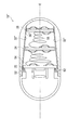
図1は、第1の実施形態であるカプセル型内視鏡の概略的な内部構成を示した図である。図2は、図1の一点鎖線II−IIに沿った概略的断面図である。 FIG. 1 is a diagram illustrating a schematic internal configuration of a capsule endoscope according to the first embodiment. 2 is a schematic cross-sectional view taken along one-dot chain line II-II in FIG.
カプセル型内視鏡10は、外殻となるカプセル状容器12を備え、その一部は半球状(ドーム状)の透明な撮影窓14から成る。樹脂製の容器12の内部には、光源(図示せず)、レンズ54、撮像素子16、そして板状リジッド基板である回路基板22、24、26が収納されている。容器12は、容器12の内部空間12Sを密閉し、撮影窓14は容器12に固着している。
The
レンズ15は、容器12の長手方向(軸方向)Eを光軸として配置され、レンズ15の後方に撮像素子16が設けられている(以下では、撮影窓14側を前方、その逆を後方と定める)。レンズ15は、回路基板22から前方方向に延びるレンズ保持枠18によって固定され、撮像素子16は、回路基板22に設置されている。
The
カプセル型内視鏡10が嚥下によって消化器官内を進行すると、光源(図示せず)から放射される照明光が、撮影窓14を通して前方方向を照らす。観察対象となる器官内壁からの反射光が撮影窓14を介してレンズ15に入射し、これにより被写体像が撮像素子16に形成される。撮像素子16で発生した画像信号は回路基板22において処理され、映像信号が生成される。
When the
映像信号は、回路基板24に設けられた送信部(図示せず)から無線通信によって体外へ送信される。体外に設置されたレシーバが送信された映像信号を受信し、映像信号を再生することにより、体内映像が表示される。回路基板26に設けられた電源制御部(図示せず)は、光源、撮像素子16等への電源供給を制御する。
The video signal is transmitted outside the body by wireless communication from a transmission unit (not shown) provided on the
カプセル型内視鏡の内部構成について説明すると、回路基板22、24、26は、軸Eの後方に向けてこの順番で配置され、基板表面が軸Eの方向を向くように互いに略平行に並んでいる。容器12の内面12Lは、段差をもつようにその断面形状が階段状に形成され、後方に向かうに従って容器12の内部空間12Sが狭くなっていく。ここでは、内面12Lは、径のそれぞれ異なる内面32,34、36に分けられ、回路基板22、24、26は、段差部分となる係止部32K、34K、36Kと接触するように嵌挿されている。
The internal configuration of the capsule endoscope will be described. The
回路基板22、24、26は、内部空間12の筒状構造に合わせてディスク状に形成されている。そして、各回路基板には、電子部品が搭載され、リード線が電子部品と、導体パターン間で延びている。図2には、回路基板24が図示されており、回路基板24には電子部品42、44が搭載され、それぞれリード線41、45が電子部品42、44から延びている。リード線41、45は回路基板に半田付けされ、回路基板42に形成された銅箔の導体パターン43と繋がっている。導体パターン43は、基板周囲に向けて放射状に延びている。
The
容器12の内面12Lには、複数のメタル配線35が軸Eの方向に沿って延びており、係止部32、34、36の断面形状に合わせて配設されている。図2から明らかなように、配線35は、導体パターン43の位置に合わせて配設され、導体パターン43は配線35と接触する。配線35は、導体パターン43各線より太い。回路基板の配線パターンは一般的に銅箔であり、防錆その他の目的で、回路基板にはレジスト(絶縁体)が塗布されるが、配線パターンを露出させる必要がある部分については、金メッキが施されるのが一般的である。本発明においても、導体パターン43のうち、配線35と接触させる部分には金メッキが施され、その他の部分にはレジストが塗布されている。
On the
樹脂製であって絶縁体のコイル状スプリング52、54、56は、回路基板22、24、26と交互に並ぶように設置されている。回路基板22と回路基板24との間には1本のスプリング54が配置され、回路基板22と回路基板24に対して力が作用するように接続している。ただし、電子部品、リード線、導体パターンの障害にならないようにここでは接している。回路基板24と回路基板26との間にも、1本のスプリング56が同様に配置される。一方、回路基板22と撮影窓14の端部14Kとの間には、複数のスプリング52が所定間隔で配置されている。
The coil springs 52, 54, 56 made of resin and insulators are arranged so as to be alternately arranged with the
スプリング52、54、56は、圧縮された状態でそれぞれ接する回路基板を付勢し、スプリング52、54、56全体は、回路基板52、54、56を後方に向けて付勢する。複数のスプリング52の弾性力全体はスプリング54の弾性力よりも強いため、回路基板22は後方へ向けて押される。その結果、回路基板22の周辺部は段差部32Kに当接する。すなわち、後方に向けて回路基板22が係止部32Kに押し付けられる。一方、スプリング54の弾性力はスプリング56の弾性力より大きいため、回路基板24は係止部34Kに押し付けられ、回路基板26は係止部36Kに押し付けられる。
The
回路基板22と回路基板24の距離間隔は、回路基板24と回路基板26の距離間隔より短い。スプリング34、36の弾性係数は等しいことから、スプリン54の弾性力はスプリング56の弾性力より大きくなる。ここでは、回路基板22、24、26の距離間隔にバラツキをもたせることによって、弾性力の大きさを不均一にしている。
The distance between the
カプセル型内視鏡10の組立方法について説明すると、まず、撮影窓14が取り付けられていない容器12の内面に配線35を配設する。ここでは、容器12を回転させながらインクジェットプリンタで導電性インクを吹き付ける。そして、配線35の位置に合わせて回路基板26を内部へ挿入し、順に、スプリング56、回路基板24、スプリング54、回路基板32、スプリング52を容器12の内部へ挿入していく。これらを挿入した後、撮影窓14を装着固定する。なお、配線35は、蒸着などそれ以外の方法で配設してもよい。
The assembly method of the
図2に示すように、回路基板24には切欠部分24Rおよび24Lがそれぞれ形成され、容器12の内面12Lには、切欠部分24Rおよび24Lの形状に合わせて凸部12R、12Lが軸Eに沿ってそれぞれ形成されている。カプセル型内視鏡10の組立時には、この切欠部分24R、24Lの位置に合わせて回路基板の表裏、すなわち挿入方向および装着角度が定められる。容器内面の断面形状は、挿入される回路基板のサイズに応じてあらかじめ定められており、回路基板を入れ替えて異なる回路構成を構築する場合、その基板に合わせて容器が作り替えられる。
As shown in FIG. 2, the
このように第1の実施形態によれば、回路基板22、24、26がカプセル型内視鏡10の容器12の内部に立体的に配置され、回路基板22、24、26の間にスプリング52、54、56が設けられる。そして、スプリング52、54、56の軸Eに沿った弾性力によって、回路基板22、24、26が後方に付勢され、係止部32K、34K、36Kにおいてそれぞれ接触固定される。容器12の内面12Lには、配線35が軸Eに沿って配設され、各回路基板の導体パターンと接触する。これにより、回路基板22、24、26が電気的に互いに接続される。
As described above, according to the first embodiment, the
回路基板とスプリングを交互に容器内部に挿入するだけで回路配置が組み立てられ、接着剤を使うことなく、スプリングの弾性力だけで回路基板を互いに導通させることができ、かつ回路基板を確実に固定することができる。すなわち、回路基板の導通性、装着性の優れたカプセル型内視鏡を効率よく製造することができる。また、回路基板が容器内部に取り付け固定されていないため、回路基板の一部を変更することによって異なる仕様の製品を作ることができる。 By simply inserting the circuit board and the spring into the container, the circuit layout can be assembled. The circuit boards can be connected to each other by the elastic force of the spring without using an adhesive, and the circuit board is securely fixed. can do. That is, it is possible to efficiently manufacture a capsule endoscope with excellent circuit board conductivity and wearability. In addition, since the circuit board is not attached and fixed inside the container, products with different specifications can be made by changing a part of the circuit board.
容器の内面に段差を設け、回路基板の大きさを異なるサイズにしているため、回路基板の装着順を誤る恐れがない。また、回路基板に切欠を設けているため、挿入方向や表裏を特定でき、回路基板を回転させることなく導体パターンを確実に配線と接触させることができる。特に、異なる大きさの切欠を形成しているため、確実に回路基板の取り付け角度が判断できる。さらに、導体パターンの配線に比べて配線35がより太いため、切欠を形成したことによって生じる回路基板に遊び(ガタ)が生じても、一定の接触抵抗が保たれる。
Since the step is provided on the inner surface of the container and the size of the circuit board is made different, there is no possibility that the mounting order of the circuit boards is wrong. Further, since the circuit board is provided with the notches, the insertion direction and the front and back sides can be specified, and the conductor pattern can be reliably brought into contact with the wiring without rotating the circuit board. In particular, since the cutouts having different sizes are formed, the mounting angle of the circuit board can be reliably determined. Further, since the
なお、回路基板の距離間隔を不均一にする代わりに、異なる弾性係数のスプリングを配置してもよい。また、コイルスプリングの代わりに板状スプリング、あるいはスポンジなどの弾性部材を使用してもよい。また、導体パターンを配線より太く設定してもよい。 Instead of making the distance between the circuit boards non-uniform, springs having different elastic coefficients may be arranged. Further, an elastic member such as a plate spring or sponge may be used instead of the coil spring. Further, the conductor pattern may be set thicker than the wiring.
配線の配設については、軸Eに沿って直線的に延ばす代わりに、遅延線としてジグザグ型の配線を設けてもよく、あるいは、回路基板を迂回させる配線、渦巻きパターンの配線に形成してもよい。また、抵抗などの実装品を途中に設けてもよい。さらには、各回路基板の周方向に沿って配線してもよく、あるいは途中の基板の導体パターンとは接触せず、その隣の回路基板の導体パターンと接触するように配線をのばしてもよい。 With regard to the wiring arrangement, instead of extending linearly along the axis E, a zigzag type wiring may be provided as a delay line, or a wiring that bypasses the circuit board or a wiring with a spiral pattern may be formed. Good. Moreover, you may provide mounting goods, such as resistance, in the middle. Furthermore, the wiring may be provided along the circumferential direction of each circuit board, or the wiring may be extended so as not to contact the conductor pattern of the intermediate board and to contact the conductor pattern of the adjacent circuit board. .
回路基板の数、スプリングの数は任意に設定可能であり、スプリング、回路基板を交互に配置すればよい。また、両端にある回路基板に対してはスプリングを介さずに接触固定させてもよい。回路基板を前方方向に付勢させてもよく、また、各回路基板の付勢方向が異なるようにしてもよい。回路基板の形状はディスク形状に限定されず、カプセル容器の内壁形状に合わせて構成されればよい。 The number of circuit boards and the number of springs can be arbitrarily set, and the springs and circuit boards may be arranged alternately. Further, the circuit boards at both ends may be contact-fixed without using a spring. The circuit boards may be urged forward, and the urging directions of the circuit boards may be different. The shape of the circuit board is not limited to the disk shape, and may be configured according to the shape of the inner wall of the capsule container.
次に、図3、4を用いて、第2の実施形態であるカプセル型内視鏡について説明する。第2の実施形態では、回路基板の取り付け角度を変化させることができる。それ以外は、実質的に第1の実施形態と同じである。 Next, a capsule endoscope according to the second embodiment will be described with reference to FIGS. In the second embodiment, the mounting angle of the circuit board can be changed. The rest is substantially the same as the first embodiment.
図3は、第2の実施形態におけるカプセル型内視鏡の概略的断面図である。図4は、回路基板の異なる取り付け角度を示した模式図である。 FIG. 3 is a schematic cross-sectional view of a capsule endoscope according to the second embodiment. FIG. 4 is a schematic view showing different mounting angles of the circuit board.
図3に示すように、回路基板24’には複数の切欠部分が形成されており、一式の切欠62A、62Bと一式の切欠62C、62Dが形成されている。切欠62A、62Bは切欠62C,62Dよりも小さい。容器12’の内面には、2つの凸部24’L、24’Rが所定の間隔をもって形成されている。
As shown in FIG. 3, the circuit board 24 'has a plurality of notches, and a set of
切欠部62A、62Bは凸部24’Lの位置に合わせて形成されており、また、切欠部62C、62Dは、凸部24’Rの位置に合わせて形成されており、回路基板24’の取り付け角度を変えることにより、切欠部62A、62Bのいずれかが凸部24’R切欠部62C〜62Dのいずれか一方が凸部24’Rに嵌合する。
The
図4には、切欠部を省略した回路基板24’が模式的に図示されており、導体パターン43’A、43’Bが交互に並ぶように回路基板24’に積層されている。切欠部62A、切欠部62Cが凸部24’L、凸部24’Rとそれぞれ嵌合するように回路基板24’を取り付けると、導体パターン43’Aが容器12’の内面に配設されたメタル状配線35’と接する。
FIG. 4 schematically shows a
一方、切欠部62B、切欠部62dDが凸部24’Lおよび、凸部24’Rと勘合するように回路基板24’を取り付けると、導体パターン43’Bがメタル状配線35’と接する。なお、図3では、配線35’を図示しておらず、図4では、電子部品、リード線を図示していない。
On the other hand, when the
このように、第2の実施形態によれば、回路基板が異なる角度で取り付けることが可能となる。したがって、同一の回路基板を用いても、取り付け角度を変えることによって電子部品の接続関係を変更し、仕様の異なる製品を作り出すことができる。なお、切欠を設けずに回路基板を回転自在にしてもよく、また、動作中に基板を回転させて動作を切り替えてもよい。 Thus, according to the second embodiment, the circuit boards can be attached at different angles. Therefore, even if the same circuit board is used, the connection relationship of electronic components can be changed by changing the mounting angle, and products with different specifications can be created. Note that the circuit board may be rotatable without providing a notch, or the operation may be switched by rotating the board during operation.
次に、図5を用いて、第3の実施形態であるカプセル型内視鏡について説明する。第3の実施形態では、容器内面が傾斜面として構成される。それ以外の構成は、実質的に第1の実施形態と同じである。 Next, a capsule endoscope according to a third embodiment will be described with reference to FIG. In the third embodiment, the inner surface of the container is configured as an inclined surface. Other configurations are substantially the same as those in the first embodiment.
図5は、第3の実施形態であるカプセル型内視鏡の概略的な内部構成を示した図である。図5に示すように、カプセル型内視鏡10”の内面32”は、軸Eに沿ってテーパー状に形成され、配線35”が軸Eに沿って内面32”に配設されている。回路基板22、24、26は、それぞれスプリング52、54、56によって後方へ付勢され、各基板の周縁部が内面32”と係止する。これにより、回路基板22、24、26が配線35”によって互いに導通する。内面12”Lのテーパー形状は、回路基板22、24、26のサイズに合わせて定められる。
FIG. 5 is a diagram illustrating a schematic internal configuration of a capsule endoscope according to the third embodiment. As shown in FIG. 5, the
このように容器内面をテーパー状に形成することにより、回路基板の配置する数を任意に変更することが可能であり、新たな回路基板を加える場合、容器を作り直すことなく、回路基板、スプリングの順番で交互に容器内部へ挿入することができる。 By forming the inner surface of the container in a tapered shape in this way, it is possible to arbitrarily change the number of circuit boards to be arranged. When a new circuit board is added, the circuit board and the spring are not remade. It can be inserted into the container alternately in order.
次に、図6、7を用いて、第4の実施形態であるカプセル型内視鏡について説明する。第4の実施形態では、回路基板の周囲から中心方向に向けて付勢する。それ以外の構成については、実質的に第1の実施形態と同じである。 Next, a capsule endoscope according to a fourth embodiment will be described with reference to FIGS. In the fourth embodiment, the bias is applied from the periphery of the circuit board toward the center. Other configurations are substantially the same as those in the first embodiment.
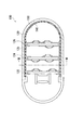
図6は、第4の実施形態であるカプセル型内視鏡の概略的な内部構成を示した図である。図7は、図6のラインVII−VIIに沿った概略的断面図である。 FIG. 6 is a diagram illustrating a schematic internal configuration of a capsule endoscope according to the fourth embodiment. FIG. 7 is a schematic cross-sectional view taken along line VII-VII in FIG.
カプセル型内視鏡100は、容器120の内面に空気などの気体、あるいは液体を封入する空間部130が形成され、ゴムなどの弾性部材140が空間部130を覆うように容器120の内面に貼り付けられている。配線135は、弾性部材140の表面に配設され、回路基板122、124、126は、配線135の位置に合わせて容器120の内部に嵌挿される。ただし、回路基板122、124、126のサイズはどれも等しい。
In the
図7に示すように、空間部130は圧縮気体あるいは液体によって十分満たされ、弾性部材140は回路基板124を覆い、空間部130から力を受けて回路基板124を基板中心方向へ向けて付勢する。これにより、回路基板124が固定される。その他の回路基板122、126も同じように固定される。ただし、図7では、電子部品、リード線、導体パターンを図示していない。
As shown in FIG. 7, the
このように、弾性部材140が回路基板の周囲から中心に向けて力を与えることにより、弾性部材140の位置が固定され、配線と良好に接触導通する。
As described above, the
なお、スプリングは不導体としたが、導体のスプリングによって回路基板を互いに導通させてもよい。また、回路基板を接触固定させるため、スプリングを含めた弾性部材以外の部材によって回路基板を付勢するように構成してもよい。さらに、カプセル型内視鏡以外の嚥下用医療機器などカプセル型医療機器に対して同様の回路基板の配置構成を適用してもよい。 Although the spring is non-conductive, the circuit boards may be electrically connected to each other by a conductive spring. Further, in order to contact and fix the circuit board, the circuit board may be urged by a member other than an elastic member including a spring. Furthermore, a similar circuit board arrangement may be applied to capsule medical devices such as swallowing medical devices other than capsule endoscopes.
10 カプセル型内視鏡
12 容器
12L 内面
12S 内部空間
16 撮像素子
22、24、26 回路基板
32K、34K、36K 係止部
35 配線(導電体)
43 導体パターン
52、54、56 スプリング(付勢部材)
DESCRIPTION OF
43
Claims (13)
前記容器の軸方向に並べられる複数の回路基板と、
前記容器の内面に沿って配設され、前記複数の回路基板を互いに導通させる導電体と、
前記複数の回路基板を付勢する付勢部材とを備え、
各回路基板が、前記導電体と接触し、前記付勢部材による力によって前記容器の内面に接触固定されることを特徴とするカプセル型内視鏡。 A capsule container;
A plurality of circuit boards arranged in the axial direction of the container;
A conductor disposed along an inner surface of the container and electrically connecting the plurality of circuit boards;
A biasing member that biases the plurality of circuit boards,
Each of the circuit boards comes into contact with the conductor and is fixed to the inner surface of the container by the force of the urging member.
容器内に設けられる複数の回路基板と、
前記複数の回路基板と接触し、前記複数の回路基板を互いに導通させる導電体と、
前記複数の回路基板それぞれを前記容器の内面に接触固定させる付勢部材と
を備えたことを特徴とするカプセル型医療機器。 A capsule container;
A plurality of circuit boards provided in the container;
A conductor in contact with the plurality of circuit boards and electrically connecting the plurality of circuit boards to each other;
A capsule-type medical device comprising: an urging member that contacts and fixes each of the plurality of circuit boards to the inner surface of the container.
Priority Applications (1)
| Application Number | Priority Date | Filing Date | Title |
|---|---|---|---|
| JP2007184032A JP2009018077A (en) | 2007-07-13 | 2007-07-13 | Capsule endoscope and medical capsule device |
Applications Claiming Priority (1)
| Application Number | Priority Date | Filing Date | Title |
|---|---|---|---|
| JP2007184032A JP2009018077A (en) | 2007-07-13 | 2007-07-13 | Capsule endoscope and medical capsule device |
Publications (1)
| Publication Number | Publication Date |
|---|---|
| JP2009018077A true JP2009018077A (en) | 2009-01-29 |
Family
ID=40358226
Family Applications (1)
| Application Number | Title | Priority Date | Filing Date |
|---|---|---|---|
| JP2007184032A Pending JP2009018077A (en) | 2007-07-13 | 2007-07-13 | Capsule endoscope and medical capsule device |
Country Status (1)
| Country | Link |
|---|---|
| JP (1) | JP2009018077A (en) |
Cited By (3)
| Publication number | Priority date | Publication date | Assignee | Title |
|---|---|---|---|---|
| JP2010069209A (en) * | 2008-09-22 | 2010-04-02 | Olympus Medical Systems Corp | Capsule medical apparatus and method of manufacturing capsule medical apparatus |
| WO2012073634A1 (en) * | 2010-11-29 | 2012-06-07 | オリンパスメディカルシステムズ株式会社 | Capsule medical device and method for manufacturing same |
| CN110604535A (en) * | 2019-09-23 | 2019-12-24 | 安翰科技(武汉)股份有限公司 | Capsule core and capsule endoscope |
-
2007
- 2007-07-13 JP JP2007184032A patent/JP2009018077A/en active Pending
Cited By (4)
| Publication number | Priority date | Publication date | Assignee | Title |
|---|---|---|---|---|
| JP2010069209A (en) * | 2008-09-22 | 2010-04-02 | Olympus Medical Systems Corp | Capsule medical apparatus and method of manufacturing capsule medical apparatus |
| US8460174B2 (en) | 2008-09-22 | 2013-06-11 | Olympus Medical Systems Corp. | Capsule medical apparatus with board-separation keeping units |
| WO2012073634A1 (en) * | 2010-11-29 | 2012-06-07 | オリンパスメディカルシステムズ株式会社 | Capsule medical device and method for manufacturing same |
| CN110604535A (en) * | 2019-09-23 | 2019-12-24 | 安翰科技(武汉)股份有限公司 | Capsule core and capsule endoscope |
Similar Documents
| Publication | Publication Date | Title |
|---|---|---|
| JP4366356B2 (en) | Image pickup module and image pickup module assembling method | |
| US20150228678A1 (en) | Image pickup apparatus, endoscope, semiconductor apparatus, and manufacturing method of semiconductor apparatus | |
| JP5806343B2 (en) | Photoelectric composite module, camera head, and endoscope apparatus | |
| CN106886089B (en) | Endoscope with a detachable handle | |
| JP5155700B2 (en) | connector | |
| WO2002102224A2 (en) | In vivo sensing device with a circuit board having rigid sections and flexible sections | |
| JP2009201762A (en) | Endoscope and photographing module | |
| CN105101864A (en) | Endoscope device | |
| JP2013206617A (en) | Cable connection structure, ultrasonic probe, and ultrasonic endoscope system | |
| EP2116177B1 (en) | Capsule type medical device | |
| JP4700756B2 (en) | Capsule endoscope | |
| WO2019044609A1 (en) | Endoscope | |
| JP2009018077A (en) | Capsule endoscope and medical capsule device | |
| JP2011045173A (en) | Cable assembly, electronic circuit module, and image pickup device | |
| US20100053391A1 (en) | Miniaturized image capturing device and method for assembling the same | |
| US20060015013A1 (en) | Device and method for in vivo illumination | |
| JPS63313970A (en) | Solid-state image pickup device | |
| KR200446281Y1 (en) | Capsule endoscope having flexible electric circuit board thereof | |
| US10757309B2 (en) | Endoscope imaging module with signal cable and flexible linear structure | |
| CN106794002A (en) | Ultrasonic probe | |
| JP2009018078A (en) | Capsule endoscope and medical capsule device | |
| JP4562998B2 (en) | Capsule endoscope | |
| JP6457057B2 (en) | connector | |
| JP6132963B2 (en) | Cable connection structure, ultrasound probe and ultrasound endoscope system | |
| JP7370559B2 (en) | Circuit boards, board modules, and device modules |