JP2009003918A - System for automatically creating software interface - Google Patents
System for automatically creating software interface Download PDFInfo
- Publication number
- JP2009003918A JP2009003918A JP2008100016A JP2008100016A JP2009003918A JP 2009003918 A JP2009003918 A JP 2009003918A JP 2008100016 A JP2008100016 A JP 2008100016A JP 2008100016 A JP2008100016 A JP 2008100016A JP 2009003918 A JP2009003918 A JP 2009003918A
- Authority
- JP
- Japan
- Prior art keywords
- module
- interface
- platform
- software
- functional
- Prior art date
- Legal status (The legal status is an assumption and is not a legal conclusion. Google has not performed a legal analysis and makes no representation as to the accuracy of the status listed.)
- Pending
Links
- 238000013461 design Methods 0.000 claims abstract description 34
- 238000004088 simulation Methods 0.000 claims abstract description 17
- 230000000007 visual effect Effects 0.000 claims abstract description 17
- 238000013519 translation Methods 0.000 claims abstract description 10
- 238000012360 testing method Methods 0.000 claims abstract description 7
- 238000012795 verification Methods 0.000 claims description 15
- 230000007704 transition Effects 0.000 claims description 4
- 238000010200 validation analysis Methods 0.000 abstract 2
- 238000004904 shortening Methods 0.000 abstract 1
- 230000006870 function Effects 0.000 description 7
- 230000014616 translation Effects 0.000 description 7
- 238000000034 method Methods 0.000 description 6
- 238000010586 diagram Methods 0.000 description 5
- 230000008569 process Effects 0.000 description 5
- 238000004891 communication Methods 0.000 description 4
- 239000004973 liquid crystal related substance Substances 0.000 description 3
- 230000009471 action Effects 0.000 description 2
- 230000008859 change Effects 0.000 description 2
- 230000003213 activating effect Effects 0.000 description 1
- 239000003086 colorant Substances 0.000 description 1
- 230000007547 defect Effects 0.000 description 1
- 230000003111 delayed effect Effects 0.000 description 1
- 238000001514 detection method Methods 0.000 description 1
- 230000000977 initiatory effect Effects 0.000 description 1
- 239000000463 material Substances 0.000 description 1
- 238000012986 modification Methods 0.000 description 1
- 230000004048 modification Effects 0.000 description 1
- 239000011295 pitch Substances 0.000 description 1
- 238000012545 processing Methods 0.000 description 1
- 239000010409 thin film Substances 0.000 description 1
- 230000001960 triggered effect Effects 0.000 description 1
Images


Classifications
-
- G—PHYSICS
- G06—COMPUTING; CALCULATING OR COUNTING
- G06F—ELECTRIC DIGITAL DATA PROCESSING
- G06F8/00—Arrangements for software engineering
- G06F8/30—Creation or generation of source code
- G06F8/38—Creation or generation of source code for implementing user interfaces
Abstract
Description
本発明は、車両における人と電子装置との間の通信の分野に関する。 The present invention relates to the field of communication between a person and an electronic device in a vehicle.
従来では、CDプレーヤーなどの電子装置と通信するために、ユーザはCDの再生や曲の変更を開始する目的でボタン、ローレットホイール、カーソルなどのプレーヤーの制御要素を操作する。
ところが運搬車両、より具体的に言うと自動車の電子装置の数が増えたことによって、ダッシュボード上の制御要素の数を制限する必要が出てきた。実際にはダッシュボードの表面は制限されているので、その上にこういった装置それぞれの制御要素を配置するのは不可能である。
Conventionally, in order to communicate with an electronic device such as a CD player, the user operates player control elements such as buttons, knurling wheels, cursors, etc., for the purpose of initiating CD playback and song changes.
However, with the increase in the number of transport vehicles, more specifically automobile electronics, it has become necessary to limit the number of control elements on the dashboard. In practice, the dashboard surface is limited, so it is not possible to place the control elements of each of these devices on it.
限られた数の制御要素で多数の電子装置と通信するためには、要素とプラットフォームに配置される装置の機能コアとのソフトウェアインタフェースを実現する必要がある。分かりやすくするため、そしてコアの意味を説明するために、CDプレーヤーの機能コアは、例えば、再生レンズ、レーザヘッド、CDを回転させるための手段を含む。ソフトウェアインタフェースを通じて、幾つかの機能コアを制御するために制御要素を使用できる。 In order to communicate with a large number of electronic devices with a limited number of control elements, it is necessary to implement a software interface between the elements and the functional cores of the devices located on the platform. For clarity and to explain the meaning of the core, the functional core of the CD player includes, for example, a playback lens, a laser head, and means for rotating the CD. Control elements can be used to control several functional cores through a software interface.
ソフトウェアインタフェースの実現は、多数のステップを伴う長く要求の厳しいプロセスである。 Implementing a software interface is a long and demanding process with many steps.
従来では、こういったプロセスは、トレーシングペーパー上に種々の色の付いた形を使用して装置の機能コアの制御に必要な制御要素を図式化するステップを伴う理論上の「プロトタイピング」ステップを含む。例えば、ラジオ受信機を含む自動車ラジオの場合、表示領域を表す矩形とボタンを表す色の付いた円盤がトレーシングペーパー上に定義される。 Traditionally, this process is a theoretical "prototyping" that involves the steps of using various colored shapes on tracing paper to diagram the control elements necessary to control the functional core of the device. Includes steps. For example, in the case of a car radio including a radio receiver, a rectangle representing a display area and a colored disk representing a button are defined on the tracing paper.
プロトタイピングステップは、制御要素と装置の機能コアとの関係を定義できるようにした仕様の作成を含むステップを伴う。したがって前の例に戻って言うと、この仕様では、ボタンを作動させるとラジオ受信機が作動して捕獲した局の名前や歌のタイトルを表示領域に送信するということが規定されている。こういった仕様によって、ソフトウェアインタフェースの要求を定義することができる。 The prototyping step involves creating a specification that allows the relationship between the control elements and the functional core of the device to be defined. Therefore, returning to the previous example, this specification stipulates that when the button is activated, the radio receiver is activated and the captured station name and song title are transmitted to the display area. These specifications can define software interface requirements.
コーディングステップでは、仕様を種々の装置の機能コアが解釈できる言語に翻訳する。 In the coding step, the specification is translated into a language that can be interpreted by the functional cores of the various devices.
一般的に言うと、電子装置は実行の速度やエラーのチェックを向上させるいわゆる「低レベル」言語は解釈することができ、こういったコーディングタイプはあらゆる車載システムで従来から使用されている。こういった言語は、グラフィックスを強化するプロトタイプの実現のために使用するいわゆる「高レベル」言語とは対照的である。 Generally speaking, electronic devices can interpret so-called “low-level” languages that improve execution speed and error checking, and these coding types are traditionally used in all in-vehicle systems. These languages are in contrast to so-called “high-level” languages that are used to implement graphics-enhancing prototypes.
コーディングステップは仕様書に基づいており、機能コアそれぞれについて個別的に実施される。その理由は、ここでも先の例で説明すると、ヘルツラジオ受信機を有する自動車ラジオと衛星ラジオ受信機を有する自動車ラジオについて個別のコーディングを実行する必要があるためである。生成したコードを車両に配置されている管理モジュールに送信する。この管理モジュールは、制御要素と機能コアとの通信を自律的に管理する。 The coding steps are based on specifications and are performed individually for each functional core. This is because, again in the previous example, it is necessary to perform separate coding for the car radio with the Hertz radio receiver and the car radio with the satellite radio receiver. The generated code is transmitted to the management module arranged in the vehicle. The management module autonomously manages communication between the control element and the functional core.
ソフトウェアインタフェースの作成は、制御要素と機能コアとの通信をこの要素を操作するユーザがテストする実際のシミュレーションステップで完了する。 The creation of the software interface is completed in the actual simulation step where the user operating the element tests the communication between the control element and the functional core.
インタフェースを作成するこういった従来のプロセスには、多数の欠点がある。 These conventional processes for creating interfaces have a number of drawbacks.
コーディングステップの際、技術上の理由から仕様書が厳密に順守されず、その結果機能または表示モードをコーディングできない事態が起こり得る。 During the coding step, it may happen that the technical specifications are not strictly adhered to for technical reasons, and as a result the function or display mode cannot be coded.
さらに、仕様を作成した時に既に承認したトレーシングペーパーのグラフィックスがもはや不適当であるといった事態もよくあることである。そうなるとプロトタイプを再度定義し、仕様を修正し、ソフトウェアインタフェースを再度コーディングしなければならない。それまでの設計ステップを繰り返すことによって、設計サイクルが延長してしまう。 Furthermore, it is often the case that the tracing paper graphics that were already approved when the specification was created are no longer appropriate. Then the prototype must be redefined, the specification modified, and the software interface recoded. Repeating the previous design steps will extend the design cycle.
またさらに、機能コアの物質的な修正がインタフェースの設計中に生じる可能性もある。そのため、仕様を認証したにも関わらず幾つかの機能が削除または追加されるため、ソフトウェアインタフェースの作成を再度始めなければならない。 Still further, material modification of the functional core may occur during interface design. For this reason, some functions are deleted or added even though the specification is certified, and the creation of the software interface must be started again.
ソフトウェアインタフェース、いわゆるヒューマン・マシーンインタフェース(HMI)の作成は、緻密で時間のかかるプロセスである。柔軟性に欠けるために、制御要素と機能コアとの通信がうまくいくという保証も一切ないまま設計ステップを繰り返さなければならない。 The creation of a software interface, the so-called human machine interface (HMI), is an elaborate and time consuming process. Due to the lack of flexibility, the design steps must be repeated without any guarantee that the communication between the control element and the functional core will be successful.
本願の発明は、こういった欠点の克服を目的とする。そのために、本発明は、オペレータと、ターゲットプラットフォームに配置された電子装置の機能コアと、の間のソフトウェアインタフェースの自動作成システムに関し、このシステムは、
プラットフォームの制御要素に対応する複数のインタフェース視覚要素が配置された設計ウィンドウと、複数のインタフェース視覚要素が機能的に接続されている状態機械と、を含む設計モジュールと、
この設計モジュールから発せられたデータが、前記機能コアの特性とマッチするかどうかをテストする検証モジュールと、
検証モジュールから発せられたデータを変換しプラットフォームの管理要素に送信する翻訳ユニットを備えており、前記制御要素によって前記機能コアをシミュレートするためのターゲットプラットフォームのシミュレーションモジュールと、を備える。
The present invention aims to overcome these drawbacks. To that end, the present invention relates to a system for automatically creating a software interface between an operator and a functional core of an electronic device located on a target platform, the system comprising:
A design module including a design window in which a plurality of interface visual elements corresponding to platform control elements are disposed; and a state machine in which the plurality of interface visual elements are functionally connected;
A verification module that tests whether data generated from this design module matches the characteristics of the functional core;
A translation unit that converts data sent from the verification module and sends it to a management element of the platform, and a simulation module of the target platform for simulating the functional core by the control element.
本発明のシステムによって、有利には、インタフェースの作成サイクルを短くできると同時に、設計上の柔軟性を与えることができる。本発明の作成システムは多目的型で、あらゆる種類の装置に適応できる。 The system of the present invention can advantageously shorten design cycles of the interface while providing design flexibility. The production system of the present invention is multi-purpose and can be applied to all kinds of devices.
好ましくは、本発明のシステムは、検証モジュールからのデータを、電子装置の機能コアと接続せずにシミュレートするように構成されたソフトウェアデバイスプラットフォームのシミュレーションモジュールを備えている。 Preferably, the system of the present invention comprises a software device platform simulation module configured to simulate data from the verification module without connection to the functional core of the electronic device.
したがって、物理的な装置に依存せずに本発明のインタフェースをテストできるため、こういった装置が利用不可能な場合にインタフェース作成が遅くなってしまう事態を回避できる。 Therefore, since the interface of the present invention can be tested without depending on a physical device, it is possible to avoid a situation in which interface creation is delayed when such a device cannot be used.
さらに好ましくは、本発明のインタフェースは、ソフトウェアデバイスプラットフォームのシミュレーションモジュールに接続されたコンピュータによってシミュレートされる。 More preferably, the interface of the present invention is simulated by a computer connected to the simulation module of the software device platform.
さらに好ましくは、電子装置の機能コアからのデータは、コンピュータモニタに表示される。 More preferably, data from the functional core of the electronic device is displayed on a computer monitor.
好ましくは、インタフェース視覚要素は、電子装置の機能コアの特性に対応する属性を備えている。 Preferably, the interface visual element comprises attributes corresponding to characteristics of the functional core of the electronic device.
こういったことによって、視覚要素と機能コアとの不適合を一切懸念することなく、アプリケーションをターゲットプラットフォームで有利に実施できる。 This allows the application to be advantageously implemented on the target platform without any concern about incompatibilities between visual elements and functional cores.
さらに好ましくは、状態機械はインタフェースの種々の起こり得る状態を表す複数のブロックを含み、こういったブロックが種々の状態間の遷移手段を表すリンクによって接続されている。 More preferably, the state machine includes a plurality of blocks representing various possible states of the interface, these blocks being connected by links representing transition means between the various states.
さらに好ましくは、ターゲットシミュレーションモジュールの翻訳ユニットは、電子装置の機能コアに応じてパラメータ化されている。 More preferably, the translation unit of the target simulation module is parameterized according to the functional core of the electronic device.
本発明は、以下の説明と添付図面によってよりよく理解されるであろう。 The invention will be better understood from the following description and the accompanying drawings.
自動車は、レジャー用の電子装置(CD/DVDプレーヤー、ラジオ受信機)、あるいは、運転に直接関係する目的のために使用する電子装置(GPS受信機、レーダー探知機)を数台搭載している。ラジオ受信機のみを搭載した自動車の場合、当該ラジオ受信機の制御要素が、このラジオ受信機を制御するために用いられ、制御要素としては、可動カーソルやプッシュボタンまたは回転ボタンが含まれる。 Cars are equipped with several electronic devices for leisure (CD / DVD players, radio receivers) or electronic devices (GPS receivers, radar detectors) used for purposes directly related to driving. . In the case of an automobile equipped with only a radio receiver, a control element of the radio receiver is used to control the radio receiver, and the control element includes a movable cursor, a push button, or a rotation button.
車両がこういった装置の幾つかを搭載している場合、自動車のダッシュボードの上に全ての装置の制御要素を配置するのは不可能である。 If the vehicle is equipped with some of these devices, it is not possible to place the control elements of all devices on the dashboard of the car.
そこで、制御要素を有する種々の装置を、そういった装置の機能コアを集めたレジャー用プラットフォームに置き換える。CDプレーヤーの機能コアは、例えば、再生レンズ、レーザヘッド、CDを回転させるための手段を含む。限られた数の制御要素で多数の電子装置と通信するためには、こういった要素と装置の機能コアとの間のソフトウェアインタフェースを実施することが必要になる。 Therefore, various devices having control elements are replaced with leisure platforms that collect the functional cores of such devices. The functional core of the CD player includes, for example, a reproducing lens, a laser head, and a means for rotating the CD. In order to communicate with a large number of electronic devices with a limited number of control elements, it is necessary to implement a software interface between these elements and the functional core of the device.
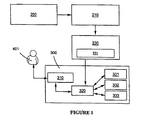
こういったソフトウェアインタフェースの自動作成システムについて説明する前に、ラジオ受信機の機能コア331、CDプレーヤーの機能コア332、GPSユニットの機能コア333を含む、自動車用のマルチメディアレジャープラットフォーム300を一例として参照して種々の構成モジュールについて詳細に言及する。
Before explaining such a software interface automatic creation system, an automobile
このターゲットプラットフォーム300は、プッシュボタン、回転ボタン、そして液晶ディスプレイ画面(LCD)(図示せず)などの制御要素310をさらに含む。プラットフォーム300は、ユーザ401から制御要素310を介して受け取った種々の制御を処理するために、車載計算機などの管理要素320を含む。制御要素は、管理要素320によってコア331、332、333に転送される。
The
インタフェース作成システムは、制御要素310を、機能コア331、332、333と理論上通信させる、以下で説明する設計モジュール200を含む。この設計モジュール200は、当該設計モジュール200に与えられたデータが機能コア331、332、333の特性と一致するかどうかをチェックするように構成された検証モジュール210と接続している。例えば、検証モジュール210によって、画面のサイズがGPSユニット333のビデオ出力に適合する寸法を示しているかどうかをチェックすることができる。
The interface creation system includes a
次いで検証モジュール210から発せられたデータは、ターゲットプラットフォームのシミュレーションモジュール230に転送される。このモジュールは、データを管理要素320が解釈可能な言語に変換する翻訳ユニット231を含む。こうして、プラットフォーム300のソフトウェアインタフェースは、制御要素310によって自律的にシミュレートされる。こういった例示の実施形態では、モジュール200、210、230は、(図示しない)コンピュータなどに集められている。
The data emitted from the
図2を参照すると、設計モジュール200は、設計ウィンドウ1を含む。こういったウィンドウ1には、プッシュボタン21、22、23や回転ボタン24を表す色の付いた円盤、そしてテキスト、写真またはビデオなどの種々のグラフィカル特徴を表示するための液晶画面(LCD)10を表す矩形といったグラフィカルフォームが表示されている。こういったグラフィカルフォームを、インタフェース視覚要素10、21、22、23、24と呼ぶ。
Referring to FIG. 2, the
こういったインタフェース視覚要素10、21、22、23、24は、インタフェースされるユニットのコアの機能特性に対応する機能属性を持っている。例えば、矩形10は、ここでは画面の解像度、表示可能な色の数、更新の頻度を属性として持っている。同様に、回転ボタンの属性は、回転におけるピッチ数と、逆戻りしない力(no-return force)の度合い、である。したがって、LCD(液晶ディスプレイ)型のディスプレイ画面を有する第1のプラットフォームと、TFT(薄膜トランジスタ)型のディスプレイ画面を有する第2のプラットフォーム、の2つの同じ部類のレジャープラットフォームの場合、同じ設計ウィンドウ1を同じインタフェース視覚要素と共に使用でき、その属性のみが異なる。
These interface
図3を参照すると、設計モジュール200は、設計ウィンドウ1に配置されているインタフェース視覚要素10、21、22、23、24の論理的、順次的、かつ機能的行動を定義できるダイアグラム、すなわち状態機械100をさらに含む。この機械100は、種々のインタフェース視覚要素10、21、22、23、24の作動時の状態を表す。
Referring to FIG. 3, the
インタフェース視覚要素21、22、23は、ラジオ受信機のコア331、オーディオCDプレーヤーのコア332、GPSユニットのコア333をそれぞれ作動させ、回転ボタン24は種々の機能コアの切り換えを可能にする。
The interface
状態機械100は、種々のインタフェース状態を表すブロック51、52、53のセットの形式で、ブロック51、52、53は状態間の遷移に対応するリンクによって互いに接続されている。
The
インタフェース作動時の初期状態が状態機械100に示され、これはINIの略語で状態ブロック51に示されている。
The initial state when the interface is activated is shown in
状態ブロック51、52、53は、ここではラジオ受信機のコア331、オーディオCDプレーヤーのコア332、GPSユニットのコア333のアクティブ状態にそれぞれ対応する。
Here, the state blocks 51, 52, and 53 correspond to the active states of the
初期状態では、ラジオが作動される。もしもCDプレーヤーに対応する要素22に何らかの作用を行うと、ラジオの作動は止まり、オーディオCDプレーヤーが作動する。そしてシステムはブロック52で表される状態になる。同様に、ボタン23を作動すると、ブロック53で表される状態に手順が進み、GPSユニットが作動すされる。つまり、ボタン21、22、23によってプラットフォーム300の種々の機能の切り替えを便利に行える。
In the initial state, the radio is activated. If any action is taken on the
同様に、システムの状態がブロック51によって表される場合(ラジオ状態)、ボタン21(ラジオボタン)を作動させても状態は変わらない。 Similarly, if the system status is represented by block 51 (radio status), operating the button 21 (radio button) does not change the status.
プラットフォーム300の異なる機能を切り換えるために、回転ボタン24を使用する。システムの状態がブロック51によって表されている場合、GPS機能(状態53)に切り換えるにはボタン24を左に回転させ、CD機能(状態52)に切り換えるにはボタンを右に回転させればよい。図3の点線は、回転ボタン24を回転させたときの種々の状態間の遷移を表す。
To switch between different functions of the
こういった全ての作用によって、ラジオ局名、アーティスト名、曲名の表示といったディスプレイ画面10や受信している周波数の変更が行われる。
All of these actions change the
インタフェース視覚要素10、21、22、23、24を設計ウィンドウ1に配置する際、同時にこういった要素を状態図100にも配置できるため、要素の全ての属性に迅速にアクセスできる。
When the interface
設計ウィンドウ1と状態図100の両方において、設計モジュール200で追加されたデータは、チェックのために検証モジュール210に送信される。
In both the
検証モジュール210によって、状態機械100で定義したイベントの論理シーケンスと設計ウィンドウ1で定義した視覚要素22、23、24が適当なフォーマットで入力され、ユニットの機能コア331、332、333の特性と一致することを保証できる。
The
こういった自動検証ステップは、インタフェース設計時のどの段階でも行い得る。例えば、各ボタン21、22、23を設計ウィンドウ1に挿入した後にインタフェースを検証することができる。こういった部分的な検証によって、いかなるエラーのリスクを回避することができるため、インタフェースの品質を向上させることができる。つまり、こういったことによってインタフェース作成の全体的なプロセスにかかる時間の節約につながる。
These automatic verification steps can be performed at any stage during interface design. For example, the interface can be verified after each
設計モジュール200からのデータがモジュール210によって検証されると、データはターゲットプラットフォームのシミュレーションモジュール230、いわゆるターゲットシミュレーションモジュールに送信され、制御要素310によってインタフェースをシミュレートする。
When data from the
設計モジュール200で使用するソフトウェア言語は、プラットフォーム300の管理要素320で使用する言語とは異なる。そこで、実際のシミュレーションを実行するために、ターゲットシミュレーションモジュール230の翻訳ユニット231によって、設計データを、プラットフォーム300の管理要素320が解釈可能ないわゆる「ターゲット」低レベル言語に変換することができる。こういった翻訳は自動的に実行されるため、時間の節約になる。
The software language used in the
さらに、翻訳ユニット231は、これが含む機能コア331、332、333の関数としてパラメータ化できる。したがって自動車のレジャープラットフォームの部類では、生成されたコードを同部類の種々のプラットフォームに適用するために、翻訳ユニット231のパラメータ化を修正することで十分である。
Furthermore, the
実際のテストでは、ユーザ401は制御要素310を作動させ、機能コアの行動を観察し、ターゲットプラットフォーム300上での実行において典型的な欠陥を検出する。
In an actual test, the
本発明の別の実施形態では、プラットフォーム300または機能コア331、332、333が利用できないか、または物理的なプラットフォーム300にも制御要素310にも一切依存せずにテストを実行するのが望ましい場合が生じ得る。こういった仮定で図4を参照すると、設計モジュール200からのデータは、ソフトウェアデバイスプラットフォームのシミュレーションモジュール220、いわゆるソフトウェアシミュレーションモジュール220に送信され、そこでモジュール220に接続されたコンピュータ250などによって作成されたインタフェースをシミュレートする。
In another embodiment of the present invention, when
オペレータ401と原則として同一人物のオペレータ402が、ソフトウェアシミュレーションモジュール220を使用してインタフェースをテストし、コンピュータマウスでボタン22をクリックしてオーディオCDプレーヤーを作動させることで、コンピュータ250のモニタに表示される設計ウィンドウ100の矩形10への「CD」というテキストの表示がトリガされる。
The
設計者またはカスタマであるオペレータは、プラットフォーム300に依存しなくてもインタフェースの品質を評価することができる。その理由は、プラットフォーム300のコアがなくてもインタフェースを常に開発することが可能なためである。さらに、こういった「理論上の」インタフェースは検証モジュール210によって検証されているため、プラットフォーム300や利用不可能なコアとインタフェースとの将来の適合性が保証される。
An operator who is a designer or a customer can evaluate the quality of the interface without depending on the
本明細書中で使用されているように、ボタン、ローレットホイール、カーソル、他のハンドルといった用語は、音声(例えば、声)コマンド、ビジュアルコマンド(ユーザの動きの検出)、タッチコマンド(タッチ画面)、そしていわゆる「ワイヤレス」コマンド(赤外線、ブルートゥース、ワイファイ、電波など)といった、装置機能を作動させるための全ての手段も含む。 As used herein, terms such as buttons, knurled wheels, cursors, and other handles refer to voice (eg, voice) commands, visual commands (detection of user movement), touch commands (touch screen). And all means for activating device functions, such as so-called “wireless” commands (infrared, Bluetooth, WiFi, radio, etc.).
Claims (7)
設計モジュール(200)と、検証モジュール(210)と、前記ターゲットプラットフォーム(300)のシミュレーションモジュール(230)と、を備え、
前記設計モジュール(200)は、前記プラットフォーム(300)の制御要素(310)に対応する複数のインタフェース視覚要素(10、21、22、23、24)が配置された設計ウィンドウ(1)と、前記複数のインタフェース視覚要素(10、21、22、23、24)が機能的に接続されている状態機械(100)と、を含み、
前記検証モジュール(210)は、前記設計モジュール(200)から発せられたデータが前記機能コア(331、332、333)の特性とマッチするかどうかをテストし、
前記シミュレーションモジュール(230)は、前記検証モジュールから発せられたデータを変換し前記ターゲットプラットフォーム(300)の管理要素(320)に送信する翻訳ユニット(231)を含み、前記制御要素(310)によって前記機能コア(331、332、333)をシミュレートする、
ソフトウェアインタフェースの自動作成システム。 A system for automatically creating a software interface between an operator (401) and a functional core (331, 332, 333) of an electronic device disposed on a target platform (300),
A design module (200), a verification module (210), and a simulation module (230) of the target platform (300),
The design module (200) includes a design window (1) in which a plurality of interface visual elements (10, 21, 22, 23, 24) corresponding to the control elements (310) of the platform (300) are arranged; A state machine (100) to which a plurality of interface visual elements (10, 21, 22, 23, 24) are operatively connected;
The verification module (210) tests whether the data emitted from the design module (200) matches the characteristics of the functional cores (331, 332, 333);
The simulation module (230) includes a translation unit (231) that converts data transmitted from the verification module and transmits the data to a management element (320) of the target platform (300). Simulate functional cores (331, 332, 333)
Software interface automatic creation system.
Applications Claiming Priority (1)
| Application Number | Priority Date | Filing Date | Title |
|---|---|---|---|
| FR0702615A FR2915016B1 (en) | 2007-04-10 | 2007-04-10 | SYSTEM FOR AUTOMATED CREATION OF A SOFTWARE INTERFACE |
Publications (1)
| Publication Number | Publication Date |
|---|---|
| JP2009003918A true JP2009003918A (en) | 2009-01-08 |
Family
ID=38625897
Family Applications (1)
| Application Number | Title | Priority Date | Filing Date |
|---|---|---|---|
| JP2008100016A Pending JP2009003918A (en) | 2007-04-10 | 2008-04-08 | System for automatically creating software interface |
Country Status (5)
| Country | Link |
|---|---|
| US (1) | US20080255823A1 (en) |
| EP (1) | EP1980941A1 (en) |
| JP (1) | JP2009003918A (en) |
| CN (1) | CN101290508B (en) |
| FR (1) | FR2915016B1 (en) |
Cited By (1)
| Publication number | Priority date | Publication date | Assignee | Title |
|---|---|---|---|---|
| US10762862B2 (en) | 2017-05-09 | 2020-09-01 | HKC Corporation Limited | Display panel and display apparatus |
Families Citing this family (10)
| Publication number | Priority date | Publication date | Assignee | Title |
|---|---|---|---|---|
| KR20240015167A (en) | 2014-10-17 | 2024-02-02 | 어플라이드 머티어리얼스, 인코포레이티드 | Cmp pad construction with composite material properties using additive manufacturing processes |
| US10875153B2 (en) | 2014-10-17 | 2020-12-29 | Applied Materials, Inc. | Advanced polishing pad materials and formulations |
| US11745302B2 (en) | 2014-10-17 | 2023-09-05 | Applied Materials, Inc. | Methods and precursor formulations for forming advanced polishing pads by use of an additive manufacturing process |
| US10391605B2 (en) | 2016-01-19 | 2019-08-27 | Applied Materials, Inc. | Method and apparatus for forming porous advanced polishing pads using an additive manufacturing process |
| US11471999B2 (en) | 2017-07-26 | 2022-10-18 | Applied Materials, Inc. | Integrated abrasive polishing pads and manufacturing methods |
| WO2019032286A1 (en) | 2017-08-07 | 2019-02-14 | Applied Materials, Inc. | Abrasive delivery polishing pads and manufacturing methods thereof |
| CN112654655A (en) | 2018-09-04 | 2021-04-13 | 应用材料公司 | Advanced polishing pad formulations |
| US11813712B2 (en) | 2019-12-20 | 2023-11-14 | Applied Materials, Inc. | Polishing pads having selectively arranged porosity |
| US11806829B2 (en) | 2020-06-19 | 2023-11-07 | Applied Materials, Inc. | Advanced polishing pads and related polishing pad manufacturing methods |
| US11878389B2 (en) | 2021-02-10 | 2024-01-23 | Applied Materials, Inc. | Structures formed using an additive manufacturing process for regenerating surface texture in situ |
Citations (5)
| Publication number | Priority date | Publication date | Assignee | Title |
|---|---|---|---|---|
| JPH1097415A (en) * | 1996-09-20 | 1998-04-14 | Nec Corp | Gui screen layout design system |
| JP2002297276A (en) * | 2001-03-29 | 2002-10-11 | Ricoh Co Ltd | User interface control system |
| JP2004070651A (en) * | 2002-08-06 | 2004-03-04 | Fujitsu Ten Ltd | Electrical component control system and graphical user interface processing software structure |
| JP2005531083A (en) * | 2002-06-27 | 2005-10-13 | シーベル システムズ,インコーポレイティド | Prototyping a graphical user interface |
| US20060235548A1 (en) * | 2005-04-19 | 2006-10-19 | The Mathworks, Inc. | Graphical state machine based programming for a graphical user interface |
Family Cites Families (13)
| Publication number | Priority date | Publication date | Assignee | Title |
|---|---|---|---|---|
| US6222537B1 (en) * | 1997-07-29 | 2001-04-24 | International Business Machines Corporation | User interface controls for a computer system |
| US6342907B1 (en) * | 1998-10-19 | 2002-01-29 | International Business Machines Corporation | Specification language for defining user interface panels that are platform-independent |
| US6317143B1 (en) * | 1999-01-26 | 2001-11-13 | Gateway, Inc. | Programmable graphical user interface control system and method |
| FR2794260B1 (en) * | 1999-05-31 | 2002-08-02 | France Telecom | MAN / ADAPTIVE MACHINE INTERFACING DEVICE |
| AU2295101A (en) * | 1999-12-30 | 2001-07-16 | C-Smart Llc | Method and apparatus for providing distributed control of a home automation system |
| US7334216B2 (en) * | 2000-04-04 | 2008-02-19 | Sosy, Inc. | Method and apparatus for automatic generation of information system user interfaces |
| US20020077823A1 (en) * | 2000-10-13 | 2002-06-20 | Andrew Fox | Software development systems and methods |
| US7895530B2 (en) * | 2000-11-09 | 2011-02-22 | Change Tools, Inc. | User definable interface system, method, support tools, and computer program product |
| US7043696B2 (en) * | 2002-01-15 | 2006-05-09 | National Instruments Corporation | Graphical program system having a single graphical user interface shared by a plurality of graphical programs |
| US20040027377A1 (en) * | 2002-08-06 | 2004-02-12 | Grace Hays | User interface design and validation including dynamic data |
| US20040027326A1 (en) * | 2002-08-06 | 2004-02-12 | Grace Hays | System for and method of developing a common user interface for mobile applications |
| US20040027378A1 (en) * | 2002-08-06 | 2004-02-12 | Hays Grace L. | Creation of user interfaces for multiple devices |
| US7757207B2 (en) * | 2004-08-20 | 2010-07-13 | Microsoft Corporation | Form skin and design time WYSIWYG for .net compact framework |
-
2007
- 2007-04-10 FR FR0702615A patent/FR2915016B1/en not_active Expired - Fee Related
-
2008
- 2008-04-04 US US12/062,880 patent/US20080255823A1/en not_active Abandoned
- 2008-04-08 JP JP2008100016A patent/JP2009003918A/en active Pending
- 2008-04-09 CN CN200810092715.9A patent/CN101290508B/en not_active Expired - Fee Related
- 2008-04-10 EP EP08290352A patent/EP1980941A1/en not_active Withdrawn
Patent Citations (5)
| Publication number | Priority date | Publication date | Assignee | Title |
|---|---|---|---|---|
| JPH1097415A (en) * | 1996-09-20 | 1998-04-14 | Nec Corp | Gui screen layout design system |
| JP2002297276A (en) * | 2001-03-29 | 2002-10-11 | Ricoh Co Ltd | User interface control system |
| JP2005531083A (en) * | 2002-06-27 | 2005-10-13 | シーベル システムズ,インコーポレイティド | Prototyping a graphical user interface |
| JP2004070651A (en) * | 2002-08-06 | 2004-03-04 | Fujitsu Ten Ltd | Electrical component control system and graphical user interface processing software structure |
| US20060235548A1 (en) * | 2005-04-19 | 2006-10-19 | The Mathworks, Inc. | Graphical state machine based programming for a graphical user interface |
Cited By (1)
| Publication number | Priority date | Publication date | Assignee | Title |
|---|---|---|---|---|
| US10762862B2 (en) | 2017-05-09 | 2020-09-01 | HKC Corporation Limited | Display panel and display apparatus |
Also Published As
| Publication number | Publication date |
|---|---|
| FR2915016A1 (en) | 2008-10-17 |
| CN101290508A (en) | 2008-10-22 |
| CN101290508B (en) | 2013-01-16 |
| EP1980941A1 (en) | 2008-10-15 |
| FR2915016B1 (en) | 2009-06-05 |
| US20080255823A1 (en) | 2008-10-16 |
Similar Documents
| Publication | Publication Date | Title |
|---|---|---|
| JP2009003918A (en) | System for automatically creating software interface | |
| US9754059B2 (en) | Graphical design verification environment generator | |
| CN109388467A (en) | Map information display method, device, computer equipment and storage medium | |
| CN109918302B (en) | Vehicle-mounted automatic testing method and device, vehicle-mounted multimedia system and automobile | |
| US10559217B2 (en) | Methods and apparatus to develop in-vehicle experiences in simulated environments | |
| KR102268539B1 (en) | Vehicle simulation device and method | |
| CN101704353B (en) | Vehicle-mounted multifunctional device and method for making embedded operating system thereof | |
| CN108228965B (en) | Simulation verification method, device and equipment for memory cell | |
| WO2023036233A1 (en) | Control method and apparatus, device, and storage medium | |
| WO2023036234A1 (en) | Management system, method and apparatus, and device and storage medium | |
| CN104412322A (en) | Methods and systems for managing adaptation data | |
| US8949093B2 (en) | Method and system for designing, analysing and specifying a human-machine interface | |
| Pajic et al. | Integrating Android to Next Generation Vehicles | |
| CN102063553A (en) | Method for analog simulation development of automobile OBD (On-Board Diagnostics) code reading card | |
| Fillyaw et al. | Creating Human Machine Interface (HMI) Based Tests within Model-Based Design | |
| Smith et al. | Model-based design study and evaluation of new HMI concepts for vehicle multimedia, climate control and navigation systems | |
| Fleischmann | Model based hmi specification in an automotive context | |
| US11662985B2 (en) | Vehicle developer systems, methods and devices | |
| CN217778552U (en) | Portable liquid crystal instrument automatic test equipment | |
| CN117471931A (en) | Hardware-in-loop simulation test device, method, equipment and storage medium | |
| Padula | Study and implementation of a software prototype for reliability evaluation of vehicular electronic systems | |
| Melin et al. | Applying AUTOSAR in Practice: Available Development Tools and Migration Paths | |
| Guo | An investigation of model-based techniques for automotive electronic system development | |
| Polidoro | V2X Connectivity and User Experience on Android: Design and Development of Applications Concerning C–ITS | |
| Schubert et al. | Model-based Development for Event-driven Applications using MATLAB: Audio Playback Case Study |
Legal Events
| Date | Code | Title | Description |
|---|---|---|---|
| A621 | Written request for application examination |
Free format text: JAPANESE INTERMEDIATE CODE: A621 Effective date: 20110325 |
|
| A131 | Notification of reasons for refusal |
Free format text: JAPANESE INTERMEDIATE CODE: A131 Effective date: 20121024 |
|
| RD03 | Notification of appointment of power of attorney |
Free format text: JAPANESE INTERMEDIATE CODE: A7423 Effective date: 20121026 |
|
| RD04 | Notification of resignation of power of attorney |
Free format text: JAPANESE INTERMEDIATE CODE: A7424 Effective date: 20121106 |
|
| A601 | Written request for extension of time |
Free format text: JAPANESE INTERMEDIATE CODE: A601 Effective date: 20130121 |
|
| A602 | Written permission of extension of time |
Free format text: JAPANESE INTERMEDIATE CODE: A602 Effective date: 20130124 |
|
| A601 | Written request for extension of time |
Free format text: JAPANESE INTERMEDIATE CODE: A601 Effective date: 20130221 |
|
| A602 | Written permission of extension of time |
Free format text: JAPANESE INTERMEDIATE CODE: A602 Effective date: 20130226 |
|
| A02 | Decision of refusal |
Free format text: JAPANESE INTERMEDIATE CODE: A02 Effective date: 20130812 |