JP2009002943A - Distance measuring system and method - Google Patents
Distance measuring system and method Download PDFInfo
- Publication number
- JP2009002943A JP2009002943A JP2008146793A JP2008146793A JP2009002943A JP 2009002943 A JP2009002943 A JP 2009002943A JP 2008146793 A JP2008146793 A JP 2008146793A JP 2008146793 A JP2008146793 A JP 2008146793A JP 2009002943 A JP2009002943 A JP 2009002943A
- Authority
- JP
- Japan
- Prior art keywords
- signal
- frequency
- received
- uwb
- integer
- Prior art date
- Legal status (The legal status is an assumption and is not a legal conclusion. Google has not performed a legal analysis and makes no representation as to the accuracy of the status listed.)
- Withdrawn
Links
Images


Classifications
-
- G—PHYSICS
- G01—MEASURING; TESTING
- G01S—RADIO DIRECTION-FINDING; RADIO NAVIGATION; DETERMINING DISTANCE OR VELOCITY BY USE OF RADIO WAVES; LOCATING OR PRESENCE-DETECTING BY USE OF THE REFLECTION OR RERADIATION OF RADIO WAVES; ANALOGOUS ARRANGEMENTS USING OTHER WAVES
- G01S7/00—Details of systems according to groups G01S13/00, G01S15/00, G01S17/00
- G01S7/02—Details of systems according to groups G01S13/00, G01S15/00, G01S17/00 of systems according to group G01S13/00
- G01S7/28—Details of pulse systems
- G01S7/285—Receivers
-
- G—PHYSICS
- G01—MEASURING; TESTING
- G01S—RADIO DIRECTION-FINDING; RADIO NAVIGATION; DETERMINING DISTANCE OR VELOCITY BY USE OF RADIO WAVES; LOCATING OR PRESENCE-DETECTING BY USE OF THE REFLECTION OR RERADIATION OF RADIO WAVES; ANALOGOUS ARRANGEMENTS USING OTHER WAVES
- G01S13/00—Systems using the reflection or reradiation of radio waves, e.g. radar systems; Analogous systems using reflection or reradiation of waves whose nature or wavelength is irrelevant or unspecified
- G01S13/02—Systems using reflection of radio waves, e.g. primary radar systems; Analogous systems
- G01S13/0209—Systems with very large relative bandwidth, i.e. larger than 10 %, e.g. baseband, pulse, carrier-free, ultrawideband
-
- G—PHYSICS
- G01—MEASURING; TESTING
- G01S—RADIO DIRECTION-FINDING; RADIO NAVIGATION; DETERMINING DISTANCE OR VELOCITY BY USE OF RADIO WAVES; LOCATING OR PRESENCE-DETECTING BY USE OF THE REFLECTION OR RERADIATION OF RADIO WAVES; ANALOGOUS ARRANGEMENTS USING OTHER WAVES
- G01S13/00—Systems using the reflection or reradiation of radio waves, e.g. radar systems; Analogous systems using reflection or reradiation of waves whose nature or wavelength is irrelevant or unspecified
- G01S13/02—Systems using reflection of radio waves, e.g. primary radar systems; Analogous systems
- G01S13/06—Systems determining position data of a target
- G01S13/08—Systems for measuring distance only
- G01S13/10—Systems for measuring distance only using transmission of interrupted, pulse modulated waves
- G01S13/103—Systems for measuring distance only using transmission of interrupted, pulse modulated waves particularities of the measurement of the distance
-
- H—ELECTRICITY
- H04—ELECTRIC COMMUNICATION TECHNIQUE
- H04B—TRANSMISSION
- H04B1/00—Details of transmission systems, not covered by a single one of groups H04B3/00 - H04B13/00; Details of transmission systems not characterised by the medium used for transmission
- H04B1/69—Spread spectrum techniques
- H04B1/7163—Spread spectrum techniques using impulse radio
Abstract
Description
本発明は、到着推定時刻および/または距離に関し、限定はしないが特に、UWB(Ultra Wide Band:超広帯域)信号の到着時刻に基づき距離を推定する方法およびシステムに関する。 The present invention relates to an estimated arrival time and / or distance, and more particularly, but not exclusively, relates to a method and system for estimating a distance based on the arrival time of a UWB (Ultra Wide Band) signal.
位置または距離を推定する方法が、多くのワイヤレス装置に広く用いられている。例えば、パルスベースのUWBトランシーバシステムを使用し、各UWBパルスの送信と受信との間の遅延を決定することにより、対象までのまたは装置間の距離を推定することが知られており、TOA(Time of Arrival:到着時刻)としても知られている。このようなシステムは、レーダ、対象探索または追跡などの用途や軍事的用途などにも使用可能である。 Methods for estimating position or distance are widely used in many wireless devices. For example, using a pulse-based UWB transceiver system, it is known to estimate the distance to an object or between devices by determining the delay between transmission and reception of each UWB pulse, and TOA ( Also known as Time of Arrival. Such a system can also be used for applications such as radar, object search or tracking, and military applications.
図1に示すのは、TOAを用いた距離推定のための従来技術のシステムであり、これはSinan Gezici、Zhi Tian、Georgios B. Giannakis、Hisashi Kobayashi、Andreas F.Molisch、 H. Vincent Poor、およびZafer Sahinogluにより、IEEE Signal Processing Magazineの2005年vol.22「Localization via ultra‐wideband radios(超広帯域無線による位置探索)」において開示されている。数多くの距離推定方法が存在する一方、TOA距離推定法は、UWB信号に併せて用いられた場合に特に有利である。TOA法は、符号化UWBパルス100を送信機から送信することを含む。図1(a)に示すように、受信機は反射パルス101を受信し、反射パルス101は、包絡線検知器または低域通過フィルタを用いてスムージングされている。次に図1(b)に示すように、包絡線はサンプリングされ、時間離散サンプル102となる。各パルスのTOAは、例えば送信と受信との間のクロックパルス数など、これらの離散サンプルに基づき推定される。
Shown in FIG. 1 is a prior art system for distance estimation using TOA, which includes Sinan Gezici, Zhi Tian, Georgios B. et al. Giannakis, Hisashi Kobayashi, Andreas F. et al. Morich, H.M. Vincent Poor, and Zafer Sahinoglu, IEEE Signal Processing Magazine 2005 vol. 22 “Localization via ultra-wideband radios”. While there are many distance estimation methods, the TOA distance estimation method is particularly advantageous when used in conjunction with UWB signals. The TOA method involves transmitting an encoded
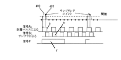
図1(c)に示すように、推定TOA104が実際のTOA106と異なり得るとき、サンプリングエラーが発生する場合がある。2点のサンプルポイント間のTOAを意味するサンプラの離散時間サンプリングステップおよび低時間分解能は識別されないであろう。つまり、精度はサンプリングレートにより制限されるのである。したがって、サンプリングレートが低くなればなるほど、サンプリングエラーの可能性も大きくなる。 As shown in FIG. 1C, when the estimated TOA 104 may be different from the actual TOA 106, a sampling error may occur. The sampler's discrete-time sampling step and low temporal resolution, meaning TOA between two sample points, will not be identified. That is, the accuracy is limited by the sampling rate. Therefore, the lower the sampling rate, the greater the possibility of sampling error.
従来技術において、様々なシステムが提案されてきた。例えば、米国特許第7171303号には測位システムが開示されており、それは共通クロックユニットを用いて、ローカル受信機と関連センサとの両方におけるサンプリング基準を形成する。ローカル受信機と関連センサとの両方は、測距処理中は同じ基準を有する。米国特許第7057553号には、GPS(global positioning system:全地球測位システム)において測位信号を処理する方法が開示されている。この方法は、測距受信機においていくつかの衛星から、測位信号からの疑似距離サンプルを収集する。米国特許第7042868号は、2つのパケット信号トランシーバ間における測距方法を開示する。2つのトランシーバ間の時間遅延および距離は、互いの送信および受信パケット信号を通して決定可能である。米国特許第6239741は、UWB対象検知のためのトンネルダイオード検知器を説明する。 Various systems have been proposed in the prior art. For example, US Pat. No. 7,171,303 discloses a positioning system that uses a common clock unit to form a sampling reference in both the local receiver and the associated sensor. Both the local receiver and the associated sensor have the same reference during the ranging process. US Pat. No. 7,057,553 discloses a method of processing positioning signals in a GPS (global positioning system). This method collects pseudorange samples from positioning signals from several satellites at a ranging receiver. U.S. Pat. No. 7,042,868 discloses a ranging method between two packet signal transceivers. The time delay and distance between the two transceivers can be determined through each other's transmitted and received packet signals. US Pat. No. 6,239,741 describes a tunnel diode detector for UWB object detection.
当発明者は、また、2006年6月23日に、時間‐電圧変換機を用いてTOAを推定する方法に関するシンガポール特許出願第200604221‐2を出願している。 The inventor has also filed Singapore Patent Application No. 200604221-2 on June 23, 2006 relating to a method for estimating TOA using a time-voltage converter.
一般的に言うと、本発明は、UWB信号が実際に受信されるときと受信UWB信号が始めてサンプリングされるときとの間の遅延を決定することに関する。サンプリング期間よりも小さいタイミングの違いが、あまり複雑なハードウェアを使用せずとも検知可能という利点、および/または高いサンプリングレートが必要ではないという利点を有することも、本発明は可能である。 Generally speaking, the present invention relates to determining the delay between when a UWB signal is actually received and when the received UWB signal is sampled for the first time. It is also possible for the present invention that timing differences smaller than the sampling period have the advantage that they can be detected without using very complex hardware and / or that a high sampling rate is not required.
本発明の一具体的顕現においては、対象までの距離を推定する方法であって、少なくとも1つのUWB信号を送信することと、少なくとも1つのUWB信号を受信することと、第1の周波数を有する複数のクロックおよび/またはサンプルパルスに依存して、受信されたUWB信号をサンプリングすることと、第1の周波数より低い第2の周波数、およびUWB信号が実際に受信されるときと受信されたUWB信号がはじめてサンプリングされるときとの間の遅延に依存する位相を有する非整数信号を与えることと、少なくとも、UWB信号の送信と受信との間のクロックまたはサンプルパルスの第1の数と、非整数信号の位相とに基づき、距離を決定することと、を含む方法が提供される。 In a specific manifestation of the present invention, a method for estimating a distance to an object comprising transmitting at least one UWB signal, receiving at least one UWB signal, and a first frequency Depending on the multiple clocks and / or sample pulses, sampling the received UWB signal, a second frequency lower than the first frequency, and when the UWB signal is actually received and the received UWB Providing a non-integer signal having a phase that depends on a delay between when the signal is first sampled, at least a first number of clocks or sample pulses between transmission and reception of the UWB signal, and non- Determining a distance based on the phase of the integer signal.
本発明の第2の独立の具体的顕現においては、対象までの距離を推定するシステムであって、少なくとも1つのUWB信号を送信する送信機と、少なくとも1つのUWB信号を受信する受信機と、第1の周波数を有する複数のクロックおよび/またはサンプルパルスに依存して、受信されたUWB信号をサンプリングするサンプラと、第1の周波数より低い第2の周波数、およびUWB信号が実際に受信されるときと受信されたUWB信号がはじめてサンプリングされるときとの間の遅延に依存する位相を有する非整数信号を生成し、少なくとも、UWB信号の送信と受信との間のクロックまたはサンプルパルスの第1の数と、非整数信号の位相とに基づき、距離を決定するように構成される回路および/またはプロセッサと、を備えるシステムが提供される。 In a second independent embodiment of the present invention, a system for estimating a distance to an object, wherein the transmitter transmits at least one UWB signal, and the receiver receives at least one UWB signal; Depending on a plurality of clocks and / or sample pulses having a first frequency, a sampler that samples the received UWB signal, a second frequency lower than the first frequency, and the UWB signal are actually received. Generating a non-integer signal having a phase that depends on the delay between when the received UWB signal is sampled for the first time and at least a first of a clock or sample pulse between the transmission and reception of the UWB signal A circuit and / or a processor configured to determine a distance based on the number of and the phase of the non-integer signal. Beam is provided.
発明の1または2以上の側面がより容易に理解され、実施されるように、非限定的例示により、本発明の1または2以上の実施形態を、添付図面に説明し参照しながらここで説明することとする。 In order that one or more aspects of the invention may be more readily understood and embodied, one or more embodiments of the invention will now be described by way of non-limiting illustration and with reference to the accompanying drawings in which: I decided to.
UWB信号のTOAを推定する実施形態の一例を図2に示す。システム200は、UWB信号を生成する送信機202と、反射UWB信号を受信する受信機204とを備える。概して、送信機202は参照信号を送出し、受信機204は目標対象物から反響参照信号を受信する。信号送信と信号受信との間の遅延を検知することにより、対象までの距離を見出すことが可能である。
An example of an embodiment for estimating the TOA of a UWB signal is shown in FIG.
クロック206が、送信機202へタイミングパルスを与え、送信機202は既定パターンにしたがって符号化パルスを生成する。反復パルス符号化が用いられるところで、最大遅延は時間領域においてUWBパルス符号長よりも長くあるべきではない。受信機204は整数遅延検知器208と非整数遅延検知器210とに接続される。整数遅延検知器208は、UWBパルス送信および反射UWBパルス受信間の整数クロックパルスの数を決定する。非整数遅延検知器210は、反射UWB信号の後の第1のクロックパルスが受信されるのと、反射UWB信号が実際に受信されるときとの間の遅延を決定する。
A
整数遅延検知208と非整数遅延検知210との間の関係を図3に示す。整数遅延306は、UWBパルス304が受信された後、UWBパルス302が第1のサンプル310へ送信されたとき300からの時間(クロックパルスまたはサンプルの数で測定)である。背景技術において説明したように、UWBパルス304はサンプル間において受信される場合がある。その結果、非整数遅延308は、UWBパルス304が受信された後、UWBパルス304が第1のサンプル310へ実際に受信されるとき312からの時間である。UWBパルスが受信される実際の時間312は、受信機204からの信号の包絡線が閾値を超えるときと決定されてもよい。
The relationship between
したがって全遅延すなわち実際のTOAは、整数遅延306から非整数遅延308を引くことにより計算可能である。測距計算(図2の212)は全遅延に基づく。
Thus, the total delay or actual TOA can be calculated by subtracting the
非整数遅延308を決定するために、非整数信号Fが生成される。非整数信号Fは、クロック周波数より低い周波数と、UWB信号が受信された後の第1のクロックまたはサンプルパルスと実際のUWB信号受信との間の遅延に依存する位相314とを有する。Fはサンプリング期間と比較してより大きい期間を有するため、反射UWBパルスが実際に受信されるときと、反射UWBパルスが受信されたあとの第1のサンプルとの間のタイミングにおける小さな関連変化は、より大きな変化をFの位相314にもたらすであろう。信号Fの位相は非整数遅延308の一時的拡張を表し、そのため非整数遅延308は、標準サンプリング周波数を用いて測定可能である。
To determine the
非整数遅延検知器210の方法の一例を図4に示す。2つの信号AおよびBが生成される。信号Aは、周波数ω0を有する受信UWBパルス400と同調し、周波数ω0はサンプリング周波数ω1よりも僅かに遅い。信号Bは、UWB信号が受信された後の第1のクロックまたはサンプルパルス402と同調し、サンプリング周波数ω1に等しい周波数を有する。
An example of the method of the
数式(1)に示すように信号AとBとを掛け合わせることにより、さらなる信号Cが生成される。
C=A(ω0)・B(ω1) ・・・(1)
By multiplying signals A and B as shown in equation (1), a further signal C is generated.
C = A (ω 0 ) · B (ω 1 ) (1)
信号Cは周波数領域において2部分に分けることができる。第1部の信号Dは、周波数ω0+ω1を中心とする高周波数部であり、第2部の信号Fは、周波数ω1−ω0を中心とする低周波部である。このように信号Cは、数式(2)に示すように表すこともできる。
C=D(ω0+ω1)+F(ω1−ω0) ・・・(2)
The signal C can be divided into two parts in the frequency domain. The signal D of the first part is a high frequency part centered on the frequency ω 0 + ω 1 , and the signal F of the second part is a low frequency part centered on the frequency ω 1 −ω 0 . Thus, the signal C can also be expressed as shown in Equation (2).
C = D (ω 0 + ω 1 ) + F (ω 1 −ω 0 ) (2)
信号DおよびFは大きく異なる周波数を有するため、低域通過フィルタを使用して、低周波数部F(ω1−ω0)を抽出してもよい。高周波数部D(ω0+ω1)は切捨ててもよい。 Since the signals D and F have significantly different frequencies, a low-pass filter may be used to extract the low frequency part F (ω 1 −ω 0 ). The high frequency part D (ω 0 + ω 1 ) may be discarded.
ω1がω0に近いため、信号F(ω1−ω0)は、サンプリング期間に比べ長い期間である。信号Fの位相は、UWB信号が受信された後の第1のクロックまたはサンプルパルスとUWB信号が受信されたときとの間の遅延にしたがって変化するであろう。したがって非整数308は、Fの位相314をサンプリングすることにより決定可能である。 Since ω 1 is close to ω 0 , the signal F (ω 1 −ω 0 ) is a longer period than the sampling period. The phase of signal F will change according to the delay between the first clock or sample pulse after the UWB signal is received and when the UWB signal is received. Thus, the non-integer 308 can be determined by sampling the phase 314 of F.
時間領域において非整数遅延308をF(ω1−ω0)の位相314へ拡張する乗数Kの因子が、数式(3)に示すように計算できる。
A factor of the multiplier K that extends the

例えば、サンプリング周波数ω1が100MHzであり、ω0が99MHzであるならば、F(ω1−ω0)はω1の1%の周波数、すなわち1MHzを有する。これにより、10nsの非整数遅延の可能な範囲(1サンプル期間)にわたる100個のサンプルの分解能が与えられる。これにより、比較的低速のサンプリング周波数を用いて、受信信号のみサンプリングする代わりにF(ω1−ω0)をサンプリングすることで、より高い時間分解能を得ることが簡単になる。上の例において、パルス到着時間検知の時間分解能は、10nsから100ps(10ns/100)まで2桁分の大きさだけ改善される。 For example, if the sampling frequency ω 1 is 100 MHz and ω 0 is 99 MHz, F (ω 1 −ω 0 ) has a frequency that is 1% of ω 1 , that is, 1 MHz. This gives a resolution of 100 samples over a possible range (1 sample period) of a non-integer delay of 10 ns. This makes it easier to obtain higher time resolution by sampling F (ω 1 −ω 0 ) instead of sampling only the received signal using a relatively low sampling frequency. In the above example, the time resolution of pulse arrival time detection is improved by a factor of two digits from 10 ns to 100 ps (10 ns / 100).
F(ω1−ω0)の期間、すなわち2π/(ω1−ω0)は、符号化パルスシーケンス期間よりも小さくなければならない。さもなければ、次に到来するパルス信号と重なってしまうため、F(ω1−ω0)は時間内に処理不可能である。 The period of F (ω 1 −ω 0 ), ie 2π / (ω 1 −ω 0 ), must be smaller than the encoded pulse sequence period. Otherwise, it overlaps with the next incoming pulse signal, so F (ω 1 −ω 0 ) cannot be processed in time.
例えば図5(a)〜(c)に示すように、Fの位相は非整数遅延に依存して変化する。図5(a)において、信号はサンプリングパルス同じ時刻に受信され(非整数遅延は零)、したがってFの位相は0°と示されている。図5(b)においては、小さい非整数遅延が存在し、したがってFの位相は90°である。図5(c)においては、大きい非整数遅延が存在し、したがってFの位相は180°である。 For example, as shown in FIGS. 5A to 5C, the phase of F changes depending on the non-integer delay. In FIG. 5 (a), the signal is received at the same time as the sampling pulse (non-integer delay is zero), so the phase of F is shown as 0 °. In FIG. 5 (b), there is a small non-integer delay, so the phase of F is 90 °. In FIG. 5 (c), there is a large non-integer delay, so the phase of F is 180 °.
UWB信号が送信されたときにカウンタ1を開始し、サンプリングされた受信信号が閾値(すなわちUWBパルスが受信された受信された後の第1のクロックパルス)よりも高いときにカウンタ1を停止することにより、整数遅延検知208は実施可能である。整数遅延τIは数式(4)にしたがって計算される。
τI=NI・T ・・・(4)
ここでNIはカウンタ1の値であり、Tはサンプル期間である。
Start
τ I = N I · T (4)
Where N I is the value of the
受信機からの信号の包絡線が閾値よりも高いときにカウンタ2を開始し、F(ω1−ω0)が状態を変化させる(すなわちクロックパルスの数がFの位相を表す)ときカウンタ2を停止することにより、非整数遅延検知210は実施可能である。非整数遅延τfは数式(5)にしたがって計算される。
τf=Nf・T/K ・・・(5)
ここでNfはカウンタ2の値である。したがって、全遅延すなわち実際のTOAΔは数式(6)にしたがって計算できる。
Δ=τI−τf ・・・(6)
Counter 2 is started when the envelope of the signal from the receiver is higher than the threshold, and counter 2 when F (ω 1 −ω 0 ) changes state (ie the number of clock pulses represents the phase of F). By stopping,
τ f = N f · T / K (5)
Here, N f is the value of the counter 2. Therefore, the total delay, ie the actual TOAΔ, can be calculated according to equation (6).
Δ = τ I −τ f (6)
全遅延すなわち実際のTOAΔは、距離または位置を計算するのに用いる場合がある。例えばUWB測距システムにおいては、数式(7)に示すように、発信信号と比較してトランシーバと対象との間の距離dは受信信号の遅延すなわち実際のTOAに比例する。
d=(Δ−X)・σ/2 ・・・(7)
ここでXは既知の不変回路遅延であり、σは、例えば光の速さなどのような伝達の速さである。
The total delay or actual TOAΔ may be used to calculate distance or position. For example, in the UWB ranging system, as shown in Equation (7), the distance d between the transceiver and the object is proportional to the delay of the received signal, that is, the actual TOA as compared with the outgoing signal.
d = (Δ−X) · σ / 2 (7)
Here, X is a known invariant circuit delay, and σ is a transmission speed such as the speed of light.
図6は非整数遅延検知210のハードウェアの実施形態を示している。信号A(ω0)およびB(ω1)が、2つのフィードバック振動回路600、608により生成される。
FIG. 6 illustrates a hardware embodiment of the
図6(a)において、第1の振動子回路600は、包絡線検知器(図2の214)の出力を受信し、受信された出力はラッチレジスタAのクロックインプットへ提供される。包絡線検知器214出力が閾値を上回る(UWBパルス到着を検知する)と、ラッチレジスタA出力606は高くなり、フィードバック振動子602を振動させる。振動の周波数はフィードバックライン604長により定められ、フィードバックライン604長はD0に設定され、これにより周波数はω0となる。F(ω1−ω0)が状態を変化させ、振動を停止させる場合、または次のパルスが到着した場合は、ラッチレジスタAは零にクリアされる。
In FIG. 6A, the
図6(b)において、第2の振動子回路608が信号B(ω1)を生成するのに使用される。ラッチレジスタAの出力606は、ANDゲート610においてクロックパルスと組み合わせられる。ANDゲート610の出力は、ラッチレジスタBのクロック入力へ提供される。UWBパルス到着後の第1のクロックパルスの後、ラッチレジスタB出力612は高くなる。これにより、フィードバック振動子614が振動させられる。振動の周波数はフィードバックライン616長により定められ、フィードバックライン616長はD1に設定され、これにより周波数はω1になる。この振動も、F(ω1−ω0)が状態を変化させたり、次のパルスが到着したりすると停止される。
In FIG. 6B, the
図6(c)に、さらなる回路616を示す。回路600、608からの信号A(ω0)およびB(ω1)は、ミキサまたは乗算と均等物であるXORゲート618へ送信され、信号Cとなる。XORゲート618からの信号CはラッチレジスタDのクロック出力へ与えられ、XORの結果をサンプリングしてホールドする。A(ω0)がラッチレジスタDのクロック入力へ提供され、そのため信号Cはω0においてサンプリングされ、登録される。この回路は低域通過フィルタと均等物であり、これにより出力において信号はF(ω1−ω0)となる。
A
本発明の好適な実施形態を詳細に説明してきたが、当業者には明らかなように、本発明の範囲内で多くの変更が可能である。 While the preferred embodiment of the present invention has been described in detail, many modifications are possible within the scope of the invention, as will be apparent to those skilled in the art.
Claims (15)
少なくとも1つのUWB信号を送信することと、
少なくとも1つのUWB信号を受信することと、
第1の周波数を有する複数のクロックおよび/またはサンプルパルスに依存して、受信された前記UWB信号をサンプリングすることと、
前記第1の周波数より低い第2の周波数、および前記UWB信号が実際に受信されるときと受信された前記UWB信号がはじめてサンプリングされるときとの間の遅延に依存する位相を有する非整数信号を与えることと、
少なくとも、前記UWB信号の送信と受信との間のクロックまたはサンプルパルスの第1の数と、前記非整数信号の位相とに基づき、距離を決定することと、
を含む方法。 A method for estimating a distance to an object,
Transmitting at least one UWB signal;
Receiving at least one UWB signal;
Sampling the received UWB signal in dependence on a plurality of clocks and / or sample pulses having a first frequency;
A non-integer signal having a second frequency lower than the first frequency and a phase dependent on the delay between when the UWB signal is actually received and when the received UWB signal is sampled for the first time And giving
Determining a distance based at least on the first number of clocks or sample pulses between transmission and reception of the UWB signal and the phase of the non-integer signal;
Including methods.
前記UWB信号が受信されると振動信号Aを開始することと、信号Aは、前記第1の周波数と等しい第3の周波数を有することと、
信号A開始後に前記第1のクロックまたはサンプルパルスが発生すると振動信号Bを開始することと、信号Bは、前記第3の周波数と比較して小さな周波数差を有する第4の周波数を有することと、
信号AとBとを掛け合わせ、信号Cを生成することと、
信号Cのより低い周波数成分を前記非整数信号として与えることと
を含む、請求項1または請求項2に記載の方法。 Giving the non-integer signal
Starting a vibration signal A when the UWB signal is received, the signal A having a third frequency equal to the first frequency;
Starting the vibration signal B when the first clock or sample pulse occurs after the start of the signal A, and the signal B has a fourth frequency having a small frequency difference compared to the third frequency; ,
Multiplying signals A and B to generate signal C;
Providing a lower frequency component of signal C as the non-integer signal.
τI=NI・T
に基づいて決定される、請求項6に記載の方法。 The integer delay is
τ I = N I · T
The method of claim 6, wherein the method is determined based on:
τf=Nf・T/K
に基づいて決定される、請求項7に記載の方法。 The non-integer delay is
τ f = N f · T / K
8. The method of claim 7, wherein the method is determined based on:
Δ=τI−τf
に基づいて決定される、請求項8に記載の方法。 The total delay or arrival time is
Δ = τ I −τ f
9. The method of claim 8, wherein the method is determined based on:
d=(Δ−x)・σ/2
に基づいて決定される、請求項9に記載の方法。 The distance is
d = (Δ−x) · σ / 2
The method of claim 9, wherein the method is determined based on:
少なくとも1つのUWB信号を送信する送信機と、
少なくとも1つのUWB信号を受信する受信機と、
第1の周波数を有する複数のクロックおよび/またはサンプルパルスに依存して、受信された前記UWB信号をサンプリングするサンプラと、
前記第1の周波数より低い第2の周波数、および前記UWB信号が実際に受信されるときと受信された前記UWB信号がはじめてサンプリングされるときとの間の遅延に依存する位相を有する非整数信号を生成し、少なくとも、前記UWB信号の送信と受信との間のクロックまたはサンプルパルスの第1の数と、前記非整数信号の位相とに基づき、距離を決定するように構成される回路および/またはプロセッサと
を備えるシステム。 A system for estimating the distance to an object,
A transmitter for transmitting at least one UWB signal;
A receiver for receiving at least one UWB signal;
A sampler that samples the received UWB signal in dependence on a plurality of clocks and / or sample pulses having a first frequency;
A non-integer signal having a second frequency lower than the first frequency and a phase depending on the delay between when the UWB signal is actually received and when the received UWB signal is sampled for the first time A circuit configured to determine a distance based on at least a first number of clocks or sample pulses between transmission and reception of the UWB signal and a phase of the non-integer signal and / or Or a system comprising a processor.
前記UWB信号が受信されると振動信号Aを開始し、信号Aは、前記第1の周波数に等しい第3の周波数を有し、
信号A開始後に前記第1のクロックまたはサンプルパルスが発生すると振動信号Bを開始し、信号Bは、前記第3の周波数と比較して小さな周波数差を有する第4の周波数を有し、
信号AとBとを掛け合わせ、信号Cを生成し、
信号Cのより低い周波数成分を前記非整数信号として与える
ように構成される、請求項12に記載のシステム。 The circuit and / or processor
When the UWB signal is received, it starts a vibration signal A, which has a third frequency equal to the first frequency;
When the first clock or sample pulse occurs after the start of the signal A, the vibration signal B is started, and the signal B has a fourth frequency having a small frequency difference compared to the third frequency,
Multiply signals A and B to generate signal C,
The system of claim 12, configured to provide a lower frequency component of signal C as the non-integer signal.
Applications Claiming Priority (1)
| Application Number | Priority Date | Filing Date | Title |
|---|---|---|---|
| SG200703957-1A SG148074A1 (en) | 2007-06-04 | 2007-06-04 | Ranging system and method |
Publications (1)
| Publication Number | Publication Date |
|---|---|
| JP2009002943A true JP2009002943A (en) | 2009-01-08 |
Family
ID=40088135
Family Applications (1)
| Application Number | Title | Priority Date | Filing Date |
|---|---|---|---|
| JP2008146793A Withdrawn JP2009002943A (en) | 2007-06-04 | 2008-06-04 | Distance measuring system and method |
Country Status (3)
| Country | Link |
|---|---|
| US (1) | US8054863B2 (en) |
| JP (1) | JP2009002943A (en) |
| SG (1) | SG148074A1 (en) |
Cited By (1)
| Publication number | Priority date | Publication date | Assignee | Title |
|---|---|---|---|---|
| WO2014153263A1 (en) * | 2013-03-14 | 2014-09-25 | Robert Ernest Troxler | Systems and methods for asphalt density and soil moisture measurements using ground penetrating radar |
Families Citing this family (2)
| Publication number | Priority date | Publication date | Assignee | Title |
|---|---|---|---|---|
| EP3438692A1 (en) * | 2017-08-03 | 2019-02-06 | Melexis Technologies NV | Sample-and-hold circuit for a lidar system |
| CN108777569A (en) * | 2018-05-23 | 2018-11-09 | 成都玖锦科技有限公司 | Arbitrary time-delay method based on multiphase filter |
Family Cites Families (18)
| Publication number | Priority date | Publication date | Assignee | Title |
|---|---|---|---|---|
| EP0249292A3 (en) * | 1986-06-10 | 1989-11-15 | THORN EMI Electronics Limited | Radio direction-finding using time of arrival measurements |
| US5519400A (en) * | 1993-04-12 | 1996-05-21 | The Regents Of The University Of California | Phase coded, micro-power impulse radar motion sensor |
| US6054950A (en) * | 1998-01-26 | 2000-04-25 | Multispectral Solutions, Inc. | Ultra wideband precision geolocation system |
| US6239741B1 (en) * | 1998-07-20 | 2001-05-29 | Multispectral Solutions, Inc. | UWB dual tunnel diode detector for object detection, measurement, or avoidance |
| US7110473B2 (en) * | 1998-12-11 | 2006-09-19 | Freescale Semiconductor, Inc. | Mode controller for signal acquisition and tracking in an ultra wideband communication system |
| US6925108B1 (en) * | 2000-05-26 | 2005-08-02 | Freescale Semiconductor, Inc. | Ultrawide bandwidth system and method for fast synchronization |
| US6914949B2 (en) * | 2000-10-13 | 2005-07-05 | Time Domain Corporation | Method and system for reducing potential interference in an impulse radio |
| US6717992B2 (en) * | 2001-06-13 | 2004-04-06 | Time Domain Corporation | Method and apparatus for receiving a plurality of time spaced signals |
| US6628234B2 (en) * | 2001-07-18 | 2003-09-30 | Fast Location.Net, Llc | Method and system for processing positioning signals in a stand-alone mode |
| EP1488559A2 (en) * | 2002-03-08 | 2004-12-22 | Xtremespectrum, Inc. | Method and system for performing ranging functions in an ultrawide bandwidth system |
| SE0300303D0 (en) * | 2003-02-06 | 2003-02-06 | Nordnav Technologies Ab | A navigation method and apparatus |
| CA2526133C (en) * | 2003-05-22 | 2012-04-10 | General Atomics | Ultra-wideband radar system using sub-band coded pulses |
| JP4519435B2 (en) * | 2003-09-25 | 2010-08-04 | 富士通コンポーネント株式会社 | In-vehicle system |
| US20050069052A1 (en) * | 2003-09-30 | 2005-03-31 | David Carbonari | Ultra-wideband receiver |
| JP4286629B2 (en) * | 2003-10-17 | 2009-07-01 | 富士通コンポーネント株式会社 | Pointing device and receiving unit |
| WO2005069905A2 (en) * | 2004-01-16 | 2005-08-04 | Ghz Tr Corporation | Methods and apparatus for automotive radar sensors |
| US20060106546A1 (en) * | 2004-11-17 | 2006-05-18 | Time Domain Corporation | System and method for evaluating materials using ultra wideband signals |
| WO2007011098A1 (en) | 2005-07-19 | 2007-01-25 | Electronics And Telecommunications Research Institute | High resolution ranging apparatus and method using uwb |
-
2007
- 2007-06-04 SG SG200703957-1A patent/SG148074A1/en unknown
-
2008
- 2008-06-04 US US12/132,776 patent/US8054863B2/en not_active Expired - Fee Related
- 2008-06-04 JP JP2008146793A patent/JP2009002943A/en not_active Withdrawn
Cited By (3)
| Publication number | Priority date | Publication date | Assignee | Title |
|---|---|---|---|---|
| WO2014153263A1 (en) * | 2013-03-14 | 2014-09-25 | Robert Ernest Troxler | Systems and methods for asphalt density and soil moisture measurements using ground penetrating radar |
| US10145837B2 (en) | 2013-03-14 | 2018-12-04 | Robert Ernest Troxler | Systems and methods for asphalt density and soil moisture measurements using ground penetrating radar |
| US11346835B2 (en) | 2013-03-14 | 2022-05-31 | International Research Institute CiRI | Systems and methods for asphalt density and soil moisture measurements using ground penetrating radar |
Also Published As
| Publication number | Publication date |
|---|---|
| US20080298432A1 (en) | 2008-12-04 |
| US8054863B2 (en) | 2011-11-08 |
| SG148074A1 (en) | 2008-12-31 |
Similar Documents
| Publication | Publication Date | Title |
|---|---|---|
| US8395543B2 (en) | Method and apparatus for mitigating multipath effects at a satellite signal receiver using a sequential estimation filter | |
| EP2058670B1 (en) | Suppression of multipath effects for received SPS signal | |
| JP4842127B2 (en) | Method for estimating arrival time of signal received in TH-UWB system by two-step estimation method | |
| US20120319898A1 (en) | Method of detecting multipath, gnss receiving apparatus , and mobile terminal | |
| WO2013010123A1 (en) | System and method for enhanced point-to-point direction finding | |
| JP6324327B2 (en) | Passive radar equipment | |
| US10191158B2 (en) | GNSS receiver calculating a non-ambiguous discriminator to resolve subcarrier tracking ambiguities | |
| RU2507536C1 (en) | Coherent pulsed signal measuring detector | |
| JP2009002943A (en) | Distance measuring system and method | |
| JP2019023577A (en) | System and method for moving target detection | |
| JP2007240485A (en) | Pulse radar system and distance measuring method | |
| WO2011010100A1 (en) | Measurement method and apparatus | |
| WO2013140911A1 (en) | Signal search method, signal search program, signal search device, global navigation satellite system (gnss) signal receiver, and information terminal | |
| US20070139265A1 (en) | Method of acquiring satellite data | |
| JP4777353B2 (en) | GPS positioning method and GPS positioning device | |
| EP2913690B1 (en) | Positioning system and method | |
| US10495727B2 (en) | Phase difference estimator and method for estimating a phase difference between signals | |
| US20030157886A1 (en) | Computing network path delays so accurate absolute time can be forwarded from a server to a client | |
| RU2293997C1 (en) | Method for correlation processing of signals, reflected from fast-moving targets | |
| JP2007278708A (en) | Satellite navigation system | |
| JP2009122045A (en) | Positioning device | |
| RU2589036C1 (en) | Radar with continuous noise signal and method of extending range of measured distances in radar with continuous signal | |
| JP2009168451A (en) | Positioning apparatus | |
| WO2013140910A1 (en) | Signal search method, signal search program, signal search device, global navigation satellite system (gnss) signal receiver, and information terminal | |
| Zhang et al. | GNSS spoofing localization based on differential code phase |
Legal Events
| Date | Code | Title | Description |
|---|---|---|---|
| A300 | Application deemed to be withdrawn because no request for examination was validly filed |
Free format text: JAPANESE INTERMEDIATE CODE: A300 Effective date: 20110906 |