JP2008541788A - Implantable lens with modified edge region - Google Patents
Implantable lens with modified edge region Download PDFInfo
- Publication number
- JP2008541788A JP2008541788A JP2008506804A JP2008506804A JP2008541788A JP 2008541788 A JP2008541788 A JP 2008541788A JP 2008506804 A JP2008506804 A JP 2008506804A JP 2008506804 A JP2008506804 A JP 2008506804A JP 2008541788 A JP2008541788 A JP 2008541788A
- Authority
- JP
- Japan
- Prior art keywords
- lens
- region
- boundary surface
- distance
- edge
- Prior art date
- Legal status (The legal status is an assumption and is not a legal conclusion. Google has not performed a legal analysis and makes no representation as to the accuracy of the status listed.)
- Pending
Links
Images


Classifications
-
- A—HUMAN NECESSITIES
- A61—MEDICAL OR VETERINARY SCIENCE; HYGIENE
- A61F—FILTERS IMPLANTABLE INTO BLOOD VESSELS; PROSTHESES; DEVICES PROVIDING PATENCY TO, OR PREVENTING COLLAPSING OF, TUBULAR STRUCTURES OF THE BODY, e.g. STENTS; ORTHOPAEDIC, NURSING OR CONTRACEPTIVE DEVICES; FOMENTATION; TREATMENT OR PROTECTION OF EYES OR EARS; BANDAGES, DRESSINGS OR ABSORBENT PADS; FIRST-AID KITS
- A61F2/00—Filters implantable into blood vessels; Prostheses, i.e. artificial substitutes or replacements for parts of the body; Appliances for connecting them with the body; Devices providing patency to, or preventing collapsing of, tubular structures of the body, e.g. stents
- A61F2/02—Prostheses implantable into the body
- A61F2/14—Eye parts, e.g. lenses, corneal implants; Implanting instruments specially adapted therefor; Artificial eyes
- A61F2/16—Intraocular lenses
-
- A—HUMAN NECESSITIES
- A61—MEDICAL OR VETERINARY SCIENCE; HYGIENE
- A61F—FILTERS IMPLANTABLE INTO BLOOD VESSELS; PROSTHESES; DEVICES PROVIDING PATENCY TO, OR PREVENTING COLLAPSING OF, TUBULAR STRUCTURES OF THE BODY, e.g. STENTS; ORTHOPAEDIC, NURSING OR CONTRACEPTIVE DEVICES; FOMENTATION; TREATMENT OR PROTECTION OF EYES OR EARS; BANDAGES, DRESSINGS OR ABSORBENT PADS; FIRST-AID KITS
- A61F2/00—Filters implantable into blood vessels; Prostheses, i.e. artificial substitutes or replacements for parts of the body; Appliances for connecting them with the body; Devices providing patency to, or preventing collapsing of, tubular structures of the body, e.g. stents
- A61F2/02—Prostheses implantable into the body
- A61F2/14—Eye parts, e.g. lenses, corneal implants; Implanting instruments specially adapted therefor; Artificial eyes
- A61F2/147—Implants to be inserted in the stroma for refractive correction, e.g. ring-like implants
-
- B—PERFORMING OPERATIONS; TRANSPORTING
- B29—WORKING OF PLASTICS; WORKING OF SUBSTANCES IN A PLASTIC STATE IN GENERAL
- B29D—PRODUCING PARTICULAR ARTICLES FROM PLASTICS OR FROM SUBSTANCES IN A PLASTIC STATE
- B29D11/00—Producing optical elements, e.g. lenses or prisms
- B29D11/00009—Production of simple or compound lenses
- B29D11/00028—Bifocal lenses; Multifocal lenses
-
- B—PERFORMING OPERATIONS; TRANSPORTING
- B29—WORKING OF PLASTICS; WORKING OF SUBSTANCES IN A PLASTIC STATE IN GENERAL
- B29D—PRODUCING PARTICULAR ARTICLES FROM PLASTICS OR FROM SUBSTANCES IN A PLASTIC STATE
- B29D11/00—Producing optical elements, e.g. lenses or prisms
- B29D11/02—Artificial eyes from organic plastic material
- B29D11/023—Implants for natural eyes
-
- G—PHYSICS
- G02—OPTICS
- G02C—SPECTACLES; SUNGLASSES OR GOGGLES INSOFAR AS THEY HAVE THE SAME FEATURES AS SPECTACLES; CONTACT LENSES
- G02C7/00—Optical parts
- G02C7/02—Lenses; Lens systems ; Methods of designing lenses
Abstract
【解決手段】本明細書にて説明した植込み型レンズは、改変した端縁領域を提供する。一例としての実施の形態において、植込み型レンズは、前面と、後面と、前面及び後面を分離する外端縁面とを含む。前面は、矯正部分と、斜角付き部分とを含むことができる。斜角付き部分は、矯正部分と外端縁面との間に配置することができる。外端縁面は、第一の部分と、第二の部分とを有することができ、第一の部分は後面及び前面と当接し、第二の部分斜角付き部分と更に当接する。改変した端縁領域は、前面と後面との間にてより漸進的な転位部を提供する。
【選択図】図3The implantable lens described herein provides a modified edge region. In an exemplary embodiment, the implantable lens includes a front surface, a rear surface, and an outer edge surface that separates the front and rear surfaces. The front surface can include a correction portion and a beveled portion. The beveled portion can be disposed between the correction portion and the outer edge surface. The outer edge surface can have a first portion and a second portion, the first portion abutting the rear surface and the front surface and further abutting the second partially beveled portion. The modified edge region provides a more gradual dislocation between the front and back surfaces.
[Selection] Figure 3
Description
本発明の分野は、全体として、植込み型レンズ、より具体的には、端縁領域が改変された植込み型レンズに関する。 The field of the invention relates generally to implantable lenses, and more specifically to implantable lenses with modified edge regions.
周知であるように、人間の眼の異常は、視覚障害に到る可能性がある。ある典型的な異常は、近視、遠視及び乱視に到る可能性のある眼の形状の変化及び老眼に到る可能性のある水晶体の弾性の低下のような、眼全体に渡って存在する組織の変化を含む。一般に、植込み型レンズと称される特定の装置は、上記及びその他の視覚障害を成功裏に治療するため使用されている。 As is well known, abnormalities in the human eye can lead to visual impairment. Some typical abnormalities are tissue that exists throughout the eye, such as changes in the shape of the eye that can lead to myopia, hyperopia and astigmatism and loss of lens elasticity that can lead to presbyopia. Including changes. In general, certain devices, referred to as implantable lenses, have been used to successfully treat these and other visual disorders.
植込み型レンズは、典型的に、眼の自然の水晶体に置換するため眼内に深く植え込むことのできる眼内レンズ(IOLs)と、典型的に、入射光を変化させ得るように角膜内にて眼の表面付近に植え込まれる角膜インプラントという、2種類の1つに属する。一方、角膜インプラントは、アンレー(onlay)又はインレー(inlay)に区分することができる。アンレーは、例えば、上皮のような角膜の外層がインプラントの上にて成長し且つインプラントを取り囲むように、角膜上に配置されるインプラントである。インレーは、例えば、ケラトフィケア(keratophakia)を使用して角膜組織の一部分の下方にて角膜内に外科的に植え込まれるインプラントである。角膜インレーを植え込む一例としての方法は、その内容の全体を参考として引用し本明細書に含めた、2004年、8月23日付けで出願された、同時出願係属中の米国特許出願明細書10/924,152号に更に詳細に記載されている。
Implantable lenses are typically intraocular lenses (IOLs) that can be implanted deep into the eye to replace the natural lens of the eye, and typically within the cornea so that incident light can be altered. It belongs to one of two types: corneal implants implanted near the surface of the eye. On the other hand, corneal implants can be divided into onlays or inlays. An onlay is an implant that is placed on the cornea such that, for example, the outer layer of the cornea, such as the epithelium, grows on and surrounds the implant. An inlay is an implant that is surgically implanted in the cornea below a portion of corneal tissue using, for example, keratofakia. An exemplary method of implanting a corneal inlay is described in co-pending US
角膜インプラントは、角膜組織中に配置されるため、組織がインプラントに対して好ましくなく反応して望ましくない状態を形成するのを防止することに顕著な関心が持たれる。例えば、細胞の分泌及び角膜実質細胞の蓄積といったような特定の好ましくない組織の反応は、角膜の濁りと称される望ましくない状態を引き起こす可能性がある。角膜の濁りは、光が角膜及びインプラントを通って進むのを妨害し、これにより、視覚障害を適正に治療することを妨げる。角膜の濁りは、多数の作用を及ぼすが、これは、少なくとも部分的に、角膜組織内にて角膜実質細胞上に加えられた機械的力による影響を受ける可能性があることの証拠がある。 Because corneal implants are placed in corneal tissue, there is significant interest in preventing the tissue from undesirably reacting to the implant to form an undesirable state. For example, certain undesirable tissue reactions, such as cell secretion and keratocyte accumulation, can cause an undesirable condition called corneal turbidity. Corneal haze prevents light from traveling through the cornea and implant, thereby preventing proper treatment of visual impairment. Corneal turbidity has numerous effects, but there is evidence that it can be influenced, at least in part, by mechanical forces applied on corneal parenchymal cells within the corneal tissue.
更に、幾つかを挙げれば、非球形のインプラント及び浅い球形のインプラントのような、外端縁の回りにて比較的平坦である一部の角膜インプラントは、端縁の持ち上がりという欠点がある。端縁の持ち上がりは、外端縁の回りのインプラントの前面が頂点に向けて湾曲し又は後方に持ち上がるときに生じる。図1は、図示する目的のため、誇張して示した、端縁の持ち上がりという欠点を有する従来の角膜インプラント20の断面図である。この場合、インプラント20は、外端縁21と、前面22と、頂点23と、後面24とを有している。理想的な端縁の輪郭外形は破線10で示されている。理想的な場合、前面22における最後方点は、外端縁21上に配置されている。しかし、端縁の持ち上がりという欠点を有するレンズにおいて、前面22の最後方点は、外端縁21よりも頂点23に近い位置24に配置することがある。端縁の持ち上がりは、時間−遺伝のため、進行し且つ累積し、その結果、光学的性能は劣化し、また、植込み過程をより困難なものとする可能性がある。
Furthermore, some corneal implants that are relatively flat around the outer edge, such as non-spherical and shallow spherical implants, have the disadvantage of edge lifting. Edge lift occurs when the anterior surface of the implant around the outer edge curves toward the apex or lifts back. FIG. 1 is a cross-sectional view of a conventional
従って、レンズの存在に対する望ましくない生理学的応答を減少させると共に、端縁の持ち上がりというリスクを減少させる改良された植込み型レンズが必要とされている。 Accordingly, there is a need for an improved implantable lens that reduces the undesirable physiological response to the presence of the lens and reduces the risk of edge lift.
植込み型レンズ及び植込み型レンズを製造する方法の実施の形態は、単に一例として且つ、本発明を限定することを意図せずに、本明細書に記載されている。一例としての実施の形態において、前面と、後面と、前面と後面との間に配置された端縁面とを有するレンズ本体を備える植込み型レンズが提供される。前面は、矯正部分と、矯正部分と端縁面との間に配置された斜角付き部分とを含む。斜角付き部分は、第一の境界面にて矯正部分と当接し、また、第二の境界面にて端縁面と当接し、斜角付き部分は、第一の境界面と第二の境界面との間にて平坦又は湾曲し又は任意のその他の望ましい形状とすることができる。端縁面は、第三の境界面にて斜角付き部分と当接し、また、第四の境界面にて後面と当接することができ、また、第三の境界面と第四の境界面との間にて平坦又は湾曲し又は任意のその他の望ましい形状とすることができる。端縁面は、第三の境界面にて斜角付き部分と当接する第一の部分と、第四の境界面にて後面と当接する第二の部分とを含むことができ、第一の部分は第五の境界面にて第二の部分と当接する。端縁面の第一の部分は、平坦とし、湾曲し又は任意のその他の望ましい形状とすることができ、また、第三の境界面から第五の境界面まで後面に向けて収斂することができる。端縁面の第二の部分は、第四の境界面と第五の境界面との間にて平坦とし、湾曲し又は任意のその他の望ましい形状とすることができる。 Embodiments of the implantable lens and the method of manufacturing the implantable lens are described herein by way of example only and without intending to limit the invention. In an exemplary embodiment, an implantable lens is provided that includes a lens body having a front surface, a rear surface, and an edge surface disposed between the front and rear surfaces. The front surface includes a correction portion and a beveled portion disposed between the correction portion and the edge surface. The beveled portion is in contact with the correction portion at the first boundary surface, and is in contact with the edge surface at the second boundary surface, and the beveled portion is in contact with the first boundary surface and the second boundary surface. It can be flat or curved between the interface and any other desired shape. The edge surface can be in contact with the beveled portion at the third boundary surface, can be in contact with the rear surface at the fourth boundary surface, and can be contacted with the third and fourth boundary surfaces. Can be flat or curved or any other desired shape. The edge surface may include a first portion that contacts the beveled portion at the third boundary surface and a second portion that contacts the rear surface at the fourth boundary surface, The part contacts the second part at the fifth boundary surface. The first portion of the edge surface may be flat, curved or any other desired shape and may converge toward the rear surface from the third interface surface to the fifth interface surface. it can. The second portion of the edge surface can be flat, curved or any other desired shape between the fourth and fifth interface surfaces.
別の一例としての実施の形態において、第一の領域と、第二の領域とを有し、第一の領域は、第一の屈折率を有し、第二の領域は、第一の屈折率と異なる第二の屈折率を有する、本体を備える植込み型レンズが提供される。第一の領域は、本体に隣接する組織を実質的に維持するのに十分な量の流体及び栄養物に対して透過可能である。第二の領域は、第一の領域と同一の透過率を有することができ、又は、第二の領域は、第一の領域よりも相対的に低透過性率であるようにすることができる。第一及び第二の領域は、望まれる任意の距離を渡って屈折率の矯正効果(すなわち、近/遠、遠/近等)を提供することができ、また、任意の望ましい態様にて配置することができる。レンズは、望まれる任意の曲率を有する前面を備え、また、角膜インレー又はアンレーとして形成することができる。別の一例としての実施の形態において、第一の領域は、第一の重合系材料から成るものとし、また、第二の領域は、第二の重合系材料から成るものとすることができ、第一及び第二の領域は、互いに一体的に連結される。所望に応じて、2つ又はより多くの任意の数の領域を含め、1つ又はより多くの領域が互いに一体的に連結されるようにすることができる。 In another exemplary embodiment, the first region has a second region, the first region has a first refractive index, and the second region has a first refraction. An implantable lens with a body having a second refractive index different from the index is provided. The first region is permeable to a sufficient amount of fluid and nutrients to substantially maintain the tissue adjacent to the body. The second region can have the same transmittance as the first region, or the second region can be relatively less permeable than the first region. . The first and second regions can provide a refractive index correction effect (ie, near / far, far / near, etc.) over any desired distance, and can be arranged in any desired manner. can do. The lens has a front surface with any desired curvature and can be formed as a corneal inlay or onlay. In another exemplary embodiment, the first region may comprise a first polymeric material and the second region may comprise a second polymeric material, The first and second regions are integrally connected to each other. If desired, one or more regions can be integrally connected to each other, including any number of two or more regions.
また、植込み型レンズを製造する一例としての方法も提供され、この方法は、第一の屈折率を有する第一のポリマーを備える第一のコアを形成するステップと、第一のコアの少なくとも一部分の回りに境界面領域を形成するステップと、境界面領域の少なくとも一部分の回りに第一の屈折率と異なる第二の屈折率を有する第二のポリマーを備える、第二のコアを形成するステップと、第一及び第二のコアから植込み型レンズを形成するステップとを備えている。境界面領域は、また、第一のポリマーと第二のポリマーとの混合体を含むことができ、また、第一及び第二の屈折率と異なる第三の屈折率を有し且つ追加的な屈折率の矯正効果を提供し又は、第一の重合系領域と第二の重合系領域との間の漸進的な転位部として作用することができる。境界面領域は、第一のコアと第二のコアとを互いに一体的に連結し且つ、第一のポリマーと第二のポリマーとの互いに侵入する回路網を含むことができる。 An example method of manufacturing an implantable lens is also provided, the method comprising forming a first core comprising a first polymer having a first refractive index, and at least a portion of the first core. Forming an interface region around and forming a second core comprising a second polymer having a second refractive index different from the first refractive index around at least a portion of the interface region And forming an implantable lens from the first and second cores. The interface region can also include a mixture of the first polymer and the second polymer, and has a third refractive index that is different from the first and second refractive indexes, and an additional It can provide a refractive index correction effect or act as a gradual dislocation between the first polymerized region and the second polymerized region. The interface region may include a network that integrally connects the first core and the second core to each other and that penetrates the first polymer and the second polymer.
一例としての方法は、第一のコアと接触する状態にて単量体溶液を配置するステップを含むことができ、この場合、第一のポリマーは、単量体溶液中にて溶融することができ、第一のコアの一部分を単量体溶液中にて溶解させ、単量体溶液及び溶解した第一のコアの部分が境界面領域内にて混合するようにするステップと、単量体溶液と第一のコアの溶解した部分との混合体を境界面領域内にて重合化するステップとを含むこともできる。 An exemplary method can include placing a monomer solution in contact with a first core, where the first polymer can be melted in the monomer solution. Allowing a portion of the first core to be dissolved in the monomer solution such that the monomer solution and the dissolved first core portion are mixed within the interface region; Polymerizing the mixture of solution and dissolved portion of the first core within the interface region.
別の実施の形態において、第一の非球面性(Q)を有する第一の実質的に非球形面と、第一の非球面性と異なる第二の非球面性(Q)を有する第二の実質的に非球形面とを含む本体を備える植込み型レンズが提供される。第一及び第二の非球形面は、眼から任意の望まれる距離又は距離の範囲内にて視力を助け得るような形態とすることができ、また、望まれる任意の態様にて配置することができる。 In another embodiment, a first substantially aspheric surface having a first asphericity (Q) and a second having a second asphericity (Q) different from the first asphericity. An implantable lens is provided that includes a body that includes a substantially non-spherical surface. The first and second non-spherical surfaces can be configured to aid vision at any desired distance or range of distances from the eye and are arranged in any desired manner. Can do.
本発明のその他のシステム、方法、特徴及び有利な効果は、以下の図面及び詳細な説明を検討することにより、当該技術の当業者に明らかになるであろう。本明細書に含めた、かかる追加的なシステム、方法、特徴及び有利な効果の全ては、本明細書に含め、本発明の範囲とし、また、請求の範囲により保護されることを意図するものである。また、本発明は、一例としての実施の形態の詳細に限定されることを意図するものではない。 Other systems, methods, features and advantages of the present invention will become apparent to those skilled in the art upon review of the following drawings and detailed description. All such additional systems, methods, features and advantages included herein are intended to be included within the scope of this invention and protected by the following claims. It is. In addition, the present invention is not intended to be limited to the details of the exemplary embodiment.
製造、構造及び作用を含む、本発明の詳細は、同様の部分を同様の参照番号にて表示する、添付図面を検討することにより理解することができよう。
レンズに近接して望ましくない組織の反応の刺激を減少させることのできる改変した端縁領域を有する改良された植込み型レンズが本明細書に記載されている。図2Aないし図2Eには、植込み型レンズ100の一例としての各種の実施の形態が示されている。図2Aは、植込み型レンズ100示す斜視図であり、ここで、レンズ100は、レンズ本体101と、前面102と、後面103と、外端縁面104とを有している。図2Bは、方向110で見たときのレンズ100の頂面図である。この場合、レンズ本体101は、前面102の最前方点を表現する中央頂点105を有する、全体として、円形の輪郭外形119を有している。直径部112は、レンズ本体101の全直径を表し、直径部114は、1つ又はより多くの特定の視覚障害を矯正し得るような形態とされた前面102の部分である、矯正部分122の直径を表す。
Details of the invention, including manufacture, structure and operation, may be understood by studying the accompanying drawings, in which like parts are labeled with like reference numerals.
Described herein are improved implantable lenses having modified edge regions that can reduce the stimulation of undesirable tissue responses proximate to the lens. Various embodiments as an example of the
図2Cは、図2Bの線1−1に沿ったレンズ100の断面図である。この図から、前面102は、頂点105と交差する中心軸線118に位置する頂点108から測定した曲率半径106を有して実質的に球形である。同様に、後面103は、また、頂点109から測定したそれ自体の曲率半径107を有している。レンズ100の矯正倍率は、これらの半径106−107に依存し、半径106−107の何れかを調節することにより望むよう変化させることができる。また、この場合、レンズ100は、遠視を矯正し得る形態とされている、すなわち、後面103に対する前面102の関係は、レンズ本体101に対し、線1−1に沿って収斂するメニスカス様形状を与える。中心軸線118に沿ったレンズ本体101の厚さは、中心厚さ140と称する。
2C is a cross-sectional view of
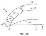
図2Dは、図2Cの領域111を更に詳細に示す、レンズ100の拡大断面図である。図2Dにおいて、前面102の矯正部分122は、実質的に球形であり、前面102は、また、斜角付き部分124を有している。この場合、斜角付き部分124は、単一の曲率半径にて湾曲しており、斜角半径124と称する。本明細書にて使用するように、「斜角」とは、平坦面、湾曲面及び任意のその他の形状の面を含むことを意図するものである。斜角半径124は、境界面123にて球形部分122と当接する。斜角半径124に隣接して、外端縁面104があり、斜角半径124と外端縁面104との間の当接部は、境界面125と称する。外端縁面104は、境界面127にて互いに当接する第一の部分126と、第二の部分128とを含む。第二の端縁面部分128は、境界面129にて後面103と当接する。この場合、第一の端縁面部分126は、湾曲しており、端縁半径126と称する。この実施の形態において、端縁厚さ130は、レンズ本体101の最後方点(この場合、境界面129)からZ方向への第二の端縁面部分128の高さとして規定される。
FIG. 2D is an enlarged cross-sectional view of the
図2Eは、端縁半径126の傾斜を画成する端縁半径の傾斜角度132を有する図2Dの一例としての実施の形態を示す領域111の別の断面図である。端縁半径の傾斜角度132は、軸線131、133の間の角度として規定することができる。この場合、軸線131は、中心軸線118に対して平行であり且つ、境界面125と交差する一方、軸線133は、境界面125、127と交差する。斜角半径124の傾斜を画成する斜角半径の傾斜角度135も示されている。斜角半径の傾斜角度135は、軸線134、136の間の角度として規定することができる。この場合、軸線134は、中心軸線118に対して平行であり且つ、境界面123と交差し、また、軸線136は、境界面123、125と交差する。
FIG. 2E is another cross-sectional view of region 111 showing an example embodiment of FIG. 2D having an edge
図2Dないし図2Eに示すように、端縁半径126は、斜角半径124よりも大きい角度までZ方向に傾斜することが好ましく、端縁半径126は、斜角半径124よりも大きい率にて後面103に向けて収斂する。傾斜角度にて説明すれば、端縁半径の傾斜角度132は、斜角半径の傾斜角度135よりも小さいことが好ましい。その結果、レンズ100は、端縁の持ち上がりが生じ難い。また、球形部分122と後面103との間の漸進的な転移部分は、レンズ100に対する好ましくない組織の反応の刺激を減少させることができる。
As shown in FIGS. 2D-2E, the
例えば、図3は、レンズ202、眼房水203、毛様体204、虹彩205、レンズ100の一例としての実施の形態がその内部に植え込まれた角膜206を含む人間の眼の前部分を示す断面図である。この場合、レンズ100は、角膜インレーとして植え込んだ状態にて示されているが、レンズ100は、角膜206の前面に近い位置にて角膜アンレーとして植え込むこともできることを認識すべきである。レンズ100の端縁領域における漸進的な転位は、前面と後面との間の斜角無しの鋭角な又は急峻な転移部分を有する従来のレンズよりも、取り囲む角膜組織207がレンズ100を受け入れることをより容易にする。その結果、レンズ100は、角膜の濁り及び同様のもののような、望ましくない状態を生じ難い。更に、植え込む手順の間、レンズ100の改変した端縁領域は、レンズ100が適正に向き決めされているかどうか又はレンズ100が上下逆さであるかどうかを確認することを容易にする。
For example, FIG. 3 shows a front portion of a human eye that includes a
角膜206を支え且つ、組織の壊死を防止するため、角膜206内にて流体及び栄養物の十分な移動レベルを維持しなければならない。従って、レンズ本体101は、前面102及び後面103に隣接する角膜組織207の間にて流体及び栄養物が移動することを許容するのに十分な透過性を有する材料から成り、望ましい時間に渡って角膜を支えることができることが好ましい。例えば、一例として実施の形態において、レンズ本体101は、微孔性ヒドロゲル材料から成っている。細孔性ヒドロゲルは、その内容の全体を参考として引用し本明細書に含めた、「角膜インプラント及び製造方法(Corneal Implant and Method of Manufacture)」という名称の米国特許明細書6,875,232号に更に詳細に記載されている。
Sufficient fluid and nutrient migration levels within the
表1には、所定のジオプター(diopter)を有する5.0ミリメートル(mm)直径のレンズ100の1つの実施の形態に対する一例としての値が示されている。これらの一例としての値は、単に説明の目的のためであり、植込み型レンズ100をこれらの値又は同様の値に何ら限定するものではない。
Table 1 shows exemplary values for one embodiment of a 5.0 millimeter (mm)

端縁厚さ130、端縁半径126、端縁傾斜角度132及び斜角半径124の値は、相互に依存し、また、望まれる矯正値、全体的なレンズ直径112、矯正部分122の直径、前面102及び後面103の形状に基づくものである。好ましくは、レンズ直径112が約1ないし10mmで矯正部分の直径114が約0.5mm以上のものは、端縁厚さが約0.015mm以下、端縁半径126が約0.001ないし1mmの範囲、端縁傾斜角度132が約0ないし90°の範囲、斜角半径124が約1ないし10mmの範囲となるであろう。これらの範囲は、単に説明の目的のためであり、本明細書に記載した実施の形態を何ら限定するものではない。
The values of
本明細書に記載した改変した端縁は、任意の型式、形状、又は形態の植込み型レンズと共に使用することができることを認識すべきである。例えば、レンズ100は、角膜インレー又はアンレーの何れかとすることができる。レンズ100は、近視、遠視、乱視及び老眼を含むが、これらにのみ限定されない任意の視覚障害を治療する形態とすることができる。レンズ100は、また、近視又は遠視を伴なう老眼、又は乱視を伴なう老眼を含むが、これらのみ限定されない視覚障害の任意の組み合わせを治療する形態とすることもできる。レンズ100の全体的な輪郭外形119は、円形、楕円形、不規則形、多面体、及び内側開口を有する形状を含むが、これらにのみ限定されない任意の形状とすることができる。外端面104は、固定要素及び同様のもののような、露頭部を有する形態とすることができる。また、レンズ本体101は、任意の望ましい屈折率を有する1つ又はより多くの異なる材料にて製造することができる。更に、以下に更に詳細に説明するように、前面102の矯正部分122は、多焦点領域を有し又は有しない実質的に球形とし、多重非球形面を有し又は有しない実質的に非球形とし、又は任意の組み合わせ又は同様のものとすることができる。本明細書にて使用するように、実質的にという語は、改変した語を拡大することを意図するものである。例えば、実質的に球形面は、完全に球形である必要はなく、実施するのに十分な程度の非球面的変化又は誤り及び同様のものを含むことができる。
It should be appreciated that the modified edge described herein can be used with any type, shape, or form of implantable lens. For example, the
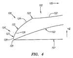
図4ないし図9は、図1Bの領域111内にて線1−1に沿った、レンズ100の追加的な一例としての実施の形態を示す断面図である。図4に示した実施の形態において、前面102の矯正部分122は、実質的に非球形である。非球形面の曲率は、典型的に、表面が外端縁面104に向けて外方に累進するに伴ない、減少し又は増大する。この実施の形態において、非球形面122の曲率は、減少し、このため、表面は、頂点105(図示せず)付近よりも外端縁面104付近にてより平坦である。前面102及び後面103は、面102−103が頂点105(図示せず)から境界面123に向けて半径方向外方に進行するに伴ない、拡張する。境界面123から境界面125まで、斜角半径124は、後面103に向けて収斂することが好ましい。同様に、境界面125から境界面127まで、端縁半径126は、後面103に向けて収斂することが好ましい。
4-9 are cross-sectional views illustrating additional exemplary embodiments of
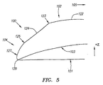
前面102の斜角付き部分124は、平坦、又は湾曲し、あるいは、任意のその他の望ましい形状とすることができる。例えば、図2Cないし2Eにおいて、斜角付き部分124は、球状に湾曲しているが、任意の型式の曲線部を使用することが可能なことを認識すべきである。図5に示した実施の形態において、斜角付き部分124は平坦である。同様に、第一及び第二の端縁面部分126、128は、平坦又は湾曲し、あるいは、その他の望ましい形状とすることができる。例えば、図2Cないし図2Eにおいて、端縁半径126は、実質的に球状に湾曲し、また、第二の端縁面部分128は可変の率にて湾曲している。図6に示した実施の形態において、第一の端縁面部分126は平坦である一方、図7の実施の形態において、第二の端縁面部分128は平坦である。平坦面と湾曲面の任意の組み合わせが実施可能である。例えば、図8において、斜角付き部分124、第一及び第二の端縁面部分126、128は全て平坦である。また、端縁面104は、任意の望ましい態様にて実施可能である。例えば、図9において、端縁面104は、平坦であり且つ、Z方向にのみ向き決めされている。
The
図10Aは、リング状の形状を有するレンズ100の別の一例としての実施の形態を示す頂面図である。この場合、レンズ100は、内側開口302と、内側端縁面304とを有している。図10Bは、線2−2に沿った図10Aに示したレンズ100の実施の形態の断面図である。この場合、前面102は、また、矯正部分122と内側端縁面304との間に配置された内側斜角付き部分306を含む。外側端縁面104と同様に、内側端縁面304は、この実施の形態において、双方共に湾曲している、第一の部分308と、第二の部分310とを含む。斜角付き部分306は、境界面305にて矯正部分122と当接し、また、第一の部分308は、境界面307にて斜角付き部分306と当接する。第二の部分310は、境界面309にて第一の部分308と当接し、また、境界面311にて後面103と当接する。端縁面304及び斜角付き部分306は、上述した端縁面104及び斜角付き部分124と同様に、望まれる任意の態様の形状又は形態とすることができることを認識すべきである。図10A及び図10Bに示した型式のレンズ100は、その内容の全体を参考として引用し本明細書に含めた、2005年1月11日付けで出願された、「中央調節部分を有する近視角膜リング(Myopic Corneal Ring with Central Accommodating Portion)」という名称の同時出願係願中の米国特許出願明細書11/032,913号により詳細に記載されている。
FIG. 10A is a top view showing another example embodiment of the
上述したように、本明細書にて説明したように端縁が改変されたレンズ100は、多焦点レンズとして実施することもできる。図11Aは、多焦点矯正作用を提供し得る形態とされた植込み型レンズ100の一例としての実施の形態を示す斜視図である。この場合、レンズ100は、各々が異なる屈折率を有する2つの矯正領域402、404を有している。各領域内の異なる屈折率は、異なる距離範囲に渡って視覚障害を矯正することを許容する。例えば、領域402、404の屈折率は予め設定し、領域402が比較的近い距離を渡って屈折を矯正する一方、領域404が比較的遠距離を渡って矯正作用を提供するようにし又はその逆であるようにすることができる。2つ又はより多くの矯正領域を任意に組み合わせて及び任意の数にて使用することができる。同様に、角膜206と実質的に同様の屈折率(約1.36ないし1.39)、及び角膜206の屈折率よりも大きいか又は小さい屈折率を含む、任意の屈折率を使用することができる。
As described above, the
図11Bは、方向410に沿って見たときのレンズ100のこの実施の形態を示す頂面図である。この実施の形態において、レンズ100は、頂点105と、全体として円形の外端縁の輪郭外形409とを有し、領域402、404は、それぞれ直径406、408を有する。領域402、404間の転位部は、境界面403と称する。この場合、領域402、403は、全体として同心状の円形の領域として配置される。領域402、403は、偏心状、半球形、不規則形及び同様のもののような任意の望ましい態様にて配置することができることを認識すべきである。また、2つ又はより多くの領域を任意の数にて具体化し、これらの領域の任意の数を互いに一体的に連結することができ又はそれらを全て連結しなくてもよい。
FIG. 11B is a top view showing this embodiment of the
図11Cは、線3−3に沿った図11Bの実施の形態を示す断面図である。この場合、前面102の矯正部分122は、1つの曲率半径106を有して実質的に球形であり、また、後面103も、1つの曲率半径107を有して実質的に球形である。領域402ないし404に対し適した屈折率を選ぶと共に、これらの半径106−107を調節すれば、所定の人を治療するため各領域に対し適正なジオプター値を提供することができる。図11Dは、この実施の形態のレンズ100の拡大断面図であり、図11の領域411をより詳細に示す。この実施の形態において、図2Dに示した実施の形態と同様に、レンズ100は、斜角半径124と、端縁半径126と、湾曲した第二の端縁面部分128とを含む。
FIG. 11C is a cross-sectional view of the embodiment of FIG. 11B taken along line 3-3. In this case, the straightened
異なる屈折率を提供するため、1つの一例としての実施の形態において、領域402、404は、境界面403にて互いに一体的に連結された異なる材料にて製造される。例えば、領域402、404の各々は、異なる微孔性ヒドロゲル材料にて製造することができる。一例としての実施の形態において、レンズ100は、領域402に相応し且つ、領域402の直径406とほぼ同一の直径を有する、図12Aに示したもののような中実な重合系の円筒状コア502を最初に形成することにより製造される。次に、このコアは、図12Bに示したものと同様の態様にて単量体溶液503にて取り囲むことができる。重合系コア502は、単量体溶液503中にて少なくとも僅かに可溶性であることが好ましい。次に、単量体溶液503は、重合化して図12Cに示すように、内側コア502を取り囲む外側重合系の円筒状領域504を形成することができる。外側領域504は、好ましくは、領域404に相応し、また、領域404の直径408とほぼ同一か又は僅かにより大きい直径を有するものとする。内側コア502及び外側領域504は、互いにレンズコア506を形成し、例えば、図12Dに示したように、コア506を円板形状のボタン508に分離すること等により、該レンズコアから1つ又はより多くのレンズを製造することができる。個々のボタンの各々を所望の形状に切削又は切断し、また更に加工して(例えば、柔軟化、水化等)、個々のレンズ本体101を形成することができる。
In order to provide different refractive indices, in one exemplary embodiment,
上述したように、重合系コア502は、単量体溶液503中にて少なくとも僅かに可溶性であることが好ましい。また、溶液503はコア502の外面を溶解させ且つ、互いに分散され、また、コア502の溶解した部分と混合されるようにしてもよい。溶液503が重合化され且つ凝固したならば、コア502、504の間の境界面領域505を形成することができ、この場合、コア502、504内の異なるポリマーは、互いに相互に侵入する回路網を形成する。この境界面領域は、以下の図13における境界面領域430に相応し且つ、領域402、404を互いに一体的に連結する。
As described above, the
図13は、境界面領域430を有するレンズ100の一例としての実施の形態を示す断面図である。領域402、404を互いに一体的に連結することにより、境界面領域は、接着剤を使用して領域402、404を接続する場合のように、領域402、404が分離する危険性を著しく減少させる。更に、境界面領域430は、ある屈折率を有するか又は領域402、404の屈折率間の範囲にある屈折率を有することができる。その結果、境界面領域430は、領域402、404間の光学的転位部として作用し且つ、レンズ100に対し第三の多焦点領域を追加することができる。このことは、円光又は眩しさのような人為的視覚欠陥の原因となるであろう、領域402、404の屈折率間の急激又は鋭角な転位を解消することができる。
FIG. 13 is a cross-sectional view showing an embodiment as an example of a
境界面領域430の幅420は、所望に応じて変更することができる。例えば、より幅の広い境界面領域430を生じさせるため、単量体溶液504は、重合化する前、長期間、内側コア502と接触した状態のままであるようにすることができ又は、単量体溶液504中の内側重合系コア502の可溶性を増すことができる。一般に、境界面領域430の幅が広くなればなるほど、被験者に対し多焦点領域として益々、視認し易い領域430となる。
The
レンズ100は、任意の方法にて製造することができ、図12Aないし図12Dに関して説明した例にのみ限定されるものではないことを認識すべきである。領域402、404を重合化するとき、プレポリマーの浸漬コーティング、スピニング、鋳造、及び重合化を含むが、これらにのみ限定されない、当該技術にて既知のその他の重合化方法を使用することができる。
It should be appreciated that the
別の一例としての実施の形態において、領域402、404の各々は、異なるレベルの透過率を有する形態とされている。例えば、領域402は、角膜206を実質的に支えるのに十分であるレベルの流体及び栄養物に対する透過率を有する一方、領域404は、流体及び栄養物に対して完全に不透過性であることを含んで、領域402よりも相対的に低い、流体又は流体及び栄養物の何れかに対する透過率を有することができる。このことは、より広範囲の屈折率及び(又は)構造的特徴を有するより多くの型式の材料を使用することを許容する。
In another example embodiment, each of the
角膜206を支えるのに十分な流体/栄養物の移動を許容するため、任意の不透過性領域の寸法は最小であることが好ましい。例えば、図11Bに関して説明した流体及び栄養物に対して不透過性である、領域402の実施の形態と同様の任意の円形の中心領域は、直径が約3mm(直径406)以下である、すなわち約7.1平方mmであることが好ましい。しかし、レンズ100は、任意の1つの不透過性全表面積とすることに限定されず、任意の不透過性領域の寸法及び表面積は、その領域の形状及び任意の付随する領域の相対的な透過率レベルに依存することを認識すべきである。例えば、透過性領域と不透過性領域とが交互に現れる半球レンズの態様に配置された多くの同心状領域を有するレンズ100の一例としての実施の形態は、不透過性領域の全表面積が7.1平方mm以上であることを許容する。
In order to allow sufficient fluid / nutrient movement to support the
図14Aは、前面102の矯正部分122が異なる曲率を有する面602、604を含む、多焦点レンズ100の別の一例としての実施の形態を示す頂面図である。面602、604は、それぞれ直径部610、612を有している。図14Bは、図14Aの線4−4に沿ったレンズ100の別の一例としての実施の形態の断面図である。この場合、面602、604は、各々、実質的に球形であるが、それぞれ異なる曲率半径605、606を有している。面602、604間の当接部は、境界面603として表示されている。面602、604の各々は、別個の距離範囲(例えば、近―遠、遠−近等)を矯正し得るよう異なるジオプター値を有する形態とすることができる。表2には、図14Bに示したものと同様である多数の球形面602、604を有する5.0ミリメートル(mm)直径のレンズ100の3つの実施の形態に対する一例としての値が示されている。3つの実施の形態の各々は、比較的遠距離(球)及び比較的近距離(add)に対して異なる程度の矯正を可能にする。これらの矯正値は、「球ジオプター/addジオプター」という形式にて示されている。これらの値の全ては、単に説明の目的のためであり、植込み型レンズ100をこれらの値又は同様の値にのみ何ら限定するものではない。
FIG. 14A is a top view illustrating another example embodiment of the
図14Cは、図14Aの線4−4に沿ったレンズ100の別の一例としての実施の形態を示す断面図である。この場合、面602、604の各々は、実質的に非球形である。面602、604は、各々、中心軸線118に沿って測定した半径614、616をそれぞれ有している。半径616は、面604が破線620で示したように中心軸線118までの全経路を渡って伸びる場合、面604が中心軸線118と交差するであろう点に相応する面604の仮想位置まで頂点622から中心軸線118に沿って測定したものである。
FIG. 14C is a cross-sectional view illustrating another example embodiment of
非球形面は、本来的に多焦点であるから、多数の非球形面を含めることは、レンズ100に対して追加的な寸法の多焦点性を提供することになる。例えば、面602は、任意の非球面性(Q)を有することができ、また、頂点105から境界面603まで任意の率にて変化するある範囲のジオプターを提供し且つ、比較的近距離を渡って矯正効果を提供する形態とされる一方、面604は、境界面603から境界面123まで任意の率にて変化するある範囲のジオプター値を有し、また、比較的遠距離に渡って矯正効果を提供する形態とすることができる。当該技術の当業者は、面602、604の各々は、任意の範囲のジオプター値を有し且つ、任意の距離を渡って矯正効果を提供することができることが容易に理解されよう。
Since non-spherical surfaces are multifocal in nature, the inclusion of multiple non-spherical surfaces will provide additional dimensions of multifocality for
表3には、図14Cに示したものと同様の多数の非球形面602、604を有する直径5.0ミリメートル(mm)のレンズ100の1つの実施の形態の一例としての値が示されている。3つの実施の形態の各々は、比較的遠距離及び比較的近距離に対して異なる程度の矯正を可能にする。これら一例としての値は、全て、単に説明のためであり、植込み型レンズ100をこれらの値又は同様の値に限定するものではない。
Table 3 shows exemplary values for one embodiment of a
図14Cないし14Cには示されていないが、レンズ100は、面602、604間にてより滑らかな転位を可能にする、境界面603における1つ又はより多くの転位面を有することができ、それは、急激な転移は、好ましくない組織の反応を刺激する可能性があるからである。端縁面104及び斜角付き部分124は、図14Aないし図14Cに図示されていないが、この部分は、所望に応じて含めてもよい。また、レンズ100は、望まれるように、任意の数の多焦点面又は屈折領域を有することが可能であることを認識すべきである。実質的に球形又は実質的に非球形である多焦点面602、604は、偏心状、半球形、不規則形及び同様のものを含むが、これらにのみ限定されない、望まれる任意の態様にて配置することもできる。
Although not shown in FIGS. 14C-14C, the
上記の詳細な説明において、本発明は、その特定の実施の形態に関して説明した。しかし、本発明の精神及び範囲から逸脱せずに、色々な改変例及び変更を具体化することが可能であることが明らかであろう。例えば、1つの実施の形態の特徴の各々を、その他の実施の形態と組み合わせ且つ適合させることができる。別の一例として、方法の実施の形態によるステップの順序は変更することができる。当該技術の当業者に既知の特徴及び過程を、望ましいように、同様に含めることができる。更に且つ、明らかなように、特徴を、望ましいように追加し又は置換することが可能である。従って、本発明は、特許請求の範囲及びそれらの等価物に関係する場合を除いて、制限されるべきではない。 In the foregoing detailed description, the invention has been described with reference to specific embodiments thereof. However, it will be apparent that various modifications and changes may be made without departing from the spirit and scope of the invention. For example, each feature of one embodiment can be combined and adapted with other embodiments. As another example, the order of the steps according to the method embodiments can be changed. Features and processes known to those skilled in the art can be included as well, as desired. Moreover, as will be apparent, features can be added or substituted as desired. Accordingly, the invention should not be limited except as related to the claims and their equivalents.
Claims (64)
前面と、後面と、前面と後面との間に配置された端縁面とを有する本体を備え、該前面は、
矯正部分と、
矯正部分と端縁面との間に配置された斜角付き部分とを備える、植込み型レンズ。 In implantable lenses,
A body having a front surface, a rear surface, and an edge surface disposed between the front surface and the rear surface,
Correction part,
An implantable lens comprising a correction portion and a beveled portion disposed between an edge surface.
前記第三の境界面にて前記斜角付き部分と当接する第一の部分と、
前記第四の境界面にて前記後面と当接する第二の部分とを備え、該第一の部分は第五の境界面にて該第二の部分と当接する、レンズ。 The lens according to claim 5, wherein the edge surface is
A first portion in contact with the beveled portion at the third boundary surface;
And a second portion that abuts against the rear surface at the fourth boundary surface, wherein the first portion abuts against the second portion at a fifth boundary surface.
第一の曲率半径を有する第一の実質的に球形の部分と、
第二の曲率半径を有する第二の実質的に球形の部分と、を備える、レンズ。 The lens according to claim 1, wherein the correction portion is
A first substantially spherical portion having a first radius of curvature;
A second substantially spherical portion having a second radius of curvature.
第一の屈折率を有する第一の領域と、
第一の屈折率と異なる第二の屈折率を有する第二の領域とを備える、レンズ。 The lens of claim 1, wherein the body is
A first region having a first refractive index;
And a second region having a second refractive index different from the first refractive index.
第一の領域と、第二の領域とを有する本体を備え、
前記第一の領域は、第一の屈折率を有し、前記第二の領域は、第一の屈折率と異なる第二の屈折率を有し、
前記第一の領域は、前記本体に隣接する組織を実質的に維持するのに十分な量の流体及び栄養物に対して透過可能であり、また、前記第二の領域は、前記第一の領域の透過率よりも相対的に低い透過率を有する、植込み型レンズ。 In implantable lenses,
Comprising a body having a first region and a second region;
The first region has a first refractive index, the second region has a second refractive index different from the first refractive index;
The first region is permeable to an amount of fluid and nutrients sufficient to substantially maintain tissue adjacent to the body, and the second region is the first region. An implantable lens having a transmittance that is relatively lower than the transmittance of the region.
矯正部分と、
矯正部分と端縁面との間に配置された斜角付き部分とを備える、レンズ。 26. The lens of claim 25, wherein the body has a front surface, a rear surface, and an edge surface disposed between the front surface and the rear surface,
Correction part,
A lens comprising a correction portion and a beveled portion disposed between the edge surface.
第一の屈折率を有する第一のポリマーから成る第一のコアを形成するステップと、
前記第一のコアの少なくとも一部分の回りに境界面領域を形成するステップと、
前記境界面領域の少なくとも一部分の回りに第一の屈折率と異なる第二の屈折率を有する第二のポリマーから成る、第二のコアを形成するステップと、
前記第一及び第二のコアから植込み型レンズを形成するステップとを備える、植込み型レンズを製造する方法。 In a method of manufacturing an implantable lens,
Forming a first core composed of a first polymer having a first refractive index;
Forming an interface region around at least a portion of the first core;
Forming a second core consisting of a second polymer having a second refractive index different from the first refractive index around at least a portion of the interface region;
Forming an implantable lens from the first and second cores.
前記第一のコアと接触する状態にて単量体溶液を配置するステップを備え、前記第一のポリマーは、単量体溶液中にて可溶性であり、
前記第一のコアの一部分を前記単量体溶液中にて溶解させ、前記単量体溶液及び前記第一のコアの溶解した部分が前記境界面領域内にて混合するようにするステップと、
前記単量体溶液と前記第一のコアの溶解した部分との混合体を重合化して前記境界面領域を形成するステップとを備える、方法。 44. The method of claim 43, wherein forming the interface region comprises
Placing the monomer solution in contact with the first core, wherein the first polymer is soluble in the monomer solution;
Dissolving a portion of the first core in the monomer solution such that the monomer solution and the dissolved portion of the first core mix within the interface region; and
Polymerizing a mixture of the monomer solution and the dissolved portion of the first core to form the interface region.
第一の非球面性(Q)を有する第一の実質的に非球形面と、第一の非球面性と異なる第二の非球面性(Q)を有する第二の実質的に非球形面とを含む、本体を備える、植込み型レンズ。 In implantable lenses,
A first substantially aspheric surface having a first asphericity (Q) and a second substantially aspheric surface having a second asphericity (Q) different from the first asphericity. An implantable lens comprising a main body.
Applications Claiming Priority (2)
| Application Number | Priority Date | Filing Date | Title |
|---|---|---|---|
| US11/106,983 US20050246016A1 (en) | 2004-04-30 | 2005-04-15 | Implantable lenses with modified edge regions |
| PCT/US2006/014356 WO2006113595A2 (en) | 2005-04-15 | 2006-04-13 | Implantable lenses with modified edge regions |
Publications (2)
| Publication Number | Publication Date |
|---|---|
| JP2008541788A true JP2008541788A (en) | 2008-11-27 |
| JP2008541788A5 JP2008541788A5 (en) | 2009-05-28 |
Family
ID=37115804
Family Applications (1)
| Application Number | Title | Priority Date | Filing Date |
|---|---|---|---|
| JP2008506804A Pending JP2008541788A (en) | 2005-04-15 | 2006-04-13 | Implantable lens with modified edge region |
Country Status (7)
| Country | Link |
|---|---|
| US (1) | US20050246016A1 (en) |
| EP (3) | EP1874233A4 (en) |
| JP (1) | JP2008541788A (en) |
| AU (1) | AU2006236461A1 (en) |
| CA (1) | CA2604946A1 (en) |
| ES (1) | ES2550488T3 (en) |
| WO (1) | WO2006113595A2 (en) |
Cited By (2)
| Publication number | Priority date | Publication date | Assignee | Title |
|---|---|---|---|---|
| JPH0646608A (en) * | 1992-07-28 | 1994-02-22 | Kubota Corp | Pretreating device for transplanting rush seedling |
| JP2015519938A (en) * | 2012-05-14 | 2015-07-16 | ネオプティクス・アクチェンゲゼルシャフトNeoptics Ag | Intracorneal lens |
Families Citing this family (32)
| Publication number | Priority date | Publication date | Assignee | Title |
|---|---|---|---|---|
| WO2000052516A2 (en) | 1999-03-01 | 2000-09-08 | Boston Innovative Optics, Inc. | System and method for increasing the depth of focus of the human eye |
| WO2002021965A1 (en) | 2000-09-12 | 2002-03-21 | Anamed, Inc. | System for packaging and handling an implant and method of use |
| US8668735B2 (en) | 2000-09-12 | 2014-03-11 | Revision Optics, Inc. | Corneal implant storage and delivery devices |
| US20070142912A1 (en) * | 2001-01-30 | 2007-06-21 | Willis Timothy R | Refractive intraocular implant lens and method |
| US8486140B2 (en) * | 2001-01-30 | 2013-07-16 | Timothy R. Willis | Refractive intraocular implant lens and method |
| US20080262610A1 (en) * | 2007-04-20 | 2008-10-23 | Alan Lang | Biomechanical design of intracorneal inlays |
| US7776086B2 (en) | 2004-04-30 | 2010-08-17 | Revision Optics, Inc. | Aspherical corneal implant |
| US8057541B2 (en) | 2006-02-24 | 2011-11-15 | Revision Optics, Inc. | Method of using small diameter intracorneal inlays to treat visual impairment |
| US10835371B2 (en) | 2004-04-30 | 2020-11-17 | Rvo 2.0, Inc. | Small diameter corneal inlay methods |
| US7947076B2 (en) | 2005-06-03 | 2011-05-24 | Medtronic Xomed, Inc. | Nasal valve treatment method and apparatus |
| CN101495063B (en) | 2006-01-26 | 2015-04-22 | 韦克福里斯特大学健康科学院 | Medical tools for facilitating deep lamellar endothelial keratoplasty and related methods |
| US10555805B2 (en) | 2006-02-24 | 2020-02-11 | Rvo 2.0, Inc. | Anterior corneal shapes and methods of providing the shapes |
| US9271828B2 (en) | 2007-03-28 | 2016-03-01 | Revision Optics, Inc. | Corneal implant retaining devices and methods of use |
| US8162953B2 (en) | 2007-03-28 | 2012-04-24 | Revision Optics, Inc. | Insertion system for corneal implants |
| US9549848B2 (en) | 2007-03-28 | 2017-01-24 | Revision Optics, Inc. | Corneal implant inserters and methods of use |
| AU2009231636B2 (en) | 2008-04-04 | 2014-07-24 | Revision Optics, Inc. | Corneal inlay design and methods of correcting vision |
| US9539143B2 (en) | 2008-04-04 | 2017-01-10 | Revision Optics, Inc. | Methods of correcting vision |
| WO2011035033A1 (en) * | 2009-09-16 | 2011-03-24 | Indiana University Research & Technology Corporation | Simultaneous vision lenses, design strategies, apparatuses, methods, and systems |
| US8469948B2 (en) | 2010-08-23 | 2013-06-25 | Revision Optics, Inc. | Methods and devices for forming corneal channels |
| RU2619654C2 (en) | 2011-10-21 | 2017-05-17 | Ревижн Оптикс, Инк. | Device for cornea implants storage and delivery |
| CA2857306C (en) | 2011-12-02 | 2017-07-25 | Acufocus, Inc. | Ocular mask having selective spectral transmission |
| US9770325B2 (en) * | 2012-06-29 | 2017-09-26 | Abbott Medical Optics Inc. | Reduced glare intraocular lens |
| CN107157620B (en) * | 2012-12-06 | 2019-12-10 | 诺华股份有限公司 | Edge design for reducing light effects in intraocular lenses |
| ES2472121B1 (en) * | 2012-12-27 | 2015-04-13 | Consejo Superior De Investigaciones Científicas (Csic) | Refractive multifocal intraocular lens with optimized optical quality in a focus range and procedure to obtain it |
| US9204962B2 (en) | 2013-03-13 | 2015-12-08 | Acufocus, Inc. | In situ adjustable optical mask |
| US9427922B2 (en) | 2013-03-14 | 2016-08-30 | Acufocus, Inc. | Process for manufacturing an intraocular lens with an embedded mask |
| WO2016144404A1 (en) | 2015-03-12 | 2016-09-15 | Revision Optics, Inc. | Methods of correcting vision |
| EP3319553B1 (en) | 2015-08-14 | 2024-01-31 | Willis, Timothy R. | Intraocular lenses (iols) and related assemblies |
| FR3067590B1 (en) * | 2017-06-16 | 2019-08-02 | Cutting Edge | INTRAOCULAR OPTICAL IMPLANT COMPRISING A TRANSITIONAL SURFACE |
| WO2019118790A1 (en) | 2017-12-13 | 2019-06-20 | Allotex, Inc. | Corneal implant systems and methods |
| AU2019366706A1 (en) | 2018-10-24 | 2020-12-03 | Amo Groningen B.V. | Intraocular lenses for reducing the risk of posterior capsule opacification |
| JP2022512408A (en) * | 2018-12-21 | 2022-02-03 | アルコン インコーポレイティド | Multiple curvature edges for ocular lenses |
Citations (2)
| Publication number | Priority date | Publication date | Assignee | Title |
|---|---|---|---|---|
| US5344448A (en) * | 1992-02-11 | 1994-09-06 | Schneider Richard T | Multi-focal intra-ocular implant |
| JP2000506056A (en) * | 1996-03-14 | 2000-05-23 | コルネアル・ラボラトワール | Flexible intraocular implants and sets of such implants |
Family Cites Families (104)
| Publication number | Priority date | Publication date | Assignee | Title |
|---|---|---|---|---|
| US3168100A (en) * | 1962-12-07 | 1965-02-02 | Alvido R Rich | Contact lens dipper assembly |
| US3291305A (en) | 1963-07-17 | 1966-12-13 | Eriez Mfg Co | Magnetic separator for mixtures of magnetic and non-magnetic material |
| US3379200A (en) * | 1965-10-24 | 1968-04-23 | Ruth M. Pennell | Lens containtr |
| US3950315A (en) * | 1971-06-11 | 1976-04-13 | E. I. Du Pont De Nemours And Company | Contact lens having an optimum combination of properties |
| US3879076A (en) * | 1973-12-27 | 1975-04-22 | Robert O Barnett | Method and apparatus for applying and removing a soft contact lens |
| US4065816A (en) * | 1975-05-22 | 1978-01-03 | Philip Nicholas Sawyer | Surgical method of using a sterile packaged prosthesis |
| US4071272A (en) * | 1976-09-27 | 1978-01-31 | Drdlik Frank J | Contact lens applicator |
| US4184491A (en) * | 1977-08-31 | 1980-01-22 | The United States Of America As Represented By The Administrator Of The National Aeronautics And Space Administration | Intra-ocular pressure normalization technique and equipment |
| US4194814A (en) * | 1977-11-10 | 1980-03-25 | Bausch & Lomb Incorporated | Transparent opthalmic lens having engraved surface indicia |
| US4257521A (en) * | 1979-11-16 | 1981-03-24 | Stanley Poler | Packaging means for an intraocular lens |
| US4326306A (en) * | 1980-12-16 | 1982-04-27 | Lynell Medical Technology, Inc. | Intraocular lens and manipulating tool therefor |
| US4428746A (en) * | 1981-07-29 | 1984-01-31 | Antonio Mendez | Glaucoma treatment device |
| US5188125A (en) * | 1982-01-04 | 1993-02-23 | Keravision, Inc. | Method for corneal curvature adjustment |
| US4490860A (en) * | 1982-01-18 | 1985-01-01 | Ioptex Inc. | Intraocular lens apparatus and method for implantation of same |
| US4423809A (en) * | 1982-02-05 | 1984-01-03 | Staar Surgical Company, Inc. | Packaging system for intraocular lens structures |
| US4504982A (en) * | 1982-08-05 | 1985-03-19 | Optical Radiation Corporation | Aspheric intraocular lens |
| US4580882A (en) * | 1983-04-21 | 1986-04-08 | Benjamin Nuchman | Continuously variable contact lens |
| US4565198A (en) * | 1983-12-27 | 1986-01-21 | Barnes-Hind, Inc. | Method for altering the curvature of the cornea |
| US4640595A (en) * | 1984-05-02 | 1987-02-03 | David Volk | Aspheric contact lens |
| US4646720A (en) * | 1985-03-12 | 1987-03-03 | Peyman Gholam A | Optical assembly permanently attached to the cornea |
| US4726367A (en) * | 1985-08-19 | 1988-02-23 | Shoemaker David W | Surgical instrument for implanting an intraocular lens |
| GB2185124B (en) * | 1986-01-03 | 1989-10-25 | Choyce David P | Intra-corneal implant |
| US5114627A (en) * | 1986-10-16 | 1992-05-19 | Cbs Lens | Method for producing a collagen hydrogel |
| US4919130A (en) * | 1986-11-07 | 1990-04-24 | Nestle S.A. | Tool for inserting compressible intraocular lenses into the eye and method |
| US4897981A (en) * | 1986-12-24 | 1990-02-06 | Alcon Laboratories, Inc. | Method of packaging intraocular lenses and contact lenses |
| US4806382A (en) * | 1987-04-10 | 1989-02-21 | University Of Florida | Ocular implants and methods for their manufacture |
| US5270744A (en) * | 1987-06-01 | 1993-12-14 | Valdemar Portney | Multifocal ophthalmic lens |
| US5282851A (en) * | 1987-07-07 | 1994-02-01 | Jacob Labarre Jean | Intraocular prostheses |
| US4798609A (en) * | 1987-08-24 | 1989-01-17 | Grendahl Dennis T | Radially segmented zone of focus artificial lens |
| EP0308077A3 (en) * | 1987-09-14 | 1990-05-30 | Nestle S.A. | Synthetic intracorneal lens |
| US5108428A (en) * | 1988-03-02 | 1992-04-28 | Minnesota Mining And Manufacturing Company | Corneal implants and manufacture and use thereof |
| US5192317A (en) * | 1988-07-26 | 1993-03-09 | Irvin Kalb | Multi focal intra-ocular lens |
| US4911715A (en) * | 1989-06-05 | 1990-03-27 | Kelman Charles D | Overlapping two piece intraocular lens |
| US5591185A (en) * | 1989-12-14 | 1997-01-07 | Corneal Contouring Development L.L.C. | Method and apparatus for reprofiling or smoothing the anterior or stromal cornea by scraping |
| US5092837A (en) * | 1989-12-20 | 1992-03-03 | Robert Ritch | Method for the treatment of glaucoma |
| US5098444A (en) * | 1990-03-16 | 1992-03-24 | Feaster Fred T | Epiphakic intraocular lens and process of implantation |
| US5180362A (en) * | 1990-04-03 | 1993-01-19 | Worst J G F | Gonio seton |
| US5181053A (en) * | 1990-05-10 | 1993-01-19 | Contact Lens Corporation Of America | Multi-focal contact lens |
| US5397300A (en) * | 1990-05-31 | 1995-03-14 | Iovision, Inc. | Glaucoma implant |
| US5178604A (en) * | 1990-05-31 | 1993-01-12 | Iovision, Inc. | Glaucoma implant |
| WO1992013501A1 (en) * | 1991-02-11 | 1992-08-20 | Ommaya Ayub K | Spinal fluid driven artificial organ |
| US5300020A (en) * | 1991-05-31 | 1994-04-05 | Medflex Corporation | Surgically implantable device for glaucoma relief |
| US5512220A (en) * | 1991-07-10 | 1996-04-30 | Johnson & Johnson Vision Products, Inc. | Method of making a clear axis, segmented multifocal ophthalmic lens |
| US5196026A (en) * | 1991-09-16 | 1993-03-23 | Chiron Ophthalmics, Inc. | Method of implanting corneal inlay lenses smaller than the optic zone |
| CA2127109A1 (en) * | 1992-01-02 | 1993-07-08 | Graham D. Barrett | Corneal ring inlay and methods of use |
| US5190552A (en) * | 1992-02-04 | 1993-03-02 | Kelman Charles D | Slotted tube injector for an intraocular lens |
| AU650156B2 (en) * | 1992-08-05 | 1994-06-09 | Lions Eye Institute Limited | Keratoprosthesis and method of producing the same |
| EP0653926B1 (en) * | 1992-08-07 | 1999-05-06 | Keravision, Inc. | Intrastromal corneal ring |
| US5405384A (en) * | 1992-09-03 | 1995-04-11 | Keravision, Inc. | Astigmatic correcting intrastromal corneal ring |
| US5755786A (en) * | 1992-09-28 | 1998-05-26 | Iolab Corporation | Ophthalmic lens with reduced edge glare |
| US5620450A (en) * | 1992-09-30 | 1997-04-15 | Staar Surgical Company, Inc. | Transverse hinged deformable intraocular lens injecting apparatus |
| US5616148A (en) * | 1992-09-30 | 1997-04-01 | Staar Surgical Company, Inc. | Transverse hinged deformable intraocular lens injecting apparatus |
| US6712848B1 (en) * | 1992-09-30 | 2004-03-30 | Staar Surgical Company, Inc. | Deformable intraocular lens injecting apparatus with transverse hinged lens cartridge |
| US5860984A (en) * | 1992-09-30 | 1999-01-19 | Staar Surgical Company, Inc. | Spring biased deformable intraocular injecting apparatus |
| US5406341A (en) * | 1992-11-23 | 1995-04-11 | Innotech, Inc. | Toric single vision, spherical or aspheric bifocal, multifocal or progressive contact lenses and method of manufacturing |
| US5872613A (en) * | 1992-11-23 | 1999-02-16 | Innotech, Inc. | Method of manufacturing contact lenses |
| US5653715A (en) * | 1993-03-09 | 1997-08-05 | Chiron Vision Corporation | Apparatus for preparing an intraocular lens for insertion |
| US5493350A (en) * | 1993-03-31 | 1996-02-20 | Seidner; Leonard | Multipocal contact lens and method for preparing |
| US5489301A (en) * | 1993-09-03 | 1996-02-06 | Barber; John C. | Corneal prosthesis |
| US5502518A (en) * | 1993-09-09 | 1996-03-26 | Scient Optics Inc | Asymmetric aspheric contact lens |
| US6197019B1 (en) * | 1994-04-25 | 2001-03-06 | Gholam A. Peyman | Universal implant blank for modifying corneal curvature and methods of modifying corneal curvature therewith |
| US5715031A (en) * | 1995-05-04 | 1998-02-03 | Johnson & Johnson Vision Products, Inc. | Concentric aspheric multifocal lens designs |
| US6175754B1 (en) * | 1995-06-07 | 2001-01-16 | Keravision, Inc. | Method and apparatus for measuring corneal incisions |
| US5968065A (en) * | 1995-07-13 | 1999-10-19 | Origin Medsystems, Inc. | Tissue separation cannula |
| US5722971A (en) * | 1995-10-20 | 1998-03-03 | Peyman; Gholam A. | Intrastromal corneal modification |
| US6221067B1 (en) * | 1995-10-20 | 2001-04-24 | Gholam A. Peyman | Corneal modification via implantation |
| US5964748A (en) * | 1995-10-20 | 1999-10-12 | Peyman; Gholam A. | Intrastromal corneal modification |
| US6203538B1 (en) * | 1995-11-03 | 2001-03-20 | Gholam A. Peyman | Intrastromal corneal modification |
| US5728155A (en) * | 1996-01-22 | 1998-03-17 | Quantum Solutions, Inc. | Adjustable intraocular lens |
| US5722948A (en) * | 1996-02-14 | 1998-03-03 | Gross; Fredric J. | Covering for an ocular device |
| US5876439A (en) * | 1996-12-09 | 1999-03-02 | Micooptix, Llc | Method and appartus for adjusting corneal curvature using a fluid-filled corneal ring |
| US5855604A (en) * | 1996-12-09 | 1999-01-05 | Microoptix, Llc | Method and apparatus for adjusting corneal curvature using a solid filled corneal ring |
| US5873889A (en) * | 1997-08-08 | 1999-02-23 | Origin Medsystems, Inc. | Tissue separation cannula with dissection probe and method |
| US6033395A (en) * | 1997-11-03 | 2000-03-07 | Peyman; Gholam A. | System and method for modifying a live cornea via laser ablation and mechanical erosion |
| US6050999A (en) * | 1997-12-18 | 2000-04-18 | Keravision, Inc. | Corneal implant introducer and method of use |
| WO1999033411A1 (en) * | 1997-12-29 | 1999-07-08 | Duckworth & Kent Limited | Injectors for intraocular lenses |
| US6206919B1 (en) * | 1998-01-14 | 2001-03-27 | Joseph Y. Lee | Method and apparatus to correct refractive errors using adjustable corneal arcuate segments |
| US6024448A (en) * | 1998-03-31 | 2000-02-15 | Johnson & Johnson Vision Products, Inc. | Contact lenses bearing identifying marks |
| JP4023902B2 (en) * | 1998-04-10 | 2007-12-19 | 株式会社メニコン | Toric multifocal lens |
| US6371960B2 (en) * | 1998-05-19 | 2002-04-16 | Bausch & Lomb Surgical, Inc. | Device for inserting a flexible intraocular lens |
| US6183513B1 (en) * | 1998-06-05 | 2001-02-06 | Bausch & Lomb Surgical, Inc. | Intraocular lens packaging system, method of producing, and method of using |
| US6171324B1 (en) * | 1998-09-30 | 2001-01-09 | Becton, Dickinson And Company | Marker for corneal incision |
| US6197057B1 (en) * | 1998-10-27 | 2001-03-06 | Gholam A. Peyman | Lens conversion system for teledioptic or difractive configurations |
| US6361560B1 (en) * | 1998-12-23 | 2002-03-26 | Anamed, Inc. | Corneal implant and method of manufacture |
| US6210005B1 (en) * | 1999-02-04 | 2001-04-03 | Valdemar Portney | Multifocal ophthalmic lens with reduced halo size |
| US6197058B1 (en) * | 1999-03-22 | 2001-03-06 | Valdemar Portney | Corrective intraocular lens system and intraocular lenses and lens handling device therefor |
| MXPA01010832A (en) * | 1999-04-26 | 2003-06-30 | Gmp Vision Solutions Inc | Shunt device and method for treating glaucoma. |
| US6511178B1 (en) * | 1999-07-19 | 2003-01-28 | Johnson & Johnson Vision Care, Inc. | Multifocal ophthalmic lenses and processes for their production |
| US6599317B1 (en) * | 1999-09-17 | 2003-07-29 | Advanced Medical Optics, Inc. | Intraocular lens with a translational zone |
| US6645246B1 (en) * | 1999-09-17 | 2003-11-11 | Advanced Medical Optics, Inc. | Intraocular lens with surrounded lens zone |
| US6364483B1 (en) * | 2000-02-22 | 2002-04-02 | Holo Or Ltd. | Simultaneous multifocal contact lens and method of utilizing same for treating visual disorders |
| US6474814B1 (en) * | 2000-09-08 | 2002-11-05 | Florida Optical Engineering, Inc | Multifocal ophthalmic lens with induced aperture |
| US6589280B1 (en) * | 2001-05-11 | 2003-07-08 | Jeffrey E. Koziol | Method for producing a multifocal corneal surface using intracorneal microscopic lenses |
| JP2004528148A (en) * | 2001-06-13 | 2004-09-16 | ザ ライオンズ アイ インスティチュート オブ ウェスターン オーストラリア インコーポレイテッド | Improved artificial corneal implant |
| US20030014042A1 (en) * | 2001-07-13 | 2003-01-16 | Tibor Juhasz | Method of creating stromal pockets for corneal implants |
| US6537283B2 (en) * | 2001-08-17 | 2003-03-25 | Alcon, Inc. | Intraocular lens shipping case and injection cartridge |
| US6623522B2 (en) * | 2001-11-07 | 2003-09-23 | Alok Nigam | Myopic corneal ring with central accommodating portion |
| US6855163B2 (en) * | 2002-07-19 | 2005-02-15 | Minu, Llc | Gradual correction of corneal refractive error using multiple inlays |
| US20040019379A1 (en) * | 2002-07-25 | 2004-01-29 | Advanced Medical Optics, Inc. | Intracorneal lens with flow enhancement area for increased nutrient transport |
| US20040034413A1 (en) * | 2002-08-13 | 2004-02-19 | Christensen James M. | Hydrogel corneal inlay |
| US7018409B2 (en) * | 2002-09-13 | 2006-03-28 | Advanced Medical Optics, Inc. | Accommodating intraocular lens assembly with aspheric optic design |
| MXPA05002669A (en) * | 2002-09-13 | 2005-08-19 | Ocular Sciences Inc | Devices and methods for improving vision. |
| US6709103B1 (en) * | 2002-10-31 | 2004-03-23 | Johnson & Johnson Vision Care, Inc. | Methods for designing multifocal ophthalmic lenses |
| US20060020267A1 (en) * | 2004-07-15 | 2006-01-26 | Marmo J C | Intrastromal devices and methods for improving vision |
-
2005
- 2005-04-15 US US11/106,983 patent/US20050246016A1/en not_active Abandoned
-
2006
- 2006-04-13 AU AU2006236461A patent/AU2006236461A1/en not_active Abandoned
- 2006-04-13 JP JP2008506804A patent/JP2008541788A/en active Pending
- 2006-04-13 EP EP06750406A patent/EP1874233A4/en not_active Withdrawn
- 2006-04-13 WO PCT/US2006/014356 patent/WO2006113595A2/en active Application Filing
- 2006-04-13 CA CA002604946A patent/CA2604946A1/en not_active Abandoned
- 2006-04-13 EP EP12180173.2A patent/EP2526896B1/en not_active Not-in-force
- 2006-04-13 ES ES12180173.2T patent/ES2550488T3/en active Active
- 2006-04-13 EP EP15182574.2A patent/EP2979663A1/en not_active Withdrawn
Patent Citations (2)
| Publication number | Priority date | Publication date | Assignee | Title |
|---|---|---|---|---|
| US5344448A (en) * | 1992-02-11 | 1994-09-06 | Schneider Richard T | Multi-focal intra-ocular implant |
| JP2000506056A (en) * | 1996-03-14 | 2000-05-23 | コルネアル・ラボラトワール | Flexible intraocular implants and sets of such implants |
Cited By (2)
| Publication number | Priority date | Publication date | Assignee | Title |
|---|---|---|---|---|
| JPH0646608A (en) * | 1992-07-28 | 1994-02-22 | Kubota Corp | Pretreating device for transplanting rush seedling |
| JP2015519938A (en) * | 2012-05-14 | 2015-07-16 | ネオプティクス・アクチェンゲゼルシャフトNeoptics Ag | Intracorneal lens |
Also Published As
| Publication number | Publication date |
|---|---|
| EP1874233A4 (en) | 2012-11-14 |
| EP2979663A1 (en) | 2016-02-03 |
| WO2006113595A2 (en) | 2006-10-26 |
| EP1874233A2 (en) | 2008-01-09 |
| US20050246016A1 (en) | 2005-11-03 |
| EP2526896B1 (en) | 2015-10-07 |
| ES2550488T3 (en) | 2015-11-10 |
| CA2604946A1 (en) | 2006-10-26 |
| WO2006113595A3 (en) | 2009-04-30 |
| EP2526896A1 (en) | 2012-11-28 |
| AU2006236461A1 (en) | 2006-10-26 |
Similar Documents
| Publication | Publication Date | Title |
|---|---|---|
| JP2008541788A (en) | Implantable lens with modified edge region | |
| US20130231739A1 (en) | Small Diameter Corneal Inlays | |
| JP4234584B2 (en) | Multifocal intraocular lens and method of making and using the same | |
| US6626941B2 (en) | Corneal implant and method of manufacture | |
| KR101872192B1 (en) | Intraocular lens | |
| US6875232B2 (en) | Corneal implant and method of manufacture | |
| US7048759B2 (en) | Intraocular lenses | |
| US11547552B2 (en) | Small diameter corneal inlays | |
| CN102763025B (en) | Systems and methods for the regulation of emerging myopia | |
| US5152787A (en) | Intraocular gradient-index lenses used in eye implantation | |
| JP2005507741A (en) | Myopic corneal ring with central adjustment | |
| JPH03170152A (en) | Corneal lens transplant device | |
| CA2563340A1 (en) | Aspherical corneal implant | |
| US20020058996A1 (en) | Corneal refractive properties altering device and method | |
| EP0746272B1 (en) | Method of choosing a device for altering corneal refractive properties | |
| RU2780271C1 (en) | Orthokeratological lens to slow down the development of myopia | |
| CA2608175C (en) | Corneal implant and method of manufacture | |
| CA2595034C (en) | Corneal implant | |
| AU2522600A (en) | Corneal implant for changing refractive properties | |
| AU2002340418A1 (en) | Myopic corneal ring with central accommodating portion |
Legal Events
| Date | Code | Title | Description |
|---|---|---|---|
| A521 | Request for written amendment filed |
Free format text: JAPANESE INTERMEDIATE CODE: A523 Effective date: 20090407 |
|
| A621 | Written request for application examination |
Free format text: JAPANESE INTERMEDIATE CODE: A621 Effective date: 20090407 |
|
| A977 | Report on retrieval |
Free format text: JAPANESE INTERMEDIATE CODE: A971007 Effective date: 20101224 |
|
| A131 | Notification of reasons for refusal |
Free format text: JAPANESE INTERMEDIATE CODE: A131 Effective date: 20110104 |
|
| A02 | Decision of refusal |
Free format text: JAPANESE INTERMEDIATE CODE: A02 Effective date: 20110713 Free format text: JAPANESE INTERMEDIATE CODE: A02 Effective date: 20110713 |
|
| RD04 | Notification of resignation of power of attorney |
Free format text: JAPANESE INTERMEDIATE CODE: A7424 Effective date: 20110912 |