JP2008541236A - Barcode detection method and apparatus - Google Patents
Barcode detection method and apparatus Download PDFInfo
- Publication number
- JP2008541236A JP2008541236A JP2008510172A JP2008510172A JP2008541236A JP 2008541236 A JP2008541236 A JP 2008541236A JP 2008510172 A JP2008510172 A JP 2008510172A JP 2008510172 A JP2008510172 A JP 2008510172A JP 2008541236 A JP2008541236 A JP 2008541236A
- Authority
- JP
- Japan
- Prior art keywords
- digital data
- digitizing
- threshold
- instances
- optical signal
- Prior art date
- Legal status (The legal status is an assumption and is not a legal conclusion. Google has not performed a legal analysis and makes no representation as to the accuracy of the status listed.)
- Pending
Links
Images


Classifications
-
- G—PHYSICS
- G06—COMPUTING; CALCULATING OR COUNTING
- G06K—GRAPHICAL DATA READING; PRESENTATION OF DATA; RECORD CARRIERS; HANDLING RECORD CARRIERS
- G06K7/00—Methods or arrangements for sensing record carriers, e.g. for reading patterns
- G06K7/10—Methods or arrangements for sensing record carriers, e.g. for reading patterns by electromagnetic radiation, e.g. optical sensing; by corpuscular radiation
- G06K7/14—Methods or arrangements for sensing record carriers, e.g. for reading patterns by electromagnetic radiation, e.g. optical sensing; by corpuscular radiation using light without selection of wavelength, e.g. sensing reflected white light
- G06K7/1404—Methods for optical code recognition
- G06K7/146—Methods for optical code recognition the method including quality enhancement steps
- G06K7/1465—Methods for optical code recognition the method including quality enhancement steps using several successive scans of the optical code
-
- G—PHYSICS
- G02—OPTICS
- G02B—OPTICAL ELEMENTS, SYSTEMS OR APPARATUS
- G02B26/00—Optical devices or arrangements for the control of light using movable or deformable optical elements
- G02B26/08—Optical devices or arrangements for the control of light using movable or deformable optical elements for controlling the direction of light
- G02B26/10—Scanning systems
-
- G—PHYSICS
- G06—COMPUTING; CALCULATING OR COUNTING
- G06K—GRAPHICAL DATA READING; PRESENTATION OF DATA; RECORD CARRIERS; HANDLING RECORD CARRIERS
- G06K7/00—Methods or arrangements for sensing record carriers, e.g. for reading patterns
- G06K7/10—Methods or arrangements for sensing record carriers, e.g. for reading patterns by electromagnetic radiation, e.g. optical sensing; by corpuscular radiation
- G06K7/10544—Methods or arrangements for sensing record carriers, e.g. for reading patterns by electromagnetic radiation, e.g. optical sensing; by corpuscular radiation by scanning of the records by radiation in the optical part of the electromagnetic spectrum
- G06K7/10792—Special measures in relation to the object to be scanned
-
- G—PHYSICS
- G06—COMPUTING; CALCULATING OR COUNTING
- G06K—GRAPHICAL DATA READING; PRESENTATION OF DATA; RECORD CARRIERS; HANDLING RECORD CARRIERS
- G06K7/00—Methods or arrangements for sensing record carriers, e.g. for reading patterns
- G06K7/10—Methods or arrangements for sensing record carriers, e.g. for reading patterns by electromagnetic radiation, e.g. optical sensing; by corpuscular radiation
- G06K7/10544—Methods or arrangements for sensing record carriers, e.g. for reading patterns by electromagnetic radiation, e.g. optical sensing; by corpuscular radiation by scanning of the records by radiation in the optical part of the electromagnetic spectrum
- G06K7/10821—Methods or arrangements for sensing record carriers, e.g. for reading patterns by electromagnetic radiation, e.g. optical sensing; by corpuscular radiation by scanning of the records by radiation in the optical part of the electromagnetic spectrum further details of bar or optical code scanning devices
- G06K7/10851—Circuits for pulse shaping, amplifying, eliminating noise signals, checking the function of the sensing device
Abstract
【課題】光信号のデジタル化処理により、ノイズを効果的に除去して正しいデジタル出力を生成できるようにする。
【解決手段】バーコード検知処理に用いられる方法および装置であり、光信号の少なくとも2つのインスタンスが同じバーコードから異なる周期で得られ、それらが第1の閾値を持つ第1のデジタイザによってデジタル化される。その少なくとも2つのインスタンスからのデジタルデータに、その後ノイズを除去するためにANDアルゴリズムが適用され、正しいデジタル出力が生成される。好ましくは、その信号の各インスタンスはまた、第2の閾値を持つ第2のデジタイザによってデジタル化され、それらは第1のデジタイザによって生成された各デジタルデータのタイミングを同期させるために使用される。その第2の閾値は第1の閾値より大きいとよい。
【選択図】 図13An optical signal is digitized to effectively remove noise and generate a correct digital output.
A method and apparatus for use in a barcode detection process, wherein at least two instances of an optical signal are obtained from the same barcode at different periods and are digitized by a first digitizer having a first threshold. Is done. An AND algorithm is then applied to the digital data from the at least two instances to remove noise to produce the correct digital output. Preferably, each instance of the signal is also digitized by a second digitizer having a second threshold, which is used to synchronize the timing of each digital data generated by the first digitizer. The second threshold may be greater than the first threshold.
[Selection] FIG.
Description
この発明は、バーコード読取技術に関し、特に信号の分解能が低いかノイズが大きい場合にバーコード検知するための方法と装置に関する。 The present invention relates to a barcode reading technique, and more particularly, to a method and apparatus for detecting a barcode when the signal resolution is low or the noise is high.
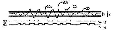
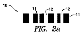
バーコード10(図1)を走査する処理中に、バーコードリーダ又はスキャナによって得られるアナログの光信号は、通常デジタイザによってデジタル化されて例えば矩形波にされる。そのデジタイザの適切な閾値(ゲートレべル)が、図2〜図5に各種の例が模式的に示されているように、信号をノイズから効果的に分離するように採用される。図2〜図5において、デジタルデータ3と4は、高い方と低い方の閾値2と1にそれぞれ対応している。
During the process of scanning the barcode 10 (FIG. 1), the analog optical signal obtained by the barcode reader or scanner is typically digitized by a digitizer, for example, into a square wave. Appropriate threshold values (gate levels) for the digitizer are employed to effectively separate the signal from noise, as various examples are schematically illustrated in FIGS. 2 to 5, digital data 3 and 4 correspond to the higher and
信号20の分解能が高くノイズがない場合は、高い方と低い方の閾値2と1の両方で、正しいデジタルデータ3,4を生成することができる(図2参照)。信号20の分解能が低くノイズが小さい場合は、例えば20a及び20bのような信号成分をミスしないように、低い方の閾値1が使用される(図3参照)。信号20の分解能が高いがノイズも大きい場合は、ノイズを誤検知しないように、高い方の閾値2が使用される(図4参照)。上記何れの状況の場合でも、適切な閾値を選ぶことによって、信号がノイズから効果的に分離される。
When the resolution of the
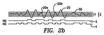
しかしながら、信号20の分解能が低くノイズが大きい場合には、図5に示すように、いくつかの信号成分20a,20bの振幅がノイズ30に近くなり、高い方又は低い方の閾値2又は1のいずれによっても信号がノイズから効果的に分離されない。これは、バーコード10が光ビームの非合焦領域あるいはリーダからの距離が長いところにあるか、バーコードの要素(すなわち、バー11とスペース12)が高密度で印刷されているような状況で起こり得る。
However, when the resolution of the
そのため、デジタル化処理で正しいデジタル出力を生成するように信号からノイズを効果的に除去できるようにする課題を解決する必要がある。 Therefore, there is a need to solve the problem of enabling noise to be effectively removed from a signal so that a correct digital output is generated by a digitization process.
この発明は上記の目的を達成するため、光信号の少なくとも2つのインスタンスを得るために異なる時間に少なくとも2回バーコードを走査する走査工程と、その光信号の上記少なくとも2つのインスタンスをデジタル化して少なくとも2つのデジタルデータにするデジタル化工程と、その少なくとも2つのデジタルデータの両方を用いて出力を生成する出力生成工程とを有するバーコード検知方法を提供する。 To achieve the above object, the present invention digitizes the at least two instances of the optical signal by scanning a bar code at least twice at different times to obtain at least two instances of the optical signal. A barcode detection method is provided that includes a digitizing step for producing at least two digital data, and an output generating step for producing an output using both of the at least two digital data.
なぜならば、ノイズは通常、真のバーコード信号よりランダムな特性で変動するため、異なる時間に得られたオリジナル信号からデジタルデータを生成するために適切なアルゴリズムを適用することによって、ノイズを除去できるからである。上記少なくとも2つのデジタルデータにANDアルゴリズムを適用することによって、その出力が生成されるようにするとよい。 Because noise usually fluctuates with more random characteristics than a true barcode signal, it can be removed by applying an appropriate algorithm to generate digital data from original signals obtained at different times Because. The output may be generated by applying an AND algorithm to the at least two digital data.
上記の方法は、上記少なくとも2つのデジタルデータのタイミングの同期をとる工程を有するのが好ましい。上記異なる時間に得れた光信号の各インスタンスを、少なくとも第1の閾値と第2の閾値でデジタル化するとよい。その第1の閾値によるデジタルデータは出力を生成するために使用され、第2の閾値によるデジタルデータは第1のデジタルデータのタイミングの同期をとるために使用される。通常はノイズは信号より小さいので、上記第2の閾値は第1の閾値より大きい方がよい。 The method preferably includes the step of synchronizing the timing of the at least two digital data. Each instance of the optical signal obtained at the different time may be digitized with at least a first threshold value and a second threshold value. The digital data according to the first threshold is used to generate an output, and the digital data according to the second threshold is used to synchronize the timing of the first digital data. Since the noise is usually smaller than the signal, the second threshold value should be larger than the first threshold value.
この発明はまた、光信号の少なくとも2つのインスタンスを取得するために異なる時間に少なくとも2回バーコードを走査する検出手段と、その光信号の取得した上記少なくとも2つのインスタンスをデジタル化して少なくとも2つのデジタルデータにするデジタル化手段と、その少なくとも2つのデジタルデータの両方を用いて出力を生成する出力生成手段とを有するバーコード検知装置も提供する。
その出力生成手段は、通常ランダムで変動するノイズを除去するために、上記少なくとも2つのデジタルデータにANDアルゴリズムを適用するための手段を有するとよい。
The invention also provides detection means for scanning the barcode at least twice at different times to obtain at least two instances of the optical signal, and digitizing the acquired at least two instances of the optical signal to obtain at least two There is also provided a bar code detection device having digitizing means for converting to digital data and output generating means for generating an output using both of the at least two digital data.
The output generation means may include means for applying an AND algorithm to the at least two digital data in order to remove noise that usually varies randomly.
また、上記少なくとも2つのデジタルデータのタイミングの同期をとる手段を設けるのが望ましい。この装置は、上記光信号のインスタンスから上記デジタルデータを生成するための第1の閾値を持つ第1のデジタイザと、その第1のデジタイザと同時に上記光信号のインスタンスをデジタル化するための第2のデジタイザとを有するとよい。その第2のデジタイザによるデジタルデータは、上記第1のデジタイザによるデジタルデータ間のタイミングの同期をとるために使用される。このように、2つデジタイザあるいは多数のデジタイザの装置によって信号からノイズを効果的に除去して、正しいデジタル出力を得ことができる。 It is desirable to provide means for synchronizing the timing of the at least two digital data. The apparatus includes a first digitizer having a first threshold for generating the digital data from the optical signal instance, and a second digitizer for digitizing the optical signal instance simultaneously with the first digitizer. It is good to have a digitizer. The digital data by the second digitizer is used to synchronize the timing between the digital data by the first digitizer. In this way, noise can be effectively removed from the signal by two digitizers or multiple digitizer devices to obtain the correct digital output.
上記および他の特徴や利点は、以下の添付図面を参照したこの発明の好ましい実施例の詳細な説明によって明らかになるであろう。
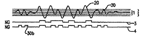
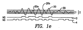
図6〜図9は、信号20におけるいくつかの信号成分20a,20bの振幅がノイズ30のいくつかのレベルと同じになる点で図10と同様な例を示し、各信号とノイズとを効果的に分離できるような適切な閾値を見出せない。信号成分20a,20bの小さい振幅は、その信号成分20a,20bに対応する位置にあるバーコードの要素11,12が高い密度を持つことによって生ずる(図6、図7参照)。
The above and other features and advantages will become apparent from the following detailed description of preferred embodiments of the invention with reference to the accompanying drawings.
6 to 9 show examples similar to those in FIG. 10 in that the amplitudes of some
この発明の教示によれば、光信号20のいくつかのインスタンスは、例えばスキャナ(図示しない)で異なる時間に同じ各インスタンスからの全てのデジタルデータは、ノイズが除去された正しい出力5を生成するために使用される。
図7〜図9は、得られた光信号の3つのインスタンスを例示している。それは高い方の閾値2も低い方の閾値1も、正しいデジタルデータを生成するためにノイズ30を効果的に除去することができないことを明確に示している。さらに、図7〜図9におけるどのデジタルデータ3,4も正しくない。
In accordance with the teachings of the present invention, several instances of the
7-9 illustrate three instances of the resulting optical signal. It clearly shows that neither the
この発明の教示によれば、光信号20の3つのインスタンスそれぞれから第1の閾値で生成されるデジタルデータ4の全てが、最終的な出力5を生成するために使用される。特に、図7〜図9における3つのデジタルデータ4の全てにANDアルゴリズムが適用され、それによって図10に示すように最終出力5が生成される。ノイズ30は通常、信号20よりもランダムな性質があり変動するという事実により、異なる時間に得られた光信号の3つのインスタンスから生成されたデジタルデータ4にANDアルゴリズムを適用することによって、ノイズ30によって生じる不正な波形要素(例えば、要素30aおよび30b)を効果的に除去して、信号20の正しい最終的な出力を生成する。
In accordance with the teachings of the present invention, all of the digital data 4 generated at each of the three instances of the
第1の閾値1は、信号20における振幅が小さい信号成分20a,20bを含む全ての要素を反映できるように適切に選択すべきである。
3つのデジタルデータ4にANDアルゴリズムを適用することによって、3つのデジタルデータ4のタイミングが同期される。信号20は、通常はノイズ30より変動が少ないことに注目する。そのため、第2の閾値2によるデジタルデータ3を、対応するデジタルデータ4におけるタイミングを決定するために使用するとよい。信号の各インスタンスのために、第1および第2の閾値でのデジタル化を同時に実行するとよい。
The
By applying an AND algorithm to the three digital data 4, the timings of the three digital data 4 are synchronized. Note that
第2の閾値2は、比較的安定した信号20を反映させるように適切に選ぶ。信号20は一般にノイズ30より大きいので、第2の閾値2は第1の閾値1より大きいとよく、それによって信号20の成分のみを反映する。しかし、振幅が小さい信号成分20a,20bはノイズ30の振幅に近いため、第2の閾値2によっては多分反映されないことに注意する。
The
好ましい実施例において、2つのデジタイザを持つ装置がデジタル化処理を実行するために使用される。特に、光信号の各インスタンスが、第1の低い方の閾値1を持つ第1のデジタイザと第2の高い方のデジタイザに、それぞれデジタルデータ4と3を生成するために入力される。好ましくは、2つのデジタイザが光信号の各インスタンスをタイミングの決定と同期のために同時にデジタル化する。
In the preferred embodiment, a device with two digitizers is used to perform the digitization process. In particular, each instance of the optical signal is input to a first digitizer having a first
図11および図12は、この発明による2つのデジタイザを持つ装置の2つの実施例を示す。図11の実施例においては、2つのデジタイザ41,42がその装置のデジタルモジュールに含まれており、一方、図12の実施例においては、2つのデジタイザ41,42がその装置のアナログモジュールの部分に含まれている。そのデジタイザ41,42の閾値はCPU43によるゲートレベル制御信号によって制御される。信号の各インスタンスのデジタルデータ3,4は、デジタイザ41,42からデジタルデータ間のタイミングの同期および正しいデジタル出力を生成するためのデジタルデータ4への適切なアルゴリズム(例えば、ANDアルゴリズム)の適用を含む処理のために、メモリであるRAM44に与えられる。
FIGS. 11 and 12 show two embodiments of a device having two digitizers according to the present invention. In the embodiment of FIG. 11, two
図13は、図11および図12示したような装置によって実行されるこの発明による方法の各工程を示す。
ブロック(工程)100で、光信号のインスタンスを得るためにバーコードが一度走査され、その光信号はステップ(工程)110において、図11および図12に示されたプリアンプ、微分回路、AGC(自動ゲイン制御アンプ)、LPF(ローパスフィルタ)、ADC(アナログ・デジタル変換器)のうちの一つ以上によって前処理される。その前処理された信号は、それからステップ120で、第1の閾値を持つ第1のデジタイザ41と第2の閾値を持つ第2のデジタイザ42の両方に入力される。ステップ130では、異なる閾値を持つ2つのデジタイザ41,42によって2つの異なるデジタルデータが生成される。
FIG. 13 shows the steps of the method according to the invention which are carried out by the apparatus as shown in FIGS.
In block (process) 100, the bar code is scanned once to obtain an instance of the optical signal, and in step (process) 110, the optical signal is scanned by the preamplifier, differentiation circuit, AGC (automatic circuit) shown in FIGS. It is preprocessed by one or more of a gain control amplifier, LPF (low pass filter), and ADC (analog / digital converter). The preprocessed signal is then input at
140のブロックでは、第2の閾値を持つ第2のデジタイザ42によって生成されたデジタルデータが、第1の閾値を持つ第1のデジタイザ41によって生成されたデジタルデータのタイミングを決定するために使用される。もしブロック150で、さらにインスタンスが必要と判断されると、次のインスタンスを得るために、処理がクロック100に戻る。もし信号の更なるインスタンスが要らないと判断された場合は、ブロック100で得られた信号の全てのインスタンスから第1の閾値を持つ第1のデジタイザ41によって生成されたデジタルデータが、ブロック160でタイミングの同期を取られANDアルゴリズムが適用され、それによって、ブロック170で最終的に正しいデジタル出力信号が生成される。
In
上述したこの発明好ましい実施例は、種々の適用、修正及び変更が当業者にはこの発明の要旨をはずれることなく可能であることが分かる。例えば、上記デジタルデータに対するANDアルゴリズムの適用に代えて、他の適切なアルゴリズムを使用することができる。例えば、もし全てのデータをストアするためのメモリスペースが充分あれば、ANDアルゴリズムよりむしろ確率アルゴリズムを適用するとよい。 It will be understood by those skilled in the art that the above-described preferred embodiments of the present invention can be variously applied, modified and changed without departing from the spirit of the present invention. For example, instead of applying the AND algorithm to the digital data, other suitable algorithms can be used. For example, if there is enough memory space to store all the data, a probability algorithm may be applied rather than an AND algorithm.
図6〜図10に示した実施例では光信号の3つのインスタンスを使用したが、代わりに2つあるいは3つ以上のインスタンスを使用してもよい。さらに、精度を増すために2つ以上の閾値を使用してもよい。
また、矩形波を生成する閾値を使用する代わりに他のタイプのデジタル化方法を用いてもよい。そもため、この発明の範囲は、特許請求の範囲によって規定されるだけである。
Although the embodiments shown in FIGS. 6-10 used three instances of an optical signal, two or more instances may be used instead. In addition, more than one threshold may be used to increase accuracy.
Further, instead of using a threshold value for generating a rectangular wave, another type of digitization method may be used. Therefore, the scope of the present invention is only defined by the claims.
Claims (31)
前記光信号の前記少なくとも2つのインスタンスをデジタル化して少なくとも2つのデジタルデータにするデジタル化工程と、
その少なくとも2つのデジタルデータの両方を用いて出力を生成する出力生成工程と、
を有するバーコード検知方法。 A scanning step of scanning the barcode at least twice at different times to obtain at least two instances of the optical signal;
Digitizing the at least two instances of the optical signal into at least two digital data;
An output generating step for generating an output using both of the at least two digital data;
A barcode detection method comprising:
前記光信号の取得した前記少なくとも2つのインスタンスをデジタル化して少なくとも2つのデジタルデータにするデジタル化手段と、
前記少なくとも2つのデジタルデータの両方を用いて出力を生成する出力生成手段と、
を有するバーコード検知装置。 Detecting means for scanning the barcode at least twice at different times to obtain at least two instances of the optical signal;
Digitizing means for digitizing the acquired at least two instances of the optical signal into at least two digital data;
Output generating means for generating an output using both of the at least two digital data;
A bar code detecting device.
各タイミングで得られた前記光信号を第2の閾値で第2のデジタルデータのインスタンスにデジタル化する第2のデジタイザと、
前記第2のデジタルデータを使用して前記第1のデジタルデータのタイミングを決定する手段と、
を有する安定した信号源から得られた光信号をデジタル化するためのデジタル化装置。 A first digitizer for digitizing each instance of an optical signal obtained from a signal source into first digital data with a first threshold;
A second digitizer that digitizes the optical signal obtained at each timing into a second digital data instance with a second threshold;
Means for determining the timing of the first digital data using the second digital data;
A digitizing device for digitizing an optical signal obtained from a stable signal source.
Applications Claiming Priority (2)
| Application Number | Priority Date | Filing Date | Title |
|---|---|---|---|
| US11/125,399 US7354000B2 (en) | 2005-05-05 | 2005-05-05 | Method and system for sensing a barcode |
| PCT/US2006/017002 WO2006121730A1 (en) | 2005-05-05 | 2006-05-03 | Method and system for sensing a barcode |
Publications (2)
| Publication Number | Publication Date |
|---|---|
| JP2008541236A true JP2008541236A (en) | 2008-11-20 |
| JP2008541236A5 JP2008541236A5 (en) | 2012-02-16 |
Family
ID=37393204
Family Applications (1)
| Application Number | Title | Priority Date | Filing Date |
|---|---|---|---|
| JP2008510172A Pending JP2008541236A (en) | 2005-05-05 | 2006-05-03 | Barcode detection method and apparatus |
Country Status (5)
| Country | Link |
|---|---|
| US (1) | US7354000B2 (en) |
| JP (1) | JP2008541236A (en) |
| DE (1) | DE112006001171T5 (en) |
| GB (1) | GB2440080B (en) |
| WO (1) | WO2006121730A1 (en) |
Families Citing this family (3)
| Publication number | Priority date | Publication date | Assignee | Title |
|---|---|---|---|---|
| US9038917B2 (en) | 2012-02-01 | 2015-05-26 | Optoelectronics Co. Ltd. | System and method for noise reduction in a bar code signal |
| EP2834772A4 (en) | 2012-04-03 | 2015-12-16 | Optoelectronics Co Ltd | Variable gain amplifier for bar code reader |
| CN108171118B (en) * | 2017-12-05 | 2020-10-02 | 东软集团股份有限公司 | Blink signal data processing method and device, readable storage medium and electronic equipment |
Citations (13)
| Publication number | Priority date | Publication date | Assignee | Title |
|---|---|---|---|---|
| JPS53122327A (en) * | 1977-03-31 | 1978-10-25 | Omron Tateisi Electronics Co | Bar code reader |
| JPS53129534A (en) * | 1977-04-18 | 1978-11-11 | Hokushin Electric Works | Read signal discriminator for bar code reader |
| JPS5461420A (en) * | 1977-10-25 | 1979-05-17 | Fujitsu Ltd | Data input system |
| JPS6126185A (en) * | 1984-07-16 | 1986-02-05 | Ricoh Co Ltd | Bar code scanning system |
| JPS6235986A (en) * | 1985-08-10 | 1987-02-16 | Fujitsu Ltd | Bar code reader |
| JPS63150777A (en) * | 1986-12-08 | 1988-06-23 | インターナシヨナル・ビジネス・マシーンズ・コーポレーシヨン | Sampling speed varying holograph scanner |
| JPH056455A (en) * | 1991-06-27 | 1993-01-14 | Ricoh Res Inst Of Gen Electron | Pulse noise eliminating circuit |
| JPH0589278A (en) * | 1991-09-25 | 1993-04-09 | Olympus Optical Co Ltd | Bar code symbol reader |
| JPH05298471A (en) * | 1992-04-20 | 1993-11-12 | Fujitsu Ltd | Bar code reader |
| JPH07105304A (en) * | 1992-07-13 | 1995-04-21 | Olympus Optical Co Ltd | Bar code scanning and link method |
| JPH07200712A (en) * | 1993-12-13 | 1995-08-04 | At & T Global Inf Solutions Internatl Inc | Method and apparatus for readout of bar code |
| US6082621A (en) * | 1992-04-02 | 2000-07-04 | Symbol Technologies, Inc. | Interface between threshold processing digitizer for bar code reader |
| US20020162890A1 (en) * | 1991-07-25 | 2002-11-07 | Symbol Technologies, Inc., A Delaware Corporation | Multi-channel signal processing in an optical reader |
Family Cites Families (28)
| Publication number | Priority date | Publication date | Assignee | Title |
|---|---|---|---|---|
| JPS6065383A (en) | 1983-09-20 | 1985-04-15 | Fujitsu Ltd | Bar code reader |
| JPS6441079U (en) | 1987-08-28 | 1989-03-10 | ||
| JPH0325585A (en) | 1989-06-22 | 1991-02-04 | Hitachi Electron Eng Co Ltd | Erroneous reading prevention device in bar code reader |
| KR950013780B1 (en) * | 1990-05-22 | 1995-11-16 | 후루까와 뗀끼 고요교오 가부시끼가이샤 | Apparatus and method for measuring length of moving elongated object |
| JPH04181384A (en) | 1990-11-15 | 1992-06-29 | Sumitomo Electric Ind Ltd | Symbol reader |
| CA2032941C (en) * | 1990-08-21 | 1996-01-16 | Masashi Nishida | Identification mark reading apparatus |
| US5278397A (en) * | 1991-07-25 | 1994-01-11 | Symbol Technologies, Inc. | Multi-resolution bar code reader |
| US5371361A (en) * | 1993-02-01 | 1994-12-06 | Spectra-Physics Scanning Systems, Inc. | Optical processing system |
| US6527180B1 (en) | 1993-11-17 | 2003-03-04 | Symbol Technologies, Inc. | Compact dual optical and scan modules in bar code readers |
| US5767501A (en) * | 1993-11-24 | 1998-06-16 | Metrologic Instruments, Inc. | Mass-balanced automatic hand-supportable laser projection scanner for fatigue-free omnidirectional scanning of bar code symbols |
| JP2713126B2 (en) | 1993-12-20 | 1998-02-16 | 日本電気株式会社 | Optical receiver |
| US5457309A (en) * | 1994-03-18 | 1995-10-10 | Hand Held Products | Predictive bar code decoding system and method |
| US6708883B2 (en) * | 1994-06-30 | 2004-03-23 | Symbol Technologies, Inc. | Apparatus and method for reading indicia using charge coupled device and scanning laser beam technology |
| US6343741B1 (en) * | 1995-10-26 | 2002-02-05 | Psc Scanning, Inc. | Method and apparatus for detecting transitions in an input signal |
| US6729543B1 (en) * | 1998-03-06 | 2004-05-04 | Audiovelocity, Inc. | Page identification system and method |
| US6616043B2 (en) * | 1998-04-07 | 2003-09-09 | Victor Zazzu | Multi sensor information reader |
| JPH11316794A (en) | 1998-05-06 | 1999-11-16 | Aisin Aw Seimitsu Kk | Method for reading and deciding segment information |
| JP2000151290A (en) | 1998-11-05 | 2000-05-30 | Nec Corp | Initial-stage amplifying circuit |
| US6830190B2 (en) * | 1999-02-02 | 2004-12-14 | Metrologic Instruments, Inc. | Multipath scan data signal processor having multiple signal processing paths with different operational characteristics to enable processing of signals having increased dynamic range |
| JP3881809B2 (en) | 1999-06-10 | 2007-02-14 | Necインフロンティア株式会社 | Signal waveform processing circuit provided with AGC circuit |
| ATE453899T1 (en) * | 1999-10-26 | 2010-01-15 | Datalogic Spa | METHOD FOR RECONSTRUCTING A STRIP CODE BY SEQUENTIAL SCANNING |
| JP3456574B2 (en) | 1999-11-10 | 2003-10-14 | 日本電気株式会社 | Burst mode optical receiving system and method |
| JP2001196877A (en) | 2000-01-06 | 2001-07-19 | Mitsubishi Electric Corp | Preamplifier circuit |
| EP1205871B1 (en) * | 2000-11-10 | 2006-08-23 | Datalogic S.P.A. | Device for reading coded information |
| US6729603B1 (en) * | 2001-06-08 | 2004-05-04 | Psc Scanning, Inc. | Add-on capture rate in a barcode scanning system |
| JP2003030577A (en) | 2001-07-16 | 2003-01-31 | Toshiba Tec Corp | Bar code reader |
| JP2003337941A (en) | 2002-05-20 | 2003-11-28 | Matsushita Electric Ind Co Ltd | Device and method for image recognition, and program |
| US6827266B2 (en) * | 2002-10-04 | 2004-12-07 | Ncr Corporation | Methods and apparatus for using imaging information to improve scanning accuracy in bar code scanners |
-
2005
- 2005-05-05 US US11/125,399 patent/US7354000B2/en not_active Expired - Fee Related
-
2006
- 2006-05-03 WO PCT/US2006/017002 patent/WO2006121730A1/en active Search and Examination
- 2006-05-03 GB GB0721593A patent/GB2440080B/en not_active Expired - Fee Related
- 2006-05-03 DE DE112006001171T patent/DE112006001171T5/en not_active Withdrawn
- 2006-05-03 JP JP2008510172A patent/JP2008541236A/en active Pending
Patent Citations (13)
| Publication number | Priority date | Publication date | Assignee | Title |
|---|---|---|---|---|
| JPS53122327A (en) * | 1977-03-31 | 1978-10-25 | Omron Tateisi Electronics Co | Bar code reader |
| JPS53129534A (en) * | 1977-04-18 | 1978-11-11 | Hokushin Electric Works | Read signal discriminator for bar code reader |
| JPS5461420A (en) * | 1977-10-25 | 1979-05-17 | Fujitsu Ltd | Data input system |
| JPS6126185A (en) * | 1984-07-16 | 1986-02-05 | Ricoh Co Ltd | Bar code scanning system |
| JPS6235986A (en) * | 1985-08-10 | 1987-02-16 | Fujitsu Ltd | Bar code reader |
| JPS63150777A (en) * | 1986-12-08 | 1988-06-23 | インターナシヨナル・ビジネス・マシーンズ・コーポレーシヨン | Sampling speed varying holograph scanner |
| JPH056455A (en) * | 1991-06-27 | 1993-01-14 | Ricoh Res Inst Of Gen Electron | Pulse noise eliminating circuit |
| US20020162890A1 (en) * | 1991-07-25 | 2002-11-07 | Symbol Technologies, Inc., A Delaware Corporation | Multi-channel signal processing in an optical reader |
| JPH0589278A (en) * | 1991-09-25 | 1993-04-09 | Olympus Optical Co Ltd | Bar code symbol reader |
| US6082621A (en) * | 1992-04-02 | 2000-07-04 | Symbol Technologies, Inc. | Interface between threshold processing digitizer for bar code reader |
| JPH05298471A (en) * | 1992-04-20 | 1993-11-12 | Fujitsu Ltd | Bar code reader |
| JPH07105304A (en) * | 1992-07-13 | 1995-04-21 | Olympus Optical Co Ltd | Bar code scanning and link method |
| JPH07200712A (en) * | 1993-12-13 | 1995-08-04 | At & T Global Inf Solutions Internatl Inc | Method and apparatus for readout of bar code |
Also Published As
| Publication number | Publication date |
|---|---|
| DE112006001171T5 (en) | 2008-04-10 |
| GB0721593D0 (en) | 2007-12-12 |
| US20060249583A1 (en) | 2006-11-09 |
| US7354000B2 (en) | 2008-04-08 |
| GB2440080B (en) | 2011-05-04 |
| GB2440080A (en) | 2008-01-16 |
| WO2006121730A1 (en) | 2006-11-16 |
Similar Documents
| Publication | Publication Date | Title |
|---|---|---|
| US5286960A (en) | Method of programmable digitization and bar code scanning apparatus employing same | |
| JPH032990A (en) | Analog signal processing system for bar code reader | |
| US4222077A (en) | Analog-digital conversion method, and a picture reproduction method using the same | |
| JP2008541236A (en) | Barcode detection method and apparatus | |
| JPH1090059A (en) | Method for correcting focal plane array | |
| JP2008541236A5 (en) | ||
| JP2010078364A (en) | Radar apparatus | |
| US20200088856A1 (en) | Signal processing apparatus, distance measuring apparatus, and distance measuring method | |
| JP2004340784A (en) | Star sensor | |
| US6549573B2 (en) | Testing method and apparatus of glitch noise and storage medium | |
| JP2010182262A (en) | Information reading apparatus | |
| JP5219943B2 (en) | Binarization method and binarization circuit | |
| JP2006343252A (en) | Signal detection method and signal detection device | |
| JP5441200B1 (en) | Bar code reading apparatus and bar code reading method | |
| JPS62219754A (en) | Picture reader | |
| JPH0757080A (en) | Adaptive binarization control system | |
| JP4013695B2 (en) | Image processing method and image processing apparatus | |
| JPH0737019A (en) | Optical reader | |
| JPH08334683A (en) | Automatic in-focus device | |
| JPH0642199Y2 (en) | Defect discrimination circuit | |
| JP3392934B2 (en) | Data symbol reading device | |
| JPH0325690A (en) | Signal processing method for bar code reader | |
| JP2011095305A (en) | Sound recording device, imaging device and program | |
| JP2615928B2 (en) | Data reader | |
| JPH0618442A (en) | Inspection device |
Legal Events
| Date | Code | Title | Description |
|---|---|---|---|
| A521 | Written amendment |
Free format text: JAPANESE INTERMEDIATE CODE: A523 Effective date: 20090507 |
|
| A621 | Written request for application examination |
Free format text: JAPANESE INTERMEDIATE CODE: A621 Effective date: 20090507 |
|
| A524 | Written submission of copy of amendment under section 19 (pct) |
Free format text: JAPANESE INTERMEDIATE CODE: A524 Effective date: 20111209 |
|
| A521 | Written amendment |
Free format text: JAPANESE INTERMEDIATE CODE: A523 Effective date: 20111213 |
|
| A131 | Notification of reasons for refusal |
Free format text: JAPANESE INTERMEDIATE CODE: A131 Effective date: 20120228 |
|
| A02 | Decision of refusal |
Free format text: JAPANESE INTERMEDIATE CODE: A02 Effective date: 20120717 |