JP2008540918A - Structural tower - Google Patents
Structural tower Download PDFInfo
- Publication number
- JP2008540918A JP2008540918A JP2008511391A JP2008511391A JP2008540918A JP 2008540918 A JP2008540918 A JP 2008540918A JP 2008511391 A JP2008511391 A JP 2008511391A JP 2008511391 A JP2008511391 A JP 2008511391A JP 2008540918 A JP2008540918 A JP 2008540918A
- Authority
- JP
- Japan
- Prior art keywords
- members
- longitudinal
- diagonal
- structural tower
- longitudinal members
- Prior art date
- Legal status (The legal status is an assumption and is not a legal conclusion. Google has not performed a legal analysis and makes no representation as to the accuracy of the status listed.)
- Pending
Links
Images


Classifications
-
- E—FIXED CONSTRUCTIONS
- E04—BUILDING
- E04H—BUILDINGS OR LIKE STRUCTURES FOR PARTICULAR PURPOSES; SWIMMING OR SPLASH BATHS OR POOLS; MASTS; FENCING; TENTS OR CANOPIES, IN GENERAL
- E04H12/00—Towers; Masts or poles; Chimney stacks; Water-towers; Methods of erecting such structures
- E04H12/02—Structures made of specified materials
- E04H12/08—Structures made of specified materials of metal
- E04H12/10—Truss-like structures
-
- E—FIXED CONSTRUCTIONS
- E02—HYDRAULIC ENGINEERING; FOUNDATIONS; SOIL SHIFTING
- E02B—HYDRAULIC ENGINEERING
- E02B17/00—Artificial islands mounted on piles or like supports, e.g. platforms on raisable legs or offshore constructions; Construction methods therefor
- E02B17/0004—Nodal points
-
- E—FIXED CONSTRUCTIONS
- E02—HYDRAULIC ENGINEERING; FOUNDATIONS; SOIL SHIFTING
- E02B—HYDRAULIC ENGINEERING
- E02B17/00—Artificial islands mounted on piles or like supports, e.g. platforms on raisable legs or offshore constructions; Construction methods therefor
- E02B17/02—Artificial islands mounted on piles or like supports, e.g. platforms on raisable legs or offshore constructions; Construction methods therefor placed by lowering the supporting construction to the bottom, e.g. with subsequent fixing thereto
- E02B17/027—Artificial islands mounted on piles or like supports, e.g. platforms on raisable legs or offshore constructions; Construction methods therefor placed by lowering the supporting construction to the bottom, e.g. with subsequent fixing thereto steel structures
-
- F—MECHANICAL ENGINEERING; LIGHTING; HEATING; WEAPONS; BLASTING
- F03—MACHINES OR ENGINES FOR LIQUIDS; WIND, SPRING, OR WEIGHT MOTORS; PRODUCING MECHANICAL POWER OR A REACTIVE PROPULSIVE THRUST, NOT OTHERWISE PROVIDED FOR
- F03D—WIND MOTORS
- F03D13/00—Assembly, mounting or commissioning of wind motors; Arrangements specially adapted for transporting wind motor components
- F03D13/10—Assembly of wind motors; Arrangements for erecting wind motors
-
- F—MECHANICAL ENGINEERING; LIGHTING; HEATING; WEAPONS; BLASTING
- F03—MACHINES OR ENGINES FOR LIQUIDS; WIND, SPRING, OR WEIGHT MOTORS; PRODUCING MECHANICAL POWER OR A REACTIVE PROPULSIVE THRUST, NOT OTHERWISE PROVIDED FOR
- F03D—WIND MOTORS
- F03D13/00—Assembly, mounting or commissioning of wind motors; Arrangements specially adapted for transporting wind motor components
- F03D13/20—Arrangements for mounting or supporting wind motors; Masts or towers for wind motors
-
- E—FIXED CONSTRUCTIONS
- E02—HYDRAULIC ENGINEERING; FOUNDATIONS; SOIL SHIFTING
- E02B—HYDRAULIC ENGINEERING
- E02B17/00—Artificial islands mounted on piles or like supports, e.g. platforms on raisable legs or offshore constructions; Construction methods therefor
- E02B2017/0056—Platforms with supporting legs
- E02B2017/006—Platforms with supporting legs with lattice style supporting legs
-
- E—FIXED CONSTRUCTIONS
- E02—HYDRAULIC ENGINEERING; FOUNDATIONS; SOIL SHIFTING
- E02B—HYDRAULIC ENGINEERING
- E02B17/00—Artificial islands mounted on piles or like supports, e.g. platforms on raisable legs or offshore constructions; Construction methods therefor
- E02B2017/0091—Offshore structures for wind turbines
-
- F—MECHANICAL ENGINEERING; LIGHTING; HEATING; WEAPONS; BLASTING
- F05—INDEXING SCHEMES RELATING TO ENGINES OR PUMPS IN VARIOUS SUBCLASSES OF CLASSES F01-F04
- F05B—INDEXING SCHEME RELATING TO WIND, SPRING, WEIGHT, INERTIA OR LIKE MOTORS, TO MACHINES OR ENGINES FOR LIQUIDS COVERED BY SUBCLASSES F03B, F03D AND F03G
- F05B2230/00—Manufacture
- F05B2230/20—Manufacture essentially without removing material
- F05B2230/23—Manufacture essentially without removing material by permanently joining parts together
- F05B2230/232—Manufacture essentially without removing material by permanently joining parts together by welding
-
- F—MECHANICAL ENGINEERING; LIGHTING; HEATING; WEAPONS; BLASTING
- F05—INDEXING SCHEMES RELATING TO ENGINES OR PUMPS IN VARIOUS SUBCLASSES OF CLASSES F01-F04
- F05B—INDEXING SCHEME RELATING TO WIND, SPRING, WEIGHT, INERTIA OR LIKE MOTORS, TO MACHINES OR ENGINES FOR LIQUIDS COVERED BY SUBCLASSES F03B, F03D AND F03G
- F05B2240/00—Components
- F05B2240/90—Mounting on supporting structures or systems
- F05B2240/91—Mounting on supporting structures or systems on a stationary structure
- F05B2240/912—Mounting on supporting structures or systems on a stationary structure on a tower
- F05B2240/9121—Mounting on supporting structures or systems on a stationary structure on a tower on a lattice tower
-
- F—MECHANICAL ENGINEERING; LIGHTING; HEATING; WEAPONS; BLASTING
- F05—INDEXING SCHEMES RELATING TO ENGINES OR PUMPS IN VARIOUS SUBCLASSES OF CLASSES F01-F04
- F05B—INDEXING SCHEME RELATING TO WIND, SPRING, WEIGHT, INERTIA OR LIKE MOTORS, TO MACHINES OR ENGINES FOR LIQUIDS COVERED BY SUBCLASSES F03B, F03D AND F03G
- F05B2260/00—Function
- F05B2260/30—Retaining components in desired mutual position
- F05B2260/301—Retaining bolts or nuts
-
- Y—GENERAL TAGGING OF NEW TECHNOLOGICAL DEVELOPMENTS; GENERAL TAGGING OF CROSS-SECTIONAL TECHNOLOGIES SPANNING OVER SEVERAL SECTIONS OF THE IPC; TECHNICAL SUBJECTS COVERED BY FORMER USPC CROSS-REFERENCE ART COLLECTIONS [XRACs] AND DIGESTS
- Y02—TECHNOLOGIES OR APPLICATIONS FOR MITIGATION OR ADAPTATION AGAINST CLIMATE CHANGE
- Y02E—REDUCTION OF GREENHOUSE GAS [GHG] EMISSIONS, RELATED TO ENERGY GENERATION, TRANSMISSION OR DISTRIBUTION
- Y02E10/00—Energy generation through renewable energy sources
- Y02E10/70—Wind energy
- Y02E10/72—Wind turbines with rotation axis in wind direction
-
- Y—GENERAL TAGGING OF NEW TECHNOLOGICAL DEVELOPMENTS; GENERAL TAGGING OF CROSS-SECTIONAL TECHNOLOGIES SPANNING OVER SEVERAL SECTIONS OF THE IPC; TECHNICAL SUBJECTS COVERED BY FORMER USPC CROSS-REFERENCE ART COLLECTIONS [XRACs] AND DIGESTS
- Y02—TECHNOLOGIES OR APPLICATIONS FOR MITIGATION OR ADAPTATION AGAINST CLIMATE CHANGE
- Y02E—REDUCTION OF GREENHOUSE GAS [GHG] EMISSIONS, RELATED TO ENERGY GENERATION, TRANSMISSION OR DISTRIBUTION
- Y02E10/00—Energy generation through renewable energy sources
- Y02E10/70—Wind energy
- Y02E10/728—Onshore wind turbines
-
- Y—GENERAL TAGGING OF NEW TECHNOLOGICAL DEVELOPMENTS; GENERAL TAGGING OF CROSS-SECTIONAL TECHNOLOGIES SPANNING OVER SEVERAL SECTIONS OF THE IPC; TECHNICAL SUBJECTS COVERED BY FORMER USPC CROSS-REFERENCE ART COLLECTIONS [XRACs] AND DIGESTS
- Y02—TECHNOLOGIES OR APPLICATIONS FOR MITIGATION OR ADAPTATION AGAINST CLIMATE CHANGE
- Y02P—CLIMATE CHANGE MITIGATION TECHNOLOGIES IN THE PRODUCTION OR PROCESSING OF GOODS
- Y02P70/00—Climate change mitigation technologies in the production process for final industrial or consumer products
- Y02P70/50—Manufacturing or production processes characterised by the final manufactured product
Abstract
風力タービンに向けた特定の用途で、高度が高く、荷重が重い用途のためのスペースフレーム構成を有する構造タワーが開示されている。構造タワーは、スペースフレームの長手方向、対角線または水平方向部材内の減衰または非減衰支柱を含む。構造タワー内の1つまたは複数の減衰支柱は、非周期的な突風または持続する高速の風によって生じる共鳴振動または振動を減衰させる。構造タワーの種々の長手方向および対角線部材は、スペースフレームの対応する長手方向または対角線継手にピン、ボルト、フランジまたは溶接によって固定することができる。
【選択図】なしA structural tower is disclosed having a space frame configuration for high altitude and heavy load applications in specific applications for wind turbines. The structural tower includes damped or non-damped struts in the longitudinal, diagonal or horizontal members of the space frame. One or more damping struts in the structural tower dampen resonant vibrations or vibrations caused by non-periodic gusts or sustained high speed winds. The various longitudinal and diagonal members of the structural tower can be secured to the corresponding longitudinal or diagonal joint of the space frame by pins, bolts, flanges or welding.
[Selection figure] None
Description
本発明は、「構造タワー」の名称で2005年5月13日に出願された、米国仮特許出願第60/681、235号の優先権を主張する。 The present invention claims the priority of US Provisional Patent Application No. 60 / 681,235, filed May 13, 2005 under the name “Structural Tower”.
本発明は、構造タワー、および風力タービン用の構造タワーに関する特定の用途で構造タワーの振動を減衰する装置に関する。 The present invention relates to structural towers and devices for dampening structural tower vibrations in particular applications relating to structural towers for wind turbines.
風力タービンは、米国、欧州および世界中の他の多くの国で、益々一般的になっているエネルギー源である。風からエネルギーを捕らえるスケール効果を実現するために、開発者等は、より大きな高さで配置されるより大型のタービンを備え、数が増大する風力タービンを有する風力タービンファームを建設している。大型の風力タービンファーム事業において、例えば開発者等は通常、50メータ以上で配置されるほぼ1.2MWのタービンを有する25基以上の風力タービンを使用する。これらの数は、エネルギーコストを減少させ、開発者にとって事業を有利にさせるスケール効果を実現する。より高い高さの大型のタービンを配置することにより、ウィンドシアーによって生じる境界層の影響、および例えば岩や木など地面に近い表面形状の不規則性の干渉の影響をほぼ受けずに各タービンが作動することが可能になる。またタービンの高さを大きくすることは、より高速で持続する風速でのより安定した作動状態につながり、これにより平均して時間単位につきより大きなエネルギーが生成される。したがって、より大きな高さで大型のタービンを配置することは、経済的で技術的な誘因である。 Wind turbines are an increasingly popular energy source in the United States, Europe and many other countries around the world. In order to achieve a scale effect that captures energy from the wind, developers and others are building wind turbine farms with larger number of wind turbines with larger turbines arranged at higher heights. In a large wind turbine farm business, for example, developers typically use more than 25 wind turbines with approximately 1.2 MW turbines arranged at 50 meters or more. These numbers provide a scale effect that reduces energy costs and makes the business more advantageous to developers. By placing a larger turbine at a higher height, each turbine is almost unaffected by the boundary layer effects caused by wind shear and the interference of surface irregularities such as rocks and wood. It becomes possible to operate. Increasing the height of the turbine also leads to a more stable operating condition at higher and sustained wind speeds, which on average produces more energy per time unit. Thus, placing a large turbine at a greater height is an economic and technical incentive.
しかしながら、より大きな高さでの大型のタービンの配置には費用の問題がある。費用は、より大型でより大規模のタワーは大型のタービンの追加的重量に耐え、風速もより大きくなり、さらに持続するより大きな高さに構造物を配置することによって生じる風荷重に耐える必要があることと関連している。追加の費用は、風力タービンを建設するのに必要とされる装置に関係する。例えば、鋼鉄またはコンクリートを使用して構築された構造物などの区分化された管を有するタワーなど風力タービン用の従来の管タワーの重量は、5/3出力まで引き上げられたタワーの高度に比例して増加する。したがって通常、標準65メータの高さで176,000ポンドの重量の1.5 MWのタワーは、85メータの高さでおよそ275、000ポンドであり、増加率は約56パーセントである。しかしながら、250、000ポンドを超える、または100メータより高いタワーは、一般にタワー部とタービンを組み立てるのに特化された高価なクレーンを必要とする。単にこれらのクレーンの1つを輸送し組み立てるコストは、典型的な1.5MWのタービンに対して250、000ドルを超えることがある。このような大型クレーンに関する費用を償却するために、風力タービンファームの開発者等は、事業の設置面積に可能な限り多くの風力タービンを詰め込むことを望むため、多くの風力タービンに関するクレーンコストが拡大する。しかしながら設置面積が限定された用地では、開発者等は、より少ないタービンを使用してクレーンの輸送および組立コストを償却することを強いられ、これは経済的にも不可能な場合がある。さらに起伏のある地面に設置される事業は、クレーンを繰り返し組立ておよび分解することが要求され、やはり経済的に不可能な場合がある。山の頂上尾根または他の運搬上困難な用地に位置する事業は、同様に経済的に不可能なこと、さらにこのような用地にクレーンを配置することに関する工学的困難からほとんど排除されうる。 大型でより大規模なタワーに関して他にも問題がある。例えば、タービンの高さが約90メータを超える場合、従来の管タワーの管の直径は、道路の高さおよび重量制限を超える場合がある。風力タービン産業は、タワーの部品を長手方向に分割し積み出し、用地で部品を再度組み立てることを研究してきた。しかしながら、追加の組立コストがこの代替案を魅力のないものにしている。管の直径がより高いタワーに使用されるものより小さい80メータでさえ、ほとんどの最上部のタワー区分は、各州間の道路の受容力80、000ポンドを超える。特大のトレーラ、およびタワー部分の特殊な通過に関する運搬コストは、風力タービンにつき何万ドルも超過する場合がある。したがって、大型の鋼鉄管タワーの輸送コストは、そうでなければ風力タービン用に実用的な用地の開発を排除または妨害することがある。 However, the placement of large turbines at higher heights is a cost issue. The cost is that larger and larger towers need to withstand the additional weight of large turbines, wind speeds and even the wind loads caused by placing structures at a sustained and higher height. Related to being. The additional cost is related to the equipment required to build the wind turbine. For example, the weight of conventional tube towers for wind turbines, such as towers with segmented tubes such as structures built using steel or concrete, is proportional to the height of the tower raised to 5/3 power Then increase. Thus, typically a 1.5 MW tower weighing 176,000 pounds at a standard 65 meter height is approximately 275,000 pounds at a height of 85 meters, with an increase of about 56 percent. However, towers over 250,000 pounds or higher than 100 meters generally require expensive cranes specialized to assemble the tower section and turbine. The cost of simply transporting and assembling one of these cranes can exceed $ 250,000 for a typical 1.5 MW turbine. To amortize the costs associated with these large cranes, wind turbine farm developers want to pack as many wind turbines as possible into their business footprint, which increases crane costs for many wind turbines. To do. However, on sites with limited footprint, developers are forced to amortize crane transportation and assembly costs using fewer turbines, which may not be economically feasible. Furthermore, businesses installed on rough ground require repeated assembly and disassembly of the crane, which may still be economically impossible. Projects located on mountaintop ridges or other difficult-to-carry sites can be largely eliminated from what is equally economically impossible and the engineering difficulties associated with placing cranes on such sites. There are other problems with larger and larger towers. For example, if the height of the turbine exceeds about 90 meters, the tube diameter of the conventional tube tower may exceed the road height and weight limits. The wind turbine industry has been studying how to divide the tower parts in the longitudinal direction and load and reassemble the parts on site. However, additional assembly costs make this alternative unattractive. Even the 80 meter, smaller than that used for higher diameter towers, most top tower sections exceed 80,000 pounds of interstate road capacity. Transportation costs associated with oversized trailers and special passages in the tower section can exceed tens of thousands of dollars per wind turbine. Thus, the transportation costs of large steel tube towers may eliminate or impede the development of practical sites for wind turbines otherwise.
従来の管風力タービンタワーは65メータを超える高さであり、70メータを超えるロータ径(または、ブレードロータの長さがほぼ35メータ)を有してよい。増加するタービンの高さと共にさらに大きなロータ径を使用することは、この産業に対するさらなる挑戦を提示する。より大きな高さでのより大きなロータ径は、より低い風速からより大きなエネルギーを捕らえ、単位時間ごとにタービンに輸送することができる点で有益である。しかしながら、より大きな高さでのより大きなロータ径は、より大きな風に誘発される風力タービン構造全体、および詳細には風力タービンを支持するタワー全体の振動につながる傾向がある。風が誘発する振動は、詳細には、タワー内にもたらされる共鳴する横方向のねじり振動であり、タービンの高さが80から100メータに達するまたはこれを超え、ロータ径が70メータを超えると過大になりうる。 Conventional tube wind turbine towers can be over 65 meters high and have a rotor diameter of over 70 meters (or a blade rotor length of approximately 35 meters). Using larger rotor diameters with increasing turbine height presents further challenges to this industry. A larger rotor diameter at a higher height is beneficial in that it can capture more energy from lower wind speeds and transport it to the turbine every unit time. However, larger rotor diameters at higher heights tend to lead to vibrations of the entire wind turbine structure that is induced by larger winds, and in particular the entire tower that supports the wind turbine. The wind-induced vibration is in particular the resonating lateral torsional vibration introduced into the tower, when the turbine height reaches or exceeds 80 to 100 meters and the rotor diameter exceeds 70 meters. Can be excessive.
共鳴振動によって起こりうる構造上の問題を制御するために、風力タービン設計者等はしばしばより低い風速に定格をさげ、最大ロータ直径を制限する、またはタワーの高さを低減させること強いられる。しかしながらこれらの選択肢は、それぞれの風力タービンの全体の経済的効果を減少させる。設計者等はまた、例えばタワーの大きさを増大させることによるなどタワーの剛性を増大させることによって、タワーの剛性を変化させて共鳴振動を回避するように試みてきた。しかしながら一般に、タワーの大きさはタワーの高さと共に指数的に増加することから、建設コストも指数的に増大し、したがってより大きな高さでより大きな長さのタービンロータを配置することによって得られるように追求された経済的利点が減少する。 In order to control structural problems that can occur due to resonant vibration, wind turbine designers are often forced to rate lower wind speeds, limit the maximum rotor diameter, or reduce the height of the tower. However, these options reduce the overall economic effect of each wind turbine. Designers have also attempted to change the tower stiffness to avoid resonant vibrations, for example, by increasing the tower stiffness, such as by increasing the tower size. In general, however, the tower size increases exponentially with tower height, so the construction cost also increases exponentially, and thus can be obtained by placing a turbine rotor of greater length and length. The economic benefits pursued are reduced.
本発明は先に記載された問題の多くを回避し、例えば曲げおよびねじれ剛性、ならびに減衰などの構造上の特性と重量の間のより最適なバランスを有する構造タワーを提供し、これにより単位コストにつき増大した電力出力を有する経済的に実用的な風力タービンファームの開発が可能になる。本発明の利点はいくつかあるが、タワー、輸送および組立コストの削減によるエネルギーコストの削減を含む。さらにこの利点は、さらに大きな高度で配置されるより大きなロータの長さを有するより大型のタービンを使用することによって、より効率的に電気を生成することを含む。これらの利点は、風力を利用するコストを削減し、従来の管タワーより多くの場所でより経済的な風力タービンファームの設置を可能にすることにより、再生不可能なエネルギー源への依存を減少させる。さらにそれぞれの利点は、風力タービン構造が陸上でまたは海で沖合いで、個別にまたは多数建設されるかに関わらず実現される。さらに、本発明のスペースフレームタワーの使用によるコストの削減は、従来の管タワーに関する輸送の障害を排除することによって生じる。より大きな容量のタービンを使用する能力は、スケールの経済性をさらに向上させる。 The present invention avoids many of the problems described above and provides a structural tower having a more optimal balance between structural properties such as bending and torsional stiffness, and damping, and weight, thereby reducing unit cost. This makes it possible to develop economically practical wind turbine farms with increased power output. The advantages of the present invention are several, but include reduced energy costs due to reduced tower, transportation and assembly costs. Further, this advantage includes generating electricity more efficiently by using a larger turbine with a larger rotor length arranged at a higher altitude. These benefits reduce reliance on non-renewable energy sources by reducing the cost of using wind power and allowing more economical wind turbine farm installations in more locations than traditional tube towers Let Furthermore, each advantage is realized regardless of whether the wind turbine structure is constructed individually or in large numbers on land or offshore at sea. Further, the cost savings from the use of the space frame tower of the present invention arises by eliminating the transportation obstacles associated with conventional tube towers. The ability to use larger capacity turbines further increases the economics of scale.
本発明は、複数の上方指向長手方向部材、および長手方向部材と相互接続する複数の対角線部材を含むタワーの1つまたは複数の部分またはベイにおけるスペースフレーム構造を有し、少なくとも1つの長手方向および対角線部材、または代替として水平方向部材が、例えばダッシュポット、または振動エネルギーを減衰させる同様の手段を含む長手方向、対角線、または水平方向部材減衰部材である減衰構造タワーを含む。一実施形態で構造タワーは、粘性流体を有する少なくとも1つの減衰部材を含む。別の実施形態で、構造タワーは、粘弾性またはゴム様の物質を有する少なくとも1つの減衰部材を含む。両実施形態において、粘性流体または粘弾性またはゴム様物質内で生じる剪断応力は、振動エネルギーの減衰に作用する。例えば、ほぼ共鳴周波数で振動する構造体に対して減衰する効果の考察に関するChopra、Anil K.、「Dynamic of Structures、」Prentice−Hall(2001)を参照のこと。 The present invention has a space frame structure in one or more portions or bays of a tower that includes a plurality of upwardly directed longitudinal members and a plurality of diagonal members interconnecting with the longitudinal members, wherein the space frame structure is at least one longitudinal direction and A diagonal member, or alternatively a horizontal member, includes a dampening structure tower that is a longitudinal, diagonal, or horizontal member dampening member including, for example, a dashpot or similar means of dampening vibration energy. In one embodiment, the structural tower includes at least one damping member having a viscous fluid. In another embodiment, the structural tower includes at least one damping member having a viscoelastic or rubber-like material. In both embodiments, shear stresses that occur in viscous fluids or viscoelastic or rubber-like materials affect the damping of vibrational energy. See, for example, Chopra, Anil K., et al. , "Dynamic of Structures," Prentice-Hall (2001).
本発明の開示を通して明確になるように、本明細書に開示される減衰部材は一般に、一体様式で構築されるダッシュポットおよびばね部材を含む。ばね部材(例えば、鋼鉄、アルミナム、または複合ビーム)は、減衰部材にに剛性を与え、ダッシュポット(例えば、粘性または水圧式減衰装置)は、振動エネルギーを減衰させるように機能する。本明細書に開示される減衰部材実施形態のいくつかは、平行して作動する一体式ユニットとしてばねおよびダッシュポット部材を共に含む。しかしながら、ダッシュポットおよびばね部材は、例えばタワーの1つまたは複数のベイ内で構築され配置され、ほぼ一列に、または互いに対してほぼ垂直を呈する非一体式様式で構築することができることを理解されたい。より詳細には、後者の実施形態は、鋼鉄のビームなどのばね部材(または非減衰部材)に近接して、例えば流体緩衝装置などのダッシュポットを配置することを企図する。添付の図面を参照して、上述の種々の実施形態を以下に記載する。 As will become apparent throughout the present disclosure, the dampening members disclosed herein generally include a dashpot and a spring member that are constructed in a unitary fashion. A spring member (eg, steel, aluminum, or composite beam) provides rigidity to the damping member, and a dashpot (eg, a viscous or hydraulic damping device) functions to damp vibration energy. Some of the damping member embodiments disclosed herein include both the spring and the dashpot member as a unitary unit that operates in parallel. However, it will be understood that the dashpot and spring member may be constructed and arranged in, for example, one or more bays of the tower and constructed in a non-integral fashion that is generally in a row or that is generally perpendicular to each other. I want. More particularly, the latter embodiment contemplates placing a dashpot, such as a fluid damper, in proximity to a spring member (or non-damping member) such as a steel beam. The various embodiments described above are described below with reference to the accompanying drawings.
例えば減衰部材の一実施形態において、粘性流体減衰部材は、一組の長手方向部材に相互接続するように構成される第1および第2端部を有する第1の対角線部材、第1部材の一端部に接続される第1端部を有する第1内に配置される第2部材、および第2部材の第2端部に作動可能に接続される粘性または水圧式減衰装置を含む。一実施形態で、粘性または水圧式減衰装置は、シリンダ、シリンダ内で摺動可能に係合するピストン、およびピストンに接続する第1端部、および第2部材の第2端部に接続する第2端部を有する接続部材を含む。明確化のために、用語粘性流体減衰部材、または単に粘性減衰部材は一般に、流体ダッシュポット、またはより詳細に一例として、振動エネルギーの減衰に作用する粘性または水圧式流体減衰装置あるいは空気減衰装置を備えるスペースフレーム構造タワーの対角線、長手方向、または水平方向部材を称する。用語粘性減衰装置、および水圧式減衰装置は、本明細書において互換的に使用され、一般に振動エネルギーを消失させるための粘性流体を有するダッシュポット装置を称する。同様に空気減衰装置は、空気または同様のガスが振動エネルギーを消失するように作用する流体として機能するダッシュポット装置を称する。 For example, in one embodiment of the damping member, the viscous fluid damping member is a first diagonal member having first and second ends configured to interconnect to a set of longitudinal members, one end of the first member. A second member disposed within the first having a first end connected to the portion, and a viscous or hydraulic damping device operably connected to the second end of the second member. In one embodiment, the viscous or hydraulic damping device includes a cylinder, a piston slidably engaged within the cylinder, a first end connected to the piston, and a second end connected to the second end of the second member. A connecting member having two ends is included. For clarity, the term viscous fluid damping member, or simply viscous damping member, generally refers to a fluid dashpot, or more specifically, as a viscous or hydraulic fluid damping device or air damping device that acts to attenuate vibration energy. Refers to the diagonal, longitudinal, or horizontal member of the space frame structure tower provided. The terms viscous damping device and hydraulic damping device are used interchangeably herein and generally refer to a dashpot device having a viscous fluid to dissipate vibrational energy. Similarly, an air dampening device refers to a dashpot device that functions as a fluid that acts to dissipate vibration energy by air or similar gas.
別の実施例として減衰部材の一実施形態において、粘弾性減衰部材は、第1および第2管状部材を含み、それぞれの部材は第1端部および第2端部を有し第1管状部材は第2管状部材の内側に配置されている。第1管状部材は、第1基質内に配置される強化用繊維の第1パターンを有し、第2管状部材は、第2基質内に配置される強化用繊維の第2パターンを有する。粘弾性物質は、強化用繊維の第1パターンと第2パターンの間に配置される。一実施形態で、第1コネクタは第1および第2管状部材の第1端部に配置され、第2コネクタは第1および第2管状部材の第2端部に配置され、両コネクタは、一組の長手方向部材に相互接続するように構成される。明確化のために、用語粘弾性減衰部材は一般に、非流体ダッシュポット、またはより詳細に一例として、振動エネルギーの減衰に作用する粘弾性またはゴム様物質を備えるスペースフレーム構造タワーの対角線、長手方向、または水平方向部材を称する。 As another example, in one embodiment of the damping member, the viscoelastic damping member includes first and second tubular members, each member having a first end and a second end, the first tubular member being It arrange | positions inside the 2nd tubular member. The first tubular member has a first pattern of reinforcing fibers disposed within the first substrate, and the second tubular member has a second pattern of reinforcing fibers disposed within the second substrate. The viscoelastic material is disposed between the first pattern and the second pattern of the reinforcing fibers. In one embodiment, the first connector is disposed at the first end of the first and second tubular members, the second connector is disposed at the second end of the first and second tubular members, Configured to interconnect to a set of longitudinal members. For clarity, the term viscoelastic damping member is generally a non-fluid dashpot or, more specifically, by way of example, a diagonal, longitudinal direction of a space frame structure tower with viscoelastic or rubber-like material that acts to damp vibration energy. Or a horizontal member.
本明細書で使用するように、用語ダッシュポットは一般に、減衰または振動エネルギーの消失に作用し、例えば水圧式、または粘性流体あるいは物質などの流体または非流体手段内でそれぞれ起こる例えば剪断応力によって、エネルギーを消失させる流体または非流体手段のいずれかまたは両方を含みうる装置を称する。当然のことながら、当業者は、ダッシュポットはその最も一般的な意味において、振動状態のシステムにおいてエネルギーを消失させる、または減衰に作用するいずれの手段も称することが理解されよう。したがって、またさらなる明確化の別の趣旨として、用語減衰部材は一般に、この用語がその最も一般的な意味において使用される際、ダッシュポットを含むスペースフレーム構造タワーの対角線、長手方向、または水平方向部材を称する。 As used herein, the term dashpot generally affects damping or loss of vibrational energy, for example by hydraulic or for example shear stress occurring in a fluid or non-fluid means such as a viscous fluid or substance, respectively. Refers to a device that can include either or both fluid or non-fluidic means to dissipate energy. Of course, those skilled in the art will appreciate that a dashpot, in its most general sense, refers to any means of dissipating energy or affecting damping in a vibrating system. Thus, as yet another gist of further clarification, the term damping member is generally used in the diagonal, longitudinal, or horizontal direction of the space frame structure tower including the dashpot when the term is used in its most general sense. Refers to a member.
タワーの一実施形態において、1つまたは複数の減衰部材が対角線上に配置され、隣接する長手方向部材に相互接続する。第2の実施形態において、1つまたは複数の減衰部材が長手方向に配置され、隣接する長手方向部材に相互接続する。さらに第3の実施形態において、1つまたは複数の減衰部材が水平方向に配置され、隣接する長手方向または対角線部材に相互接続する。さらに別の実施形態において、1つまたは複数の減衰部材、または代替のダッシュポット組立体が、タワーの種々の部材のわずかな移動を減衰部材またはダッシュポット組立体の比較的大きな移動に増幅するように機能する増幅部材に作動可能に接続される。他の実施形態において、減衰部材の種々の組み合わせは、1つのベイ、または複数のベイのスペースフレーム構造を有する構造タワーを備える種々の長手方向、対角線または水平方向部材の1つまたは複数を代替する。 In one embodiment of the tower, one or more damping members are disposed diagonally and interconnect to adjacent longitudinal members. In a second embodiment, one or more damping members are disposed longitudinally and interconnected to adjacent longitudinal members. Furthermore, in a third embodiment, one or more damping members are arranged in the horizontal direction and interconnect to adjacent longitudinal or diagonal members. In yet another embodiment, one or more dampening members, or alternative dashpot assemblies, amplify slight movement of the various members of the tower to relatively large movements of the dampening member or dashpot assembly. Is operatively connected to an amplifying member which functions. In other embodiments, various combinations of damping members replace one or more of various longitudinal, diagonal or horizontal members with a structural tower having a space bay structure of one bay or multiple bays. .
本発明はさらに、複数の上方指向長手方向部材、および長手方向部材と相互接続する複数の対角線部材を有する構造タワーを含み、複数の長手方向部材、および複数の対角線部材は、上方に延在する単一のまたは複数のベイ構造で配置され相互接続し、長手方向部材を隣接する長手方向部材または隣接する対角線部材と接続するピンを使用して固定される。構造タワーは、長手方向軸の周りにほぼ等距離に離間する少なくとも3つの上方指向長手方向部材を含む。一実施形態で対角線部材は、少なくとも3つの上方指向長手方向部材のそれぞれの隣接する組に相互接続する。さらなる実施形態で、ピン継手を使用して、それぞれの対角線部材の端部を対応する長手方向部材の隣接する組に相互接続する。さらに別の実施形態で、対角線部材の各端部は、ピンを緊密に収容するように大きさを決められ構成された開口を有するフランジ部材を含み、対応する長手方向部材の隣接する組のそれぞれは、ピンを緊密に収容するように大きさを決められ構成された開口を有する対応するフランジ部材を含む。 The present invention further includes a structural tower having a plurality of upwardly directed longitudinal members and a plurality of diagonal members interconnecting the longitudinal members, the plurality of longitudinal members, and the plurality of diagonal members extending upward. Single and multiple bay structures are arranged and interconnected and secured using pins that connect the longitudinal members to adjacent longitudinal members or adjacent diagonal members. The structural tower includes at least three upwardly directed longitudinal members spaced approximately equidistant about the longitudinal axis. In one embodiment, the diagonal members interconnect to each adjacent set of at least three upwardly directed longitudinal members. In a further embodiment, pin joints are used to interconnect the ends of each diagonal member to an adjacent set of corresponding longitudinal members. In yet another embodiment, each end of the diagonal member includes a flange member having an opening sized and configured to tightly accommodate the pin, each of the adjacent sets of corresponding longitudinal members. Includes a corresponding flange member having an opening sized and configured to closely receive the pin.
本発明はさらに、第1の複数の長手方向部材と対角線部材と、長手方向部材の端部を収容するように構成された複数の支持部材を有する構造タワー用の土台とを提供するステップを有するスペースフレーム構造を有する構造タワーを組み立てる方法を含む。第1の複数の長手方向部材の各端部は、複数の支持部材の対応する1つに固定され、長手方向部材はそれ自体対角線部材によって相互接続し、複数の長手方向部材、および複数の対角線部材は、上方に延在するベイ構造で配置され相互接続する。 The invention further comprises providing a base for a structural tower having a first plurality of longitudinal members and diagonal members and a plurality of support members configured to receive ends of the longitudinal members. A method of assembling a structural tower having a space frame structure is included. Each end of the first plurality of longitudinal members is secured to a corresponding one of the plurality of support members, the longitudinal members themselves interconnected by diagonal members, the plurality of longitudinal members, and the plurality of diagonals The members are arranged and interconnected in an upwardly extending bay structure.
一実施形態で、タワーを構築するさらなるステップは、第2の複数の長手方向部材および対角線部材を提供することを含む。第2の複数の長手方向部材の各端部は、第1の複数の長手方向部材の対応する端部に接続し、第2の複数の長手方向部材は第2の複数の対角線部材によって相互接続し、第1および第2の複数の長手方向部材、および第1および第2の複数の対角線部材は、上方に延在するベイ構造に配置され相互接続する。上記のいずれの実施形態の特徴も、本発明にしたがって互いに組み合わせて使用することができる。さらに、本発明の他の特徴および利点は、次の説明、添付の図面および添付の特許請求の範囲を考慮することによって、当業者に明白になるであろう。 In one embodiment, the further step of building the tower includes providing a second plurality of longitudinal members and diagonal members. Each end of the second plurality of longitudinal members is connected to a corresponding end of the first plurality of longitudinal members, and the second plurality of longitudinal members are interconnected by a second plurality of diagonal members. The first and second plurality of longitudinal members and the first and second plurality of diagonal members are disposed and interconnected in an upwardly extending bay structure. The features of any of the above embodiments can be used in combination with each other according to the present invention. Furthermore, other features and advantages of the invention will be apparent to those skilled in the art from consideration of the following description, the accompanying drawings, and the appended claims.
本発明は一般に、重量のある荷重および高所での用途に好適なスペースフレームを備える構造タワーに関する。さらに詳細には、本発明はスペースフレームを備え、共鳴振動、および例えば通常の風力タービン操作によって、および極度の風荷重に応答して引き起こされる他の振動を減衰するための減衰部材を有する構造タワーに関する。本発明はさらに、風力タービンが80から100メータに達する高さ、またはそれ以上の高さまで上げられ、ロータ径が70メータ以上に達する風力タービン用途に関する。本発明の例示の実施形態の詳細は以下に記載する。 The present invention relates generally to a structural tower with a space frame suitable for heavy load and high altitude applications. More particularly, the present invention comprises a structural tower having a space frame and having damping members for damping resonant vibrations and other vibrations caused, for example, by normal wind turbine operation and in response to extreme wind loads About. The invention further relates to wind turbine applications in which the wind turbine is raised to a height of 80 to 100 meters or higher and the rotor diameter reaches 70 meters or more. Details of exemplary embodiments of the invention are described below.
図1は、本発明の構造タワー10の一実施形態の斜視図である。構造タワー10は、構造タワー10が所望の高さになるまで順に重ねて組み立てられ、通常ベイ組立体またはベイ部12、13、19とも呼ばれる複数のスペースフレーム部分を備える。構造タワー10の最下ベイ組立体13は土台11に固定される。構造タワー10は、最上ベイ組立体19の頂上に配置される水平方向軸風力タービン14を有するが、垂直軸タービンが同様にタワーの頂上に適切に配置される場合もある。1つまたは複数の構造タワー10はまた、風力タービンまたは複数の風力タービンを支持するために一緒に接続されてよい。従来の管状ベイ部55は、風力タービン14を最上ベイ組立体19に接続するが、風力タービン14は、当業者に容易に知られた接続を使用して、または以下で本明細書に記載するように最上ベイ組立体19に接続することもできる。風力タービン14は、風に応答して典型的な様式で回転する複数のブレード16を担持する。ブレード16が回転することにより、風力タービン14と一体式であり一般的には電気を生成するのに使用される発電機(図示せず)が駆動する。しかしながら当業者は、風力タービンが、例えば水をくみ出すためのポンプを駆動する、または穀物をひくための製粉機を駆動するなど他のもののために使用することができることを理解されたい。
FIG. 1 is a perspective view of one embodiment of a
一実施形態において、本発明の構造タワー10は、1.5MW容量の従来型風力タービン14、およびその上に配置されるブレード16を有し、タワーは、80から100メータまで、またはそれ以上の高さまで土台11の上に延在する。個々のそれぞれのベイ部12は3から8メータの長さであるが、それぞれのベイ部12の長さは、構造タワー10の長さに沿って、詳細には、典型的にはベイ部の直径がタワーの頂部付近に配置されるベイ部の直径より大きい構造タワー10の基部に向かって変化しうる。ベイ部12の個々のそれぞれの直径は、タワーの中間および上方部分に沿って3から4メータであり、典型的には、土台11で約8から12メータまで増大する。ベイ部の直径の長短はそれぞれ、タワー全体の高さを増減させるように企図されており、目的とする用途および予期されるタワーへの荷重に左右される。構造タワー10の上方部分から切り取られたベイ部12の例示の実施形態は、風力タービンが100メータ以上の高さに達する高さまで上げられ、ロータ径が70メータ以上に達する風力タービン用途に与えられる特定の重点と共に以後記載される。例示のベイ部の記載は構造タワーのそれぞれのベイ部に概ね適用されるが、当業者は、タワーの任意の特定のベイ部に組み込むことができる構造物および組立体の特定の変形を認識するであろう。
In one embodiment, the
図2は、構造タワー10の典型的なベイ部12の斜視図を示す。一実施形態において、各ベイ部12はほぼ垂直に延在し、構造タワー10の中央軸を中心とする円形の外周部上にほぼ等距離に配置され離間する複数の長手方向部材20を含む。長手方向部材20は典型的には、個々のベイ部12の長さすなわち約3から8メータの長さであり、構造タワー10の長さに沿ったベイ部の位置に左右される。一実施形態において、個々の長手方向部材は、2つ以上のベイ部の長さにわたる場合があり、これにより隣接するベイ部で長手方向間の接続の数を減少させる。長手方向部材20は典型的には高い強度の鋼鉄で構築され、横断面は中空で正方形であるが、円形、斜めの、IビームおよびCチャネル横断面形状なども企図される。正方形横断面の長手方向部材20の典型的な横断面寸法は、10X10インチであり、各部材の壁の厚さは、1/2から3/4インチの厚さであり、一実施形態では約5/8インチの厚さである。アルミナムおよび複合物などの物質は、長手方向部材20を構築するために好適な代替物を提供する。例えば代替の実施形態では、長手方向部材は、横断面直径がほぼ10インチで、壁の厚さがほぼ1から2インチの厚さの円形横断面の複合物質で構築される。
FIG. 2 shows a perspective view of a
図2をさらに参照すると、長手方向部材20は、長手方向部材20の隣接する組の間にほぼ水平に延在する複数の水平方向部材22によって相互接続される。一実施形態において、水平方向部材22は、多角形23および十字型ベイ25配置の両方でベイ部12の連続する長手方向部材20の組を相互接続するが、多角形23構成は十字型ベイ25構成を使用せずに使用することができ、またその逆も同様である。長手方向部材の直径方向の間隔とほぼ等しい直径を有する鋼鉄の輪などの剛性の輪部材(図示せず)が、水平方向部材22の使用に対して好適な代替物を提供する、またはこれを満たす場合がある。いずれの場合でも、水平方向部材22または輪部材は、ボルト、ピン(例えば以下に記載するような)を使用して、または溶接によって長手方向部材20に接続される。一実施形態において、水平方向部材22は高い強度の鋼鉄を使用して構築されるが、アルミナムおよび複合物のような物質が好適な代替物として機能する。例えば水平方向部材22は、ほぼ2から4インチの幅の側部寸法、およびほぼ3/8から1/2インチの厚さを有するストック高強度斜めビームを使用して構築することができる。あるいは水平方向部材22は、当業者に理解されるように円形、正方形、IビームまたはCチャネルなどの任意の好適な横断面形状の鋼鉄、アルミナムまたは複合材料を使用して構築することができる。
With further reference to FIG. 2, the
さらに図2を参照すると、対角線部材26が長手方向部材20の隣接する組の間に対角線上に延在する。対角線部材26は、各ベイ部12の外周部の周囲の連続する長手方向部材20の組に相互接続する。対角線部材26は典型的に約3から8メータの長さで、隣接する長手方向部材20に対して約30から60度の角度で配向される。根本的に各対角線部材26の長さは、対角線部材26が接続する隣接する長手方向部材20の長さ、隣接する長手方向部材の間隔、および対角線部材が長手方向部材に対して形成する向きの角度に左右される。例えば、タワー10の基部に向かって配置されるベイ部12に含まれる対角線部材26の長さは、構造タワー10の頂部付近に配置されるベイ部12に含まれる対角線部材26の長さに対して増大する。対角線部材26は典型的に強度の高い鋼鉄で構築され、横断面は中空で正方形であるが、円形、斜め、IビームおよびCチャネル横断面形状なども企図される。正方形横断面の対角線部材26の典型的な横断面寸法は、構造タワー10X10インチで各部材の壁の厚さは1/2から3/4インチの厚さであり、一実施形態では約5/8インチの厚さである。アルミナムおよび複合物などの物質は、対角線部材26を構築するのに好適な代替物を提供する。例えば代替の実施形態において対角線部材は、横断面が円形で横断面直径がほぼ10インチで、壁の厚さがほぼ1から2インチの厚さの複合物質で構築される。
Still referring to FIG. 2,
図2に関する上述の記載は、図1に示す構造タワーの上半分を有するベイ部12に適用される。しかしながら、この記載はタワーの下半分を有するベイ部を備える同様の構成要素に概ね適用可能である。その差は、あるとすれば、特定のベイ部の形状に概ね限定される。一実施形態において、例えば構造タワー10の下方端部を有するベイ部は、土台11に隣接するタワーの基部が接近するにつれ、相対的に大きくなる各ベイ部の直径を収容するために比較的長い水平方向部材22を含む。同様の様式で、対角線部材26の長さも各ベイ部の比較的大きな直径、またはそれと一致して長手方向部材20の隣接する組の間の比較的大きな間隔を収容するために増大する。さらに、長手方向部材20は一実施形態において、土台11が接近するにつれて徐々に増大する各ベイ部12の直径を収容するために、構造タワー10の中央軸に対してわずかに傾いて配置される。さらに長手方向部材20は、一続きの平板または支持部材(図示せず)を使用して土台11に固定される。平板または支持部材はボルト留めされる、あるいは土台11に固定される。長手方向部材の土台に接続される下方端部は、下方端部を直接平板または支持部材に溶接する、あるいはフランジ部材(図示せず)を下方端部に溶接し、次いでフランジ部材を平板または支持部材にボルト留めすることのいずれかによって、平板または支持部材に固定される。当業者は、以下により詳細に記載する長手方向継ぎ手と併用するピンの使用によってなど、下方端部を平板または支持部材に固定する他の好適な方法を認識するであろう。
The above description with respect to FIG. 2 applies to the
当業者が理解するように、個々のベイ部の正確な数および各ベイ部の精密な寸法、またはもしあれば構造タワー10の長さに沿った各ベイ部を備える種々の部材の寸法における変形は、目的とする用途、風または他の原因による予期されるまたは予想される荷重、またはタワーの剛性を変えることによって1つまたは複数の共鳴周波数を変える要望に左右されうる。しかしながら一実施形態において、構造タワーの長さに沿った各ベイ部が他のベイ部のそれぞれに対して同一であることは、長手方向部材20がすべて互いに対して同様またはほぼ同様であること、対角線部材26がすべて互いに対して同様またはほぼ同様であること、および水平方向部材22がすべて互いに対して同様またはほぼ同様であることを意味している。さらにおよび上記に記載したように、当業者は、各ベイ部が有する種々の部材、すなわち長手方向、対角線および水平方向部材は省略または包含されてよく、例えば種々の横断面形状を有する鋼鉄、アルミナム、または複合物質、あるいはそれらの混合物を使用して構築することができることを理解するであろう。例えば、付加的対角線部材を追加することにより、1つまたは複数の水平方向および長手方向部材の除去が可能になる。しかしながら、構成要素部材の特定の選択、その構築物質およびその横断面形状は、構造タワー内でのそれらの配置に左右される場合がある。例えば、タワーの頂部付近の種々の部材にかかる応力および荷重は、タワーの底部付近の種々の部材にかかるものより少ないと予想することができ、これによりタワーの頂部付近の部材は、例えばより小さな横断面形状または壁の厚さを有する、または比較的歩留まりが低く、最強の強度を呈する物質から構築することが可能になる。
As will be appreciated by those skilled in the art, variations in the exact number of individual bays and the precise dimensions of each bay, or the dimensions of the various members comprising each bay along the length of the
本発明の構造タワー10の1つまたは複数の実施形態を有する種々の構成要素部材の特定の特徴を記載してきたが、本記載は、ピンを使用して構成要素部材を互いに固定する新規の手段の記載と共に本明細書で進展する。例えば図3および4は、1組の長手方向部材20、水平方向部材22および対角線部材26の交差を示す継ぎ手部30の一実施形態を示す。長手方向部材20は、長手方向継手31の対応する雄34および雌36端部を貫通して延在するピン32によってそれぞれの長手方向継手31で共に固定される。ピン32は一実施形態において、直径が4インチであり鋼鉄で構築される。図4を参照すると、ピン32は、ピン32と厳密に一致する直径方向の寸法公差を有する一組の管部33(図中には1つのみ示す)を貫通して延在する。長手方向継手31の雄端部34のタブ部材37は、管部33の間に挟まれる。管部33は一実施形態において、タブ部材37の挿入を容易にするため案内エッジ38で形を削られる。タブ部材37は、やはりピン32の直径に厳密に一致するように寸法を合わせられた開口35を有する。長手方向継手31が組み立てられると、管部33の組がタブ部材37の横方向の動きを防止または最小限にし、ピン32の外径と管部33の内径と開口35の間の厳密な寸法公差が、長手方向継手31での緊密嵌合を維持する。一実施形態において、直径が4インチのピン32が使用される場合、ピン32の外径と管部33の内径と開口35の間の直径方向の寸法交差は、3/100(0.030)インチを超えないことがある。
While certain features of various component members having one or more embodiments of the
また図3を参照すると、各水平方向部材22は、長手方向部材20に直接溶接されるタブ部材40を貫通して延在するボルト38を使用して、隣接する長手方向部材20に固定される。あるいは水平方向部材22は、上記または以下に記載するいずれかの方法を使用して、長手方向部材20に直接溶接される、または長手方向部材にピンで留められてよい。各対角線部材26の端部は、ピン継手コネクタ28の一部として形成される一組の端部フランジ44を貫通して延在するピン41を使用して、対角線継手41で対応する長手方向部材20に固定される。対角線継手41のピン接続は、長手方向継手31に関して上述したピン接続と同様である。ピン42は一実施形態において直径が4インチであり、鋼鉄で構築される。ピン42は、ピン42の直径と厳密に一致する直径を有する開口を有する一組の端部フランジ44を貫通して延在する。やはりピン42の直径と厳密に一致するように寸法を決められた開口(図示せず)を有するタブ部材46が、端部フランジ44の間に挟まれている。対角線継手41が組み立てられると、端部フランジ44の組がコネクタ28の横方向の動きを防止し、ピン42の外径と端部フランジ44の内径とタブ部材46を貫通する開口の間の厳密な寸法公差が対角線継手41での緊密嵌合を維持する。一実施形態において、直径が4インチのピン42が使用される場合、ピン42の外径と端部フランジ44の内径と開口の間の直径方向の寸法公差は、3/100(0.030)インチを超えない。タブ部材46は一実施形態において、長手方向部材20に直接溶接される。単一のタブ部材46および二重端部フランジ44を使用することができるが、コネクタ28に対して二重のタブ部材および単一の端部フランジを使用して、対角線部材26を対応する長手方向部材20に固定することもできることは明白であろう。
Referring also to FIG. 3, each
図5および6は、一組の長手方向部材120および対角線部材126の交差を示す継ぎ手部130の代替の実施形態を示す。長手方向部材120は、長手方向継手131の対応する雄134および雌136端部を貫通して延在するピン組立体132によって、それぞれの長手方向継手131で共に固定される。ピン組立体132は一実施形態において、ピン部材150の各端部に対してテーパされた部分151を含む。ピン組立体132はさらに、鍔部材がピン部材150のテーパ部分151に完全に固定される際、ピン部材150のテーパ部分151に緊密に係合するように構成された内面154を有する一組の鍔部材153を含む。ピン組立体132はさらに、ピン部材150の端部に配置されるねじ穴157にボルト留めするように構成された一組のワッシャー部材155および一組のボルト156を含む。長手方向継手131の雄端部134は、ピン部材150のテーパー部分151の中間に配置される非テーパ部分158の直径と厳密に一致するように寸法を決められる開口135を有するタブ部材137を含む。ピン部材150は、完全に拡張すると鍔部材153と厳密に一致する直径方向の寸法公差を有する一組の管部133を貫通して延在する。ピン部材150のテーパ部分151に対して完全に押し込まれる際、鍔部材153の直径方向の拡張が可能になるように、各鍔部材153の長さに沿って長手方向スロット159が配置される。上述したものと同様に、管部は一実施形態において、タブ部材137の挿入を容易にするために案内エッジ138で形を削られる。
FIGS. 5 and 6 show an alternative embodiment of the joint 130 showing the intersection of a set of
一実施形態において、テーパピン長手方向継ぎ手131の組立体は以下のようにして形成される。長手方向部材120の雄134および雌136端部は、管部133に隣接して配置されるタブ部材137の開口135と接合される。ピン部材150は、管部133およびタブ部材137の開口135を貫通して挿入される。開口135とピン部材150の非テーパ部分158の間の寸法公差は非常に緊密であり、一実施形態ではほぼ3/100(0.030)インチ以下である。一般に寸法公差は、ピン部材150の非テーパ部分158をタブ部材137の開口135と係合させるためのプレス(またはハンマー)を要するのに十分緊密である。次いで、鍔部材153がピン部材150のテーパ部分151と管部133の間に着座する。一実施形態において、各鍔部材153の内面154は、ピン部材150のテーパ部分151の外径より寸法を小さく決められることにより、ピン部材150のテーパ部分151を超えて鍔部材153が完全に挿入されることを防止する。この同様の実施形態において、鍔部材153の外径は管部133の内径よりほんのわずかに小さい。次いで、ワッシャー155がピン部材150の端部に隣接して配置され、ボルト156がねじ穴157に挿入される。次いで、ボルト156がねじ山157に完全にねじ込まれ、これにより鍔部材153がピン部材150のテーパ部分151に押し込まれる。各鍔部材153がそのそれぞれのピン部材150のテーパ部分151に押し込まれる際、鍔部材153の外面は、そのそれぞれの管部133の内面に対して拡張する。
In one embodiment, the assembly of taper pin
次に図6を参照すると、ボルト156がそのそれぞれのねじ穴157に完全にねじ込まれることによって各鍔部材153の外面が完全に拡張すると、この外面はそれぞれの管部133の内面と緊密に係合し、各鍔部材153の内面は、そのそれぞれのピン部材150のテーパ部分151と緊密に係合する。一実施形態において各鍔はさらに、管部133または長手方向継ぎ手部131の雌端部136に対するタブ部材137のいずれの横方向の移動も防止するのを助けるために、タブ部材137の各側部161に当接する内側縁部160を含む。別の実施形態において、Loctite(登録商標)などのねじ込み締め具を使用してボルト156をピン部材150により適切に固定することができる、あるいは組み立てられたピン組立体132を永久的に固定するために溶接を使用してよい。上述の記載と同様の様式で、第2のピン組立体142を使用して、各対角線継手141で各対角線部材126をそのそれぞれの長手方向部材120に固定することができる。
Referring now to FIG. 6, when the outer surface of each
長手方向および対角線継手31、41、131での接続に関する上記の記載は、種々の長手方向および対角線部材を互いに固定するために緊密な寸法公差を有するピンを使用する原則的機能を例証する。しかしながら当業者は、構造タワー内に配置されるいずれの継手部もまさに開示の、またはその変形のピン組立体によって固定することが可能であることを理解するであろう。さらに当業者は、継手部を固定する他の方法が利用可能であることを認識するであろう。例えばフランジを長手方向部材の対向する端部に溶接し、一連のボルトを使用してこのフランジを互いに接続することができる。あるいは、上述のピンはボルトを使用することで代替することができる。やはり代替として、接続は、溶接、または溶接、ボルトおよびピンの組み合わせを使用して形成することができる。継手接続の基本的特徴は、接続を固定するために選択される方法に関わらず、接続が完全になるとき、継手が緊密であることである。種々の継手部で種々の長手方向、対角線および水平方向部材間で生じる相対的並行移動、ずれ、または面外のねじれ移動は生じない、または最小限でなければならず、およびピン継手は同様な状態を示さなければならないが、タワーに構造上荷重がかかる際、接続部材がピンの中央軸の周りを回転することを可能にすることができる。
The above description regarding connection at the longitudinal and
再び図1を参照すると、構造タワー10は、例えば頂部ベイ組立体19、底部ベイ組立体13、および広義において頂部および底部ベイ組立体を含む一連の中間ベイ組立体12などの11のベイ組立体12を有するように示されている。最下ベイ組立体13は、最上ベイ組立体19より相対的に大きな直径を有する。上方ベイ組立体12は、主として風力タービン14およびロータブレード16を収容するために直径がより小さい。上方ベイ組立体の直径がより小さいことによりロータブレード16の回転が干渉されず、風力タービン14およびロータブレード16の組合わせにより、変化する風の方向に順応するように構造タワー10の中央軸の周りを完全に回転することが可能になる。最下ベイ組立体13およびそれに隣接するベイ組立体、またはさもなければその付近のベイ組立体は、土台11付近のより大きな設置面積に適合するために相対的に直径がより大きく、これにより構造タワー10の横方向のより優れた安定性を実現する。上述の他の接続を実現するための手段と同様に、最下ベイ組立体13を備える長手方向部材20(120)の最下端部は、溶接、ボルトまたはピン継手を使用して土台11に固定することができ、例えば長手方向部材20(120)の最下端部は、長手方向継手部31(131)に関して上述した同様の接続手段を使用して、土台11から上方に延在するタブ部材(図示せず)に固定される。
Referring again to FIG. 1, the
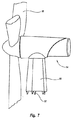
次に図7を参照すると、風力タービン14が従来の管状円筒形ベイ部55に固定されている。円筒形ベイ部55は一実施形態において、鋼鉄から構築され、下方に延在する複数の鋼鉄タブ部材37(137)を有する。各タブ部材37(137)は、最上ベイ部分19の長手方向部材20(120)の上方端部と相互接続するように構成される。接続は、溶接、ボルトまたは長手方向継手部31(131)に関して上述した同様のピン接続手段を使用して形成される。風力タービン14は、標準的手段、または風力タービンを従来の管タイプのタワーに装着するための当業者に知られた接続システムを使用して円筒形ベイ部55に回転可能に固定される。
Referring now to FIG. 7, the
上述のように、構造タワー10を構成する種々の部材を構築するために鋼鉄以外の物質を使用することは、特にタワー頂部付近のベイ部12を構成する長手方向および対角線部材に関して有利であることを証明することができる。例えば複合物質を使用して対角線または水平方向部材を構築することは、実質的にタワーの重量を減少させ、剛性特性、したがってタワーに関連する共鳴周波数を変えることができる。図8を参照すると、本発明の複合対角線部材226の実施形態が、この対角線部材226をそれぞれの隣接する長手方向部材に固定する手段と共に記載されている。対角線部材226は、本発明のコネクタ27を一端に装着して示されている。対角線部材226は、複合物質の管状部材60を含む。コネクタ27は、管状部材60の両端に固定される。コネクタ27は、内側スリーブ62および外側スリーブ64を含む。内側スリーブ62は、スリーブの外径67に外側接触面66を形成する。同様に外側スリーブ64は、スリーブの内径69に内側接触面68を形成する。管状部材60はまた、管状部材60の両端に内側接触面70および外側接触面71を形成する。以下に記載するように組み立てられる際、内側スリーブ62、外側スリーブ64および管状部材60の寸法は、コネクタ27と管状部材60の間に締まりばめを形成するように選択される。一実施形態において、管状部材60の内側接触面70の直径は約10インチであり、管状部材60の外側接触面71の直径は約11.5インチであり、その結果壁の厚さは約1.5インチになる。一実施形態において、約10/100から20/100(0.01から0.020)インチの消極的寸法公差が好ましい。上述の接触面直径と一致して、次いで外側スリーブの内径69は一実施形態において、約11.48から11.49インチであり、内側スリーブ62の外径67は、約10.01から10.02インチである。この実施形態における構造タワー10の管状部材60の長さは、約3から約8メータの範囲であり、タワー内でのその配置に左右される。本実施形態における種々の接触面66、68、70、71のそれぞれの軸方向の長さ61は、約4から約6インチである。上述の寸法は本実施形態で、構造タワー10の上方ベイ組立体に配置される対角線部材226用に使用される。しかしながら寸法は、構造タワーの任意の特定の用途に関する高さ、直径および予想される荷重または操作上の条件によって増減することがある。
As noted above, the use of materials other than steel to build the various members that make up the
複合管状部材60に対してコネクタ27を組み立てる一つの方法を以下に記載する。外側スリーブ64は、管状部材60の外側接触面71を収容するために内側接触面を拡張させるのに十分高い温度まで加熱される。同様に内側スリーブ62は、管状部材60の内側接触面70を収容するために外側接触面66を収縮させるのに十分低い温度まで冷却される。一実施形態において、外側スリーブ64は華氏約300度(300°F)の温度まで加熱され、これは内側接触面68の所望通りの拡張に作用するのに十分な高温であるが、スリーブと部材とが接合される際、管状部材60の複合基質に損傷を与えるほどの高温ではない。同時に、内側スリーブ62は華氏約―300度(−3500F)の温度まで冷却される。内側スリーブ62および外側スリーブ64に関して所望の温度が実現すると、構成要素は次いで一緒に接合され、室温と均衡を保つことが可能になる。温度が均衡を保つようになると、外側および内側スリーブは非常に高い半径方向の圧力または応力で複合管状部材60を締め、圧縮および伸張の両方における極めて大きい荷重を伝送できるように接触面に締まりばめを形成する。
One method for assembling the connector 27 to the composite tubular member 60 is described below. The
コネクタ27の一実施形態は、内側スリーブ62に外側に延在するリップ部分76、および外側スリーブ64に内側に延在するリップ部分77を含む。内側スリーブ62のリップ部分76は、管状部材60の外周壁領域78にわたって延在する。同様に外側スリーブ64のリップ部分77は、内側スリーブ62のリップ部分76とほぼ同一の距離ではあるが、反対方向に延在する。内側および外側スリーブ62、64の重なるリップ部分76、77は、複合対角線部材226が伸張状態で配置される際、管状部材60の内側接触面と外側接触面の間により良好に摩擦荷重を分配するように機能する。上述の接続を実現するための方法と同様に、複合対角線部材226のコネクタ27は、ボルト、溶接、または例えば対角線継手41(141)に関して記載された同様のピン接続手段などのピン継手を使用して長手方向部材20(120)に固定される。
One embodiment of the connector 27 includes a lip portion 76 that extends outwardly to the
本発明の構造タワー10の構築における複合管状部材60の使用の上述の記載は、複合対角線部材226におけるこのような複合部材60の使用に焦点を合わせている。同様の原則が長手方向およぎ水平方向部材にも概ね適応される。例えば図9および10は、同様の重量の削減の利益を実現するために、複合長手方向部材220および複合水平方向部材222それぞれを構築するのに使用される複合管状部材を示している。上述の鋼鉄部材用の複合部材の代替は、構造タワー10内のそれらの位置に関係なく、構造タワー10全体に、すなわち長手方向、対角線および水平方向部材の任意の1つまたは複数の、あるいはすべてさえも選択的に形成することができる。例えば図9および10は、上述の複合対角線部材226と同様の、それぞれ典型的ベイ組立体ベイ部分12を呈する長手方向部材20および水平方向部材22の代替の複合部材を示している。
The above description of the use of composite tubular member 60 in the construction of
図9を参照すると、例えば複合長手方向部材220は、端部コネクタ225を有する複合支柱として示されている。端部コネクタは、複合対角線部材226に関する締まりばめコネクタ27に関する上述の方法と同様の方法で複合長手方向部材220に固定される。しかしながら、一組の端部フランジ端部44を有する代わりに、端部コネクタ225は、対向する端部コネクタ225の対応するフランジにボルト留めされるまたは溶接されるフランジ221を有する。あるいは端部コネクタ225は、ボルト、または長手方向継手31(131)に関連して上述したようなピン接続組立体を使用して接続部を固定することができる上述したものと同様の雄および雌タブ構造を含む。同様の方法で図10は、ピン留め、ボルト留めされるまたは、さもなければ鋼鉄の長手方向部材20に固定される端部コネクタ223を有する複合水平方向部材222を示す。図9および10の両方において、対角線部材229は鋼鉄部材または、代替として複合対角線部材226であり、対角線継手41(141)の構築に関して上述した技法を使用して、長手方向部材20または端部フランジ225にピン留めされる。しかしながら図9に示すように、複合長手方向部材220が使用される場合、複合管状部材に対向するように対角線部材26(226)を直接端部フランジに固定することが好ましい。図9および10は、複合長手方向部材220または複合水平方向部材222のいずれかを有するベイ部分をそれぞれ示すが、別の実施形態は複合長手方向220、対角線226および水平方向222部材、またはそれらの組み合わせを使用して構築される構造タワー10全体を企図することを理解するべきである。
Referring to FIG. 9, for example, composite
本発明の別の実施形態において、例えば粘性または粘弾性の減衰部材、あるいはより一般的には減衰部材または支柱など振動を減衰するように構成される1つまたは複数の長手方向、対角線または水平方向部材を構造タワー10に組み込むことにより、通常の状況下で、および特に高度の大きい風力タービン用途が考えられる厳しい作動条件に応じてタワーに対する構造上の完全性の強化を実現する。減衰(または減衰された)支柱または部材の種々の実施形態が本明細書で考察されている。この考察は、大まかに2種類の減衰支柱に集中する。第1の種類は、減衰部材が有意な剛性および減衰を含むように、1つの支柱に一体式の平行ばねおよびダッシュポット構成を形成するために複合物または他の剛性部材と共に粘弾性物質の使用を検討する。第2の種類は、有意な剛性および減衰を含むように、平行ばねおよびダッシュポット構成を形成するために1つの部材に一体式に配置される粘性または水圧式流体減衰装置の使用を検討する。あるいは、部材を形成する剛性を排除することによって、ダッシュポットが主に減衰を実現することになる。例えば磁力など減衰を及ぼす他の手段が当業者に知られているが、本明細書に記載の種類は、本発明の構造タワー10の高所の風力タービン用途で使用するのに有益であることを証明してきた。しかしながらこれらの考察は、本発明の範囲内にあるダッシュポット特性を有する同様の減衰機構の使用に限定するもの、あるいは除外するものとして解釈されるべきではない。さらにこの考察は、減衰された対角線部材に主に向けられた記載と共に進行する。しかしながら上述の考察から、このような記載は長手方向および水平方向部材にも概ね適用されるので、上述の本明細書に記載される原理は全体として構造タワー10の長手方向、対角線または水平方向部材のそれぞれに適用する際、減衰された対角線部材に関する記載は、本発明の範囲を限定するものとして解釈されるべきではない。
In another embodiment of the invention, one or more longitudinal, diagonal or horizontal directions configured to damp vibrations, such as viscous or viscoelastic damping members, or more generally damping members or struts, for example. By incorporating the components into the
次に図11を参照すると、一端に本発明のコネクタ127が装着された減衰対角線部材126の一実施形態が示されている。図11に示す実施形態は、内側管状部材81および外側管状部材82を含む。内側管状部材81、82は一実施形態において、異なるパターンで層をなすファイバを有する複合ファイバ物質から構成される。内側複合管状部材81と外側複合管状部材82の間に粘弾性物質の層83が挟まれている。内側複合管状部材81と外側複合管状部材82の間に挟まれる粘弾性物質の層83の組み合わせが、構造タワー10の振動を減衰する複合減衰支柱を形成する。コネクタ127は、単一の複合管状部材60を有する複合対角線部材226に対する締まりばめに関して上記に記載したのと同様の方法で、内側複合管状部材81、外側複合管状部材82と、粘弾性物質の層83との複合物に固定される。減衰対角線部材126の寸法は、上記の複合対角線部材226に関する寸法と同一でありうる。粘弾性層の厚さは、先に記載した対角線部材226と一致してそれぞれ複合管の壁の厚さが約3/4インチであり、全体の壁の厚さは約1.5インチになるものと比較すると相対的に小さく、一実施形態ではほぼ約0.2ミリメータ(0.2mm)である。さらに本実施形態の粘弾性層は、コネクタ領域内には延在しない。所望であれば、ほぼ粘弾性層の厚さの複合物などの好適な物質の非常に薄い軸方向の鍔が、粘弾性層がコネクタ領域に延在する代わりにコネクタ領域に延在してよい。この後者の構成は、粘弾性層がほぼ1ミリメータ以上の厚さの実施形態に関して有益であろう。
Referring now to FIG. 11, there is shown one embodiment of a damped
振動を減衰する複合減衰部材(または支柱)の使用は、その開示が、参照により本明細書に組み込まれ米国特許第5、203、435号(Dolgin)に提案されている。複合減衰支柱を形成する方法はまた、その開示が、参照により本明細書に組み込まれる米国特許第6、048、426号(Pratt)、米国特許第6、287、664号(Pratt)、米国特許第6、453、962号(Pratt)、および米国特許第6、467、521号(Pratt)に開示されている。例えば減衰対角線部材126など本発明の複合減衰支柱は、以下の構造上および機能上の特性を有して構築される。内側および外側複合管状部材81、82は、管内のファイバ基質が画定されたパターンに従うように形成され、内側複合管状部材81のパターンは、外側複合管状部材82のパターンと位相がずれている。詳細には有益なパターンは、一定または変化する周波数、および軸方向の長さ、または部材の荷重方向に沿った振幅を有する正弦波を含む。代替のパターンは、のこぎり歯状(またはV字型)波およびらせん状うずまきを含む。このパターンの1つの特徴は、内側管のパターンの少なくとも一部が外側管のパターンと位相がずれている、または外側管のパターンに対して位相移動されている点である。このことにより圧縮または伸張のいずれかにおいて複合支柱が荷重される際、生成されるべき剪断応力が粘弾性層83内に生じることになる。剪断応力は粘弾性層内に内部摩擦を生成し、この内部摩擦が後に周囲環境に消散する熱を生成することにより、例えば減衰対角線部材126の使用によってなど減衰支柱の使用によって構造タワー10の減衰に作用する。内側および外側管のパターンに関する代替の実施形態は、減衰支柱の端部に圧縮または伸張力が加わる際、粘弾性層内の剪断応力に作用する任意のパターンを含む。この代替のパターンは、例えば複合管状部材81、82の軸方向、らせん状または環(または外周上)の方向にわたる複合ファイバの層によって生成することができる。
The use of composite damping members (or struts) to damp vibrations, the disclosure of which is incorporated herein by reference and is proposed in US Pat. No. 5,203,435 (Dolgin). Methods for forming composite damping struts are also disclosed in US Pat. No. 6,048,426 (Pratt), US Pat. No. 6,287,664 (Pratt), US Pat. No. 6,453,962 (Pratt) and US Pat. No. 6,467,521 (Pratt). The composite damping strut of the present invention, such as the damping
さらに図11を参照すると、内側複合管状部材81は、複合(または強化)ファイバ87の第1のパターンを含む。この強化ファイバ87の第1のパターンは、管の内側および外側円周上(同様に管の内側の厚み)の周りに半径方向に、および管の長さに沿って軸方向に延在する。一実施形態において、強化ファイバ87の第1のパターンは、一定の波長(または周波数)および振幅(このパターンの一部のみが示されている)を有する正弦波の形態である。外側複合管状部材82は、強化ファイバ88の第2のパターンを含む。この強化ファイバ88の第2のパターンは、やはり、一定の波長および振幅(この第2のパターンの一部は、点線を使用して内側管状部材上に重ねられて示されている)を有する正弦波の形態である。本発明の範囲から逸脱することなく、他のパターンを使用することができる。強化ファイバ87、88の第1および第2のパターンは共に一実施形態において、管状部材81、82の全長に沿って互いに180度位相がずれている。しかしながら、このパターンは完全に180度位相がずれる必要がないことを当業者は理解するであろう。さらに粘弾性層は単に、減衰が生じる長さの一部に沿って存在する必要がある。減衰対角線部材126が圧縮または伸張状態で荷重される際、正弦波のピーク、および谷ならびに他の部分は互いに対して移動することにより粘弾性層内の剪断応力に作用し、その結果振動が減衰される。しかしながら当業者は、複合ファイバの任意のパターンが粘弾性層内の剪断応力およびその結果の減衰に作用し、剪断応力が増大する一方、減衰も増大することを認識するであろう。
Still referring to FIG. 11, the inner composite
図11は、一組の複合管状部材の間に挟まれる粘弾性物質の単一の層を示しているが、当業者には、付加的粘弾性物質および複合管状部材も減衰に作用するにの使用することができることが明らかであろう。図12を参照すると、例えば上記の複合減衰支柱の代替が示されている。詳細には、代替の複合減衰支柱136は、第1の複合管状部材183、第1の部材内に配置される第2の複合管状部材184、および第2の部材内に配置される第3の複合管状部材185を含む。第1および第2の複合管状部材183、184と第2の粘弾性層の間に配置される第1の粘弾性層188は、第2および第3の複合管状部材184、185の間に配置される。第1の複合管状部材185は、帯鋼のように、または外周の周りに円周上に、および管の長さに沿って軸方向に延在する強化ファイバ(図示せず)の第1のパターンを含む。強化ファイバの第1のパターンは一実施形態では、一定の波長(または周波数)および振幅数を有する正弦波の形態である。第2の複合管状部材184は一実施形態では、第1のパターンの強化ファイバと位相がずれている第2のパターンの強化ファイバを含む。第3の複合管状部材183は一実施形態では、第2のパターンの強化ファイバと位相がずれている(および所望であれば、第1のパターンの強化ファイバと完全に同相でありうる)第3のパターンの強化ファイバを含む。例えば代替の対角線部材136などの複合減衰支柱が圧縮または伸縮状態で荷重される際、正弦波パターンのピーク、谷および他の部分が互いに対して位置を変えることにより粘弾性層内の剪断応力に作用し、その結果振動を減衰する。しかしながら先の実施形態と一致して、当業者は、種々の管状部材内の複合ファイバの任意のパターンが粘弾性層内の剪断応力およびその結果の減衰に作用し、剪断応力が増大する一方、減衰も増大することを認識するであろう。
Although FIG. 11 shows a single layer of viscoelastic material sandwiched between a set of composite tubular members, those skilled in the art will appreciate that additional viscoelastic materials and composite tubular members also act on damping. It will be clear that it can be used. Referring to FIG. 12, for example, an alternative to the composite damping strut described above is shown. Specifically, the alternative
すでに述べたように、本発明の構造タワー10の構築における減衰複合部材の使用の上記の記載は、対角線部材減衰対角線部材126、136におけるこのような複合部材の使用に焦点を当てている。しかしながら同様の原理は、長手方向および水平方向部材の両方に概ね同様に適用される。したがって図9および10に示されるように、長手方向および水平方向複合部材を構築するための複合管状部材の使用に関する上記の記載は、減衰長手方向および水平方向複合部材にも等しく適用される。さらに、上記の鋼鉄部材(または非粘弾性の減衰された複合物)の減衰複合部材の代替は、構造タワー10全体で、すなわち長手方向、対角線、および水平方向部材の1つまたは複数、またはすべてさえも選択的に形成することができる。
As already mentioned, the above description of the use of damping composite members in the construction of the
構造タワー10を減衰するための種々の代替の実施形態またはシステムは、本発明の範囲内にあるように企図されている。図13を参照すると例えば、代替の減衰支柱226が示されている。減衰支柱226は、内側管状部材227、外側管状部材228、および内側および外側管状部材227、228の間に配置される粘弾性(またはゴム様)物質229を含む。内側および外側管状部材227、228は、上記に考察したパターンに配置されるファイバを有する複合物質を使用して構築される。好適な代替物は、鋼鉄、アルミナムまたはプラスチックを含んでよく、粘弾性層を囲繞する面に内接する上記に記載のパターンと同様のパターンを有する。あるいはパターンをまったく使用しない場合、剪断応力の度合いが低下し、結果として減衰の程度が低下することになる。内側および外側管状部材227、228は、上記の方法で減衰支柱226を構造タワー10の長手方向部材長手方向部材20に接続するためのコネクタ部222、223を含む。内側および外側管状部材227、228は、減衰構造体226が伸張または圧縮を受ける際、互いに対して軸方向に自由に平行移動する。減衰支柱が伸張または圧縮を受ける際、粘弾性物質内に剪断応力が生じ、周囲環境に消散する熱を生成することにより構造タワー10内の減衰に作用する。
Various alternative embodiments or systems for dampening the
図14を参照すると、本発明の減衰支柱に対する別の代替が示されている。代替の減衰支柱326は、共に網掛けされ粘弾性(またはゴム様)物質の層を挟む一組の平板部材327、328を含む。平板部材327、328は、ここではパターンが基本的に軸方向面に対向する平坦な面を呈することを除いて、上記のパターンに配置されるファイバを有する複合物質を使用して構築される。好適な代替物は、鋼鉄、アルミナムまたはプラスチックを含み、接触面に内接するパターンを有する。コネクタ部322、323は、上記の方法で減衰支柱326を構造タワー10の長手方向部材20に固定する。平板部材327、328は、減衰支柱が伸張または圧縮を受ける際、互いに対して長手方向に平行移動するための好適な手段(図示せず)によって限定される。減衰支柱が伸張または圧縮を受ける際、粘弾性物質内に剪断応力が生じ、周囲環境に消散する熱を生成することにより構造タワー10内の減衰に作用する。
Referring to FIG. 14, another alternative to the damping strut of the present invention is shown. An alternative damping
本発明の構造タワー10の振動を減衰するために、種々の他の代替の減衰実施形態を使用することができる。例えば、精密トラス構造で使用するために開発されたd支柱技術に適用されるような粘性または水圧式手段を振動を減衰するために使用することができる。「d支柱」技術は例えば、参照によりその開示が本明細書に組み込まれるAnderson et al.、"Testing and Application of a Viscous Passive Damper for Use in Precision Truss Structures、" pp. 2796-2808 (AIAA Paper、1991)に記載される。d支柱技術は、内側と外側の管支柱構造で構成された粘性または水圧式減衰装置を採用する。図15および16を参照すると、外側管状支柱400(500)はアルミナムなどの物質で構築され、内側管状支柱402(502)は外側支柱より高い剛性または弾性係数を有する物質で構築される。内側および外側支柱400、402(500、502)間の効果的な剛性(または弾性係数を乗じた横断面領域)の差が大きいほど、実現する減衰が大きくなる。ダッシュポットは上記の2つの実施形態、すなわち図15および16に示す実施形態から派生し、外側管状支柱400(500)に与える剛性を排除することにより、減衰部材の効果的な剛性をゼロ付近まで減少させ、結果として生じる部材が主として減衰に作用することができる。一実施形態において内側支柱402(502)は、共通端部404(504)で外側支柱400(500)に接続される。内側支柱402(502)の反対側の端部406(506)は、ふいご組立体407(507)、または他の可撓性部材、微小な通気孔409(509)、およびばね部材410(510)とピストン411(511)構成または同様のアキュムレータ装置を含む粘性または水圧式減衰装置406(506)に装着される。外側支柱400(500)の端部は、例えば対角線継手41、141に関する上記の技法、または他の好適な手段を使用して端部コネクタ421、422(521、522)を介して長手方向部材20に接続される。圧縮または伸張荷重の下で、外側支柱400(500)が軸方向に引っ張られることによって内側と外側の支柱の間に相対的ずれが生じ、これにより粘性または水圧式減衰装置406(506)が作動する。微小な通気孔409(509)を通って移動する流体420(520)によって粘性流体内に剪断力が生じ、これが構造タワー10に対する減衰を実現する。例えば、ばね部材410(510)およびピストン411(511)などの粘性または水圧式減衰装置のアキュムレータ部分は、図16に示すようなd支柱内、または図15に示すようなd支柱の外側のいずれかに配置することができる。あるいは、粘性または水圧式減衰装置406(506)のアキュムレータ部分は、内側と外側の支柱400、402(500、502)の間に配置することができる。当業者は、減衰装置のばねおよびピストン部分は、容易に知られた同様の水圧式アキュムレータで代替することができることを認識し、さらに、ばね410にかかる張力、またはガスアキュムレータに対するガス充填圧力は、伸長荷重下での減衰が低下するのを防止するために、流体中に気泡が形成するのを緩和させるのに十分大きくなければならないことを認識するであろう。
Various other alternative damping embodiments can be used to damp vibrations of the
図17を次に参照すると、粘性減衰支柱または部材の別の実施形態が示されている。外側管状支柱600は、内側管状支柱602を収容する。上述のd支柱の実施形態と同様に、外側管状支柱600はアルミナムなどの物質で構築され、内側管状支柱602は、例えば鋼鉄などの外側支柱より大きな剛性または弾性係数を有する物質で構築される。内側および外側支柱600、602間の効果的な剛性(または弾性係数を乗じた横断面領域)の差が大きいほど、実現する減衰が大きくなる。当業者は、ダッシュポットのみを形成するための代替の構成は、基本的に外側管状支柱600の除去を含むことを認識するであろう。外側管状支柱600は、第1端部601および第2端部603を有する。端部キャップ605は、外側管状支柱600の第1端部601に配置される相補的フランジ部材と係合するように構成されるフランジ部材607を有する。一連のボルト609を使用して、端部キャップ605を外側管状支柱600の第1端部601に緊密に固定する。内側管状支柱602は、例えば溶接など任意の好適な手段を使用して端部キャップ605に固定される第1端部617を有する。内側支柱は、それ自体接続ロッド620に装着される第2フランジ619の形態の第2端部を有する。接続ロッド620の第1端部は、例えばフランジ619の対応する雌ねじ込み部分623にねじ込まれる接続ロッドのねじ込み雄部分621などの任意の好適な手段を使用して、第2のフランジ619に固定される。
Referring now to FIG. 17, another embodiment of a viscous damping strut or member is shown. The outer tubular strut 600 houses the inner
第2の端部キャップ630は、外側管状支柱600の第2端部603に配置される相補的フランジ部材と係合するように構成されるフランジ部材631を有する。一連のボルト609を使用して、端部キャップ630を外側管状支柱600の第2端部603に緊密に固定する。密封筐体624は、外側管状支柱600の第2端部603に配置されるフランジ部材の内側部分626に固定される。密封筐体624は、一連のボルト637または他の好適な手段を使用してフランジ部材の内側部分626に固定される。密封筐体は、接続ロッド620の外側壁面に適合するように厳密に機械加工される内側壁面643を有する。シール641は、例えば粘性または水圧式流体などの減衰流体が2つの構成要素の間に存在する境界面に沿って漏出するのを回避するために、接続ロッド620と密封筐体624の間に配置される。2つの部品の相対的移動による構成要素の磨耗を回避するために、ポリマー様の磨耗バンド645が密封筐体624と接続ロッド620の間に配置される。あるいは、内側壁面643の直径と接続ロッド620の外側壁面の間に空隙が形成されるように、内側壁面643の直径を増大することができる。分離によって形成される空隙は、例えばほぼその長さに沿って接続ロッド620と密封筐体624の両方に結合されるふいごまたはゴム物質などの適合機構によって塞がれ、これによりシール641の必要性を排除することができる。この適合物質の代替は、非剛性物質が相対的移動に適合するように伸びることができるように、ほぼ1インチを超えないわずかなずれが生じる減衰支柱での使用に特に有益である。またシール641を排除することにより、流体を密封するための非摺動面が形成され、これにより長期間にわたる耐用期間特性が実現する。ピストン622は、ボルト627または一連のボルトを使用して接続ロッド620の第2端部に固定される。第2端部キャップ630は、ピストン622の外側壁面635に適合するように厳密に機械加工される内側壁面633を有する。
The
減衰流体650(例えば粘性または水圧式流体)はピストン620、第2端部キャップ630および密封筐体624によって形成される第1空洞651および第2空洞653内に包含される。減衰支柱が圧縮または伸張荷重を受ける際の内側支柱602と外側支柱600の間の相対的ずれによって、ピストン620が第2端部キャップ630のベース部分632に向かって、またはそこから離れて並行移動する際に減衰が生じる。より詳細には、ピストン620がベース部分632に向かって平行移動する際、第1空洞651からの流体が、第2端部キャップ630の内面壁633とピストン620の外面壁635の間の空間によって画定される周囲領域を介して第2空洞653内に押し込められる。あるいは、一方の面から他方の面までピストン620の本体を通る小さな導管または穴を機械加工することができ、1つまたは複数の小さな導管を介してピストン620の片側から他の側に流体が流れる際に減衰が生じる。アキュムレータ660はダクト662を介して第1空洞に接続される。あるいは、アキュムレータ660は支柱内の種々の位置で内側に配置されてよく、ダクト662は第2の流体空洞653に接続されてよい。アキュムレータ660または同様の装置は、接続ロッド619の第2の流体空洞653内に占める空間容積を収容することが要求される。より詳細には、ピストン620がベース部分632に向かって一定の距離平行移動する際、第1空洞651の容積は減少し、第2空洞653の容積は増大する。しかしながら、第2空洞653内に接続ロッド619が存在することから、ピストン620の平行移動により第1空洞651から移動する流体の容積は、第2空洞653内に生成する空間の容積より大きい。ロッドが第2空洞653内に平行移動する際、接続ロッドが占有する第2空洞653内の空間の容積と容積が等しい余剰流体は、ダクト662を通ってアキュムレータに移送される。第1空洞651とアキュムレータ660の間に配置される制御弁664は、減衰支柱を圧縮する際、すなわちピストン620がベース部分632に向かって平行移動する場合、流体がアキュムレータに流れ込むことが可能なるように機能し、減衰支柱が伸張する際、すなわちピストン620がベース部分632から離れて平行移動する場合、流体がアキュムレータから流出し、第1空洞651に戻ることが可能になるように機能する。接続ロッド619に付加的流体を与えるための上述のアキュムレータの記載は、補給流体を提供するために必要な原則的な機能の例示である。しかしながら当業者は、適切な作動をもたらす適切な比率でこの流体を提供することができる他の装置または機構が知られていることを理解するであろう。
Damping fluid 650 (eg, a viscous or hydraulic fluid) is contained within first and second cavities 651 and 653 formed by piston 620,
先に考察したように一実施形態において、流体650は、第1空洞651から第2空洞653に転送され、第2端部キャップ630の内面壁633とピストン620の外面壁635の間の空間を通って逆に転送される。以下に考察するように、この流体転送様式により流体がピストン本体を通って延在する小型の導管を通って転送される場合よりも、減衰支柱が温度変化の影響を受けにくくなる。より詳細には減衰効果は、温度の関数として生じる減衰流体の粘性の付随的な変化による温度の変化の影響を受ける場合がある。例えば温度が上昇すると減衰流体の粘性は概ね減少し、ピストン620の所与の移動に関して減衰の効果が少なくなることになる。このような傾向は、ピストン620が端部キャップ630(またはピストンに隣接する円筒形壁)を構築するのに使用される物質より高い熱膨張係数を有する物質を使用して構築される場合には無効になりうる。一実施形態において、例えばピストン620はアルミナムを使用して構成され、端部キャップ630は鋼鉄を使用して構築される。アルミナムは鋼鉄が有するよりも高い熱膨張係数を有し、このことは、アルミナムが温度の関数として鋼鉄のものよりも大きな比率で膨張し収縮することを表す。熱膨張比率におけるこの可変性によって、第2端部キャップ630の内面壁633とピストン620の外面壁635の間の空間が、温度が特定の予定温度に対して降下する際に増大し、温度が特定の温度に対して上昇する際に減少するようになる。2つの移動面の間の流体中に生成される剪断力によって生じる減衰効果は、この面の間の空間または距離に一部左右され、距離が大きくなると減衰が小さくなる。したがって、温度が上昇する際、流体の粘性が減少することによる減衰効果の減少は、第2端部キャップ630の内面壁633とピストン620の外面壁635の間の空間または距離の減少によって部分的に相殺される。本発明のこの特徴は、一日のまたは周期的な気候の変化によって生じる温度の変化による減衰支柱の感度を減少させる点で特に有益である。
As discussed above, in one embodiment, the fluid 650 is transferred from the first cavity 651 to the second cavity 653 and moves through the space between the
上述の記載は、構造タワーの1つまたは複数のベイ組立体内に配置される減衰または非減衰の長手方向、対角線、および水平方向部材を含む構造タワーを構築する種々の様式および方法に関する詳細を提供する。しかしながら当業者は、上記の組立方法の種々の代替を認識するであろう。例えばベイ部分12は、ベイ部分12のそれぞれの面で、長手方向部材20の組の間に配置される単一の対角線部材26を有するように示されている。しかしながら当業者は、対角線部材26の組は、交差形態で長手方向部材20の組の間に配置されてよく、タワー空間の内側を横切って長手方向部材の任意の組の間に配置されてよく、および単一様式の対角線部材26の配向は組み合わせることができる、すなわち対角線部材は、時計回りおよび反時計周りの方向の両方で(または隣接するベイ部がタワー10の中央軸に沿って配列される際、右周りおよび左周りの構成で)配置することができることを理解するであろう。あるいは対角線部材は、ベイ組立体の個々の面から除去されてよく、長手方向部材は1つまたは複数のベイ組立体におよび、水平方向部材は1つまたは複数のベイ組立体から選択的に除去されてよい。次に図18から24を参照すると、減衰および非減衰支柱または部材の組み合わせを含む構造タワーの他の種々の代替の実施形態が示され記載されている。これらの例示および記載は、包括的な形態、すなわち特有の部材の特定の詳細を示していない形態で提供されており、減衰および非減衰部材の種々の構築または用途に対して上記に提供される詳細は、以下で本明細書に提供される種々の用途に適用可能であることを理解するべきである。
The above description provides details regarding various manners and methods of constructing a structural tower including attenuating or non-damping longitudinal, diagonal, and horizontal members disposed within one or more bay assemblies of the structural tower. To do. However, those skilled in the art will recognize various alternatives to the assembly methods described above. For example, the
図18を参照すると、例えばベイ組立体712の代替の実施形態が示されている。ベイ組立体712は、上記の1つまたは複数の種々の実施形態を使用して構築される非減衰の例えば鋼鉄、アルミナムまたは複合物の長手方向720、対角線726および水平方向722部材を含む。一実施形態においてベイ組立体712はさらに、非減衰対角線部材726のそれぞれに隣接して並行に配置される一連の減衰対角線部材730を含む。この実施形態に関して構造タワーが荷重されることを条件とする場合、非減衰対角線部材726は、対角線部材726が受ける圧縮または伸張荷重のいずれかによる軸方向のわずかな偏向を受ける。非減衰対角線部材726が軸方向でこのような偏向を受ける際、隣接する減衰部材730は同様に軸方向に偏向し、これにより消失されるべきエネルギーを生じる。非減衰および減衰対角線支柱726、730のこの点に関する構成は、並行に接続され動的に荷重される一次元のばねおよびダッシュポットと概ね類似と考えることができる。上記の任意の種々の減衰部材は、図18に示す減衰対角線部材730用に採用することができるが、代替の実施形態は、ほとんど純粋な減衰および非常に低い剛性を実現する大型の緩衝器(またはダッシュポット)の使用を企図する。実際当業者は、緩衝器(ダッシュポット)と剛性の非減衰部材の並行した一列の配置がこのような部材のそれぞれがばね様剛性要素(非減衰部材)および減衰部材の両方を含み、例えば粘性減衰部材の外側管状部材400、500、600が非減衰剛性構成要素を提供し、内側管状部材402、502、602および水圧式減衰装置構成要素が減衰構成要素を提供する上記の減衰部材と類似であることを認識するであろう。この考察は、以下に呈示される種々の他の代替に適用される。主に減衰目的の緩衝ダッシュポットは、本明細書で開示されるばね様およびダッシュポット様特性を共に有する減衰部材または支柱とは対照的に、例えばニューヨーク州、北トナワンダのTaylor Device社から商業的に入手可能である。
Referring to FIG. 18, an alternative embodiment of a bay assembly 712 is shown, for example. The bay assembly 712 includes non-damped, eg, steel, aluminum or composite longitudinal 720, diagonal 726 and horizontal 722 members constructed using one or more of the various embodiments described above. In one embodiment, the bay assembly 712 further includes a series of damped
次に図19を参照すると、図18に示されるものの代替の実施形態は、隣接する非減衰対角線支柱726の上方または下方に配置される減衰対角線支柱730、および時計回り741または反時計周り743の方向で、またはそれらの組み合わせのいずれかで配向される減衰および非減衰支柱の隣接する組を企図している。さらに図19に示すように、ベイ組立体の代替の実施形態は、ベイ組立体の1つまたは複数の面745で減衰および非減衰対角線支柱の組を使用し、ベイ組立体の他の面746、747は、1つまたは他の減衰または非減衰対角線支柱を含む、あるいは減衰または非減衰対角線支柱のいずれも含まないことを企図している。
Referring now to FIG. 19, an alternative embodiment to that shown in FIG. 18 is that of an attenuated
次に図20を参照すると、ベイ部の支柱の構成のさらに別の代替の実施形態が示されている。この実施形態においてベイ組立体762は、1つまたは複数の上記の種々の実施形態を使用して構築される非減衰長手方向770、対角線776および水平方向772部材を含む。一実施形態においてベイ組立体762はさらに、非減衰対角線部材776のそれぞれと隣接してほぼ垂直に配置される一連の減衰支柱780を含む。減衰支柱780は、隣接する長手方向部材770に接続する第1端部781、およびそれぞれが上記の方法および技法を使用して構築することができる非減衰部材である一組の増幅部材785に接続する第2端部782を有する。一組の増幅部材785のそれぞれ1つは一実施形態では、隣接する対角線部材776に対して約5から約15度の角度で配置される。増幅部材785の第1端部786および減衰支柱の第2端部782は、ヒンジ継手で共に結合される。この実施形態に関して、構造タワーが荷重を受けることを条件とする際、対角線部材776は、対角線部材776が受ける圧縮または伸張荷重のいずれかによるわずかに軸方向の偏向を受ける。対角線部材776がこのような軸方向の偏向を受ける際、隣接する増幅部材785および減衰支柱780を接続するヒンジ継手790は、荷重が伸長か圧縮かによってそれぞれ対角線部材776に向かってまたはそこから離れて平行移動する。ヒンジ継手790 の平行移動は、減衰支柱780の軸方向の偏向につながり、これにより消散するべきエネルギーが生じる。
Referring now to FIG. 20, yet another alternative embodiment of a bay post configuration is shown. In this embodiment, the
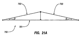
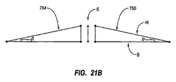
次に図21Aを参照すると、増幅部材785が減衰のために提供する増幅効果は、ピタゴラスの直角三角形の定理を参照することにより最適に理解される。具体的には底辺751を有する三角形750が示されている。三角形750の底辺751は、図20に示される非減衰対角線部材776に関連付けることができる。同様の様式で、図20に示される増幅部材785の組は、三角形750の残りの2辺752、753(長さが同等である必要はない)と関連付けることができる。角βおよびθ(これも同等である必要はない)は、増幅部材785が非減衰対角線支柱776に対して位置するそれぞれの角度と関連付けることができる。図21Bに示されるように、この構成は各三角形が斜辺H、底辺Bおよび高さSを有する2つの直角三角形754、755を形成する。三角形755に焦点をおくと、斜辺Hが実質的に剛性であるとすると、圧縮または伸張荷重により底辺Bの長さが変化することにより、高さSの長さが対応して変化することになる。基礎代数は、この点に関して以下の関係式dS/dB ≒ - (B/S) ≒ - (1/tan θ)を与える。したがって初期のBに対する小さい初期のS(または小さいθ)に関して、Sの変化は、Bの変化と比較して相対的に大きくなる。換言すると、非減衰対角線支柱776の長さの軸方向のわずかな偏向により、減衰支柱780が軸方向に相対的に大きく移動することになり、それらの間に形成される角度は小さくなる。一実施形態において増幅効果は、鋼鉄などの比較的高い弾性率を有する物質を使用して増幅部材785を構築し、アルミナムなどの比較的低い弾性率有する物質を使用して非減衰対角線部材776を構築することによって確実となる。
Referring now to FIG. 21A, the amplification effect that
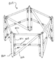
次に図22を参照すると、ベイ部812の別の実施形態が示されている。ベイ部812は、1つまたは複数の上記の種々の実施形態を使用して構築される非減衰長手方向820、対角線826および水平方向822部材を含む。ベイ部812はさらに、増幅部材821および減衰支柱823を含む。しかしながら増幅部材821および減衰支柱823は、、例示の実施形態において増幅部材821は、対角線部材ではなく隣接する長手方向部材820に配置されることを除いて上記と同様の様式で構築され機能する。
Referring now to FIG. 22, another embodiment of the
次に図23および24を参照すると、減衰対角線部材230および鋼鉄の長手方向部材231を有する改良された従来型管タワー232が示されている。改良された従来型タワー232は、典型的な様式で組み立てられる従来型管部材234、235を有する。上方の鋼鉄またはコンクリート管部材235は、複数の長手方向部材231の端部を受けるように構成される鋼鉄の輪または他の好適な部材を有する。対角線支柱、例えば減衰または非減衰対角線支柱、あるいはダッシュポットとばね部材との組み合わせは、ピン留め対角線継手41、141に関する上記の方法、またはボルト、溶接またはフランジなどの他の好適な手段を使用して、長手方向部材231の隣接する組に固定される。同様の支柱、例えば減衰または非減長手方向支柱、あるいはダッシュポットとばね部材との組み合わせは、同様に長手方向部材231で代替することができ、例えばボルト、溶接、ピンまたはフランジを使用する上述の任意の方法を使用して従来型管部材234、235に固定することができる。次いで最上部の管部材236が、長手方向部材230の上方端部に固定される。支柱ベイ組立体239は管タワーのいずれの場所にも配置することができ、所望であれば、美観的または構造上の目的のために、鋼鉄の管外郭、または例えばアルミナムなどの他の好適な物質で覆うことができる。改良された管タワーはまた、タワー全体に配置される任意の数のベイ部239を有することが企図されている。本発明の構造タワー10は、本発明の1つまたは複数のベイ組立体12を代替する管部を含むことができることが明らかであろう。さらに、上記の種々の実施形態またはそれら変更は、例えば増幅部材、鋼鉄または複合部材、あるいは粘性または粘弾性ベースの減衰部材を有する実施形態を含むベイ組立体239の構築に含まれうることを理解されたい。
Referring now to FIGS. 23 and 24, an improved
次に図25を参照すると、本発明の代替のベイ部700が示されている。ベイ部700は、ベイ部700のそれぞれの面に配置される第1の701および第2の対角線部材702を含む。水平方向部材703はベイ部700の外周部の周りに配置されるが、ベイ部700が図24に示されるように従来型管タワーに組み込まれる場合、排除することができる。ベイ部の1つまたは複数の面にある対角線の組を使用することによって、対応する長手方向部材を除去することが可能になる。示されるように、第1の701および第2の対角線部材702の各端部は、フランジ705に接続される。さらに示されるように、対角線部材701、702の組が十文字を描くことができるように、接続部は互いからずれている。ベイ部700は図1に全体的に示されるように、構造タワーの長さに沿って反復することができる、または一般に長手方向および対角線部材の両方を含む任意の1つまたは複数のベイ部で代替することができる。さらにベイ部700は減衰または非減衰対角線部材の任意の組み合わせ、またはダッシュポットおよびばね要素の組み合わせを含むことができ、その例示的詳細は上記に記載した通りである。同様の様式で、個々のベイ部は長手方向部材のみを有することができ、および一般に長手方向および対角線部材の両方を含む任意の1つまたは複数のベイ部で代替することができ、減衰または非減衰長手方向部材の任意の組み合わせ、またはダッシュポットおよびばね要素の組み合わせを含むことができ、その例示的詳細は上記に記載した通りである。
Referring now to FIG. 25, an
次に図26を参照すると、本発明のピン継手を構築する代替の実施形態が示されている。代替のピンおよび球面継手741は、ピン742、一組のフランジ部材またはタブ743、および球形の玉744を含み、減衰または非減衰対角線部材(あるいは、代替としてダッシュポットまたはばね要素)746の端部タブ745と摺動接触する。ピン742(または代替として上方から拡張するピン)は、上記と同様の様式でタブ743および玉744を貫通して挿入され、対応する長手方向部材747に対する対角線部材の軸方向の移動をゼロまたは最小限にする部分継手を形成する。代替として、継手の機能を変えることなく、長手方向部材747のタブ743を対角線部材746に配置し、タブ745および球形の玉744を長手方向部材747に配置することができる。しかしながら、組み立てられたピンおよび球面継手741は、横方向の移動およびピン742の周りの回転移動を可能にし、このことは本発明のスペースフレームタワーを備える1つまたは複数のベイ組立体の構築を容易にすることができる。本明細書に記載されるタイプの球面継手組立体741は、例えばニューヨーク州、北トナワンダ、Taylor Devices社 から種々のサイズで入手可能である。前述の考察でのように、ピンおよび球面継手741組立体は、長手方向、対角線または水平方向部材を互いに対して接続する、または次の接続のためにフランジに対して任意のこのような部材を接続するのに使用することができる。
Referring now to FIG. 26, an alternative embodiment for constructing the pin joint of the present invention is shown. An alternative pin and spherical joint 741 includes a
前述の記載は、原則として陸上基地設備用の構造タワーの使用に焦点を当ててきたが、本発明の構造タワーは、沖合いでの使用にも同様に適用する。一実施形態において、水面下に延在する構造タワーの長手方向および対角線部材は、壁の厚さが約3/4から約1インチまで増大し、たとえば円形、IビームまたはCチャネルの横断面を有する部材も使用することができるが、この部材は正方形の横断面を有する鋼鉄から構築されている。水面上では、この実施形態は1つまたは複数の上記の減衰および非減衰長手方向および対角線部材を使用する。表面下の鋼鉄部材の壁の厚さが増大することによって、潮流および風の衝撃に耐える能力が増大することになる。水面上の構造タワーの残りの部分は、タワーの共鳴振動に耐えるように上記のように構築される。所望であれば減衰部材は、海流および風の作用によって生じる振動の減衰に作用するように、同様に水面下の構造タワーの部分に組み込むことができる。この様式において、タワーの水上部分が65から100メータに達する高度まで延在し、タワーは15から100メータの深さの水中で構築される。陸沿いまたは沖合いのいずれかで構築される本発明の構造タワーに関して、好適な物質で形成されるモジュラー外郭被覆は、構造タワーの内部構造を被覆するために長手方向または対角線部材に固定することができる。外郭被覆は、本発明のより一般的な管タワーの外観を提供する。 Although the foregoing description has focused on the use of structural towers for land base facilities in principle, the structural tower of the present invention applies equally to offshore use. In one embodiment, the longitudinal and diagonal members of the structural tower extending below the surface of the water increase the wall thickness from about 3/4 to about 1 inch, e.g. circular, I-beam or C-channel cross section It is also possible to use a member having this, but this member is constructed from steel having a square cross section. On the water surface, this embodiment uses one or more of the above attenuated and non-attenuated longitudinal and diagonal members. Increasing the wall thickness of the subsurface steel member increases the ability to withstand tidal and wind shocks. The rest of the structural tower on the water surface is constructed as described above to withstand the resonant vibration of the tower. If desired, the damping member can be incorporated into the portion of the structural tower below the water surface as well to affect the damping of vibrations caused by the effects of ocean currents and winds. In this manner, the water portion of the tower extends to an altitude reaching 65 to 100 meters, and the tower is built in water at a depth of 15 to 100 meters. For structural towers of the present invention constructed either along land or offshore, a modular shell coating formed of a suitable material can be secured to a longitudinal or diagonal member to cover the internal structure of the structural tower. it can. The shell coating provides the more general tube tower appearance of the present invention.
本発明を例示する目的のために、特定の実施形態および詳細が本明細書および添付の発明の開示に含まれてきたが、当業者には、添付の特許請求の範囲内で定義される本発明の範囲から逸脱することなく、本明細書に開示される方法および装置の種々の変更を行うことができることが明白であろう。 For the purpose of illustrating the invention, specific embodiments and details have been included in the present specification and the disclosure of the appended invention, and those skilled in the art will recognize the present invention as defined in the appended claims. It will be apparent that various modifications can be made to the methods and apparatus disclosed herein without departing from the scope of the invention.
Claims (20)
隣接する長手方向部材または隣接する対角線部材の1つに長手方向部材を接続するピンとを備える、風力タービン用途の構造タワー。 A plurality of longitudinally oriented members that are arranged and interconnected in a plurality of longitudinal members and a plurality of diagonal members that extend in an upwardly extending multiple bay structure; and the plurality of diagonal members that are interconnected to the longitudinal members ,
A structural tower for wind turbine applications comprising an adjacent longitudinal member or a pin connecting the longitudinal member to one of the adjacent diagonal members.
それぞれの長手方向部材が第1端部および第2端部を有する第1の複数の長手方向部材を形成するステップと、第1の複数の対角線部材を形成するステップと、各支持部材が、前記第1の複数の長手方向部材の1つの端部を収容するように構成される複数の支持部材を有する、前記構造タワーの土台を形成するステップと、前記第1の複数の長手方向部材の第1の部材の端部を前記複数の支持部材の対応する第1の部材に接続するステップと、前記第1の複数の長手方向部材の第2の部材の端部を前記複数の支持部材の対応する第2の部材に接続するステップと、前記第1の複数の長手方向部材の第1および第2の部材を前記第1の複数の対角線部材の第1の部材と相互接続するステップと、前記第1の複数の長手方向部材の残りの部材の端部を前記複数の支持部材の残りの部材の対応する支持部材と接続するステップと、前記第1の複数の長手方向部材の残りの部材を前記第1の複数の対角線部材の残りの部材の対応する対角線部材と相互接続するステップを有し、前記複数の長手方向部材および前記複数の対角線部材が、上方に延在するベイ構造で配置され相互接続する方法。 A method of assembling a structural tower for wind turbine applications,
Forming a first plurality of longitudinal members, each longitudinal member having a first end and a second end, forming a first plurality of diagonal members, and each support member comprising: Forming a base of the structural tower having a plurality of support members configured to receive one end of the first plurality of longitudinal members; and a first of the first plurality of longitudinal members. Connecting an end of one member to a corresponding first member of the plurality of support members; and an end of a second member of the first plurality of longitudinal members corresponding to the plurality of support members. Connecting to a second member, interconnecting first and second members of the first plurality of longitudinal members with first members of the first plurality of diagonal members, and The end of the remaining members of the first plurality of longitudinal members; Connecting the remaining members of the first plurality of longitudinal members to the corresponding members of the remaining members of the first plurality of diagonal members. A method of interconnecting with a diagonal member, wherein the plurality of longitudinal members and the plurality of diagonal members are arranged and interconnected in an upwardly extending bay structure.
Applications Claiming Priority (2)
| Application Number | Priority Date | Filing Date | Title |
|---|---|---|---|
| US68123505P | 2005-05-13 | 2005-05-13 | |
| PCT/US2006/018388 WO2006124562A2 (en) | 2005-05-13 | 2006-05-12 | Structural tower |
Publications (1)
| Publication Number | Publication Date |
|---|---|
| JP2008540918A true JP2008540918A (en) | 2008-11-20 |
Family
ID=37431893
Family Applications (1)
| Application Number | Title | Priority Date | Filing Date |
|---|---|---|---|
| JP2008511391A Pending JP2008540918A (en) | 2005-05-13 | 2006-05-12 | Structural tower |
Country Status (7)
| Country | Link |
|---|---|
| US (2) | US20060277843A1 (en) |
| EP (1) | EP1880070A4 (en) |
| JP (1) | JP2008540918A (en) |
| CN (1) | CN101351606A (en) |
| BR (1) | BRPI0610803A2 (en) |
| CA (1) | CA2602205A1 (en) |
| WO (1) | WO2006124562A2 (en) |
Cited By (10)
| Publication number | Priority date | Publication date | Assignee | Title |
|---|---|---|---|---|
| US8322107B2 (en) | 2009-11-30 | 2012-12-04 | Mitsubishi Heavy Industries, Ltd. | Wind turbine tower and wind turbine generator |
| KR101289427B1 (en) | 2011-06-07 | 2013-07-24 | 건국대학교 산학협력단 | Construction method for offshore structure |
| JP2013534583A (en) * | 2010-05-25 | 2013-09-05 | シーメンス アクチエンゲゼルシヤフト | Jacket structure for offshore buildings |
| KR20140080922A (en) * | 2012-12-20 | 2014-07-01 | 재단법인 포항산업과학연구원 | Wind turbine |
| WO2014125593A1 (en) * | 2013-02-14 | 2014-08-21 | 三菱重工業株式会社 | Wind turbine generator |
| JP2014240599A (en) * | 2014-08-04 | 2014-12-25 | ホリー株式会社 | Vibration control device |
| JP2015004351A (en) * | 2013-06-24 | 2015-01-08 | 新日鉄住金エンジニアリング株式会社 | Foundation apex of offshore wind turbine generator system and foundation structure member of offshore wind turbine generator system |
| WO2016203557A1 (en) * | 2015-06-17 | 2016-12-22 | 株式会社日立製作所 | Wind power generation device |
| KR101878191B1 (en) * | 2017-08-31 | 2018-07-13 | 송덕수 | Wind Power Generator Having Back Blade |
| CN113668932A (en) * | 2021-07-29 | 2021-11-19 | 中国能源建设集团江苏省电力设计院有限公司 | Long-span transmission tower shaft with function of tuned mass damper |
Families Citing this family (54)
| Publication number | Priority date | Publication date | Assignee | Title |
|---|---|---|---|---|
| EP1595076B1 (en) * | 2003-02-12 | 2012-08-15 | Aloys Wobben | Wind energy installation comprising conductor rails |
| NO320948B1 (en) * | 2004-07-01 | 2006-02-20 | Owec Tower As | Device for low torque linkage |
| US20080265478A1 (en) * | 2007-02-05 | 2008-10-30 | Tyn Smith | Wind turbine systems dampers |
| US20090194921A1 (en) * | 2008-02-05 | 2009-08-06 | Tyn Smith | High force civil engineering damper |
| DE102008018790A1 (en) * | 2008-04-15 | 2009-10-22 | Wobben, Aloys | Wind energy plant with busbars |
| EP2313703B1 (en) | 2008-07-09 | 2016-12-28 | Skyfuel, Inc. | Solar collectors having slidably removable reflective panels for use in solar thermal applications |
| WO2010006193A1 (en) * | 2008-07-09 | 2010-01-14 | Skyfuel, Inc. | Space frame connector |
| US20100024311A1 (en) * | 2008-07-30 | 2010-02-04 | Dustin Jon Wambeke | Wind turbine assembly with tower mount |
| US8904774B2 (en) | 2008-08-22 | 2014-12-09 | Skyfuel, Inc. | Hydraulic-based rotational system for solar concentrators that resists high wind loads without a mechanical lock |
| US8627632B2 (en) | 2008-08-29 | 2014-01-14 | Werner Extrusion Solutions LLC | Node, apparatus, system and method regarding a frame support for solar mirrors |
| US8887471B2 (en) * | 2008-08-29 | 2014-11-18 | Werner Extrusion Solutions LLC | Strut, system and method for a solar mirror frame |
| US8441615B2 (en) * | 2008-09-04 | 2013-05-14 | Nikon Corporation | System for isolating an exposure apparatus |
| WO2010032075A1 (en) * | 2008-09-19 | 2010-03-25 | Alejandro Cortina-Cordero | Post-tensioned concrete and steel tower for wind generators |
| WO2010075117A1 (en) * | 2008-12-15 | 2010-07-01 | Wind Tower Systems, Llc | Structural shape for wind tower members |
| BRPI0823412B1 (en) * | 2008-12-31 | 2019-04-30 | Seccional Brasil SA | METAL TOWER |
| US8615960B2 (en) | 2009-07-24 | 2013-12-31 | Abengoa Solar Inc. | Solar collector module |
| WO2011043391A1 (en) * | 2009-10-07 | 2011-04-14 | 株式会社日立ハイテクノロジーズ | Charged particle radiation device |
| TWI386551B (en) * | 2009-12-11 | 2013-02-21 | Mitsubishi Heavy Ind Ltd | Windmill tower and wind power plant |
| ES2396670T3 (en) * | 2010-01-18 | 2013-02-25 | Siemens Aktiengesellschaft | Arrangement and method of transport for wind turbine tower segment |
| DE102010020443A1 (en) * | 2010-05-12 | 2011-11-17 | Timber Tower Gmbh | Tower for a wind turbine and method for erecting a tower for a wind turbine |
| US20110283640A1 (en) * | 2010-05-21 | 2011-11-24 | Catadon Systems, Inc. | Folding tower |
| BR112012029700A2 (en) * | 2010-05-25 | 2016-08-02 | Siemens Ag | jacket structure for offshore construction |
| US20110299937A1 (en) * | 2010-06-07 | 2011-12-08 | Jose Pablo Cortina-Ortega | Pre-stressed concrete foundation for a marine building structure |
| WO2011158095A2 (en) * | 2010-06-16 | 2011-12-22 | Cortina Innovations, S. A. De C. V. | Flange for wind power generators |
| BR112013007406B1 (en) * | 2010-10-01 | 2020-08-18 | Seccional Brasil S/A | VERTICAL STRUCTURE FOR LOAD SUPPORT |
| US8123484B2 (en) * | 2011-02-04 | 2012-02-28 | Vestas Wind Systems A/S | Torsional dynamic damper for a wind turbine and method of using same |
| US8881485B2 (en) * | 2011-05-23 | 2014-11-11 | Iowa State University Research Foundation, Inc. | Wind turbine tower system |
| NO332791B1 (en) * | 2011-05-27 | 2013-01-14 | Owec Tower As | Transition element for attaching a twine to a jacket |
| EP2551519B1 (en) * | 2011-07-27 | 2015-08-26 | Siemens Aktiengesellschaft | Optimisation of a wind turbine |
| CN102536681A (en) * | 2012-01-06 | 2012-07-04 | 广东明阳风电产业集团有限公司 | Hexagonal tower structure of wind driven generator |
| US9140029B2 (en) * | 2012-01-20 | 2015-09-22 | Illinois Tool Works Inc. | Tower erecting system |
| US9771700B2 (en) | 2012-03-24 | 2017-09-26 | Owlc Holdings Ltd. | Structures for offshore installations |
| CN103375354B (en) * | 2012-04-27 | 2016-12-14 | 周登荣 | Wind tower power generation bottom steel frame for wind |
| DE102012106772A1 (en) * | 2012-07-25 | 2014-01-30 | Thyssenkrupp Steel Europe Ag | Modular tower of a wind turbine |
| DE102012109860A1 (en) * | 2012-10-16 | 2014-04-17 | Max Bögl Wind AG | Supply tower for a tower, tower with a utility scaffold and method for erecting a utility scaffolding inside a tower |
| US9624684B2 (en) * | 2012-11-01 | 2017-04-18 | Marmen Inc. | Wind turbine tower assembly |
| ES2449669B1 (en) * | 2013-12-13 | 2015-03-24 | Federico MENDIETA ECHEVARRIA | Vertical axis wind turbine with low visual impact |
| US9038348B1 (en) * | 2013-12-18 | 2015-05-26 | General Electric Company | Lattice tower assembly for a wind turbine |
| CN106536922A (en) * | 2014-03-04 | 2017-03-22 | 纳巴风力公司 | Connection between lattice tower and gondola |
| EP3320170B1 (en) | 2015-07-12 | 2021-01-20 | Isims LLC | Structural support system and methods of use |
| NO340946B1 (en) * | 2015-12-08 | 2017-07-24 | Joern Haugvaldstad Entpr As | A platform arrangement for offshore energy exploitation |
| ES2630728B1 (en) * | 2016-02-18 | 2018-05-30 | Gamesa Innovation & Technology S.L. | Reinforced wind tower |
| US20180080222A1 (en) | 2016-09-21 | 2018-03-22 | Skyrise Global, Llc | Structure and method of making the same |
| ES2812830T3 (en) * | 2016-11-07 | 2021-03-18 | Siemens Gamesa Renewable Energy As | Vortex shedding arrangement |
| DK3574150T3 (en) * | 2017-01-27 | 2020-12-21 | Siemens Gamesa Renewable Energy B V | COLLECTION INCLUDING A FIRST AND SECOND SECTION AND A FIXING |
| WO2019185100A1 (en) | 2018-03-28 | 2019-10-03 | Vestas Wind Systems A/S | Connection system for joining wind turbine components and associated method |
| CN109356793B (en) * | 2018-08-31 | 2020-02-18 | 北京金风科创风电设备有限公司 | Mounting rack, energy storage unit, variable pitch system, wind generating set and method |
| KR20210154142A (en) * | 2019-02-18 | 2021-12-20 | 스티에스달 오프쇼어 테크놀로지스 에이/에스 | Structural joints for offshore structures and methods of assembling offshore frame structures and methods of using structural joints |
| CN109989336B (en) * | 2019-04-26 | 2020-10-09 | 重庆大学 | Wind-resistant shock-absorbing bridge suspender for vibration isolation by using magnetic suspension technology |
| CN110485790A (en) * | 2019-08-05 | 2019-11-22 | 上海建顾减震科技有限公司 | Vibration absorber for tower mast structure |
| US11124984B2 (en) | 2019-08-26 | 2021-09-21 | Turris Corp. | System and method of damping vibrations of tower structures |
| US20220194636A1 (en) * | 2020-12-17 | 2022-06-23 | Maxar Space Llc | Passively damped end fittings and brackets |
| CN116624339B (en) * | 2023-04-06 | 2023-12-01 | 湘潭大学 | Wind power tower cylinder reinforcing device |
| CN116480540B (en) * | 2023-06-07 | 2023-11-07 | 华能新能源股份有限公司山西分公司 | Wind driven generator overhauls auxiliary device |
Citations (2)
| Publication number | Priority date | Publication date | Assignee | Title |
|---|---|---|---|---|
| JPH0626237A (en) * | 1992-07-08 | 1994-02-01 | Mitsubishi Heavy Ind Ltd | Structure having damping mechanism |
| JP2002061564A (en) * | 2000-08-22 | 2002-02-28 | Mitsubishi Heavy Ind Ltd | Windmill for wind power generation |
Family Cites Families (111)
| Publication number | Priority date | Publication date | Assignee | Title |
|---|---|---|---|---|
| US889395A (en) * | 1905-07-13 | 1908-06-02 | La Verne W Noyes | Tower. |
| US877587A (en) * | 1906-07-20 | 1908-01-28 | La Verne W Noyes | Skeleton tower. |
| US1506984A (en) * | 1921-04-07 | 1924-09-02 | Blaw Knox Co | Tower and other similar structure |
| US2014784A (en) * | 1933-07-11 | 1935-09-17 | Int Stacey Corp | Wave antenna |
| US2053226A (en) * | 1934-09-01 | 1936-09-01 | Charles W Mowry | Earthquake resistant structure |
| US2135631A (en) * | 1936-12-21 | 1938-11-08 | Ernest G Amesbury | Portable apparatus for transferring loads |
| US2145232A (en) * | 1937-06-24 | 1939-01-31 | Missouri Rolling Mill Corp | Steel tower member |
| US2246151A (en) * | 1939-05-24 | 1941-06-17 | Locke Insulator Corp | Tower antenna |
| US2756952A (en) * | 1952-06-21 | 1956-07-31 | Cleveland Pneumatic Tool Co | Omni-directional shock and vibration isolating device |
| US2950576A (en) * | 1956-04-25 | 1960-08-30 | Rubenstein David | Shock absorbing connections for building constructions |
| US2945231A (en) * | 1958-05-12 | 1960-07-12 | Andrew Corp | Communication antenna |
| US3119471A (en) * | 1959-04-02 | 1964-01-28 | Rohn Mfg Co | Tower structure |
| US3079277A (en) * | 1959-11-16 | 1963-02-26 | Lord Mfg Co | Damped structure |
| US3100555A (en) * | 1961-10-16 | 1963-08-13 | Youngstown Sheet And Tube Co | Plastic tower |
| US3219214A (en) * | 1962-05-02 | 1965-11-23 | Bucyrus Erie Co | Excavator dipper door mounting |
| NL298934A (en) * | 1962-10-08 | |||
| NL300130A (en) * | 1962-11-05 | |||
| US3276762A (en) * | 1964-10-28 | 1966-10-04 | Edward V Thomas | Omnidirectional damped support member |
| US3365949A (en) * | 1965-10-05 | 1968-01-30 | Paper Machine Components Inc | Pressure sensing, indicating and/or control means |
| US3371458A (en) * | 1966-06-30 | 1968-03-05 | Atlantic Res Corp | Structural unit |
| US3485005A (en) * | 1966-10-10 | 1969-12-23 | Jacob H Kutchai | Structural assembly |
| US3456972A (en) * | 1967-02-27 | 1969-07-22 | Ford Motor Co | Fastened assembly having a high resistance to varying shear loads |
| AT290079B (en) * | 1967-12-19 | 1971-05-25 | Waagner Biro Ag | Support frame for a chimney hose or several chimney hoses |
| US3939988A (en) * | 1969-04-09 | 1976-02-24 | General Crane Industries Limited | Tower crane |
| US4039050A (en) * | 1969-05-13 | 1977-08-02 | Monsanto Company | Damping system |
| US3561711A (en) * | 1969-07-02 | 1971-02-09 | Dwight V Dodge | Portable tower |
| US3618928A (en) * | 1969-08-14 | 1971-11-09 | Paul H Taylor | Resilient cylinder liquid spring |
| US3659490A (en) * | 1969-08-27 | 1972-05-02 | Harold G Buck | Fastening device |
| US3634989A (en) * | 1970-01-19 | 1972-01-18 | Cyril B Rogers | Modular tower |
| US3650078A (en) * | 1970-09-15 | 1972-03-21 | Economy Forms Corp | Shore tower assembly |
| US3650081A (en) * | 1970-09-17 | 1972-03-21 | Economy Forms Corp | Shore tower assembly |
| US3710674A (en) * | 1970-12-18 | 1973-01-16 | Meteor Res Ltd | Expandable fastener |
| US3747695A (en) * | 1971-04-06 | 1973-07-24 | Pyramid Derick And Equipment C | High floor pivoted mast drilling rig |
| US3742662A (en) * | 1971-08-05 | 1973-07-03 | Hursh Jack E Millbrae | Shoring frame system |
| US3812771A (en) * | 1971-12-21 | 1974-05-28 | Mitsubishi Heavy Ind Ltd | Steel-tower chimney |
| US3763617A (en) * | 1972-04-03 | 1973-10-09 | C M H Inc | Tieback apparatus |
| US3892398A (en) * | 1972-06-14 | 1975-07-01 | Firestone Tire & Rubber Co | Compression spring |
| US4226554A (en) * | 1978-05-23 | 1980-10-07 | Massachusetts Institute Of Technology | Method and apparatus for absorbing dynamic forces on structures |
| US4254847A (en) * | 1978-07-24 | 1981-03-10 | Houdaille Industries, Inc. | Rubber viscous torsional dampers and method of making same |
| LU80296A1 (en) * | 1978-09-28 | 1980-04-21 | Bekaert Sa Nv | STRUCTURES DAMPING MECHANICAL VIBRATIONS |
| US4320602A (en) * | 1979-01-17 | 1982-03-23 | Richardson John R | Stabilizing structures against oscillation |
| US4261441A (en) * | 1979-05-07 | 1981-04-14 | Daf Indal Ltd. | Wind turbine damper |
| US4297076A (en) * | 1979-06-08 | 1981-10-27 | Lockheed Corporation | Wind turbine |
| US4312162A (en) * | 1979-08-15 | 1982-01-26 | Jonas Medney | Reinforced pole |
| US4272929A (en) * | 1979-08-23 | 1981-06-16 | Hanson Bror H | Tower and method of construction |
| DE2952117C2 (en) * | 1979-12-22 | 1983-11-17 | Deutsche Forschungs- Und Versuchsanstalt Fuer Luft- Und Raumfahrt E.V., 5300 Bonn | Piston pin |
| JPS56143369A (en) * | 1980-04-07 | 1981-11-09 | Agency Of Ind Science & Technol | Wind force prime mover using propeller |
| US4403916A (en) * | 1980-09-02 | 1983-09-13 | Chicago Province Of The Society Of Jesus | Wind turbines |
| US4411114A (en) * | 1980-12-29 | 1983-10-25 | M.A.N. Maschinenfabrik Augsburg-Nurnberg Aktiengesellschaft | Compression-tension strut |
| DE3119856C2 (en) * | 1981-05-19 | 1986-08-28 | Messerschmitt-Bölkow-Blohm GmbH, 8000 München | Spiral spring made of fiber composite material |
| US4420692A (en) * | 1982-04-02 | 1983-12-13 | United Technologies Corporation | Motion responsive wind turbine tower damping |
| US4435647A (en) * | 1982-04-02 | 1984-03-06 | United Technologies Corporation | Predicted motion wind turbine tower damping |
| US4515525A (en) * | 1982-11-08 | 1985-05-07 | United Technologies Corporation | Minimization of the effects of yaw oscillations in wind turbines |
| US4565929A (en) * | 1983-09-29 | 1986-01-21 | The Boeing Company | Wind powered system for generating electricity |
| NO843746L (en) * | 1984-09-19 | 1986-03-20 | Saga Petroleum | HEXAGONAL SKETCH TOWER AND PROCEDURE FOR THE PREPARATION OF SUCH. |
| US4807840A (en) * | 1985-10-18 | 1989-02-28 | Baker George S | Tuned mass damping system and method |
| US4828231A (en) * | 1986-01-30 | 1989-05-09 | Nhk Spring Co., Ltd. | Car suspension system |
| US4694630A (en) * | 1986-02-03 | 1987-09-22 | Mcginnis Henry J | Tower and method of constructing a tower |
| US4674954A (en) * | 1986-02-04 | 1987-06-23 | Her Majesty The Queen In Right Of The Province Of Alberta As Represented By The Minister Of Energy And Natural Resources | Wind turbine with damper |
| GB2194017B (en) * | 1986-08-06 | 1991-01-23 | Shimizu Construction Co Ltd | Device for suppressing vibration of structure |
| US4953330A (en) * | 1987-12-01 | 1990-09-04 | Mitsui Kensetsu Kabushiki Kaisha | Damping device in a structure and damping construction and damping method using those devices |
| US4856662A (en) * | 1987-12-09 | 1989-08-15 | Cbi Research Corporation | Pedestal crane and method of assembling and erecting it |
| CA1314570C (en) * | 1988-09-08 | 1993-03-16 | Fujikazu Sakai | Damping device for tower-like structure |
| US5239789A (en) * | 1988-10-06 | 1993-08-31 | Ishikawajima-Harima Heavy Industries Co., Ltd. | Vibration damping system |
| US5203435A (en) * | 1990-08-31 | 1993-04-20 | The United States Of America As Represented By The Administrator Of The National Aeronautics And Space Administration | Composite passive damping struts for large precision structures |
| US5347771A (en) * | 1991-06-20 | 1994-09-20 | Kajima Corporation | High damping device for seismic response controlled structure |
| US5213470A (en) * | 1991-08-16 | 1993-05-25 | Robert E. Lundquist | Wind turbine |
| US5219051A (en) * | 1991-10-25 | 1993-06-15 | Honeywell Inc. | Folded viscous damper |
| US5327700A (en) * | 1991-12-05 | 1994-07-12 | Skyline Displays, Inc. | Collapsible modular display tower assembly |
| US5521951A (en) * | 1994-09-23 | 1996-05-28 | General Electric Company | Reactor core shroud repair with tapered pins |
| US5787671A (en) * | 1994-09-28 | 1998-08-04 | Nippon Telegraph And Telephone Corp. | Modular deployable antenna |
| US5775049A (en) * | 1995-06-14 | 1998-07-07 | Fricke; J. Robert | Method and apparatus for damping structural vibrations |
| TW295612B (en) * | 1995-07-21 | 1997-01-11 | Minnesota Mining & Mfg | |
| US5956915A (en) * | 1996-06-28 | 1999-09-28 | Bucyrus International, Inc. | Tubular drill mast |
| US5832688A (en) * | 1996-08-28 | 1998-11-10 | Crissey; Merrill E. | Lightweight, prestressed tower |
| US5820348A (en) * | 1996-09-17 | 1998-10-13 | Fricke; J. Robert | Damping system for vibrating members |
| US6287664B1 (en) * | 1997-11-14 | 2001-09-11 | William F. Pratt | Continuous wave composite viscoelastic elements and structures |
| AU5584898A (en) * | 1996-11-15 | 1998-06-03 | Brigham Young University | Damped composite structures with fiber wave patterns and method and apparatus for making same |
| US6397528B1 (en) * | 1997-09-10 | 2002-06-04 | The Cantor Seinuk Group, P.C. | Coupled truss systems with damping for seismic protection of buildings |
| US6453962B1 (en) * | 1997-11-14 | 2002-09-24 | William F. Pratt | Dual-axis method and machine for producing pre-preg |
| US7040583B1 (en) * | 1997-12-17 | 2006-05-09 | Holland Edward W | Support stand for holding display items |
| DK174404B1 (en) * | 1998-05-29 | 2003-02-17 | Neg Micon As | Wind turbine with vibration damper |
| JP2002521617A (en) * | 1998-07-28 | 2002-07-16 | エンエーゲー ミコン アクティーゼルスカブ | Wind turbine blade having U-shaped vibration damping means |
| EP1057770B1 (en) * | 1999-06-03 | 2005-10-05 | D.H. Blattner & Sons Inc. | Guide rail climbing lifting platform and method |
| ES2285347T3 (en) * | 1999-06-16 | 2007-11-16 | Neg Micon A/S | AMORTIGUATION OF SWINGS IN WIND TURBINES. |
| US6354576B1 (en) * | 1999-10-22 | 2002-03-12 | Honeywell International Inc. | Hybrid passive and active vibration isolator architecture |
| DE60030669T2 (en) * | 1999-12-24 | 2007-09-13 | T2 Systems Ltd. | Structural elements and associated parts |
| US6789309B2 (en) * | 2000-02-22 | 2004-09-14 | Newfrey Llc | Self-piercing robotic rivet setting system |
| AU2001245982A1 (en) * | 2000-03-29 | 2001-10-08 | The Research Foundation Of State University Of New York At Buffalo | Highly effective seismic energy dissipation apparatus |
| US6578339B1 (en) * | 2000-03-31 | 2003-06-17 | Mcginnis Henry J. | Sectional tower with intermediate legs |
| US6505785B2 (en) * | 2000-05-02 | 2003-01-14 | Valmont Industries, Inc. | Method and means for mounting a wind turbine on a tower |
| US20010038207A1 (en) * | 2000-05-02 | 2001-11-08 | Willis Jeffrey O. | Method and means for mounting a wind turbine on a tower |
| AU2001275493A1 (en) * | 2000-06-16 | 2002-01-02 | Stefano Berton | Displacement amplification method and apparatus for passive energy dissipation in seismic applications |
| US6530182B2 (en) * | 2000-10-23 | 2003-03-11 | Kazak Composites, Incorporated | Low cost, light weight, energy-absorbing earthquake brace |
| US6782667B2 (en) * | 2000-12-05 | 2004-08-31 | Z-Tek, Llc | Tilt-up and telescopic support tower for large structures |
| US6948290B2 (en) * | 2000-12-13 | 2005-09-27 | Ritz Telecommunications, Inc. | System and method for increasing the load capacity and stability of guyed towers |
| US6784566B2 (en) * | 2001-01-25 | 2004-08-31 | Robert Nason Thomas | Coupled vortex vertical axis wind turbine |
| US7062883B1 (en) * | 2001-03-16 | 2006-06-20 | Alltech Communications, L.L.C. | Self guying communication tower |
| US7218013B2 (en) * | 2001-10-17 | 2007-05-15 | Steve Anderson Platt | Wind powered generator |
| WO2003076800A2 (en) * | 2002-03-08 | 2003-09-18 | Ocean Wind Energy Systems | Offshore wind turbine |
| ES2206014B1 (en) * | 2002-03-26 | 2005-07-16 | Manuel Torres Martinez | CRANE FOR ASSEMBLY OF AIRBRUSHERS AND ASSEMBLY PROCESS. |
| HUP0201136A2 (en) * | 2002-04-03 | 2004-04-28 | Meir Silber | A lattice tower disquised as a monopole |
| JP2004176341A (en) * | 2002-11-26 | 2004-06-24 | Mitsubishi Heavy Ind Ltd | Vibration preventive structure of single material and steel structural building |
| US6837010B2 (en) * | 2002-12-05 | 2005-01-04 | Star Seismic, Llc | Pin and collar connection apparatus for use with seismic braces, seismic braces including the pin and collar connection, and methods |
| US6745539B1 (en) * | 2003-03-14 | 2004-06-08 | Fred F. Heim | Lattice tower |
| US7015872B1 (en) * | 2004-07-13 | 2006-03-21 | Little Carl H | Mast assembly |
| US7134325B2 (en) * | 2004-10-29 | 2006-11-14 | Spx Corporation | Starter motor holding apparatus and method for starter motor testing |
| US7220104B2 (en) * | 2004-12-30 | 2007-05-22 | General Electric Company | Vibration reduction system for a wind turbine |
| US20060213145A1 (en) * | 2005-03-22 | 2006-09-28 | Haller Mark E | Lattice-skin hybrid tower |
| US20070243063A1 (en) * | 2006-03-17 | 2007-10-18 | Schellstede Herman J | Offshore wind turbine structures and methods therefor |
| US8659490B2 (en) * | 2009-01-15 | 2014-02-25 | William D. Walton | Apparatus and method for clearing water from dish antenna covers |
-
2006
- 2006-05-12 CN CNA200680012358XA patent/CN101351606A/en active Pending
- 2006-05-12 CA CA002602205A patent/CA2602205A1/en not_active Abandoned
- 2006-05-12 WO PCT/US2006/018388 patent/WO2006124562A2/en active Application Filing
- 2006-05-12 EP EP06770260A patent/EP1880070A4/en not_active Withdrawn
- 2006-05-12 US US11/433,147 patent/US20060277843A1/en not_active Abandoned
- 2006-05-12 JP JP2008511391A patent/JP2008540918A/en active Pending
- 2006-05-12 BR BRPI0610803-2A patent/BRPI0610803A2/en not_active IP Right Cessation
-
2010
- 2010-02-09 US US12/703,106 patent/US20100226785A1/en not_active Abandoned
Patent Citations (2)
| Publication number | Priority date | Publication date | Assignee | Title |
|---|---|---|---|---|
| JPH0626237A (en) * | 1992-07-08 | 1994-02-01 | Mitsubishi Heavy Ind Ltd | Structure having damping mechanism |
| JP2002061564A (en) * | 2000-08-22 | 2002-02-28 | Mitsubishi Heavy Ind Ltd | Windmill for wind power generation |
Cited By (13)
| Publication number | Priority date | Publication date | Assignee | Title |
|---|---|---|---|---|
| US8322107B2 (en) | 2009-11-30 | 2012-12-04 | Mitsubishi Heavy Industries, Ltd. | Wind turbine tower and wind turbine generator |
| JP2013534583A (en) * | 2010-05-25 | 2013-09-05 | シーメンス アクチエンゲゼルシヤフト | Jacket structure for offshore buildings |
| KR101289427B1 (en) | 2011-06-07 | 2013-07-24 | 건국대학교 산학협력단 | Construction method for offshore structure |
| KR20140080922A (en) * | 2012-12-20 | 2014-07-01 | 재단법인 포항산업과학연구원 | Wind turbine |
| KR101988666B1 (en) * | 2012-12-20 | 2019-06-12 | 주식회사 포스코 | Wind turbine |
| WO2014125593A1 (en) * | 2013-02-14 | 2014-08-21 | 三菱重工業株式会社 | Wind turbine generator |
| JP2015004351A (en) * | 2013-06-24 | 2015-01-08 | 新日鉄住金エンジニアリング株式会社 | Foundation apex of offshore wind turbine generator system and foundation structure member of offshore wind turbine generator system |
| JP2014240599A (en) * | 2014-08-04 | 2014-12-25 | ホリー株式会社 | Vibration control device |
| WO2016203557A1 (en) * | 2015-06-17 | 2016-12-22 | 株式会社日立製作所 | Wind power generation device |
| JPWO2016203557A1 (en) * | 2015-06-17 | 2018-03-29 | 株式会社日立製作所 | Wind power generator |
| KR101878191B1 (en) * | 2017-08-31 | 2018-07-13 | 송덕수 | Wind Power Generator Having Back Blade |
| CN113668932A (en) * | 2021-07-29 | 2021-11-19 | 中国能源建设集团江苏省电力设计院有限公司 | Long-span transmission tower shaft with function of tuned mass damper |
| CN113668932B (en) * | 2021-07-29 | 2022-12-02 | 中国能源建设集团江苏省电力设计院有限公司 | Long-span transmission tower shaft with function of tuned mass damper |
Also Published As
| Publication number | Publication date |
|---|---|
| EP1880070A4 (en) | 2012-05-02 |
| US20100226785A1 (en) | 2010-09-09 |
| CN101351606A (en) | 2009-01-21 |
| BRPI0610803A2 (en) | 2010-07-27 |
| WO2006124562A2 (en) | 2006-11-23 |
| EP1880070A2 (en) | 2008-01-23 |
| CA2602205A1 (en) | 2006-11-23 |
| US20060277843A1 (en) | 2006-12-14 |
| WO2006124562A3 (en) | 2007-11-22 |
Similar Documents
| Publication | Publication Date | Title |
|---|---|---|
| JP2008540918A (en) | Structural tower | |
| US8123484B2 (en) | Torsional dynamic damper for a wind turbine and method of using same | |
| JP5594696B2 (en) | Wind turbine vibration damping device and wind turbine for wind power generation | |
| JP5642789B2 (en) | System and method for damping vibrations in a wind turbine | |
| JP5022487B2 (en) | Wind turbine tower and wind power generator | |
| JP7065465B2 (en) | Maritime platform structural system with self-returning pipe jacket based on built-in swing post | |
| US10677311B2 (en) | Vibration-damping support device | |
| US10400754B2 (en) | Damping device for onshore and offshore wind turbines | |
| US20130031859A1 (en) | Vibration isolator of wind turbine system | |
| US20130189105A1 (en) | Vibration absorbing device for a wind turbine and method of absorbing vibrations in a wind turbine | |
| US10724203B2 (en) | Foundation pile for a wind turbine | |
| JP2010528225A (en) | Water wheel | |
| JP2007032455A (en) | Wind power generation device | |
| CN107061178B (en) | Fan damping type roof tower and wind power generation equipment | |
| WO2021129913A1 (en) | Modular wind turbine blade with vibration damping | |
| CN104912221A (en) | Corner damper and installing method of corner damper | |
| CN209989690U (en) | Large-span bridge composite type multi-direction wind-resistant anti-seismic shock absorber | |
| JP2014222045A (en) | Support device for floating body of floating body type ocean wind power generation equipment | |
| CN213870904U (en) | Vibration damper for offshore floating wind turbine | |
| CN117889046A (en) | Offshore wind power tower with inertial-energy dynamic vibration absorber and construction method thereof | |
| KR200489580Y1 (en) | Appratus for reducing vibration of wind turbine tower and turbine tower having the same | |
| CN116951050A (en) | Lever type vibration absorbing system, vibration absorbing method and control force calculation model | |
| JP2023143099A (en) | Wind turbine comprising damping system, design method therefor, and damping system | |
| KR20220019351A (en) | Connecting structure for offshore facility | |
| KR20220019349A (en) | Connecting structure for offshore facility |
Legal Events
| Date | Code | Title | Description |
|---|---|---|---|
| A621 | Written request for application examination |
Free format text: JAPANESE INTERMEDIATE CODE: A621 Effective date: 20090224 |
|
| A131 | Notification of reasons for refusal |
Free format text: JAPANESE INTERMEDIATE CODE: A131 Effective date: 20110830 |
|
| A601 | Written request for extension of time |
Free format text: JAPANESE INTERMEDIATE CODE: A601 Effective date: 20111125 |
|
| A602 | Written permission of extension of time |
Free format text: JAPANESE INTERMEDIATE CODE: A602 Effective date: 20111202 |
|
| A601 | Written request for extension of time |
Free format text: JAPANESE INTERMEDIATE CODE: A601 Effective date: 20111227 |
|
| A602 | Written permission of extension of time |
Free format text: JAPANESE INTERMEDIATE CODE: A602 Effective date: 20120110 |
|
| A02 | Decision of refusal |
Free format text: JAPANESE INTERMEDIATE CODE: A02 Effective date: 20120515 |