JP2008539126A - Seat structure, especially for bicycles and human body support frames - Google Patents
Seat structure, especially for bicycles and human body support frames Download PDFInfo
- Publication number
- JP2008539126A JP2008539126A JP2008508403A JP2008508403A JP2008539126A JP 2008539126 A JP2008539126 A JP 2008539126A JP 2008508403 A JP2008508403 A JP 2008508403A JP 2008508403 A JP2008508403 A JP 2008508403A JP 2008539126 A JP2008539126 A JP 2008539126A
- Authority
- JP
- Japan
- Prior art keywords
- substantially horizontal
- support element
- structure according
- seat structure
- support
- Prior art date
- Legal status (The legal status is an assumption and is not a legal conclusion. Google has not performed a legal analysis and makes no representation as to the accuracy of the status listed.)
- Pending
Links
Images


Classifications
-
- B—PERFORMING OPERATIONS; TRANSPORTING
- B62—LAND VEHICLES FOR TRAVELLING OTHERWISE THAN ON RAILS
- B62J—CYCLE SADDLES OR SEATS; AUXILIARY DEVICES OR ACCESSORIES SPECIALLY ADAPTED TO CYCLES AND NOT OTHERWISE PROVIDED FOR, e.g. ARTICLE CARRIERS OR CYCLE PROTECTORS
- B62J1/00—Saddles or other seats for cycles; Arrangement thereof; Component parts
- B62J1/08—Frames for saddles; Connections between saddle frames and seat pillars; Seat pillars
Abstract
本発明は、支持構造物の分野で応用を見出すものであり、具体的には、シート構造物、特に自転車および人体支持フレームのためのシート構造物に関する。この構造物は、下面(4)と上面(3)とを有する支持要素(2)を有し、該要素は、使用者の重量の少なくとも一部を支持することを意図するものであり、また前記構造物は、前記支持要素(2)に付随する固定手段(5)を有し、該固定手段は、前記支持要素(2)を自転車または人体支持フレーム(T)に、長さ方向および/または角度および/または垂直方向に関して調節可能な位置に固定する。前記固定手段(5)は、少なくとも1つの長さ方向延長部(6)を有し、該延長部は、前記支持要素(2)から下方に延びていて、かつ少なくとも1つの実質的に水平な部分(7)を有し、該部分は、前記フレーム(T)に付随し、実質的に垂直方向に作用する少なくとも1つの実質的に水平のクランプ部材(S)によって、クランプされるようになっている。
【選択図】 図2The present invention finds application in the field of support structures, and in particular, relates to seat structures, particularly seat structures for bicycles and human body support frames. The structure has a support element (2) having a lower surface (4) and an upper surface (3), the element intended to support at least part of the weight of the user, and The structure has fixing means (5) associated with the support element (2), and the fixing means attaches the support element (2) to a bicycle or a human body support frame (T) in the longitudinal direction and / or Or fix in an adjustable position with respect to angle and / or vertical direction. Said securing means (5) has at least one longitudinal extension (6), said extension extending downward from said support element (2) and at least one substantially horizontal Having a portion (7), said portion being associated with said frame (T) and adapted to be clamped by at least one substantially horizontal clamping member (S) acting in a substantially vertical direction. ing.
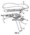
[Selection] Figure 2
Description
本発明は、人体支持構造物の分野での応用を見出すものであり、より詳しくは、請求項1の前文に述べるシート構造物に関する。 The present invention finds application in the field of human body support structures, and more particularly relates to a seat structure as described in the preamble of claim 1.
周知のように、自転車シートのデザインのための最重要要因は、使用者に対して最高の快適感を与える能力である。これは、適当なサドル詰め物を使用することによって実現できるが、さらにまた、着座位置を調節して、乗る人の体型およびその乗り方の好みにもっとも良く合うようにすることによっても実現できる。 As is well known, the most important factor for bicycle seat design is the ability to give the user maximum comfort. This can be achieved by using a suitable saddle padding, but also by adjusting the seating position to best fit the rider's body shape and preference for riding.
サドルをシート支柱に固定するのに現在使用できる手段は、剛性部材、一般にたとえば鋼または合金製の二つの金属棒から成り、これらの部材は、サドルの下部支持体に安定連結され、長さ方向に互いに適当な距離に配置される。これらの棒は、いろいろな連結手段、たとえば、ナットとねじのアセンブリによって固定されたプレートによって、サドルとシート支柱に固定することができる。 The currently available means for securing the saddle to the seat post consist of rigid members, typically two metal rods, for example made of steel or alloy, which are stably connected to the lower support of the saddle and are longitudinally Are arranged at an appropriate distance from each other. These rods can be secured to the saddle and seat post by various connecting means, for example, plates secured by nut and screw assemblies.
これらの先行技術の構成は、明らかな欠点を有し、それは、シート支柱のみに作用を及ぼすことによってしかサドルの高さ調節ができず、またサドルの長さ方向軸に沿ってサドルを適当な位置に配置できないということである。したがって、使用者は、体型に合わせた最適の乗り位置をとることができず、あるいは、たとえばそのような位置を変えて、たとえば下り坂で必要になるような、特定空力配置の機能が実現できるようにすることができない。 These prior art configurations have obvious drawbacks, which can only adjust the saddle height by acting only on the seat struts, and are suitable for adjusting the saddle along the longitudinal axis of the saddle. This means that it cannot be placed in a position. Therefore, the user cannot take the optimum riding position according to the body shape, or can change the position, for example, to realize the function of specific aerodynamic arrangement that is required on a downhill, for example. I can't do it.
前記欠点を除去するために、いくつかの構成が提案されており、そのような構成においては、実質的に機械的な手段を使用して、サドルの下部要素がシート支柱に固定される。前記手段は、自転車サドル下部の前記棒を、したがって該棒に固定された自転車サドルを、自転車サドルの長さ方向軸に沿って滑らせることを可能にする。 In order to eliminate the drawbacks, several arrangements have been proposed, in which the lower element of the saddle is secured to the seat post using substantially mechanical means. Said means makes it possible to slide the rod under the bicycle saddle and thus the bicycle saddle secured to the rod along the longitudinal axis of the bicycle saddle.
US-A-5,921,624号明細書に開示されているサドルアセンブリでは、サドルの下部支持体が、管状部材によってシート支柱に連結され、この管状部材は、二股になった後部を有し、三つの固定点でサドルの下部支持体に固定される。このレールは、適当な固定手段に連結され、該手段は、サドルの長さ方向の調節をも可能にするようになっているアセンブリ構成によって、シート支柱に固定されている。 In the saddle assembly disclosed in US-A-5,921,624, the lower support of the saddle is connected to the seat post by a tubular member, the tubular member having a bifurcated rear and three fixed Fixed to the saddle's lower support at points. The rail is connected to suitable fastening means, which are fastened to the seat post by an assembly configuration adapted to also allow for saddle length adjustment.
この構成は明らかな欠点を有しており、サドル位置の迅速かつ簡単な調節ができず、さらに、使用者は、特殊な工具たとえばねじ回しまたはレンチを使用して、不便な組み立ておよび分解作業を実行しなければならない。 This configuration has obvious disadvantages and does not allow quick and easy adjustment of the saddle position, and the user can use special tools such as screwdrivers or wrenches to perform inconvenient assembly and disassembly operations. Must be executed.
さらに、着脱できるようにサドル支持体に連結された管状部材は、使用時に支持体から外れることがある。 Furthermore, the tubular member connected to the saddle support so as to be detachable may be detached from the support in use.
また、支持体と管状部材との間に連結アセンブリを備えることは、明らかにサドル全体の大きさを増すものである。 Also, the provision of a coupling assembly between the support and the tubular member clearly increases the overall saddle size.
US-A-6,561,578号明細書の記載事項は請求項1の前文の基礎となるものであるが、該明細書に開示されている自転車サドルにおいては、単一の長さ方向レールによってシート支柱との連結が実現され、該レールは支持体と一体に成形され、適当な水平方向に作用する固定手段によってシート支柱に取りつけられている。 The description in US-A-6,561,578 is the basis of the preamble of claim 1, but in the bicycle saddle disclosed therein, the seat strut is separated by a single longitudinal rail. The rail is formed integrally with the support and is attached to the seat column by a fixing means acting in an appropriate horizontal direction.
この構成は、実用における安全性が不十分である。というのは、水平方向に作用する固定手段は、割合簡単にはずれる傾向があり、かなり長時間の使用後には特にそうである。 This configuration has insufficient safety in practical use. This is because the fixing means acting in the horizontal direction tend to be easily dislodged, especially after a fairly long period of use.
さらに、前記サドルは、明らかな欠点を有し、自転車に乗る人の重さを均一かつ有効に支持し、また分散させることができず、そのため、過剰な力が体の特定領域特に坐骨領域にかかることがある。 In addition, the saddle has obvious drawbacks and cannot even and effectively support and disperse the weight of the rider, so that excessive force can be applied to certain areas of the body, especially the ischial area. It may take.
さらに、自転車に乗る人の重さの不適当な分布により、連結アセンブリに損傷が生じることがあり、場合によっては破壊が起こりうる。 In addition, improper distribution of the weight of the cyclist can cause damage to the coupling assembly, and in some cases, destruction.
最後に、前記いくつかの構成の共通の欠点は、サドル−シート支柱アセンブリの高すぎる高さであり、これは使用者にとって、不快であり、非実用的である。この問題は、特に、シート支柱が、懸架シート支柱であって、懸架アセンブリが過剰な大きさを有する場合に、特に強く感じられる Finally, a common drawback of the several configurations is the saddle-seat post assembly being too high, which is uncomfortable and impractical for the user. This problem is particularly felt when the seat post is a suspended seat post and the suspension assembly has an excessive size.
本発明の目的は、能率的で割合に経済的な、長さ方向に調節可能なシート構造物を提供することによって、前記欠点を克服することである。 The object of the present invention is to overcome the aforementioned drawbacks by providing a sheet structure that is lengthwise adjustable, which is efficient and relatively economical.
本発明の主目的は、長時間の使用のあとでも、サドルの安定な長続きする配置を保証するシート構造物を提供することである。 The main object of the present invention is to provide a seat structure that guarantees a stable and lasting arrangement of the saddle even after prolonged use.
本発明のもう1つの目的は、最適の荷重分布を可能にする一方、シート位置の縦方向および/または角度および/または垂直方向の調節を可能にするシート構造物を提供することである。 Another object of the present invention is to provide a seat structure that allows for optimal load distribution while allowing longitudinal and / or angular and / or vertical adjustment of the seat position.
本発明のもう1つの目的は、外部工具の使用なしで、迅速な位置調節のできるシート構造物を提供することである。 Another object of the present invention is to provide a seat structure that can be quickly adjusted without the use of external tools.
もう1つの目的は、構造物全体にわたる使用者の体重の均一な分布を可能にするシート構造物を提供することである。 Another object is to provide a seat structure that allows a uniform distribution of the user's weight throughout the structure.
本発明のもう1つの目的は、可能な限り軽量かつ柔軟で、圧力に対する十分な抵抗を保証するシート構造物を提供することである。 Another object of the invention is to provide a seat structure that is as light and flexible as possible and ensures sufficient resistance to pressure.
最後に、本発明の目的は、支持部材および構造物から成るアセンブリの高さを最小限に抑えるような構成を有するシート構造物を提供することである。 Finally, it is an object of the present invention to provide a seat structure having a configuration that minimizes the height of the assembly of support members and structure.
前記およびその他の目的、ならびに以下でもっとはっきりするその他の目的は、請求項1に定義されているシート構造物によって満たされる。該構造物は、使用者の重量の少なくとも一部を支持することを意図する下面と上面とを有する支持要素と、前記支持要素に付随する固定手段であって、前記支持要素を自転車または人体支持フレームに、長さ方向および/または角度および/または垂直方向に関して位置調節可能なように固定する固定手段と、から成る。このシート構造物は、前記固定手段が、少なくとも1つの長さ方向延長部を有し、該延長部が、前記支持要素から下方に延びていて、かつ少なくとも1つの実質的に水平な部分を有し、該部分が、前記フレームに付随し、実質的に垂直方向に作用する少なくとも1つの実質的に水平のクランプ部材によって、クランプされるようになっていることを特徴とする。 These and other objects, as well as other objects that will become clearer below, are met by a sheet structure as defined in claim 1. The structure comprises a support element having a lower surface and an upper surface intended to support at least a portion of a user's weight, and a fixing means associated with the support element, the support element supporting a bicycle or a human body And fixing means for fixing the frame so as to be adjustable with respect to the length direction and / or the angle and / or the vertical direction. In this seat structure, the fastening means has at least one longitudinal extension, the extension extending downward from the support element and having at least one substantially horizontal portion. The portion is adapted to be clamped by at least one substantially horizontal clamping member attached to the frame and acting in a substantially vertical direction.
この特定実施形態により、本発明のシート構造物は、何時間もの使用のあとでも高度に安全な荷重支持フレームへの固定を与える。 With this particular embodiment, the seat structure of the present invention provides a highly secure anchorage to the load bearing frame after hours of use.
さらに、この構造物は、外部工具の使用なしで、長さ方向および角度の簡単かつ迅速な調節が可能である。 Furthermore, this structure allows simple and quick adjustment of the length and angle without the use of external tools.
好ましくは、前記延長部は、この構造物の支持要素と一体に作ることができる。そうすれば、構造物全体が非常に強く、破壊の危険が最小限に押えられる。 Preferably, the extension can be made in one piece with the support element of the structure. In this way, the entire structure is very strong and the risk of destruction is minimized.
本発明の好ましい非排他的実施形態においては、一対の延長部を備えることができ、これらの延長部は、支持要素と一体で、好ましくは平行で横方向に間隔をとって配置される。これらの延長部は、垂直に配向され、また、それぞれ外側に延びた水平部分を備えている。 In a preferred non-exclusive embodiment of the invention, a pair of extensions can be provided, these extensions being integral with the support element, preferably parallel and spaced laterally. These extensions are oriented vertically and each have a horizontal portion extending outwardly.
この実施形態により、荷重が実質的に支持要素全体に均一に分布するシート構造物が提供される。 This embodiment provides a sheet structure in which the load is distributed substantially uniformly throughout the support element.
好ましくは、前記水平部分は、所定角度だけ傾斜したそれぞれの上面を有することができる。さらに、これらの水平部分は拡大された上部へりを有することができ、これらのへりは好ましくは、平行で同一平面上にある。 Preferably, the horizontal portion may have respective upper surfaces inclined by a predetermined angle. Furthermore, these horizontal portions can have enlarged upper edges, which are preferably parallel and coplanar.
ここで、水平部分は、フレームクランプ手段のためのそれぞれの長さ方向の受容部を定める。したがって、実質的に垂直な方向の連結動作(vincularreaction)が得られ、そのため、構造物と該構造物に連結されるフレームとの高度に安定した連結が可能になる。 Here, the horizontal portion defines a respective longitudinal receptacle for the frame clamping means. Thus, a substantially vertical direction of vincularreaction is obtained, thus allowing a highly stable connection between the structure and the frame connected to the structure.
本発明の重要な特徴によれば、延長部は実質的に長さ方向の溝を定めることができ、この溝は、フレームクランプ手段の間に配置されるスペーサー部材を滑動自在に案内する。 According to an important feature of the invention, the extension can define a substantially longitudinal groove, which slidably guides the spacer member arranged between the frame clamping means.
この特徴により、本発明の構造物は、その底部でさらなる支持力を有することができ、フレームとの連結の安定性がかなり増大する。 This feature allows the structure of the present invention to have additional support at its bottom, greatly increasing the stability of the connection with the frame.
さらに、構造物のこの構成により、構造物と支持アセンブリの高さを最小限に抑えることができる。 Furthermore, this configuration of the structure allows the height of the structure and the support assembly to be minimized.
本発明のさらなる特徴と利点とは、添付の図面に即してなされる、本発明によるシート構造物の好ましい非排他的な実施形態の詳しい説明からさらにはっきりするであろう。ここに示す例は、本発明を限定するものではない。 Further features and advantages of the present invention will become more apparent from the detailed description of the preferred non-exclusive embodiments of the seat structure according to the present invention, made with reference to the accompanying drawings. The examples shown here are not intended to limit the invention.
本発明のシート構造物は、人体の尻を支持することができ、この構造物は、添付の図面に示すように、自動車シート、椅子、または自転車サドルとして構成することができる。 The seat structure of the present invention can support the buttocks of a human body, and the structure can be configured as an automobile seat, chair, or bicycle saddle, as shown in the accompanying drawings.
番号1で全体を示すシート構造物は、下面4と上面3を有する支持要素2を有し、後者は使用者の重さを支持することを意図する。固定手段5も備えられ、これは、支持要素2に固定され、該要素を自転車フレームTに連結するためのものである。代表的実施形態においては、弾性詰め物11が備えられ、これは、フォーム、スポンジ、エラストマー材料、ゲル、その他で作られ、要素2を覆うように配置される。
The sheet structure, indicated generally by the number 1, has a
本発明の好ましい非排他的実施形態においては、固定手段5は、横方向に間隔をとって配置された一対の延長部6、6´を備えており、これらの延長部は、それぞれ水平部分7、7´を備えている。
In a preferred non-exclusive embodiment of the invention, the fixing means 5 comprises a pair of
延長部6、6´は、実質的に垂直かつ平行であり、部分7、7´は、フレームTをクランプするための部材Sへの固定のために外側に延びている。フレームTは、図3に示すように、軸Xに沿って、実質的に水平な方向に延びている。
The
したがって、水平部分7、7´とクランプ部材Sとの間で連結関係にある部分は、軸Yに沿って、実質的に垂直な方向に延びている。
Therefore, the portion that is connected between the
フレームTをクランプするための手段Sに対する構造物の長さ方向位置の簡単な調節のために、部分7、7´は、実質的に一定の断面を有し、この断面は、それぞれの延長部6、6´の実質的に全体に沿って延びている。
For a simple adjustment of the longitudinal position of the structure relative to the means S for clamping the frame T, the
図3および4に示すように、本発明の非排他的特定実施形態においては、支持要素2は、フレームTへの固定のための手段5とは独立に作られており、これらの間に間隙iが備えられている。そのような間隙は、場合によっては、任意の衝撃吸収手段M、たとえば普通のばねタイプの緩衝器またはエラストマー部材を有することもできる。
As shown in FIGS. 3 and 4, in a non-exclusive specific embodiment of the invention, the
また、このシート構造物は、その前部Aで延長され、後部Pで拡幅されているように、構成され、特に自転車サドルの場合におけるように、使用者の着座姿勢にもっとも良く合うようにされる。 Also, the seat structure is configured to be extended at its front part A and widened at its rear part P, and is best adapted to the user's sitting posture, especially in the case of a bicycle saddle. The
好ましくは、支持要素2および固定手段5は、剛性または半剛性材料、すなわち強化金属またはポリマー材料、たとえばガラスファイバー強化ポリアミド66で作られる。いくつかの方法たとえば成形を使用して、これらを作ることができる。要素2および固定手段5は、必ずしも同じ材料で作る必要はない。
Preferably, the
延長部6、6´は、通常の固定手段たとえばねじまたはリベットで支持要素2に連結することができるが、好ましくは、要素2と一体に成形する。
The
固定手段5は、それぞれ前部A、A´において、支持要素2に連結される。
The fixing means 5 are connected to the
水平部分7、7´がそれぞれ、所定の角度αだけ傾斜した上面8、8´を有するのが便利である。この角度は、両面8、8´で必ずしも同じでなくても良い。
Conveniently, the
好ましくは、これらの面は、安全なクランプを保証する平行な拡大された上部へり9、9´を有する。 Preferably, these surfaces have parallel enlarged upper edges 9, 9 'that ensure a safe clamp.
このようにして、適当な受容部が、フレームTをクランプするための手段Sに対して定められる。この受容部は、たとえば、各延長部6、6´の水平部分7、7´に相補的に嵌めあわされるようになっている二つの実質的に長さ方向に延びた部材B、B´とすることができ、またこの受容部は該受容部に連結された二つのレバーL、L´によってクランプすることができる。
In this way, a suitable receiving part is defined for the means S for clamping the frame T. This receiving part is, for example, two substantially longitudinally extending members B, B ′ adapted to be fitted complementarily to the
延長部6、6´と部分7、7´とによって形成されるアセンブリは、実質的に長さ方向の溝を定め、この溝は、フレームTたとえばシート支柱の端部のクランプのための部材Sの間に配置された適当なスペーサー部材Cを滑動自在に案内する。
The assembly formed by the
以上のように、本発明のシート構造物は、意図した目的を満たすものであり、特に、何時間もの使用のあとでも、サドルの安定な長続きする配置を保証する目的を満たすものである。 As described above, the sheet structure of the present invention satisfies the intended purpose, and particularly satisfies the purpose of guaranteeing a stable and long-lasting arrangement of the saddle even after many hours of use.
実質的に垂直方向に作用する水平クランプ部材Sによって固定されるようになっている水平部分7が備わっていることにより、連結関係にある部分は、軸Yに沿って、同じ方向に延びており、したがって高度に安定で長続きする固定が得られる。
Due to the provision of a
本発明の構造物には、特許請求の範囲に示す発明概念の範囲内で、多くの変更と変形とを加えることができる。本発明の範囲を逸脱することなく、個々の部品はすべて、技術的に同等の他の部品で置き換えることができ、材料は、いろいろな必要に応じて変えることができる。 Many changes and modifications can be made to the structure of the present invention within the scope of the inventive concept shown in the claims. All individual parts can be replaced with other technically equivalent parts without departing from the scope of the invention, and the materials can be varied according to various needs.
以上、添付の図面を参照することによって、本発明のシート構造物を説明したが、明細書と特許請求の範囲で使用した参照番号は、本発明のより良い理解のためにだけ使用したものであり、いかなる意味でも特許請求の範囲の制限を意図するものではない。 Although the seat structure of the present invention has been described with reference to the accompanying drawings, the reference numerals used in the specification and claims are used only for a better understanding of the present invention. There is no intention to limit the scope of the claims in any way.
1 シート構造物
2 支持要素
3 上面
4 下面
5 固定手段
6 延長部
6´ 延長部
7 水平部分
7´ 水平部分
8 上面
8´ 上面
9 上部へり
9´ 上部へり
10 長さ方向の溝
11 弾性詰め物
A 前部
A´ 前部
B 長さ方向に延びた部材
B´ 長さ方向に延びた部材
C スペーサー部材
L レバー
L´ レバー
M 衝撃吸収手段
P 後部
S Tをクランプするための部材
T 自転車フレーム
X 軸
Y 軸
i 間隙
α 角度
1 Seat structure
2 Support elements
3 Top view
4 Bottom
5 Fixing means
6 Extension
6´ extension
7 Horizontal part
7´ horizontal part
8 Top view
8´ top surface
9 Upper edge
9´ upper edge
10 Longitudinal groove
11 Elastic padding
A front
A´ front
B Longitudinal member
B´ Longitudinal member
C Spacer member
L lever
L´ lever
M Shock absorption means
P rear
Member for clamping ST
T bicycle frame
X axis
Y axis
i gap α angle
Claims (11)
- 使用者の重量の少なくとも一部を支持することを意図する下面(4)と上面(3)とを有する支持要素(2)、
- 前記支持要素(2)に付随する固定手段(5)であって、前記支持要素(2)を自転車または人体支持フレーム(T)に、長さ方向および/または角度および/または垂直方向に関して位置調節可能なように固定する固定手段(5)、
から成るシート構造物において、
前記固定手段(5)が、少なくとも1つの長さ方向延長部(6)を有し、該延長部が、前記支持要素(2)から下方に延びていて、かつ少なくとも1つの実質的に水平な部分(7)を有し、該部分が、前記フレーム(T)に付随し、実質的に垂直方向に作用する少なくとも1つの実質的に水平のクランプ部材(S)によって、クランプされるようになっている、
ことを特徴とするシート構造物。 A seat structure, in particular for a bicycle and a human body support frame,
-A support element (2) having a lower surface (4) and an upper surface (3) intended to support at least part of the weight of the user,
Fixing means (5) associated with the support element (2), wherein the support element (2) is positioned on a bicycle or a human body support frame (T) with respect to the length direction and / or angle and / or vertical Fixing means (5) for fixing in an adjustable manner,
In a sheet structure consisting of
Said securing means (5) has at least one longitudinal extension (6), said extension extending downward from said support element (2) and at least one substantially horizontal Having a portion (7), said portion being associated with said frame (T) and being clamped by at least one substantially horizontal clamping member (S) acting in a substantially vertical direction ing,
A sheet structure characterized by that.
Applications Claiming Priority (2)
| Application Number | Priority Date | Filing Date | Title |
|---|---|---|---|
| IT000128A ITVI20050128A1 (en) | 2005-04-29 | 2005-04-29 | SEAT STRUCTURE, PARTICULARLY FOR CYCLE FRAMES AND FOR THE SUPPORT OF THE HUMAN BODY |
| PCT/IB2006/051344 WO2006117742A1 (en) | 2005-04-29 | 2006-04-28 | Seat structure, particularly for cycle and human body support frames |
Publications (2)
| Publication Number | Publication Date |
|---|---|
| JP2008539126A true JP2008539126A (en) | 2008-11-13 |
| JP2008539126A5 JP2008539126A5 (en) | 2009-06-18 |
Family
ID=36688145
Family Applications (1)
| Application Number | Title | Priority Date | Filing Date |
|---|---|---|---|
| JP2008508403A Pending JP2008539126A (en) | 2005-04-29 | 2006-04-28 | Seat structure, especially for bicycles and human body support frames |
Country Status (8)
| Country | Link |
|---|---|
| US (1) | US7775588B2 (en) |
| EP (1) | EP1883572A1 (en) |
| JP (1) | JP2008539126A (en) |
| CN (1) | CN100584685C (en) |
| BR (1) | BRPI0613205A2 (en) |
| IT (1) | ITVI20050128A1 (en) |
| TW (1) | TW200637757A (en) |
| WO (1) | WO2006117742A1 (en) |
Cited By (1)
| Publication number | Priority date | Publication date | Assignee | Title |
|---|---|---|---|---|
| JP2017533852A (en) * | 2014-06-16 | 2017-11-16 | イノ ビジョン リミテッド | Bicycle seat and lock assembly |
Families Citing this family (7)
| Publication number | Priority date | Publication date | Assignee | Title |
|---|---|---|---|---|
| TWM407875U (en) * | 2010-12-24 | 2011-07-21 | Jet Sport Ind Co Ltd | Seat paddle adjustment set |
| SK6148Y1 (en) | 2011-08-22 | 2012-06-04 | Boris Hudak | Bike with modifiable design to climb, descent and terrain roughness |
| US9481420B2 (en) | 2013-08-01 | 2016-11-01 | Specialized Bicycle Components, Inc. | Saddle adjustment system |
| EP3233616B1 (en) | 2014-12-18 | 2020-05-27 | Specialized Bicycle Components, Inc. | Saddle adjustment system |
| US9616954B2 (en) | 2014-12-18 | 2017-04-11 | Specialized Bicycle Components, Inc. | Saddle adjustment system |
| US10717485B2 (en) * | 2015-12-28 | 2020-07-21 | Joshua C. Hight | Bicycle saddle quick release |
| US11602665B2 (en) * | 2020-09-06 | 2023-03-14 | Peloton Interactive, Inc. | Seat assembly system and methods |
Citations (6)
| Publication number | Priority date | Publication date | Assignee | Title |
|---|---|---|---|---|
| JPH08239071A (en) * | 1995-03-03 | 1996-09-17 | Yamaha Motor Co Ltd | Rotator of bicycle seat |
| JPH08253181A (en) * | 1995-03-20 | 1996-10-01 | Yamaha Motor Co Ltd | Rotary device of bicycle seat |
| JPH08310463A (en) * | 1995-05-17 | 1996-11-26 | Kanto Auto Works Ltd | Locking mechanism of saddle for collapsible bicycle |
| JP2001106137A (en) * | 1999-10-13 | 2001-04-17 | Honda Motor Co Ltd | Bicycle seat rotating device |
| JP2003048580A (en) * | 2001-08-06 | 2003-02-18 | Matsushita Electric Ind Co Ltd | Bicycle with antitheft device |
| JP2004330815A (en) * | 2003-04-30 | 2004-11-25 | Marui:Kk | Mounting structure for bicycle saddle |
Family Cites Families (12)
| Publication number | Priority date | Publication date | Assignee | Title |
|---|---|---|---|---|
| FR877909A (en) * | 1941-12-19 | 1943-01-06 | Lightweight saddle with simplified attachment | |
| US2575496A (en) * | 1949-01-29 | 1951-11-20 | Goodrich Co B F | Seat suspension |
| US4108462A (en) * | 1977-02-11 | 1978-08-22 | Martin Lee D | Bicycle seat and mounting therefor |
| IT222105Z2 (en) * | 1991-12-13 | 1994-12-30 | Selle Italia Srl | SAFETY SADDLE STRUCTURE FOR MOTORCYCLES OR SIMILAR BICYCLES |
| CN2112563U (en) * | 1991-12-25 | 1992-08-12 | 萧景佳 | Shock-proof saddle of bicycle |
| CN2202698Y (en) * | 1993-12-16 | 1995-07-05 | 张昆华 | Adjustable and flexible support for bicycle saddle |
| US5536065A (en) * | 1994-03-01 | 1996-07-16 | Selle San Marco Di Girardi Comm. Luigi S.P.A. | Saddle for a bicycle capable of hooking directly to the sleeve which supports the saddle |
| AU5061599A (en) * | 1998-07-16 | 2000-02-07 | Andries Gaastra | Cycle, in particular a bicycle |
| ITMI20010073A1 (en) * | 2001-01-16 | 2002-07-16 | Selle Italia Srl | STRUCTURE OF SELLA PERFECTED PARTICOLARMNETE STUDY FOR CYCLES AND MOTORCYCLES |
| US6561578B1 (en) * | 2001-03-30 | 2003-05-13 | Jerome Mel | Seat for bicycles |
| US6769736B2 (en) | 2001-11-13 | 2004-08-03 | Earthlite Massage Tables, Inc. | Positioning mechanism for a massage chair |
| ITVI20050088A1 (en) * | 2005-03-24 | 2006-09-26 | Selle Royal Spa | INTEGRATED SUPPORT STRUCTURE FOR THE HUMAN BODY, PARTICULARLY A SADDLE OR SEAT FOR A VEHICLE |
-
2005
- 2005-04-29 IT IT000128A patent/ITVI20050128A1/en unknown
-
2006
- 2006-04-14 TW TW095113337A patent/TW200637757A/en unknown
- 2006-04-28 CN CN200680014563A patent/CN100584685C/en active Active
- 2006-04-28 EP EP06728086A patent/EP1883572A1/en not_active Withdrawn
- 2006-04-28 JP JP2008508403A patent/JP2008539126A/en active Pending
- 2006-04-28 US US11/912,892 patent/US7775588B2/en active Active
- 2006-04-28 WO PCT/IB2006/051344 patent/WO2006117742A1/en not_active Application Discontinuation
- 2006-04-28 BR BRPI0613205-7A patent/BRPI0613205A2/en not_active IP Right Cessation
Patent Citations (6)
| Publication number | Priority date | Publication date | Assignee | Title |
|---|---|---|---|---|
| JPH08239071A (en) * | 1995-03-03 | 1996-09-17 | Yamaha Motor Co Ltd | Rotator of bicycle seat |
| JPH08253181A (en) * | 1995-03-20 | 1996-10-01 | Yamaha Motor Co Ltd | Rotary device of bicycle seat |
| JPH08310463A (en) * | 1995-05-17 | 1996-11-26 | Kanto Auto Works Ltd | Locking mechanism of saddle for collapsible bicycle |
| JP2001106137A (en) * | 1999-10-13 | 2001-04-17 | Honda Motor Co Ltd | Bicycle seat rotating device |
| JP2003048580A (en) * | 2001-08-06 | 2003-02-18 | Matsushita Electric Ind Co Ltd | Bicycle with antitheft device |
| JP2004330815A (en) * | 2003-04-30 | 2004-11-25 | Marui:Kk | Mounting structure for bicycle saddle |
Cited By (2)
| Publication number | Priority date | Publication date | Assignee | Title |
|---|---|---|---|---|
| JP2017533852A (en) * | 2014-06-16 | 2017-11-16 | イノ ビジョン リミテッド | Bicycle seat and lock assembly |
| US10392065B2 (en) | 2014-06-16 | 2019-08-27 | Ino Vision Ltd. | Bicycle seat and lock assembly |
Also Published As
| Publication number | Publication date |
|---|---|
| CN100584685C (en) | 2010-01-27 |
| EP1883572A1 (en) | 2008-02-06 |
| CN101166660A (en) | 2008-04-23 |
| ITVI20050128A1 (en) | 2006-10-30 |
| US7775588B2 (en) | 2010-08-17 |
| US20090127898A1 (en) | 2009-05-21 |
| WO2006117742A1 (en) | 2006-11-09 |
| TW200637757A (en) | 2006-11-01 |
| BRPI0613205A2 (en) | 2010-12-28 |
Similar Documents
| Publication | Publication Date | Title |
|---|---|---|
| JP2008539126A (en) | Seat structure, especially for bicycles and human body support frames | |
| EP2480445B1 (en) | Ventilated saddle | |
| US7635162B2 (en) | Bicycle seat | |
| US7121622B1 (en) | Suspension bicycle seat | |
| JP5005167B2 (en) | Chair backrest structure | |
| JP3136741U (en) | Bicycle saddle assembly | |
| US20040004375A1 (en) | Bicycle saddle | |
| US7753388B2 (en) | Front wheel drive recumbent bicycle | |
| US8864159B2 (en) | Bicycle frame | |
| US4363516A (en) | Thrust support for bicycle seats | |
| US7549698B2 (en) | Integrated human body support structure, particularly a saddle or seat for a vehicle | |
| US20080265635A1 (en) | Bicycle Saddle | |
| JP2008539126A5 (en) | ||
| US7552967B2 (en) | Base for a bicycle saddle | |
| US5297846A (en) | Pivoting bicycle seat assembly | |
| US20110115265A1 (en) | Bicycle Saddle | |
| US6755464B2 (en) | Bicycle seat | |
| KR101916656B1 (en) | Bicycle saddle shock absorber | |
| JP2009517285A (en) | Mounting assembly for stable mounting of seats, especially bicycle saddles | |
| EP1982907B1 (en) | Frame for a bicycle saddle | |
| KR102332986B1 (en) | Moving Device Saddle with Pelvic Support | |
| CN109562803B (en) | Bicycle seat and bicycle | |
| NL2033110B1 (en) | Additional seat structure for electric bicycles | |
| EP0832810A1 (en) | "Support and connection device for bicycle baby-seats" | |
| CN210618318U (en) | Bicycle seat |
Legal Events
| Date | Code | Title | Description |
|---|---|---|---|
| A521 | Written amendment |
Free format text: JAPANESE INTERMEDIATE CODE: A523 Effective date: 20090424 |
|
| A621 | Written request for application examination |
Free format text: JAPANESE INTERMEDIATE CODE: A621 Effective date: 20090424 |
|
| A131 | Notification of reasons for refusal |
Free format text: JAPANESE INTERMEDIATE CODE: A131 Effective date: 20110719 |
|
| A02 | Decision of refusal |
Free format text: JAPANESE INTERMEDIATE CODE: A02 Effective date: 20111220 |