JP2008534222A - Non-circular ball and method - Google Patents
Non-circular ball and method Download PDFInfo
- Publication number
- JP2008534222A JP2008534222A JP2008505428A JP2008505428A JP2008534222A JP 2008534222 A JP2008534222 A JP 2008534222A JP 2008505428 A JP2008505428 A JP 2008505428A JP 2008505428 A JP2008505428 A JP 2008505428A JP 2008534222 A JP2008534222 A JP 2008534222A
- Authority
- JP
- Japan
- Prior art keywords
- section
- spacer
- spherical
- vertebral
- rotation mechanism
- Prior art date
- Legal status (The legal status is an assumption and is not a legal conclusion. Google has not performed a legal analysis and makes no representation as to the accuracy of the status listed.)
- Pending
Links
Images


Classifications
-
- A—HUMAN NECESSITIES
- A61—MEDICAL OR VETERINARY SCIENCE; HYGIENE
- A61F—FILTERS IMPLANTABLE INTO BLOOD VESSELS; PROSTHESES; DEVICES PROVIDING PATENCY TO, OR PREVENTING COLLAPSING OF, TUBULAR STRUCTURES OF THE BODY, e.g. STENTS; ORTHOPAEDIC, NURSING OR CONTRACEPTIVE DEVICES; FOMENTATION; TREATMENT OR PROTECTION OF EYES OR EARS; BANDAGES, DRESSINGS OR ABSORBENT PADS; FIRST-AID KITS
- A61F2/00—Filters implantable into blood vessels; Prostheses, i.e. artificial substitutes or replacements for parts of the body; Appliances for connecting them with the body; Devices providing patency to, or preventing collapsing of, tubular structures of the body, e.g. stents
- A61F2/02—Prostheses implantable into the body
- A61F2/30—Joints
- A61F2/46—Special tools or methods for implanting or extracting artificial joints, accessories, bone grafts or substitutes, or particular adaptations therefor
- A61F2/4603—Special tools or methods for implanting or extracting artificial joints, accessories, bone grafts or substitutes, or particular adaptations therefor for insertion or extraction of endoprosthetic joints or of accessories thereof
- A61F2/4611—Special tools or methods for implanting or extracting artificial joints, accessories, bone grafts or substitutes, or particular adaptations therefor for insertion or extraction of endoprosthetic joints or of accessories thereof of spinal prostheses
-
- A—HUMAN NECESSITIES
- A61—MEDICAL OR VETERINARY SCIENCE; HYGIENE
- A61F—FILTERS IMPLANTABLE INTO BLOOD VESSELS; PROSTHESES; DEVICES PROVIDING PATENCY TO, OR PREVENTING COLLAPSING OF, TUBULAR STRUCTURES OF THE BODY, e.g. STENTS; ORTHOPAEDIC, NURSING OR CONTRACEPTIVE DEVICES; FOMENTATION; TREATMENT OR PROTECTION OF EYES OR EARS; BANDAGES, DRESSINGS OR ABSORBENT PADS; FIRST-AID KITS
- A61F2/00—Filters implantable into blood vessels; Prostheses, i.e. artificial substitutes or replacements for parts of the body; Appliances for connecting them with the body; Devices providing patency to, or preventing collapsing of, tubular structures of the body, e.g. stents
- A61F2/02—Prostheses implantable into the body
- A61F2/30—Joints
- A61F2/44—Joints for the spine, e.g. vertebrae, spinal discs
- A61F2/442—Intervertebral or spinal discs, e.g. resilient
-
- A—HUMAN NECESSITIES
- A61—MEDICAL OR VETERINARY SCIENCE; HYGIENE
- A61F—FILTERS IMPLANTABLE INTO BLOOD VESSELS; PROSTHESES; DEVICES PROVIDING PATENCY TO, OR PREVENTING COLLAPSING OF, TUBULAR STRUCTURES OF THE BODY, e.g. STENTS; ORTHOPAEDIC, NURSING OR CONTRACEPTIVE DEVICES; FOMENTATION; TREATMENT OR PROTECTION OF EYES OR EARS; BANDAGES, DRESSINGS OR ABSORBENT PADS; FIRST-AID KITS
- A61F2/00—Filters implantable into blood vessels; Prostheses, i.e. artificial substitutes or replacements for parts of the body; Appliances for connecting them with the body; Devices providing patency to, or preventing collapsing of, tubular structures of the body, e.g. stents
- A61F2/02—Prostheses implantable into the body
- A61F2/30—Joints
- A61F2/30721—Accessories
- A61F2/30728—Collars; Bone edge protectors
-
- A—HUMAN NECESSITIES
- A61—MEDICAL OR VETERINARY SCIENCE; HYGIENE
- A61F—FILTERS IMPLANTABLE INTO BLOOD VESSELS; PROSTHESES; DEVICES PROVIDING PATENCY TO, OR PREVENTING COLLAPSING OF, TUBULAR STRUCTURES OF THE BODY, e.g. STENTS; ORTHOPAEDIC, NURSING OR CONTRACEPTIVE DEVICES; FOMENTATION; TREATMENT OR PROTECTION OF EYES OR EARS; BANDAGES, DRESSINGS OR ABSORBENT PADS; FIRST-AID KITS
- A61F2/00—Filters implantable into blood vessels; Prostheses, i.e. artificial substitutes or replacements for parts of the body; Appliances for connecting them with the body; Devices providing patency to, or preventing collapsing of, tubular structures of the body, e.g. stents
- A61F2/02—Prostheses implantable into the body
- A61F2/30—Joints
- A61F2002/30001—Additional features of subject-matter classified in A61F2/28, A61F2/30 and subgroups thereof
- A61F2002/30108—Shapes
- A61F2002/30199—Three-dimensional shapes
- A61F2002/30242—Three-dimensional shapes spherical
-
- A—HUMAN NECESSITIES
- A61—MEDICAL OR VETERINARY SCIENCE; HYGIENE
- A61F—FILTERS IMPLANTABLE INTO BLOOD VESSELS; PROSTHESES; DEVICES PROVIDING PATENCY TO, OR PREVENTING COLLAPSING OF, TUBULAR STRUCTURES OF THE BODY, e.g. STENTS; ORTHOPAEDIC, NURSING OR CONTRACEPTIVE DEVICES; FOMENTATION; TREATMENT OR PROTECTION OF EYES OR EARS; BANDAGES, DRESSINGS OR ABSORBENT PADS; FIRST-AID KITS
- A61F2/00—Filters implantable into blood vessels; Prostheses, i.e. artificial substitutes or replacements for parts of the body; Appliances for connecting them with the body; Devices providing patency to, or preventing collapsing of, tubular structures of the body, e.g. stents
- A61F2/02—Prostheses implantable into the body
- A61F2/30—Joints
- A61F2002/30001—Additional features of subject-matter classified in A61F2/28, A61F2/30 and subgroups thereof
- A61F2002/30316—The prosthesis having different structural features at different locations within the same prosthesis; Connections between prosthetic parts; Special structural features of bone or joint prostheses not otherwise provided for
- A61F2002/30329—Connections or couplings between prosthetic parts, e.g. between modular parts; Connecting elements
- A61F2002/30331—Connections or couplings between prosthetic parts, e.g. between modular parts; Connecting elements made by longitudinally pushing a protrusion into a complementarily-shaped recess, e.g. held by friction fit
- A61F2002/30332—Conically- or frustoconically-shaped protrusion and recess
-
- A—HUMAN NECESSITIES
- A61—MEDICAL OR VETERINARY SCIENCE; HYGIENE
- A61F—FILTERS IMPLANTABLE INTO BLOOD VESSELS; PROSTHESES; DEVICES PROVIDING PATENCY TO, OR PREVENTING COLLAPSING OF, TUBULAR STRUCTURES OF THE BODY, e.g. STENTS; ORTHOPAEDIC, NURSING OR CONTRACEPTIVE DEVICES; FOMENTATION; TREATMENT OR PROTECTION OF EYES OR EARS; BANDAGES, DRESSINGS OR ABSORBENT PADS; FIRST-AID KITS
- A61F2/00—Filters implantable into blood vessels; Prostheses, i.e. artificial substitutes or replacements for parts of the body; Appliances for connecting them with the body; Devices providing patency to, or preventing collapsing of, tubular structures of the body, e.g. stents
- A61F2/02—Prostheses implantable into the body
- A61F2/30—Joints
- A61F2002/30001—Additional features of subject-matter classified in A61F2/28, A61F2/30 and subgroups thereof
- A61F2002/30316—The prosthesis having different structural features at different locations within the same prosthesis; Connections between prosthetic parts; Special structural features of bone or joint prostheses not otherwise provided for
- A61F2002/30329—Connections or couplings between prosthetic parts, e.g. between modular parts; Connecting elements
- A61F2002/30476—Connections or couplings between prosthetic parts, e.g. between modular parts; Connecting elements locked by an additional locking mechanism
- A61F2002/30487—Circumferential cooperating grooves and beads on cooperating lateral surfaces of a mainly longitudinal connection
-
- A—HUMAN NECESSITIES
- A61—MEDICAL OR VETERINARY SCIENCE; HYGIENE
- A61F—FILTERS IMPLANTABLE INTO BLOOD VESSELS; PROSTHESES; DEVICES PROVIDING PATENCY TO, OR PREVENTING COLLAPSING OF, TUBULAR STRUCTURES OF THE BODY, e.g. STENTS; ORTHOPAEDIC, NURSING OR CONTRACEPTIVE DEVICES; FOMENTATION; TREATMENT OR PROTECTION OF EYES OR EARS; BANDAGES, DRESSINGS OR ABSORBENT PADS; FIRST-AID KITS
- A61F2/00—Filters implantable into blood vessels; Prostheses, i.e. artificial substitutes or replacements for parts of the body; Appliances for connecting them with the body; Devices providing patency to, or preventing collapsing of, tubular structures of the body, e.g. stents
- A61F2/02—Prostheses implantable into the body
- A61F2/30—Joints
- A61F2002/30001—Additional features of subject-matter classified in A61F2/28, A61F2/30 and subgroups thereof
- A61F2002/30316—The prosthesis having different structural features at different locations within the same prosthesis; Connections between prosthetic parts; Special structural features of bone or joint prostheses not otherwise provided for
- A61F2002/30535—Special structural features of bone or joint prostheses not otherwise provided for
- A61F2002/30593—Special structural features of bone or joint prostheses not otherwise provided for hollow
-
- A—HUMAN NECESSITIES
- A61—MEDICAL OR VETERINARY SCIENCE; HYGIENE
- A61F—FILTERS IMPLANTABLE INTO BLOOD VESSELS; PROSTHESES; DEVICES PROVIDING PATENCY TO, OR PREVENTING COLLAPSING OF, TUBULAR STRUCTURES OF THE BODY, e.g. STENTS; ORTHOPAEDIC, NURSING OR CONTRACEPTIVE DEVICES; FOMENTATION; TREATMENT OR PROTECTION OF EYES OR EARS; BANDAGES, DRESSINGS OR ABSORBENT PADS; FIRST-AID KITS
- A61F2/00—Filters implantable into blood vessels; Prostheses, i.e. artificial substitutes or replacements for parts of the body; Appliances for connecting them with the body; Devices providing patency to, or preventing collapsing of, tubular structures of the body, e.g. stents
- A61F2/02—Prostheses implantable into the body
- A61F2/30—Joints
- A61F2002/30001—Additional features of subject-matter classified in A61F2/28, A61F2/30 and subgroups thereof
- A61F2002/30316—The prosthesis having different structural features at different locations within the same prosthesis; Connections between prosthetic parts; Special structural features of bone or joint prostheses not otherwise provided for
- A61F2002/30535—Special structural features of bone or joint prostheses not otherwise provided for
- A61F2002/30601—Special structural features of bone or joint prostheses not otherwise provided for telescopic
-
- A—HUMAN NECESSITIES
- A61—MEDICAL OR VETERINARY SCIENCE; HYGIENE
- A61F—FILTERS IMPLANTABLE INTO BLOOD VESSELS; PROSTHESES; DEVICES PROVIDING PATENCY TO, OR PREVENTING COLLAPSING OF, TUBULAR STRUCTURES OF THE BODY, e.g. STENTS; ORTHOPAEDIC, NURSING OR CONTRACEPTIVE DEVICES; FOMENTATION; TREATMENT OR PROTECTION OF EYES OR EARS; BANDAGES, DRESSINGS OR ABSORBENT PADS; FIRST-AID KITS
- A61F2/00—Filters implantable into blood vessels; Prostheses, i.e. artificial substitutes or replacements for parts of the body; Appliances for connecting them with the body; Devices providing patency to, or preventing collapsing of, tubular structures of the body, e.g. stents
- A61F2/02—Prostheses implantable into the body
- A61F2/30—Joints
- A61F2002/30001—Additional features of subject-matter classified in A61F2/28, A61F2/30 and subgroups thereof
- A61F2002/30621—Features concerning the anatomical functioning or articulation of the prosthetic joint
- A61F2002/30649—Ball-and-socket joints
- A61F2002/30662—Ball-and-socket joints with rotation-limiting means
-
- A—HUMAN NECESSITIES
- A61—MEDICAL OR VETERINARY SCIENCE; HYGIENE
- A61F—FILTERS IMPLANTABLE INTO BLOOD VESSELS; PROSTHESES; DEVICES PROVIDING PATENCY TO, OR PREVENTING COLLAPSING OF, TUBULAR STRUCTURES OF THE BODY, e.g. STENTS; ORTHOPAEDIC, NURSING OR CONTRACEPTIVE DEVICES; FOMENTATION; TREATMENT OR PROTECTION OF EYES OR EARS; BANDAGES, DRESSINGS OR ABSORBENT PADS; FIRST-AID KITS
- A61F2/00—Filters implantable into blood vessels; Prostheses, i.e. artificial substitutes or replacements for parts of the body; Appliances for connecting them with the body; Devices providing patency to, or preventing collapsing of, tubular structures of the body, e.g. stents
- A61F2/02—Prostheses implantable into the body
- A61F2/30—Joints
- A61F2/30767—Special external or bone-contacting surface, e.g. coating for improving bone ingrowth
- A61F2/30771—Special external or bone-contacting surface, e.g. coating for improving bone ingrowth applied in original prostheses, e.g. holes or grooves
- A61F2002/30772—Apertures or holes, e.g. of circular cross section
-
- A—HUMAN NECESSITIES
- A61—MEDICAL OR VETERINARY SCIENCE; HYGIENE
- A61F—FILTERS IMPLANTABLE INTO BLOOD VESSELS; PROSTHESES; DEVICES PROVIDING PATENCY TO, OR PREVENTING COLLAPSING OF, TUBULAR STRUCTURES OF THE BODY, e.g. STENTS; ORTHOPAEDIC, NURSING OR CONTRACEPTIVE DEVICES; FOMENTATION; TREATMENT OR PROTECTION OF EYES OR EARS; BANDAGES, DRESSINGS OR ABSORBENT PADS; FIRST-AID KITS
- A61F2/00—Filters implantable into blood vessels; Prostheses, i.e. artificial substitutes or replacements for parts of the body; Appliances for connecting them with the body; Devices providing patency to, or preventing collapsing of, tubular structures of the body, e.g. stents
- A61F2/02—Prostheses implantable into the body
- A61F2/30—Joints
- A61F2/30767—Special external or bone-contacting surface, e.g. coating for improving bone ingrowth
- A61F2/30771—Special external or bone-contacting surface, e.g. coating for improving bone ingrowth applied in original prostheses, e.g. holes or grooves
- A61F2002/3082—Grooves
- A61F2002/30822—Circumferential grooves
-
- A—HUMAN NECESSITIES
- A61—MEDICAL OR VETERINARY SCIENCE; HYGIENE
- A61F—FILTERS IMPLANTABLE INTO BLOOD VESSELS; PROSTHESES; DEVICES PROVIDING PATENCY TO, OR PREVENTING COLLAPSING OF, TUBULAR STRUCTURES OF THE BODY, e.g. STENTS; ORTHOPAEDIC, NURSING OR CONTRACEPTIVE DEVICES; FOMENTATION; TREATMENT OR PROTECTION OF EYES OR EARS; BANDAGES, DRESSINGS OR ABSORBENT PADS; FIRST-AID KITS
- A61F2/00—Filters implantable into blood vessels; Prostheses, i.e. artificial substitutes or replacements for parts of the body; Appliances for connecting them with the body; Devices providing patency to, or preventing collapsing of, tubular structures of the body, e.g. stents
- A61F2/02—Prostheses implantable into the body
- A61F2/30—Joints
- A61F2/46—Special tools or methods for implanting or extracting artificial joints, accessories, bone grafts or substitutes, or particular adaptations therefor
- A61F2/4603—Special tools or methods for implanting or extracting artificial joints, accessories, bone grafts or substitutes, or particular adaptations therefor for insertion or extraction of endoprosthetic joints or of accessories thereof
- A61F2002/4625—Special tools or methods for implanting or extracting artificial joints, accessories, bone grafts or substitutes, or particular adaptations therefor for insertion or extraction of endoprosthetic joints or of accessories thereof with relative movement between parts of the instrument during use
- A61F2002/4627—Special tools or methods for implanting or extracting artificial joints, accessories, bone grafts or substitutes, or particular adaptations therefor for insertion or extraction of endoprosthetic joints or of accessories thereof with relative movement between parts of the instrument during use with linear motion along or rotating motion about the instrument axis or the implantation direction, e.g. telescopic, along a guiding rod, screwing inside the instrument
-
- A—HUMAN NECESSITIES
- A61—MEDICAL OR VETERINARY SCIENCE; HYGIENE
- A61F—FILTERS IMPLANTABLE INTO BLOOD VESSELS; PROSTHESES; DEVICES PROVIDING PATENCY TO, OR PREVENTING COLLAPSING OF, TUBULAR STRUCTURES OF THE BODY, e.g. STENTS; ORTHOPAEDIC, NURSING OR CONTRACEPTIVE DEVICES; FOMENTATION; TREATMENT OR PROTECTION OF EYES OR EARS; BANDAGES, DRESSINGS OR ABSORBENT PADS; FIRST-AID KITS
- A61F2/00—Filters implantable into blood vessels; Prostheses, i.e. artificial substitutes or replacements for parts of the body; Appliances for connecting them with the body; Devices providing patency to, or preventing collapsing of, tubular structures of the body, e.g. stents
- A61F2/02—Prostheses implantable into the body
- A61F2/30—Joints
- A61F2/46—Special tools or methods for implanting or extracting artificial joints, accessories, bone grafts or substitutes, or particular adaptations therefor
- A61F2/4603—Special tools or methods for implanting or extracting artificial joints, accessories, bone grafts or substitutes, or particular adaptations therefor for insertion or extraction of endoprosthetic joints or of accessories thereof
- A61F2002/4629—Special tools or methods for implanting or extracting artificial joints, accessories, bone grafts or substitutes, or particular adaptations therefor for insertion or extraction of endoprosthetic joints or of accessories thereof connected to the endoprosthesis or implant via a threaded connection
-
- A—HUMAN NECESSITIES
- A61—MEDICAL OR VETERINARY SCIENCE; HYGIENE
- A61F—FILTERS IMPLANTABLE INTO BLOOD VESSELS; PROSTHESES; DEVICES PROVIDING PATENCY TO, OR PREVENTING COLLAPSING OF, TUBULAR STRUCTURES OF THE BODY, e.g. STENTS; ORTHOPAEDIC, NURSING OR CONTRACEPTIVE DEVICES; FOMENTATION; TREATMENT OR PROTECTION OF EYES OR EARS; BANDAGES, DRESSINGS OR ABSORBENT PADS; FIRST-AID KITS
- A61F2220/00—Fixations or connections for prostheses classified in groups A61F2/00 - A61F2/26 or A61F2/82 or A61F9/00 or A61F11/00 or subgroups thereof
- A61F2220/0025—Connections or couplings between prosthetic parts, e.g. between modular parts; Connecting elements
- A61F2220/0033—Connections or couplings between prosthetic parts, e.g. between modular parts; Connecting elements made by longitudinally pushing a protrusion into a complementary-shaped recess, e.g. held by friction fit
-
- A—HUMAN NECESSITIES
- A61—MEDICAL OR VETERINARY SCIENCE; HYGIENE
- A61F—FILTERS IMPLANTABLE INTO BLOOD VESSELS; PROSTHESES; DEVICES PROVIDING PATENCY TO, OR PREVENTING COLLAPSING OF, TUBULAR STRUCTURES OF THE BODY, e.g. STENTS; ORTHOPAEDIC, NURSING OR CONTRACEPTIVE DEVICES; FOMENTATION; TREATMENT OR PROTECTION OF EYES OR EARS; BANDAGES, DRESSINGS OR ABSORBENT PADS; FIRST-AID KITS
- A61F2230/00—Geometry of prostheses classified in groups A61F2/00 - A61F2/26 or A61F2/82 or A61F9/00 or A61F11/00 or subgroups thereof
- A61F2230/0063—Three-dimensional shapes
- A61F2230/0071—Three-dimensional shapes spherical
Abstract
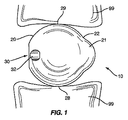
椎骨部分の間に挿入されるスペーサ(10)。スペーサは、第1の形状を有する前方セクション(20)および異なる形状を有する後方セクション(21)を備えた非球形状を有する。連結手段(30)は前方セクション内に配置され、挿入デバイスに連結するための受け部、およびスペーサを挿入デバイスから取り外す助けをする回転防止機構(32)を含むことができる。スペーサが非球形状であるため、椎間腔内で位置合せが行われ、連結機構の椎骨部分との接触が防止される。スペーサの椎骨部分の間への全般的に後方からの挿入を含むことができる、スペーサを使用する実施形態も開示する。挿入後、挿入デバイスは、連結機構を受け部から取り外すように回転防止デバイスと作用する。スペーサは椎骨部分の間に残され、患者の苦痛を軽減する。
【選択図】図1A spacer (10) inserted between the vertebral parts. The spacer has an aspheric shape with a front section (20) having a first shape and a rear section (21) having a different shape. The coupling means (30) may be disposed in the front section and may include a receiver for coupling to the insertion device and an anti-rotation mechanism (32) to assist in removing the spacer from the insertion device. Since the spacer is non-spherical, alignment is performed within the intervertebral space and contact with the vertebral portion of the coupling mechanism is prevented. Also disclosed is an embodiment using a spacer that can include insertion generally posteriorly between the vertebral portions of the spacer. After insertion, the insertion device acts with the anti-rotation device to remove the coupling mechanism from the receiving part. Spacers are left between the vertebral portions to reduce patient pain.
[Selection] Figure 1
Description
本発明は、非円形の安定球および方法に関する。 The present invention relates to non-circular stable spheres and methods.
人の脊椎は、33個の椎骨部分からなる生体力学構造を持ち、脊髄、神経根、ならびに胸部および腹部の臓器を保護する働きをする。脊椎は、柔軟な運動を可能にしながら身体に構造的支持を与える。人口の大半が人生のある時期に脊椎の状態が原因の背中の痛みを経験する。この痛みは、全身の不快感から個人が動けず何もできなくなる痛みまで広い範囲に及ぶ。背中の痛みは脊椎の損傷に起因することもあり、自然の加齢、または消耗性の疾患もしくは状態から生じることもある。 The human spine has a biomechanical structure consisting of 33 vertebrae and serves to protect the spinal cord, nerve roots, and thoracic and abdominal organs. The spine provides structural support to the body while allowing flexible movement. The majority of the population experiences back pain due to spinal conditions at some point in their lives. This pain can range from discomfort in the whole body to pain that makes the individual unable to move and do nothing. Back pain can result from spinal injury, or it can result from natural aging or from debilitating diseases or conditions.
こうした問題を改善のための処置では、スペーサの挿入による椎骨部分間の距離の修正が必要とされることがある。スペーサは、椎間板隙内に慎重に位置付けられ、椎骨部分に対して位置合せされる。スペーサは背中の痛みを緩和するように椎骨部分に配置されるサイズである。 Procedures to remedy these problems may require correction of the distance between vertebral portions by insertion of spacers. The spacer is carefully positioned within the intervertebral disc space and aligned with the vertebral portion. The spacer is sized to be placed on the vertebrae to relieve back pain.
スペーサは、身体内に挿入しやすいように設計される。形状およびサイズは、挿入中に患者への侵入を最小限に抑え、挿入後も有効に痛みを緩和し、患者に最大の運動性を与えるものである。 The spacer is designed to be easily inserted into the body. The shape and size minimizes entry into the patient during insertion, effectively relieves pain after insertion, and gives the patient maximum mobility.
スペーサは、スペーサを身体内に配置するための挿入デバイスへの連結装置を備えることもできる。連結装置は、スペーサを正確に挿入し配置するように挿入デバイスに対して十分な強度を有する必要がある。さらに連結装置は、スペーサを身体内に残したまま挿入デバイスを除去する分離装置も備えなければならない。連結装置はさらに、身体内で使用される部材の機能を妨げてはならない。 The spacer may also comprise a coupling device to an insertion device for placing the spacer in the body. The coupling device needs to have sufficient strength against the insertion device to correctly insert and place the spacer. Furthermore, the coupling device must also comprise a separating device that removes the insertion device while leaving the spacer in the body. The coupling device should also not interfere with the function of the members used in the body.
本発明の一実施形態は身体内に配置されるスペーサを対象とする。
一実施形態は、球形状を有する第1のセクション、および第1のセクションから外側に第1の方向に延びる第2のセクションを特徴とする。挿入デバイスに取り付けるための連結機構を第1のセクション上に位置付けることができる。
One embodiment of the present invention is directed to a spacer disposed within the body.
One embodiment features a first section having a spherical shape and a second section extending outwardly from the first section in a first direction. A coupling mechanism for attachment to the insertion device can be positioned on the first section.
さらに、回転防止機構を連結機構に隣接して位置付けて、挿入デバイスを除去しやすくすることができる。スペーサが非球形状であるため、椎間腔内で位置合せが行われ、連結機構の椎骨部分との接触が防止される。 Furthermore, the anti-rotation mechanism can be positioned adjacent to the coupling mechanism to facilitate removal of the insertion device. Since the spacer is non-spherical, alignment is performed within the intervertebral space and contact with the vertebral portion of the coupling mechanism is prevented.
本発明の一実施形態は、第1と第2の椎骨部分99の間に挿入するための、図1で全般的に10で示したスペーサを対象とする。スペーサ10は、第1のセクション20および第2のセクション21からなる全般的に非球形状を有する。第1および第2のセクション20、21は、スペーサ10が全般的に非球形状になるように重なる方向に配置される。連結機構30を第1および第2のセクション20、21のうちの1つの中に配置することができる。連結機構30は、非球形スペーサ10上で、椎骨部分99から離れたままであり、椎骨部分99との接触が回避される位置に配置される。
One embodiment of the present invention is directed to a spacer, generally designated 10 in FIG. 1, for insertion between first and second
図1で示した第1の実施形態のスペーサ10は、第1のセクション20および第2のセクション21からなる全般的に非球形状を有する。この非球形状により下面28および上面29が椎骨部分99と接触状態のスペーサ10の方向付けが維持される。図2は第1の実施形態のスペーサ10を示す概略図である。第1のセクション20は、スペーサ10の大部分を形成し、第2のセクション21よりも大きい表面積を有する。第1のセクション20は、中心点C1から延びる半径R1を有する実質的に球形である。第2のセクション21は、第1のセクション20から第1の方向に外側に延びる。この実施形態では、第2のセクション21は第1のセクション20の腹側に位置付けられる。
The
第2のセクション21は、中心点C2から延びる半径R2を有する実質的に球形である。両方の中心点C1およびC2は、共通の中心線Aに沿って位置合せされる。
図2は、スペーサ10の外面を実線で示す。破線は第1と第2のセクション20と21の重ねられた領域を示す。一実施形態では、第1および第2のセクション20、21はスペーサ10の全長が約9.6mmになるように位置合せされる。
The
FIG. 2 shows the outer surface of the
移行セクション22は、図2で示したように、第1のセクション20の外面が第2のセクション21の外面と合併される領域に沿って位置付けられる。第1のセクション20に対する第2のセクション21の突出により、移行セクション22が、図2で示したように凸面になり、図10で示したように接線になり、または図11で示したように凹面になる。
The
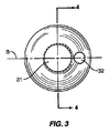
連結機構30は挿入デバイス50を取り付けるための受け部31を含む。図3の実施形態で示したように、受け部31は、スペーサ10内の長手方向の中心線Aと横方向の中心線Bに心合せされた開口部を含む。開口部31は挿入デバイス50に取り付けるためのねじ山を備えることができる。一実施形態では、受け開口部31の深さは約3.7mmである。回転防止機構32を連結機構30に近接して位置付けることもできる。回転防止機構32は挿入デバイス50と相互作用して、スペーサ10を除去しやすくする。回転防止機構32は受け部31からの除去中に挿入デバイス50によって加えられる力に逆トルクを加える。回転防止機構32は挿入デバイス30を除去するためのてこ作用をする。図3の実施形態では、機構32は、スペーサ10内に延び受け開口部31から離れて配置された開口部を含む。連結機構30はスペーサ10上に椎骨部分99から離れたまま配置される。図1の実施形態では、連結機構30はスペーサ10の後方に配置される。スペーサ10が非球形状であるため、第1のセクション20の上面29および下面28が椎骨部分99と接触状態に維持され、連結機構30が椎骨部分99から離れた位置に維持される。一例として、スペーサ10が比較的大きく回転され、図1の実施形態が使用される場合、スペーサ10が第1の方向(時計回り)に回転した場合は、第2のセクション21の下面が下方の椎骨部分と接触して、連結機構30と上方の椎骨部分の接触が防止される。スペーサ10が第2の方向(反時計回り)に回転した場合、第2のセクション21の上面が上方の椎骨部分と接触して、連結機構30と下方の椎骨部分の接触が防止される。連結機構30の縁部が椎骨部分99と接触するように配置されると、傷害を与える恐れがある。
The
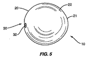
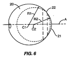
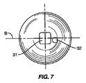
図5、6、および7は、スペーサ10の他の実施形態を示す。スペーサ10はやはり第1のセクション20、第2のセクション21、および移行セクション22を含む。第1のセクション20は、中心点C1の周りの半径R1を有する実質的に球形である。第2のセクション21も、中心点C2の周りの半径R2を有する実質的に球形である。移行セクション22は、第1のセクション20と第2のセクション21の間の連続した外面を形成する。図5および6の実施形態で示したように、第2のセクション21は第1のセクション20と比較してあまり目立たない。これは、サイズが同様であり(すなわち半径R1とR2が近い)、中心点C1とC2が近接しているために生じる。
5, 6 and 7 show another embodiment of the
連結機構30は、第1のセクション20上の椎骨部分99から離れた位置に配置され、矩形の受け開口部31を含む。開口部を含む回転防止機構32も、連結機構30に近接して配置される。各開口部31、32は、所定の距離だけスペーサ10内に延びるが、受け開口部31はより長い距離にわたって延びる。図6で示したように、中心線Aは受け開口部31の中央、および第1および第2のセクション20、21の中心点C1、C2も通って延びる。この実施形態では、開口部32は中心線Bからオフセットされる。図8および9は、第1のセクション20、第2のセクション21、および移行セクション22を有するスペーサ10の他の実施形態を示す。第1のセクション20は、中心線Aに沿って位置付けられた中心点C1および半径R1を有する。第2のセクション21は、中心線Aに沿って位置付けられた中心点C2および半径R2を有する。
The
開示された各実施形態は、スペーサ10の後方セクション内に位置付けられた連結機構30および回転防止機構32を含む。この配置により後方挿入手法が可能になる。理解されるように、こうした要素を、腹側挿入手法のための前方セクション、または横からの手法のための横方向の縁部に沿った位置など、スペーサ10上の他の位置に配置することもできる。各実施形態では、こうした要素の位置付けを、損傷を回避するために椎骨部分99から離れるようにすることができる。
Each disclosed embodiment includes a
図10は、実質的に接線の移行セクション22を有する一実施形態を示す。第1のセクション20は、中心線Aに沿って位置付けられた半径R1を有する実質的に球形である。第2のセクション21は、第1のセクション20の第1の側面から外側に延びる。この実施形態では、第2のセクション21は中心線Aに心合せされる。移行セクション22は第1のセクション20から実質的に接線方向に延びる。
FIG. 10 shows an embodiment having a substantially
図11は、凹面の移行セクション22を有する他の実施形態を示す。図12は、組み合わせた移行セクション22を有する一実施形態を示す。上方移行セクションは凸面形状を有し、下方の移行セクションは凹面形状を有する。移行セクション22の方向および曲率は適用例に応じて変えることができる。
FIG. 11 shows another embodiment having a
第1のセクション20の側面から延びる第2のセクション21の形状およびサイズは、必要に応じて変えることができる。図13は、組み合わせた構成を有する第2のセクション21を示す。上方移行セクション22は段付き構成を有し、下方移行セクションは凸面の方向付けがなされている。図14は、第1のセクション20の側面から外側に延び、第1のセクション20から反対側の端部27を有する円筒形の第2のセクション21を示す。図15は、第2のセクション21を形成し、第1のセクション20の側面から延びるリムフランジを有する一実施形態を示す。第2のセクション21は、第1のセクション20の球形状に併合されるように端部にテーパを付けた薄い厚さを有する。
The shape and size of the
図16は、球形の第1のセクション20の周囲に延びる溝24を有する他の実施形態を示す。溝24は適用例によって異なる深さを有することができる。図16の実施形態の溝24は中心線Aに沿って心合せされる。第2のセクション21は、第1のセクション20の側面から外側に延びる第1および第2の拡張部21a、21bを備える。第1のセクション21aは溝24の上方に位置付けられ、第2のセクション21bは溝24の下方に位置付けられる。
FIG. 16 shows another embodiment having a
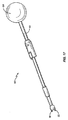
図17は、スペーサ10を椎骨部分99の間の椎骨腔内に挿入するための挿入デバイス50の一実施形態を示す。挿入デバイス50は、第2の細長い部材52に可動に取り付けられた第1の細長い部材51を備える。第2の細長い部材52は、医師が把持し操作する近位端に取り付けられたハンドル54を備える。受け部コネクタ55は第1の部材51の遠位端から外側に延びる。受け部コネクタ55は、受け開口部31上のねじと対合し、スペーサ10を挿入デバイス50に取り付けるようにねじが付けられる。第1の部材51は遠位端に回転防止コネクタ56を備える。第1の部材51は、第2の部材52に沿って、回転防止機構32と接触状態のコネクタ56の係合位置と、回転防止機構32から離れたコネクタ56の非係合位置との間で可動である。一実施形態では、回転コネクタ56は回転防止機構32を形成する小凹部内に嵌合されるピンを備える。
FIG. 17 illustrates one embodiment of an
使用の際は、身体の外部で受け部コネクタ55がスペーサ10の受け開口部31内にねじ込まれる。次いで、スペーサ10がハンドル54を把持する医師によって身体内に挿入される。スペーサ10が椎骨部分99の間に位置付けられた後、ピン32が回転防止機構32を形成する小凹部内に位置付けられる係合位置まで第1の部材51が第2の部材52を摺動する。次いで、ハンドル54を回転して受け部コネクタ55を回転させ、受け開口部31からコネクタ55のねじを解く。回転防止機構32内のコネクタ56の接触によってスペーサ10全体の回転が阻止される。ねじが解かれた後、スペーサ10を身体内に残したまま、挿入デバイス50が除去される。
In use, the receiving
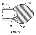
図18は受け開口部31の他の実施形態を示す。この実施形態はテーパを付けた開口部を特徴とし、受け部コネクタ55は対応するテーパが付けられた構成を有する。受け部コネクタ55を開口部31内に挿入することができ、テーパは2つの部材を共に連結する係止部として働く。一実施形態では、コネクタ55は開口部31内に位置付けられ、患者の身体内に配置される。ハンドル54を木槌で軽く叩いて、コネクタ55を取り外し、スペーサ10を残したまま挿入デバイス50を患者から除去する。図19は、テーパを付けた受け部コネクタ55および1対の回転防止アーム56を有する一実施形態を示す。アーム56は第1のセクション20の外部と一致する遠位端を有する。アーム56を遠位端が第1のセクション20と接触するように受け部コネクタ55に対して外側に移動し、力を加えて、テーパを付けた受け部コネクタ55を開口部31から取り外すことができる。
FIG. 18 shows another embodiment of the receiving
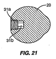
図20は、開口部31内に位置付けられたくぼみ39を有する他の実施形態を示す。この実施形態で使用するには、コネクタ55は、くぼみ39内に嵌合されて挿入デバイス50をスペーサ10に係止するボール移動止めを備える。図21は、同軸の受けコネクタ55および回転防止コネクタ56を有する挿入デバイス50で使用される一実施形態を示す。開口部の第1のセクション31aはコネクタ55、56の1つを受けるサイズであり、第2のセクション31bは他方のコネクタを受けるサイズである。コネクタ55はコネクタ56の内部でも外部でもよい。セクション31a、31bは、形状が六角形など多角形でもよく、ねじを付けることができ、またはその組合せでもよい。
FIG. 20 shows another embodiment having an
他の実施形態では、受け部コネクタ55はアームを備え、アームは、第1の部材51から外側に延びる拡張位置と、アームが第1の部材51に近接した引込み位置との間で可動である。ハンドル54は、スペーサ10を取り付けるためにアームが受け開口部31に押し付けられた状態の拡張位置にアームを選択的に位置付けるように可動である。挿入されて適切に位置付けられた後にハンドル54が作動され、アームが引込み位置に移動され、挿入デバイス50をスペーサ10から除去することができる。この実施形態では、回転防止デバイス32が不要であり、連結手段30は受け部31を含む。
In other embodiments, the
挿入デバイス50の連結用の他のデバイスは、スナップ式嵌合、カムロック、干渉六角形、ボール解放機構を含む。連結機構30は、穿孔された開口、切欠き、溝、タブ、粗面、スプライン、および吸引または把持機構を含む多様な実施形態を含むことができる。
Other devices for coupling the
上記で論じた例示の実施形態は、部材50が単一の椎間板を置換することが想定されているが、本発明は、部材50が、2つ以上の椎間板を置換する状況、いわゆる椎体切除術(corpectomy)構成も包含する。これは、デバイス10に取り付け、それから取り外すことができる比較的大きい部材50、または複数の部材50を使用して行うことができる。
Although the exemplary embodiment discussed above assumes that
また、上記で示し記載したデバイスおよび方法は脊椎の腰椎部位の治療に特に有用であるが、理解されるように、本発明を、頚部、胸部、および仙腸骨部位を含む脊椎の他の部分に適用することもできる。 Also, while the devices and methods shown and described above are particularly useful in the treatment of lumbar spine sites of the spine, it will be appreciated that the present invention can be applied to other parts of the spine including the cervical, thoracic, and sacroiliac sites. It can also be applied to.
用語「椎骨部分」などは、椎体、椎弓根、椎弓板、および突起を含む椎骨の形状を全般的に記載するために使用される。同様に、用語「椎間腔」などは、椎骨部分の間の腔を全般的に記載するために使用される。椎間腔は、隣接する椎骨部分の間、または非隣接椎骨部分の間に形成される。スペーサ10は、脊椎の様々な部位内で使用されるサイズおよび形状でもよく、十分な強度要件を満たすことができる。
The terms “vertebral part” and the like are used to generally describe the shape of a vertebra, including the vertebral body, pedicle, lamina, and process. Similarly, the terms “intervertebral space” and the like are used to describe generally the space between vertebral portions. The intervertebral space is formed between adjacent vertebra parts or between non-adjacent vertebra parts. The
図1および2の実施形態は、第2のセクション21から反対側の実質的に平坦なセクションを有する第1のセクション20を示す。一実施形態では、連結機構30はこの平坦なセクション内に配置される。他の実施形態では、第1のセクション20は平坦なセクションを含まず、実質的に平坦なセクションを含むことができない。
The embodiment of FIGS. 1 and 2 shows a
用語「スペーサ10」は、椎骨部分99の間に配置されるデバイスを記載するために一般的な意味で本明細書で使用される。一実施形態では、スペーサ10は身体内に残されるインプラントである。他の実施形態では、スペーサ10はジグであり、インプラントを受けるための椎骨部分または椎間腔などの部位を用意するために、切断、計測、または腔維持デバイスを案内あるいは保持する取付具もしくはデバイスである。こうした実施形態では、スペーサ10を処置の完了時に身体から除去することができる。
The term “
本発明の範囲および本質的な特徴から逸脱することなく、本発明の他の実施形態を、本明細書で述べた以外の他の特定の方法で実施することができる。用語「上方」、「下方」、「内側」、「外側」などは、様々な要素の相対位置を記載するための用語であり、一般的な意味で使用される。スペーサ10は図4で示したように固体でもよく、または内部が中空でもよい。受け開口部31は、ねじを付けても付けなくてもよく、様々なサイズ、様々な径、かつ多様な形状(例えば円形、矩形など)でもよい。したがって、本発明の実施形態はあらゆる点で例示であって限定的なものではないと考えられるべきであり、添付の特許請求の範囲の意義および等価の範囲内の変更はすべてその中に包含されるものとする。
Other embodiments of the invention may be implemented in other specific ways than described herein without departing from the scope and essential characteristics of the invention. The terms “upper”, “lower”, “inner”, “outer” and the like are terms used to describe the relative positions of various elements and are used in a general sense. The
Claims (19)
前記第1のセクションの第1の側面から外側に延び、第2の外面および第2の半径を有し、前記第2の半径が前記第1の半径よりも小さい、第2の球状セクションとを備え、
前記第1および第2の球状セクションが重ねられた配置になされ、細長い非球形状を形成する、椎骨間デバイス。 A first spherical section having a first radius and a first outer surface;
A second spherical section extending outwardly from a first side of the first section, having a second outer surface and a second radius, wherein the second radius is less than the first radius; Prepared,
An intervertebral device, wherein the first and second spherical sections are placed in an overlapping configuration to form an elongated non-spherical shape.
弓形外面を有する第1のセクションと、
前記第1のセクションから外側に第1の方向に延びる第2のセクションと、
前記第2のセクションから反対側の前記第1のセクション内に位置付けられる連結機構とを備え、
前記第2のセクションがある距離だけ外側に延びた状態で前記弓形外面が前記椎骨部分と接触状態であり、前記第1のセクションの移動を最小限に抑えて、前記連結機構が前記椎骨部分から離れて維持されるようになされたデバイス。 An intervertebral device positioned between vertebral portions,
A first section having an arcuate outer surface;
A second section extending outwardly from the first section in a first direction;
A coupling mechanism positioned in the first section opposite the second section;
The arcuate outer surface is in contact with the vertebral portion with the second section extending outward by a distance, and the coupling mechanism is disengaged from the vertebral portion with minimal movement of the first section. A device designed to be kept away.
Applications Claiming Priority (2)
| Application Number | Priority Date | Filing Date | Title |
|---|---|---|---|
| US11/098,167 US8083798B2 (en) | 2005-04-04 | 2005-04-04 | Non-circular stabilization sphere and method |
| PCT/US2006/012372 WO2006107898A1 (en) | 2005-04-04 | 2006-04-03 | Non-circular stabilization sphere and method |
Publications (2)
| Publication Number | Publication Date |
|---|---|
| JP2008534222A true JP2008534222A (en) | 2008-08-28 |
| JP2008534222A5 JP2008534222A5 (en) | 2009-05-14 |
Family
ID=36693512
Family Applications (1)
| Application Number | Title | Priority Date | Filing Date |
|---|---|---|---|
| JP2008505428A Pending JP2008534222A (en) | 2005-04-04 | 2006-04-03 | Non-circular ball and method |
Country Status (6)
| Country | Link |
|---|---|
| US (1) | US8083798B2 (en) |
| EP (1) | EP1885297A1 (en) |
| JP (1) | JP2008534222A (en) |
| AU (1) | AU2006232555A1 (en) |
| CA (1) | CA2603496A1 (en) |
| WO (1) | WO2006107898A1 (en) |
Families Citing this family (18)
| Publication number | Priority date | Publication date | Assignee | Title |
|---|---|---|---|---|
| US7648509B2 (en) | 2003-03-10 | 2010-01-19 | Ilion Medical Llc | Sacroiliac joint immobilization |
| US8172855B2 (en) | 2004-11-24 | 2012-05-08 | Abdou M S | Devices and methods for inter-vertebral orthopedic device placement |
| US20090024174A1 (en) | 2007-07-17 | 2009-01-22 | Stark John G | Bone screws and particular applications to sacroiliac joint fusion |
| US8740912B2 (en) | 2008-02-27 | 2014-06-03 | Ilion Medical Llc | Tools for performing less invasive orthopedic joint procedures |
| US8518113B2 (en) * | 2008-05-20 | 2013-08-27 | Warsaw Othopedic, Inc. | Intervertebral implant and methods of implantation and manufacture |
| US9011538B2 (en) | 2009-01-21 | 2015-04-21 | Warsaw Orthopedic, Inc. | Methods of spinal nucleus replacemennt |
| US9011539B2 (en) * | 2009-01-21 | 2015-04-21 | Warsaw Orthopedic, Inc. | Spinal nucleus replacement implant |
| US8292962B2 (en) * | 2009-03-04 | 2012-10-23 | Warsaw Orthopedic, Inc. | Spinal nucleus replacement implants |
| US8764806B2 (en) | 2009-12-07 | 2014-07-01 | Samy Abdou | Devices and methods for minimally invasive spinal stabilization and instrumentation |
| US8926665B2 (en) * | 2010-03-18 | 2015-01-06 | Facsecure, Llc | Cortical, anti-migration, facet dowel for fusion of facet joints in the spine and devices for setting the same in place |
| US8845728B1 (en) | 2011-09-23 | 2014-09-30 | Samy Abdou | Spinal fixation devices and methods of use |
| US20130226240A1 (en) | 2012-02-22 | 2013-08-29 | Samy Abdou | Spinous process fixation devices and methods of use |
| US9198767B2 (en) | 2012-08-28 | 2015-12-01 | Samy Abdou | Devices and methods for spinal stabilization and instrumentation |
| US9320617B2 (en) | 2012-10-22 | 2016-04-26 | Cogent Spine, LLC | Devices and methods for spinal stabilization and instrumentation |
| US10857003B1 (en) | 2015-10-14 | 2020-12-08 | Samy Abdou | Devices and methods for vertebral stabilization |
| US10744000B1 (en) | 2016-10-25 | 2020-08-18 | Samy Abdou | Devices and methods for vertebral bone realignment |
| US10973648B1 (en) | 2016-10-25 | 2021-04-13 | Samy Abdou | Devices and methods for vertebral bone realignment |
| US11179248B2 (en) | 2018-10-02 | 2021-11-23 | Samy Abdou | Devices and methods for spinal implantation |
Citations (1)
| Publication number | Priority date | Publication date | Assignee | Title |
|---|---|---|---|---|
| US20030135276A1 (en) * | 2002-01-17 | 2003-07-17 | Concept Matrix, Llc | Vertebral defect device |
Family Cites Families (32)
| Publication number | Priority date | Publication date | Assignee | Title |
|---|---|---|---|---|
| US4714469A (en) * | 1987-02-26 | 1987-12-22 | Pfizer Hospital Products Group, Inc. | Spinal implant |
| US5458638A (en) * | 1989-07-06 | 1995-10-17 | Spine-Tech, Inc. | Non-threaded spinal implant |
| US4936848A (en) * | 1989-09-22 | 1990-06-26 | Bagby George W | Implant for vertebrae |
| US5059193A (en) * | 1989-11-20 | 1991-10-22 | Spine-Tech, Inc. | Expandable spinal implant and surgical method |
| US5026392A (en) * | 1990-05-21 | 1991-06-25 | Gordon Gregg E | Prosthetic eye |
| US5645596A (en) * | 1993-07-07 | 1997-07-08 | Asahi Kogaku Kogyo Kabushiki Kaisha | Ceramic vertebrae prosthesis |
| US5466259A (en) * | 1994-03-07 | 1995-11-14 | Durette; Jean-Francois | Orbital implant and method |
| US6093207A (en) * | 1994-03-18 | 2000-07-25 | Pisharodi; Madhavan | Middle expanded, removable intervertebral disk stabilizer disk |
| US5571189A (en) | 1994-05-20 | 1996-11-05 | Kuslich; Stephen D. | Expandable fabric implant for stabilizing the spinal motion segment |
| US5431657A (en) * | 1994-05-23 | 1995-07-11 | Zimmer, Inc. | Instrument for installing an acetabular cup assembly |
| US5743918A (en) * | 1996-05-13 | 1998-04-28 | Wright Medical Technology, Inc. | Instrumentation for and method for implanting a spherical prosthesis |
| US7306628B2 (en) * | 2002-10-29 | 2007-12-11 | St. Francis Medical Technologies | Interspinous process apparatus and method with a selectably expandable spacer |
| US7101375B2 (en) * | 1997-01-02 | 2006-09-05 | St. Francis Medical Technologies, Inc. | Spine distraction implant |
| US5935169A (en) * | 1997-02-13 | 1999-08-10 | Chan; Kwan-Ho | Bone cement plug for deployment in a bone canal |
| US5888226A (en) * | 1997-11-12 | 1999-03-30 | Rogozinski; Chaim | Intervertebral prosthetic disc |
| FR2797179B1 (en) * | 1999-08-03 | 2002-03-08 | Michel Gau | INTERVERTEBRAL NUCLEAR PROSTHESIS AND SURGICAL IMPLANTATION METHOD |
| US6245074B1 (en) * | 1999-09-01 | 2001-06-12 | Bristol-Myers Squibb Co. | Orthopaedic glenoid reamer |
| US6319257B1 (en) * | 1999-12-20 | 2001-11-20 | Kinamed, Inc. | Inserter assembly |
| US6733531B1 (en) | 2000-10-20 | 2004-05-11 | Sdgi Holdings, Inc. | Anchoring devices and implants for intervertebral disc augmentation |
| US6989032B2 (en) * | 2001-07-16 | 2006-01-24 | Spinecore, Inc. | Artificial intervertebral disc |
| US6478822B1 (en) | 2001-03-20 | 2002-11-12 | Spineco, Inc. | Spherical spinal implant |
| FR2829689B1 (en) | 2001-09-14 | 2004-06-25 | Frederic Fortin | NUCLEUS PROSTHESIS AND ITS INSERTION DEVICE AND ITS POSITIONING METHOD |
| US6641613B2 (en) * | 2002-01-30 | 2003-11-04 | Cortek, Inc. | Double dowel spinal fusion implant |
| US20060106462A1 (en) | 2002-04-16 | 2006-05-18 | Tsou Paul M | Implant material for minimally invasive spinal interbody fusion surgery |
| US20040093082A1 (en) * | 2002-04-19 | 2004-05-13 | Ferree Bret A. | Mobile-bearing artificial disc replacement |
| US20040030391A1 (en) * | 2002-04-24 | 2004-02-12 | Bret Ferree | Artificial intervertebral disc spacers |
| US7179294B2 (en) * | 2002-04-25 | 2007-02-20 | Warsaw Orthopedic, Inc. | Articular disc prosthesis and method for implanting the same |
| US20040024461A1 (en) * | 2002-05-10 | 2004-02-05 | Ferree Bret A. | Spring and spherical joint artificial disc replacements |
| US7001433B2 (en) * | 2002-05-23 | 2006-02-21 | Pioneer Laboratories, Inc. | Artificial intervertebral disc device |
| US7824444B2 (en) * | 2003-03-20 | 2010-11-02 | Spineco, Inc. | Expandable spherical spinal implant |
| US7806933B2 (en) * | 2004-03-15 | 2010-10-05 | Warsaw Orthopedic, Inc. | System and method for stabilizing a prosthetic device |
| US9011538B2 (en) * | 2009-01-21 | 2015-04-21 | Warsaw Orthopedic, Inc. | Methods of spinal nucleus replacemennt |
-
2005
- 2005-04-04 US US11/098,167 patent/US8083798B2/en not_active Expired - Fee Related
-
2006
- 2006-04-03 EP EP06740432A patent/EP1885297A1/en not_active Withdrawn
- 2006-04-03 CA CA002603496A patent/CA2603496A1/en not_active Abandoned
- 2006-04-03 AU AU2006232555A patent/AU2006232555A1/en not_active Abandoned
- 2006-04-03 JP JP2008505428A patent/JP2008534222A/en active Pending
- 2006-04-03 WO PCT/US2006/012372 patent/WO2006107898A1/en active Application Filing
Patent Citations (1)
| Publication number | Priority date | Publication date | Assignee | Title |
|---|---|---|---|---|
| US20030135276A1 (en) * | 2002-01-17 | 2003-07-17 | Concept Matrix, Llc | Vertebral defect device |
Also Published As
| Publication number | Publication date |
|---|---|
| EP1885297A1 (en) | 2008-02-13 |
| US20060224240A1 (en) | 2006-10-05 |
| WO2006107898A1 (en) | 2006-10-12 |
| US8083798B2 (en) | 2011-12-27 |
| AU2006232555A1 (en) | 2006-10-12 |
| CA2603496A1 (en) | 2006-10-12 |
Similar Documents
| Publication | Publication Date | Title |
|---|---|---|
| JP2008534222A (en) | Non-circular ball and method | |
| US11039864B2 (en) | Rod reduction device and method of use | |
| JP6728411B2 (en) | Tissue retracting and vertebral displacement devices, systems and methods for posterior spinal fusion | |
| US11672571B2 (en) | Cervical spine stabilization system with extendable plates | |
| ES2260888T3 (en) | BLOCKING DEVICE FOR FIXING THE SPINAL COLUMN. | |
| JP4139493B2 (en) | Suture anchor recovery device and recovery method | |
| JP4988735B2 (en) | Rod extension for elongating fusion structures | |
| US9642723B2 (en) | Spinal implants and insertion instruments | |
| ES2526098T3 (en) | Spinal fixation system that has locking and unlocking devices for use with a conical multiplanar locking screw | |
| US8864770B2 (en) | Offset opposing arm spinal implant distractor/inserter | |
| US7976549B2 (en) | Instruments for delivering spinal implants | |
| US8764754B2 (en) | Systems and methods for spinal rod insertion and reduction | |
| US20170224390A1 (en) | Expandable interspinous device | |
| US7559930B2 (en) | Surgical tool and method with an actuation mechanism for controlling reciprocation and locking of an anti-rotation member relative to an engagement member for facilitating positioning of an intervertebral device | |
| JP5529270B2 (en) | Bone plate locking system and method of using bone plate locking system | |
| US8690923B2 (en) | Bone fixation systems and methods | |
| US20140172030A1 (en) | Adjustable interbody introducer device and method | |
| US20170079696A1 (en) | Spinal Fixation System | |
| JP2009511227A (en) | Adjustable bone anchor assembly | |
| JP2002508679A (en) | Artificial facet joint allowing translation and rotation | |
| US9545270B2 (en) | Universal rod holder | |
| KR20040024683A (en) | Pedicle screw and pedicle screw assembly having the same |
Legal Events
| Date | Code | Title | Description |
|---|---|---|---|
| A521 | Written amendment |
Free format text: JAPANESE INTERMEDIATE CODE: A523 Effective date: 20090327 |
|
| A621 | Written request for application examination |
Free format text: JAPANESE INTERMEDIATE CODE: A621 Effective date: 20090327 |
|
| A131 | Notification of reasons for refusal |
Free format text: JAPANESE INTERMEDIATE CODE: A131 Effective date: 20101028 |
|
| A977 | Report on retrieval |
Free format text: JAPANESE INTERMEDIATE CODE: A971007 Effective date: 20101104 |
|
| A02 | Decision of refusal |
Free format text: JAPANESE INTERMEDIATE CODE: A02 Effective date: 20110404 |