JP2008530754A - Snap lock connection terminal - Google Patents
Snap lock connection terminal Download PDFInfo
- Publication number
- JP2008530754A JP2008530754A JP2007555127A JP2007555127A JP2008530754A JP 2008530754 A JP2008530754 A JP 2008530754A JP 2007555127 A JP2007555127 A JP 2007555127A JP 2007555127 A JP2007555127 A JP 2007555127A JP 2008530754 A JP2008530754 A JP 2008530754A
- Authority
- JP
- Japan
- Prior art keywords
- ring
- housing
- wall
- socket
- ground contact
- Prior art date
- Legal status (The legal status is an assumption and is not a legal conclusion. Google has not performed a legal analysis and makes no representation as to the accuracy of the status listed.)
- Pending
Links
Images


Classifications
-
- H—ELECTRICITY
- H01—ELECTRIC ELEMENTS
- H01R—ELECTRICALLY-CONDUCTIVE CONNECTIONS; STRUCTURAL ASSOCIATIONS OF A PLURALITY OF MUTUALLY-INSULATED ELECTRICAL CONNECTING ELEMENTS; COUPLING DEVICES; CURRENT COLLECTORS
- H01R13/00—Details of coupling devices of the kinds covered by groups H01R12/70 or H01R24/00 - H01R33/00
- H01R13/40—Securing contact members in or to a base or case; Insulating of contact members
- H01R13/42—Securing in a demountable manner
- H01R13/428—Securing in a demountable manner by resilient locking means on the contact members; by locking means on resilient contact members
- H01R13/434—Securing in a demountable manner by resilient locking means on the contact members; by locking means on resilient contact members by separate resilient locking means on contact member, e.g. retainer collar or ring around contact member
-
- H—ELECTRICITY
- H01—ELECTRIC ELEMENTS
- H01R—ELECTRICALLY-CONDUCTIVE CONNECTIONS; STRUCTURAL ASSOCIATIONS OF A PLURALITY OF MUTUALLY-INSULATED ELECTRICAL CONNECTING ELEMENTS; COUPLING DEVICES; CURRENT COLLECTORS
- H01R24/00—Two-part coupling devices, or either of their cooperating parts, characterised by their overall structure
- H01R24/38—Two-part coupling devices, or either of their cooperating parts, characterised by their overall structure having concentrically or coaxially arranged contacts
- H01R24/40—Two-part coupling devices, or either of their cooperating parts, characterised by their overall structure having concentrically or coaxially arranged contacts specially adapted for high frequency
-
- H—ELECTRICITY
- H01—ELECTRIC ELEMENTS
- H01R—ELECTRICALLY-CONDUCTIVE CONNECTIONS; STRUCTURAL ASSOCIATIONS OF A PLURALITY OF MUTUALLY-INSULATED ELECTRICAL CONNECTING ELEMENTS; COUPLING DEVICES; CURRENT COLLECTORS
- H01R13/00—Details of coupling devices of the kinds covered by groups H01R12/70 or H01R24/00 - H01R33/00
- H01R13/62—Means for facilitating engagement or disengagement of coupling parts or for holding them in engagement
- H01R13/629—Additional means for facilitating engagement or disengagement of coupling parts, e.g. aligning or guiding means, levers, gas pressure electrical locking indicators, manufacturing tolerances
- H01R13/633—Additional means for facilitating engagement or disengagement of coupling parts, e.g. aligning or guiding means, levers, gas pressure electrical locking indicators, manufacturing tolerances for disengagement only
-
- H—ELECTRICITY
- H01—ELECTRIC ELEMENTS
- H01R—ELECTRICALLY-CONDUCTIVE CONNECTIONS; STRUCTURAL ASSOCIATIONS OF A PLURALITY OF MUTUALLY-INSULATED ELECTRICAL CONNECTING ELEMENTS; COUPLING DEVICES; CURRENT COLLECTORS
- H01R2103/00—Two poles
-
- H—ELECTRICITY
- H01—ELECTRIC ELEMENTS
- H01R—ELECTRICALLY-CONDUCTIVE CONNECTIONS; STRUCTURAL ASSOCIATIONS OF A PLURALITY OF MUTUALLY-INSULATED ELECTRICAL CONNECTING ELEMENTS; COUPLING DEVICES; CURRENT COLLECTORS
- H01R4/00—Electrically-conductive connections between two or more conductive members in direct contact, i.e. touching one another; Means for effecting or maintaining such contact; Electrically-conductive connections having two or more spaced connecting locations for conductors and using contact members penetrating insulation
- H01R4/28—Clamped connections, spring connections
- H01R4/48—Clamped connections, spring connections utilising a spring, clip, or other resilient member
Abstract
本発明は、1つの局面において、特にRFまたは高速デジタル電気信号を必要とする用途に使用することができる接続端子装置(100)を与える。 In one aspect, the present invention provides a connection terminal device (100) that can be used particularly in applications requiring RF or high-speed digital electrical signals.
Description
この出願は、2005年7月19日に出願された米国仮特許出願番号第60/700,309号および2005年2月11日に出願された第60/651,637号の利益を主張する。上述の仮出願の全体が本願に援用される。 This application claims the benefit of US Provisional Patent Application No. 60 / 700,309, filed July 19, 2005 and 60 / 651,637, filed February 11, 2005. The entire provisional application described above is incorporated herein by reference.
発明の背景
発明の分野
本発明は、接続端子、より具体的には、スナップロック、RF接続端子に関する。
BACKGROUND OF THE INVENTION 1. Field of the Invention The present invention relates to connection terminals, and more particularly to snap locks and RF connection terminals.
背景の説明
RFまたは高速デジタル電気信号を必要とする用途で用いることができる電気接続端子のニーズがある。
Background Description There is a need for electrical connection terminals that can be used in applications requiring RF or high-speed digital electrical signals.
発明の概要
1つの局面では、本発明は、他の用途の中でも特にRFまたは高速デジタル電気信号を必要とする用途で使用することができる接続端子装置を与える。
SUMMARY OF THE INVENTION In one aspect, the present invention provides a connection terminal device that can be used in applications requiring RF or high-speed digital electrical signals, among other applications.
1つの実施例では、接続端子装置は、(1)ソケットを含み、ソケットは、ハウジングと、ハウジング内に配置された絶縁体と、絶縁体内に配置された第1のコンタクトと、ハウジング内に収容された接地コンタクトと、ハウジングの遠位端のまわりに配置されたロックリングと、ハウジングの遠位端およびロックリングのまわりに配置されてハウジングに相対して第1の位置および第2の位置の間で移動可能なシュラウドとを含み、シュラウドは外壁および内壁を有し、シュラウドが第1の位置から第2の位置に動くと内壁はロックリングに接触してロックリングを外向きに屈曲させ、さらに(2)プラグを含み、プラグは、絶縁体および絶縁体内に配置されたコンタクトを収容する一般に円筒状の導電性プラグハウジングを含み、ハウジングは、その外壁に、一方側に第1の傾斜面を有して反対側に第2の傾斜面を有する突起を有し、ソケットは、プラグがソケットの遠位端に挿入されてロックリングによって定位置にロックされるとロックリングがプラグハウジングの突起に軸方向力を及ぼすように構成されるが、この軸方向力は、プラグハウジングの前部表面がソケットのいずれの表面をも押圧するようにしない。 In one embodiment, the connection terminal device includes (1) a socket, and the socket is accommodated in the housing, the insulator disposed in the housing, the first contact disposed in the insulator, and the housing. Ground contact, a lock ring disposed about the distal end of the housing, and a first position and a second position disposed about the distal end of the housing and the lock ring relative to the housing. A shroud movable between the outer wall and the inner wall, and when the shroud moves from the first position to the second position, the inner wall contacts the lock ring and causes the lock ring to bend outwardly; And (2) a plug, the plug including a generally cylindrical conductive plug housing that houses the insulator and the contacts disposed within the insulator; And the socket has a protrusion having a first inclined surface on one side and a second inclined surface on the opposite side, and the socket has a locking ring with a plug inserted into the distal end of the socket. The locking ring is configured to exert an axial force on the plug housing protrusion when locked in place by the axial force, which causes the front surface of the plug housing to press against any surface of the socket. Do not like.
別の局面では、本発明は接続端子装置で使用するためのソケットを与える。1つの実施例では、ソケットは、ハウジングと、ハウジング内に配置された絶縁体と、絶縁体内に配置された第1のコンタクトと、ハウジングの内部表面に位置する環状溝内に収容された環状の接地コンタクトと、ハウジングの遠位端のまわりに配置されたロックリングと、ハウジングの遠位端およびロックリングのまわりに配置されてハウジングに相対して第1の位置および第2の位置の間で移動可能なシュラウドとを含み、シュラウドは外壁および内壁を有する。好ましい実施例において、シュラウドおよびロックリングは、シュラウドが第1の位置から第2の位置へ動くと内壁がロックリングに接触してロックリングを外向きに屈曲させるように構成される。 In another aspect, the present invention provides a socket for use with a connection terminal device. In one embodiment, the socket includes a housing, an insulator disposed within the housing, a first contact disposed within the insulator, and an annular groove housed in an annular groove located on the interior surface of the housing. A ground contact, a lock ring disposed about the distal end of the housing, and disposed between the first end and the second position relative to the housing disposed about the distal end and the lock ring of the housing. A movable shroud, the shroud having an outer wall and an inner wall. In a preferred embodiment, the shroud and lock ring are configured such that when the shroud moves from the first position to the second position, the inner wall contacts the lock ring and bends the lock ring outward.
別の局面では、本発明は、ソケットハウジングとプラグハウジングとの間に電気接続を確立する際に用いるための接地コンタクトを与える。1つの実施例では、接地コンタクトは、第1の分離リングと、第2の分離リングと、第1の分離リングを第2の分離リングに
接続する1つ以上の一般にU形状のコンタクトとを含み、分離リングは同軸になるよう配列される。
In another aspect, the present invention provides a ground contact for use in establishing an electrical connection between a socket housing and a plug housing. In one embodiment, the ground contact includes a first isolation ring, a second isolation ring, and one or more generally U-shaped contacts that connect the first isolation ring to the second isolation ring. The separation rings are arranged coaxially.
本発明のさまざまな局面の上記および他の機能ならびに利点と好ましい実施例の構造および動作とは、添付の図面を参照して詳細に下記に記述される。 The above and other features and advantages of various aspects of the present invention, as well as the structure and operation of preferred embodiments, are described in detail below with reference to the accompanying drawings.
本願明細書に援用されてその一部を形成する添付の図面は、本発明のさまざまな実施例を図示するのを助け、明細書とともに、本発明の原理について説明し、かつ当業者が本発明の実施例を実施して使用することを可能にするよう、さらに役立つ。図面において、同じ参照番号は、同一または機能的に類似の要素を表示する。 The accompanying drawings, which are incorporated in and constitute a part of this specification, assist in illustrating various embodiments of the invention, together with the description, explain the principles of the invention, and allow those skilled in the art to understand the invention. It is further helpful to be able to implement and use this embodiment. In the drawings, like reference numbers indicate identical or functionally similar elements.
好ましい実施例の詳細な説明
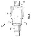
図1は、本発明の実施例によるスナップロック接続端子装置100の側面図である。接続端子装置100は第1の接続端子構成要素158(別名「ソケット構成要素158」)および第2の接続端子構成要素160(別名「プラグ160」)を含む。好ましくは、図1に示されるように、ソケット158はプラグ160を受取るように設計される。図1にさらに示されるように、ソケット158は、第1のハウジング102、第2のハウジング104およびシュラウド106を含んでもよい。
DETAILED DESCRIPTION OF PREFERRED EMBODIMENTS FIG. 1 is a side view of a snap lock
ここで図2を参照して、図2は1つの実施例による第1のハウジング102の断面の側面図である。示されるように、ハウジング102は一般に円筒状であってキャビティ201を規定し得る。ハウジング102はさらに第1の端部部分202、第2の端部部分206、および端部部分202と206との間に位置する中間部分204を有していてもよい。各部分202、204および206は外径および内径を有していてもよい。これらの内径および外径は均一でもよい。
Reference is now made to FIG. 2, which is a cross-sectional side view of a
好ましくは、端部部分206の外径(od1)は、中間部分204の外径(od2)より大きい。さらに、中間部分204の外径(od2)は、端部部分202の外径(od3)より大きくてもよい。さらに、端部部分206の内径(id1)は中間部分204の内径(id2)と等しくてもよく、中間部分204の内径(id2)は端部部分202の内径(id3)より大きくてもよく、それにより内壁211を形成する。
Preferably, the outer diameter (od1) of the
好ましくは、中間部分204と端部部分206との間に位置する円錐形の遷移部分205が与えられる。端部部分202と中間部分204との間にも円錐形の遷移部分203が与えられてもよい。遷移部分205は非均一な外径を有する。図2に示されるように、その最大部では、部分205の外径はod1に等しいかまたはほぼ等しく、かつその最小部では部分205の外径はod2に等しいかまたはほぼ等しい。
Preferably, a
ここで図3を参照して、図3は、ハウジング102のキャビティ201に収容された誘電体302とコンタクト204とを示す。示された実施例では、コンタクト204は細長く、誘電体302の長手軸およびハウジング102の長手軸と位置合わせされる長手軸を有する。誘電体302は、コンタクト304の少なくとも1つの部分を囲み、電気的に導電性のコンタクトをハウジング104から電気的に絶縁するよう機能する。
Referring now to FIG. 3, FIG. 3 shows the dielectric 302 and the
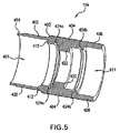
ここで図4および図5を参照して、図4は第2のハウジング104の断面の側面図であり、図5は第2のハウジング104の断面の斜視図であって、両図ともに1つの実施例による。示されるように、ハウジング104は一般に円筒状でもよい。ハウジング104はさらに、第1の端部部分402(すなわち点線Cの左側の部分)と、第2の端部部分406(すなわち点線Aの右側の部分)と、端部部分402および406の間(すなわち点線
BとCとの間の部分)に配置される中間部分404を有してもよい。各部分402、404および406は外径および内径を有し、キャビティを規定することができる。たとえば端部部分402はキャビティ401を規定し、端部部分406はキャビティ411を規定する。
4 and 5, FIG. 4 is a side view of the cross section of the
好ましくは、端部部分402と中間部分404との間に遷移部分403が与えられる。遷移部分403は非均一な外径を有する。図4に示されるように、その最大部では、部分403の外径は部分404の外径と等しいかほぼ等しく、その最小部では、部分403の外径は部分402の外径と等しいかほぼ等しい。
Preferably, a
図4および図5に示されるように、中間部分404は内向きに突出する環状のリブ422を含んでもよい。さらに、第1の凹部424aおよび第2の凹部424bは、両方とも環状でもよく、中間部分404の内部表面462に形成されてもよい。第1の凹部424aはリブ322と中間部分403との間に位置してもよい。第2の凹部424bはリブ322と端部部分406との間に位置してもよい。
As shown in FIGS. 4 and 5, the
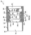
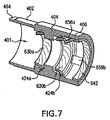
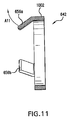
ここで図6および図7を参照して、図6および図7は、ハウジング104に収容された2つの導電性の接地コンタクト630aおよび630b、ならびにロックリング642を示す。1つの実施例による接地コンタクト630は図8および図9にも示される。
Referring now to FIGS. 6 and 7, FIGS. 6 and 7 show two
図8は接地コンタクト630の側面図であり、図9は接地コンタクトの斜視図であって、両図ともに1つの実施例による。示されるように、接地コンタクトは一般にリング形状であって、胴部管632と、胴部管632に接続され、胴部管632の外部表面から外向きに突出するフランジ部分631とを有してもよい。好ましくは、胴部管632は一般に円錐形である(たとえば、胴部管の一方側から他方側まで動くにつれて、胴部分632の外径および内径は徐々に増加/減少する)。フランジ部分631は、胴部管632の外径が最大になる部分から外向きに突出するように配置されてもよい。
FIG. 8 is a side view of the
ここで図9を参照して、図9は、接地コンタクト630が完全なリングを形成しなくてもよいことを示す。すなわち、接地コンタクトは2つの端部941、942を有し、それは一般に互いに面するが、小さなスペースまたはスリット933によって分離される。したがって、接地コンタクト630は「分離リングコンタクト」と呼ばれてもよい。
Reference is now made to FIG. 9, which shows that the
図6および図7を参照して、接地コンタクト630のフランジ部分は凹部424に受取られる。より具体的には、接地コンタクト630aのフランジ631aは凹部424aに受取られ、接地コンタクト630bのフランジ631bは凹部424bに受取られる。好ましくは、フランジ631は、フランジ631が凹部424に挿入されると接地コンタクトが適所にほぼ固定されるように、凹部424に堅く嵌合する。示されるように、接地コンタクト630a、630bの両方ともが、接地コンタクト630のより広い側が狭い側よりも端部部分406により接近しているように、ハウジング104に位置決めされる。
With reference to FIGS. 6 and 7, the flange portion of
図6および図7に示されるように、ロックリング642、またはその上の部分は、ハウジング404の端部部分406によって形成されるキャビティ411内に配置されてもよい。好ましくは、ロックリング642は、比較的大きな力がハウジング104の長手軸と平行な方向にロックリングに加えられない限りハウジング104に相対してその方向に動くことができないように、ハウジング404に締付けられる。たとえば、接着剤または他の締結装置が用いられてロックリング642をハウジング104に締結してもよい。
As shown in FIGS. 6 and 7, the
1つの実施例では、ロックリング642は、リングの側面から突出する1つ以上の弾性のロックアーム656を備えた円筒状または円錐状のリングを含む。好ましくは、2つ以
上のアーム656がある実施例では、アーム656は、リング円周のまわりに規則的な角度間隔で配列される。
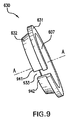
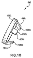
In one embodiment, the
図10および図11は、ロックリング642がリング1002から突出する3つのアーム656(別名プロング656)を有するような、ロックリング642の実施例を示す。図10はロックリング642の斜視図であり、図11はロックリング642の断面の側面図である。図10および図11に示されるように、プロング656はリング1002の一般に一方側から外向きに突出し、リングの中心の中心に向かって内向きに角度がついている。本願明細書にさらに記述するように、プラグ160がソケット158に挿入されると、ロックリング642はプラグ160を適所に「ロックする」よう機能する。
10 and 11 show an embodiment of the
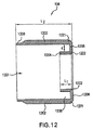
ここで図12および図13を参照して、図12はシュラウド106の断面の側面図であり、図13は、シュラウド106の断面の斜視図であって、両図ともに1つの実施例による。示されるように、シュラウド106は外壁1202、内壁1204、および内壁1204を外壁1202に接続する接続壁1206を有し得る。実施例には、壁1202、壁1204および壁1206がそれぞれリング形状で示される。この実施例では、外側リング壁1202はスペース1201を囲み、内側リング壁1204はスペース1201に配置され、外側リング壁1202と同軸である。さらに、接続壁1206は、壁1202の端部1221と壁1204の端部1222との間に接続される。壁1202、1204および1206はスペース1230を規定する。好ましくは、内壁1204の長さ(l1)は外壁1204の長さ(l2)よりも著しく小さい。
12 and 13, FIG. 12 is a cross-sectional side view of
ここで図14および図15を参照して、図14はソケット158の断面の側面図であり、図15はソケット158の斜視図であって、両図ともに1つの実施例による。示されるように、第1のハウジング102の端部部分206は、端部部分206が壁412に当接するようにキャビティ401内に配置される。したがって、第1のハウジング102の少なくとも一部分が第2のハウジング104内に収容される。
14 and 15, FIG. 14 is a cross-sectional side view of the
ハウジング104の部分402の端部464がハウジング102の遷移部分203の少なくとも一部から張り出すように、壁412から端部464までの距離は、ハウジング102の端部部分206の長さよりも長いのが好ましい。端部部分206がキャビティ401から外れるのを妨ぐために、端部464はハウジング102に向かって下向きに曲っていてもよい。
The distance from
図14にさらに示されるように、第2のハウジング104の少なくとも一部は、壁1202によって形成されるキャビティ1201内に配置される。たとえば、第2のハウジングの端部部分406および中間部分404がキャビティ1201に配置される。さらに、端部部分406の少なくとも一部およびロックリング642は、シュラウド106の壁1202、1204および1206によって形成されるスペース1230に配置される。しかしながら、突出するアーム656は、スペース1230に配置されないのが好ましい。
As further shown in FIG. 14, at least a portion of the
さらに、シュラウド106がハウジング104に固定されることが好ましい。図14に示されるように、シュラウド106は、第2のハウジングの端部部分406および中間部分404をキャビティ1201に挿入することによってハウジング104に固定されてもよく、次に、壁1202の端部部分1250を下へ折重ねて、その結果、シュラウド106が矢印Aの方向にハウジング104に相対して動かされると、折重ねられた端部部分1250は最終的に中間部分403の表面に接触し、それによりハウジング104に相対したシュラウド106のさらなる動きを防ぐ。
Further, the
好ましくは、シュラウド106は、シュラウド106がソケット158の長手軸Aと平
行な方向に「ロック解除された」位置と「ロックされた」位置との間を動くことができるように、ハウジング104に固定される。ロックされた位置では、壁1206とハウジング104の端部部分406の端部1420との間にギャップ1430があり、ロック解除された位置では、ギャップ1430は、端部1420が壁1206に当接するように、減じられるかまたは完全に取除かれる。
Preferably, the
より具体的には、ロック解除された位置では、壁1204はアーム656に接触し、アーム656を外向きに屈曲させる力をアーム656に及ぼす。たとえばアーム656aに関しては、ロック解除された位置では壁1204はアーム656aに接触し、アーム656aを矢印A11の方向に外向きに屈曲させる力を656aに及ぼす(図11および図14を参照)。シュラウド106がロック解除された位置にあるときに外力がシュラウド106に作用しなければ、シュラウド106は自動的にロックされた位置に戻る。なぜならば、アーム656の弾性により、アーム656が壁1204に対して矢印Aの方向に力を及ぼすので(図14を参照)、その力によりシュラウド106全体が矢印Aの方向にロックされた位置へ動くからである。
More specifically, in the unlocked position,
ここで図16−図18を参照して、図16はプラグ160の側面図であり、図17はプラグ160の断面の斜視図であって、図10はプラグ160の断面の側面図であり、すべての図が1つの実施例による。
16 to 18, FIG. 16 is a side view of the
図16−図18に示される1つの実施例において、プラグ160は、一般に円筒状の導電性のプラグハウジング1638を含む。図17−図18に示される1つの実施例では、プラグハウジング1638は絶縁体1740を収容し、雄型および/または雌型であり得るコンタクト1744は絶縁体1740内に固定して配置される。
In one embodiment shown in FIGS. 16-18, the
好ましくはハウジング1638は、その外壁に、その一方側に第1の傾斜面1691を有して他方側に第2の傾斜面1692を有する、突起1690を有する。突起1690はハウジング1638に対して軸方向に配置されてもよい。さらに下記に記述するように、プラグ160がソケット158に完全に挿入された後、突起1690はロックリング642とともにソケット158にプラグ160を保持するよう機能する。
Preferably,
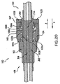
ここで図19および図20を参照して、図19および図20は、ある実施例によるソケット158に完全に挿入されたプラグ160を示す。1つの実施例において、プラグ160がソケット158に完全に挿入されると、図19および図20に示されるように、プラグコンタクト1744はソケットコンタクト304と伝導的に合わされる。示される実施例では、プラグコンタクト1744は雌型コンタクトである一方で、ソケットコンタクト304は雄型コンタクトである。代替的実施例では、プラグコンタクト1644はメス型接続端子である一方で、ソケットコンタクト310は雄型接続端子である。さらに、突起1690およびロックリング642は、ソケット158内部でプラグ160を「ロックする」ように協働する。すなわち、突起1690およびロックリング642がプラグ160の矢印Zの方向への動きを制限するので、突起1690およびロックリング642はコンタクト304とコンタクト1744とが合わなくなるのを防ぐ(図20を参照)。
Referring now to FIGS. 19 and 20, FIGS. 19 and 20 show the
示された実施例では、突起1690の傾斜面1691は、プラグ160がソケット158に挿入されるときにロックリング642の突出するアーム656と接触する、突起1690の最初の部分である。プラグ160がソケット158に押込まれるとき、アーム656がいくらか弾性なので、傾斜面1691はアーム656を外向きに動くよう付勢し、突起1690がアーム656の下を通過することを可能にする。一旦突起1690がアーム656の下を通過したならば、図19および図20に示されるように、アーム656は自動的にその本来の位置に戻る。
In the illustrated embodiment, the
アーム656がその本来の位置に戻ると、アーム656の端部1090は突起1690の表面1692に対向して位置決めされる。したがって、プラグ160を矢印Zの方向にソケット158に相対して動かすよう試みる場合、表面1692は、アーム656の端部1090と接触し、矢印Zの方向にアーム656に対して力を及ぼす。アーム656はバンド1002に接続され、バンド1002はハウジング104に固定され、それはハウジング102に固定される。したがって、アーム656は、ハウジング104に相対して矢印Zの方向に自由に動くことができない。したがって、アーム656は、表面1692上に対して等しい反対方向の力を及ぼし、それによりプラグ160が矢印Zの方向にソケット150に相対して動くことを妨げる。表面1692は、表面1692がアーム656に力を及ぼすときにアーム656が外向きに付勢されないように、ハウジング1638の外部表面に対して角度がついているのが好ましい。
When the arm 656 returns to its original position, the
シュラウド106は、ソケット158からプラグ160を取除くために、その安定した状態の「ロックしている」位置から「ロック解除された」位置に動かされる。シュラウドがロック解除された位置に動かされるためには、シュラウド106はハウジング104に相対して矢印Xの方向にある距離だけ動かされる(図19および図20を参照)。この距離は、壁1202がアーム656(たとえばアーム656a)に接触するため、また突起1690がアーム656の下を通過することができる程度にアーム656を上向きに付勢するために十分に大きい必要がある。シュラウド106がそのロック解除された位置にあるとき、プラグ160をZ方向に引っ張ることによってソケット150からプラグ160を取除くことができる。
The
図19および図20、特に接地コンタクト630を参照して、接地コンタクト630は好ましくは分離リング接地コンタクト(図9参照)であって、プラグハウジング1638の前部部分1601の外径より小さい内径を有する。したがって、この実施例において、プラグ160がソケット158に挿入されるとき、前部部分1601が胴部分632の内部表面601に接触し、胴部分632に径方向力を及ぼし、それがコンタクト630を開く(すなわち、ギャップ933をより広くする)。胴部分632は、ハウジング1638に径方向力を及ぼすことによりこの力に応答する。接地コンタクト630と導電性ハウジング1638との間のこれらの力は、コンタクト630とハウジング1638と間に十分な電気接続を生成する。
Referring to FIGS. 19 and 20, particularly
示された実施例において、ソケット158およびプラグ160は、プラグ160がソケット158に完全に挿入されるときにハウジング1638の表面1691が接地コンタクト630bの内部表面601に接触して径方向および軸方向の力を及ぼすように構成され、ギャップ933を拡大させ、コンタクト630bがハウジング1638に対して径方向および軸方向の力を及ぼすようにさせる。コンタクト630bによってハウジング1638に及ぼされる軸方向力は矢印Zの方向に及ぼされる。
In the illustrated embodiment, the
ここで図19および環状リブ422を参照して、プラグハウジング1638は、環状リブ422内に伝導的に配置され得る。1つの実施例では、環状リブ422の内径(id5)(図4参照)が、ソケット158に挿入中、円筒状のプラグハウジング1638を導くことができる。この実施例では、ハウジング1638は環状リブ422の内部にプレス嵌めされてもよい。別の実施例では、ハウジング1638はリブ422の内部に滑り嵌めされてもよい。
Referring now to FIG. 19 and the
代替的実施例
図21は、本発明の別の実施例によるスナップロック接続端子装置2100の側面図である。接続端子装置2100は第1の接続端子構成要素2158(別名「ソケット215
8」)および第2の接続端子構成要素160(別名「プラグ160」)を含む。好ましくは、図21に示されるように、ソケット2158はプラグ160を受取るように設計される。図21にさらに示されるように、ソケット2158はハウジング2102(別名「ソケット本体2102」または「本体2102」)およびシュラウド2106を含んでもよい。
Alternative Embodiment FIG. 21 is a side view of a snap lock
8 ") and a second connection terminal component 160 (also known as" plug 160 "). Preferably, as shown in FIG. 21,
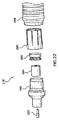
ここで図22を参照して、図22はいくつかの実施例によるソケット2158の分解図である。したがって、図22は、いくつかの実施例によるソケット2158の構成要素を示す。図22に示されるように、ソケット2158は、ハウジング2102と、内部コンタクト2204と、誘電体2204(別名「絶縁体2204」)と、外部コンタクト2206または(別名接地コンタクト2206)と、ロックリング2208と、シュラウド2106とを含む。図22は、雄型コンタクトである内部コンタクト2204を示すが、他の実施例では内部コンタクト2204は雌型コンタクトまたは他のコンタクトでもよい。他のいくつかの図面に示されるように、ハウジング2102は、絶縁体2204、内部コンタクト2202および外部コンタクト2206を収容し、ハウジング2202の前部部分はロックリング2208によって規定された後部開口部に挿入され、かつロックリング2208はシュラウド2106内に嵌合する。いくつかの実施例では、コスト削減のために、ソケットの外部コンタクト2206および/または他の構成要素は利用されなくてもよい。
Reference is now made to FIG. 22, which is an exploded view of a
ここで図23および図24を参照して、図23はハウジング2102の断面の側面図であり、図24はハウジング2102の斜視図であって、両図ともに1つの実施例による。示されるように、ハウジング2102は一般に円筒状でもよい。ハウジング2102はさらに第1の端部部分2302(すなわち点線Aの左側の部分)、第2の端部部分2306(すなわち点線Cの右側の部分)、および、端部部分2302と2306との間(すなわち点線BとCとの間の部分)に位置する中間部分2304を有し得る。各部分2302、2304および2306は外径および内径を有してキャビティを規定することができる。たとえば、端部部分2302はキャビティ2301を規定し、端部部分2306はキャビティ2311を規定する。いくつかの実施例では、外向きに延在する環状リブ2399が端部部分2306に配置される。好ましくは、リブ2399は、部分2304および2306の交点に形成された壁2398に隣接するがわずかにそこから間隔を置いて配置される。
Referring now to FIGS. 23 and 24, FIG. 23 is a cross-sectional side view of the
好ましくは、端部部分2302と中間部分2304との間に遷移部分2303が与えられる。遷移部分2303は非均一な外径を有する。図23に示されるように、その最大部では、部分2303の外径は部分2304の外径に等しいかまたはほぼ等しく、その最小部では部分2303の外径は部分2302の外径と等しいかまたはほぼ等しい。図23に示されるように、遷移部分2303は内向きに突出する環状リブ2322を含んでもよい。
Preferably, a
さらに、端部部分2306は、端部部分2391および2394、中間部分2392および2393から構成されてもよい。示されるように、端部部分2391は中間部分2391と中間部分2304との間に直接あり、中間部分2392は、端部部分2391と中間部分2393との間に直接あり、中間部分2393は、中間部分2392と端部部分2394と間に直接ある。
Further, the
図23にさらに示されるように、部分2391−2394は実質的に等しい外径を有するが内径は異なる。たとえば、示された実施例では、部分2391の内径(すなわち「id1」)は、部分2392の内径(すなわち「id2」)より小さく、id2はid3(すなわち部分2393の内径)より小さい。いくつかの実施例では、id2は、端部部分
2394の内径であるid4と等しくてもよい。id2がid1より小さいので、部分2391および2392によって壁2383が形成される。さらに、id3がid2およびid4より小さいので、部分2392および2393、2394および2393によって、壁2381および2382がそれぞれ形成される。
As further shown in FIG. 23, portions 2391-2394 have substantially equal outer diameters but different inner diameters. For example, in the illustrated example, the inner diameter of portion 2391 (ie, “id1”) is less than the inner diameter of portion 2392 (ie, “id2”), and id2 is less than id3 (ie, the inner diameter of portion 2393). In some embodiments, id2 may be equal to id4, which is the inner diameter of
図34に関してさらに本願明細書に説明されるように、壁2383は、プラグ160がソケット2158に差し込まれるとき、プラグ160の動きを停止するストッパとして機能することができる。すなわち、いくつかの実施例では、プラグ160がソケット2158に差し込まれるときプラグ160の先端が壁2383と接触するように(たとえば図34参照)、id1はプラグ160の外径より小さい一方でid2はプラグ160の外径より大きく、それによりプラグ160の前向きの動きが止められる。
As further described herein with respect to FIG. 34, the
ここで図25を参照して、図25は、ハウジング2102に収容された絶縁体2204およびコンタクト2202を示す。示された実施例では、コンタクト2202は細長く、かつ絶縁体2204の長手軸およびハウジング2102の長手軸と位置合わせされる長手軸を有する。絶縁体2204は、コンタクト2202の少なくとも一部を囲み、電気的に導電性であるコンタクトをハウジング2102から電気的に絶縁するよう機能する。絶縁体2204は、絶縁体2204の端部2501が環状リブ2232に当接するかまたは隣接するよう、かつ反対端部2502が壁2383と実質的に同一平面上にあるようにハウジング2102内に位置決めされる。
Referring now to FIG. 25, FIG. 25 shows an
図25はさらに、ハウジング2102に収容される外部コンタクト2206を示す。より具体的には、示された実施例では、外部コンタクト2206は、中間部分2393を境界して規定する環状の壁2381と2382との間に配置されて保持される。1つの実施例による外部コンタクト2206は図26にさらに示される。
FIG. 25 further shows an
図26は1つの実施例によるコンタクト2206の斜視図である。示されるように、コンタクト2206は(たとえばリング状に形成された)環状でもよい。示された特定の実施例では、コンタクト2206は、分離リングである(すなわち、コンタクト2206は一般にリング形状で、コンタクト2206の両端間にギャップ2699を有する)。示された特定の実施例では、コンタクト2206は第1の分離リング2601と、第2の分離リング2602と、1つ以上の一般にU形状の、第1のリング2601を第2のリング2602に接続するコンタクト2604とを含む。示された実施例では、リング2601および2602は実質的に等しい内径および外径を有するが、リング2601の幅はリング2602の幅よりも実質的に大きい。さらに、示されるように、リング2601および2602は同軸になる(たとえば共通の中心軸Aを共有する)よう好ましくは配列され、一般にU形状のコンタクト2604は中心軸Aに向かって内向きに湾曲する。
FIG. 26 is a perspective view of a
図25を参照して、コンタクト2206は、壁2381および2382ならびに部分2393の内壁によって規定される環状溝2387内に堅く保持される。さらに、コンタクト2206はハウジング2102と同軸になるよう配列される。すなわち、コンタクトとハウジングとが共通の中心軸を有する。
Referring to FIG. 25,
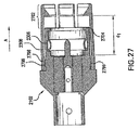
ここで図27を参照して、図27は部分的に組立てられたソケット2158の断面の側面図である。図27は、ロックリング2208の近位端に挿入されたハウジング2102の端部部分2306を示す。示されるように、端部部分がロックリング2208に完全に挿入されるとき、ロックリング2208の前部部分2702が端部部分2306の端部2704を越えて延在するように、部分2306の長さはロックリング2208の長さより小さい。図27に示されるように、ロックリング2208の近位端の内径は部分2306の外径よりわずかに大きく、そのためそれらが合わさると構成要素間にとまり嵌め(snug
fit)を生成する。
Referring now to FIG. 27, FIG. 27 is a cross-sectional side view of a partially assembled
fit).
好ましくは、図27に示されるようにハウジング2102とロックリング2208とが合わさるとき、ロックリング2208は、著しい力が矢印Aの方向にロックリング2208に対して及ぼされるときにさえ、ロックリング2208が矢印Aの方向に動くことができないように、ハウジング2102に固定される。この目的のために、環状リブ2399(図23参照)が与えられてもよい。すなわち、ロックリング2208がハウジング2102とロックリング2208とが完全に合わされた後に矢印Aの方向に動くことができるのを妨げるか、妨げるのを助けるために、環状リブ2399が使用されてもよい。さらに、ロックリング2208は、ロックリング2208のベースリング2798部分の内部表面から突出するタブ2799を有していてもよく、そのタブは環状リブ2399と協働してロックリング2208をハウジング2102に固定する。
Preferably, when the
ここで図28を参照して、図28は1つの実施例によるロックリング2208をさらに示す。示された実施例では、ロックリング2208はベースリング2798と、ベースリング2798に取付けられた1つ以上のフィンガ部2804を含む。フィンガ部2804は、ベースリング2798およびフィンガ部2804が単一のユニットを形成するように、ベースリング2798に一体的に取付けられてもよい。示されるように、フィンガ部2804は、ベースリング2798の中心軸2890と同じ一般的方向に延在する。すなわちいくつかの実施例では、各フィンガ部2804の長手軸は、ベースリング2798の中心軸2890とほぼ平行である(しかし正確に平行ではない)。たとえば、1つの特定の実施例では、各フィンガ部2804の長手軸とロックリング2208の中心軸2890との間には約2度の角度がある。好ましくは、2つ以上のフィンガ部2804がある実施例では、フィンガ部2804は、ベースリング2798のまわりに規則的な角度間隔で配列される。
Referring now to FIG. 28, FIG. 28 further illustrates a
ここで図29および図30を参照して、図29はロックリング2208の断面図であり、図30はロックリング2208のフィンガ部2804の1つの断面図である。図29に示されるように、フィンガ部2804は規則的な角度間隔でベースリング2798のまわりに配列され、各フィンガ部はベースリング2798に接続された近位端2902および対向する遠位端または「先端」2904を有する。図30に示されるように、いくつかの実施例において、ロックタブ3002が遠位端2904から内向きに間隔を置いて配置され、フィンガ部2804の内部表面3001からロックリング2208の中心軸に向かって突出している。
Referring now to FIGS. 29 and 30, FIG. 29 is a cross-sectional view of the
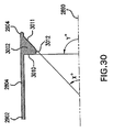
図30に示される実施例では、ロックタブ3002は近位端2902に一般に対面する平坦な後部壁3010と遠位端2904に一般に対面する平坦な前部壁とを有する。後部壁3010は、ロックリング2208の中心軸2890と角度Yを形成する平面上にある。1つの実施例では、示されるように角度Yは90度かそのあたりである。前部壁3011は後部壁3010に向かって角度を有し、ロックリング2208の中心軸2890と角度Xを形成する平面上にある。1つの実施例では、角度Xは20から60度かそのあたりである。1つの特定の実施例では、角度Xは約36度である。丸みのある底部壁3012は、前部壁3011と後部壁3010を接続する。
In the embodiment shown in FIG. 30, the
ここで図31および図32を参照して、図31はシュラウド2106の断面の側面図であり、図32はシュラウド2106の断面の斜視図であって、両図ともに1つの実施例による。示されるように、シュラウド2106は外壁または「外部スリーブ」3102と、内壁または「内部スリーブ」3104と、内壁3104を外壁3102に接続する接続部材3106とを有し得る。示される実施例では壁3102および3104は各々リング形状である。この実施例では、外側リング壁3102はスペース3190を囲み、内側リン
グ壁3104はスペース3190に配置されて外側リング壁3102と同軸である。さらに、接続部材3106は、壁3102の端部と端壁3104との間に接続される。壁3102および3104ならびに部材3106はスペース3130を規定する。好ましくは、内壁3104の長さ(L1)は外壁3102の長さ(L2)よりも著しく小さい。
Referring now to FIGS. 31 and 32, FIG. 31 is a cross-sectional side view of
内壁3104は、内側3170および外側3171の2つの主な側を有する。壁3104の内側3170は開口部3199を規定する。図31に示されるように、いくつかの実施例で2つの側が環状の尾根部3175を形成するために集束するよう、外側3171は内側3170に対して平行ではない。
The
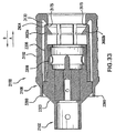
ここで図33を参照して、図33は1つの実施例によるソケット2158の完全に組立てられた後の断面の側面図である。図33に示されるように、ソケット2158が完全に組立てられると、ハウジング2102の端部部分2306はロックリング2208に挿入され、次にその構成要素のアセンブリはシュラウド2106に挿入されて、その結果シュラウドが端部2306およびロックリング2208を囲む。
Referring now to FIG. 33, FIG. 33 is a cross-sectional side view after the
シュラウド2106がハウジング2102に固定されることが好ましい。シュラウド2106は、図33に示されるように、端部部分2306をシュラウド2106に挿入して、次に壁3102の端部3390を折曲げることによりハウジング2102に固定されてもよく、その結果、シュラウド2106がハウジング2102に相対して図33の矢印Aの方向に動くときに、折曲げられた端部部分3390が結局はハウジング2102の遷移部分2303の表面と接触し、それによってハウジング2102に相対したシュラウド2106の矢印A方向へのさらなる動きを防ぐ。
A
好ましくは、シュラウド2106は、シュラウド2106がソケット2158の長手軸と平行な方向に「ロックを解除された」位置と「ロックされた」位置との間を動くことができるように、ハウジング2102に固定される。ロック解除された位置にシュラウド2106を位置決めするために、シュラウド2106は矢印B方向に動かされ、その結果尾根部3175がフィンガ部2804のロックタブ3002の表面3011に対して接触して押圧し、それによってフィンガ部2804に力を及ぼし、その力がフィンガ部2804を外向きに屈曲させる。
Preferably,
ロック解除された位置にシュラウドを位置決めするために、シュラウドは、尾根部3175がフィンガ部2804に対して全く、または有意の外力を及ぼさない程度にまでロックリング2208に相対して矢印Aの方向に動かされる。図33は、ロックされた位置に位置決めされたシュラウド2106を示す。図33に示されるように、この実施例では、尾根部3175はロックタブ3002の表面3011に対して押圧するのではなく、むしろフィンガ部2804の先端2904に接触するかまたは隣接する。スペース3130は、シュラウド2106がロック解除された位置に動かされるときに先端2904を受取るよう構成されることに注意されるべきである。
To position the shroud in the unlocked position, the shroud is in the direction of arrow A relative to the
シュラウド2106がロック解除された位置にあるとき、外力がシュラウド2106に作用しなければ、シュラウド2106はロックされた位置に自動的に戻る。なぜならばフィンガ部2804の弾性により、フィンガ部2804が、矢印Aの方向にシュラウド2106に対して力を及ぼすからであり、その力がシュラウド2106を矢印Aの方向にロックされた位置まで動くようにする。
When the
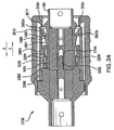
ここで図34を参照して、図34は、ある実施例によるソケット2158に完全に挿入されたプラグ160を示す。1つの実施例では、図34に示されるように、プラグ160がソケット2158に完全に挿入される時、プラグコンタクト1744が伝導的にソケッ
トコンタクト2202と合わさる。示された実施例では、プラグコンタクト1744が雌型コンタクトである一方で、ソケットコンタクト2202は雄型コンタクトである。1つの代替実施例では、プラグコンタクト1644は雌型コンタクトである一方で、ソケットコンタクト310は雄型コンタクトである。さらに、突起1690およびロックリング2208のフィンガ部2804は、ソケット2158の内部でプラグ160を「ロックする」ように協働する。すなわち、突起1690およびロックリング2208は、突起1690およびロックリング2208がプラグ160の矢印Zの方向への動きを制限するので、コンタクト2202および1744が合わなくなることを防ぐ。
Reference is now made to FIG. 34, which shows the
示された実施例では、プラグ160がソケット2158に挿入されるとき、突起1690の傾斜面1691は、フィンガ部2804のロックタブ3002と接触する突起1690の最初の部分である。フィンガ部2804がいくらか弾性なので、プラグ160がソケット2158に押込まれるとき、傾斜面1691がフィンガ部2804の表面3011に対して押圧し、それによってフィンガ部2804が外向きに動くようにし、突起1690がロックタブ3002の下を通過することを可能にする(ロックタブ3002aおよび3002bは図34に示される)。一旦突起1690がフィンガ部2804のロックタブ3002の下を通過したならば、図34に示されるように、フィンガ部2804は自動的にその本来の位置に戻る。
In the illustrated embodiment, the
フィンガ部2804がその本来の位置に戻るとき、各フィンガ部2804の後部壁3010は突起1690の表面1692に対向しかつ対面して位置決めされる。このように、プラグ160を矢印Zの方向にソケット2158に相対して動かすことを試みた場合、表面1692は各フィンガ部2804の後部壁3010に接触し、矢印Zの方向に力を及ぼす。好ましい実施例では、壁3010は、表面1692に対して実質的に等しい、対向する力を及ぼす。なぜならば、上述されたように、好ましくはロックリング2208はハウジング2102に固定されるからである。したがって、シュラウド2106がロック解除された位置にあるのでなければ、矢印Zの方向にプラグ160を押したり引いたりすることによっては、(ほとんどの場合)ソケット2158からプラグ160を取除くことにならない。すなわち、シュラウド2106がロックされた位置にある場合、プラグ160に対する大きな引く/押す力だけがソケット2158からプラグ160を係合解除する。
When the
したがって、ソケット2158からプラグ160を取除くためには、シュラウド2106をその安定した状態であるロックされた位置からロック解除された位置に動かすことになる。上述にように、シュラウドをロック解除された位置に動かすためには、シュラウド2106はハウジング2102に相対して矢印Xの方向にある距離だけ動かされる(図34を参照)。この距離は、内部スリーブ3104がフィンガ部2804のロックテーブル3002に接触して押圧するほど十分に大きい必要があり、それによって、突起1690がロックタブ3002の下を通過することができる程度にまで、フィンガ部2804を上向きに付勢する。シュラウド2106がそのロック解除された位置にあるとき、最小限の量の力でZ方向にプラグ160を引っ張ることにより、ソケット150からプラグ160を取除くことができる。
Thus, to remove the
図34および特にコンタクト2206を参照して、コンタクト2206は好ましくは分離リングである(図26参照)。プラグ160がソケット158に挿入されるとき、前部部分1601の少なくとも一部がコンタクト2206の内部表面と接触し、その部分がコンタクト2206を開くようにする(すなわち、ギャップ2699をより広くする)径方向力をコンタクト2206に及ぼす。コンタクト2206は、ハウジング1638に径方向力を及ぼすことによりこの力に応答する。接地コンタクト2206と導電性ハウジング1638の間のこの力は、コンタクト2206とハウジング1638との間に十分な電気接続を生成する。示された特定の実施例では、前部部分1601の少なくとも一部がU形
状のコンタクト2604の内部表面と接触するが、分離リング2601または2602といずれとも接触しない。
Referring to FIG. 34 and particularly
図34に示される実施例に示されるように、壁2383からロックタブ3002の後部壁3010までの距離(d1−図27参照)は、プラグ160の前部端部から突起1690の表面1692の底の点への距離(d2−図18参照)に等しいかまたはほぼ等しい。したがって、示された実施例において、壁2383は、プラグがどれくらい深くソケット2158に挿入できるかを制限するストッパとして機能する。
As shown in the embodiment shown in FIG. 34, the distance from the
ここで図35を参照して、図35は別の実施例によるスナップロック接続端子装置3500の断面の側面図である。接続端子装置は接続端子装置2100に類似している。図35に示されるように、接続端子装置3500と装置2100との主な差は、プラグ160がソケット2158の遠位端に挿入されてロックリング2208によってソケット2158内にロックされるとき、プラグハウジング1638の前部部分1601の先端3533がハウジング2102の壁2383と接触しないことである。すなわち、代替的実施例では、プラグ160がソケット2158内に完全に挿入されロックされるとき、先端3533と壁2383との間にギャップが存在する。いくつかの実施例では、ギャップの幅は少なくとも約0.005インチである。
Referring now to FIG. 35, FIG. 35 is a cross-sectional side view of a snap lock
したがって、代替的実施例では、プラグ160がフィンガ部2804によってソケット2158内にロックされるとき、フィンガ部2804が突起1690に対して押圧することによりプラグ160に軸方向力を及ぼすことができるが、軸方向力はプラグ160の前部表面3533が壁2383を押圧するようにしない。
Thus, in an alternative embodiment, when the
本発明のさまざまな実施例/変形が上述されたが、限定ではなく単に実施例として示されたことが理解されなければならない。したがって、本発明の幅および範囲は、上記の例示的な実施例のうちのいずれによっても限定的であるべきでないが、以下の請求項およびそらの等価物にしたがってのみ規定されるべきである。 While various embodiments / variations of the invention have been described above, it should be understood that they have been presented by way of example only and not limitation. Accordingly, the breadth and scope of the present invention should not be limited by any of the above-described exemplary embodiments, but should be defined only in accordance with the following claims and their equivalents.
Claims (35)
ソケットを含み、ソケットは、
ソケットハウジングと、
前記ソケットハウジング内に配置された絶縁体と、
前記絶縁体内に配置された第1のコンタクトと、
前記ハウジングの遠位端のまわりに配置されたロックリングと、
前記ソケットハウジングの前記遠位端および前記ロックリングのまわりに配置されて前記ソケットハウジングに相対して第1の位置および第2の位置の間で移動可能なシュラウドとを含み、前記シュラウドは外壁および内壁を有し、前記シュラウドおよび前記ロックリングは、前記シュラウドが前記第1の位置から前記第2の位置に動くとき、前記内壁は前記ロックリングに接触して前記ロックリングを外向きに屈曲させるよう構成され、前記接続子装置はさらに、
プラグを含み、プラグは、
絶縁体および絶縁体内に配置されたコンタクトを収容する一般に円筒状の導電性プラグハウジングを含み、プラグハウジングは、その外壁に、一方側に第1の傾斜面を有して反対側に第2の傾斜面を有する突起を有し、
ソケットは、プラグがソケットの遠位端に挿入されてロックリングによって定位置にロックされると、ロックリングがプラグハウジングの突起に軸方向力を及ぼすように構成されるが、この軸方向力は、プラグハウジングの前部表面がソケットのいずれの表面も押圧するようにはしない、装置。 A connection terminal device,
Including sockets, sockets
A socket housing;
An insulator disposed within the socket housing;
A first contact disposed within the insulator;
A lock ring disposed around a distal end of the housing;
A shroud disposed about the distal end of the socket housing and the lock ring and movable between a first position and a second position relative to the socket housing, the shroud comprising an outer wall and The shroud and the lock ring have an inner wall, and when the shroud moves from the first position to the second position, the inner wall contacts the lock ring and bends the lock ring outward. The connector device is further configured as follows:
Including plugs,
A generally cylindrical conductive plug housing containing an insulator and a contact disposed within the insulator, the plug housing having a first inclined surface on one side and a second on the opposite side on the outer wall thereof. Having a protrusion having an inclined surface;
The socket is configured such that when the plug is inserted into the distal end of the socket and locked in place by the lock ring, the lock ring exerts an axial force on the protrusion of the plug housing. The device does not allow the front surface of the plug housing to press any surface of the socket.
ィンガはベースリングの中心軸と同じ一般的な方向に延在する、請求項1に記載の装置。 The apparatus of claim 1, wherein the lock ring includes a base ring and fingers attached to the base ring, the fingers extending in the same general direction as the central axis of the base ring.
ハウジングと、
前記ハウジング内に配置された絶縁体と、
前記絶縁体内に配置された第1のコンタクトと、
ハウジングの内部表面に位置する環状溝内に収容された環状の接地コンタクトと、
前記ハウジングの遠位端のまわりに配置されたロックリングと、
前記ハウジングの前記遠位端および前記ロックリングのまわりに配置されて前記ハウジングに相対して第1の位置および第2の位置の間で移動可能なシュラウドとを含み、前記シュラウドは外壁および内壁を有し、前記シュラウドおよび前記ロックリングは、前記シュラウドが前記第1の位置から前記第2の位置に動くとき、前記内壁が前記ロックリングに接触して前記ロックリングを外向きに屈曲させるよう構成される、ソケット。 A socket,
A housing;
An insulator disposed within the housing;
A first contact disposed within the insulator;
An annular ground contact housed in an annular groove located on the inner surface of the housing;
A lock ring disposed around a distal end of the housing;
A shroud disposed about the distal end of the housing and the lock ring and movable between a first position and a second position relative to the housing, the shroud comprising an outer wall and an inner wall. The shroud and the lock ring are configured such that when the shroud moves from the first position to the second position, the inner wall contacts the lock ring and bends the lock ring outward. Socket.
第1の分離リングと、
第2の分離リングと、
第1の分離リングを第2の分離リングと接続する1つ以上の一般にU形状のコンタクトとを含み、
分離リングは同軸になるよう配列される、接地コンタクト。 A ground contact used to establish an electrical connection between the socket housing and the plug housing,
A first separation ring;
A second separation ring;
One or more generally U-shaped contacts connecting the first isolation ring with the second isolation ring;
A ground contact, where the isolation rings are arranged coaxially.
Applications Claiming Priority (4)
| Application Number | Priority Date | Filing Date | Title |
|---|---|---|---|
| US65163705P | 2005-02-11 | 2005-02-11 | |
| US70030905P | 2005-07-19 | 2005-07-19 | |
| US11/296,336 US7189097B2 (en) | 2005-02-11 | 2005-12-08 | Snap lock connector |
| PCT/US2006/003380 WO2006088639A1 (en) | 2005-02-11 | 2006-02-01 | Snap lock connector |
Publications (2)
| Publication Number | Publication Date |
|---|---|
| JP2008530754A true JP2008530754A (en) | 2008-08-07 |
| JP2008530754A5 JP2008530754A5 (en) | 2009-01-29 |
Family
ID=36816237
Family Applications (1)
| Application Number | Title | Priority Date | Filing Date |
|---|---|---|---|
| JP2007555127A Pending JP2008530754A (en) | 2005-02-11 | 2006-02-01 | Snap lock connection terminal |
Country Status (8)
| Country | Link |
|---|---|
| US (2) | US7189097B2 (en) |
| EP (1) | EP1846988A4 (en) |
| JP (1) | JP2008530754A (en) |
| KR (1) | KR101160322B1 (en) |
| CN (1) | CN101116228B (en) |
| AU (1) | AU2006214647C1 (en) |
| CA (1) | CA2597664C (en) |
| WO (1) | WO2006088639A1 (en) |
Cited By (2)
| Publication number | Priority date | Publication date | Assignee | Title |
|---|---|---|---|---|
| JP2009032587A (en) * | 2007-07-27 | 2009-02-12 | Tyco Electronics Amp Kk | Electrical connector and connector assembly |
| JP2015506500A (en) * | 2012-01-25 | 2015-03-02 | ハルティング エレクトロニクス ゲゼルシャフト ミット ベシュレンクテル ハフツングHARTING Electronics GmbH | Plug-in connection system for plug-in connectors |
Families Citing this family (79)
| Publication number | Priority date | Publication date | Assignee | Title |
|---|---|---|---|---|
| US7090516B2 (en) * | 2004-02-09 | 2006-08-15 | Adc Telecommunications, Inc. | Protective boot and universal cap |
| US7114990B2 (en) | 2005-01-25 | 2006-10-03 | Corning Gilbert Incorporated | Coaxial cable connector with grounding member |
| EP2016649B1 (en) * | 2006-05-08 | 2012-07-25 | Multi-Holding AG | Plug connector |
| CN200959447Y (en) * | 2006-08-15 | 2007-10-10 | 富士康(昆山)电脑接插件有限公司 | Electric-connector assembly |
| US8109883B2 (en) | 2006-09-28 | 2012-02-07 | Tyco Healthcare Group Lp | Cable monitoring apparatus |
| CN2896603Y (en) * | 2006-09-29 | 2007-05-02 | 瞿金良 | Fast-plugging self-locking type radio coaxial connector |
| US7727012B2 (en) * | 2006-10-26 | 2010-06-01 | John Mezzalingua Associates, Inc. | Radial and thrust snap bearing retainer |
| US8668651B2 (en) | 2006-12-05 | 2014-03-11 | Covidien Lp | ECG lead set and ECG adapter system |
| US7466288B2 (en) * | 2007-03-15 | 2008-12-16 | Chung-Chuan Huang | Combination of antenna terminal and reception member |
| CN101657749B (en) | 2007-04-20 | 2014-01-01 | 胡贝尔和茹纳股份公司 | Optical connector |
| CA2646037C (en) | 2007-12-11 | 2017-11-28 | Tyco Healthcare Group Lp | Ecg electrode connector |
| PE20091269A1 (en) | 2007-12-14 | 2009-09-09 | Medarex Inc | BINDING MOLECULES TO THE HUMAN OX40 RECEIVER |
| US7857651B2 (en) * | 2008-06-04 | 2010-12-28 | Hon Hai Precision Ind. Co., Ltd | Coxial connector having resilient ring and sealing ring |
| SI2133958T1 (en) * | 2008-06-09 | 2011-06-30 | Interlemo Holding Sa | Female plug for self-locking connector system |
| US7722379B2 (en) * | 2008-07-30 | 2010-05-25 | Aliner Industries, Inc. | Quick release connector device |
| US8113875B2 (en) | 2008-09-30 | 2012-02-14 | Belden Inc. | Cable connector |
| USD737979S1 (en) | 2008-12-09 | 2015-09-01 | Covidien Lp | ECG electrode connector |
| US8215884B2 (en) * | 2008-12-16 | 2012-07-10 | Lockheed Martin Corporation | Connector for use in high vibration environment |
| US8496495B2 (en) * | 2009-06-01 | 2013-07-30 | Emerson Network Power Connectivity Solutions, Inc. | Coaxial connector with coupling spring |
| US7758370B1 (en) * | 2009-06-26 | 2010-07-20 | Corning Gilbert Inc. | Quick release electrical connector |
| US8694080B2 (en) | 2009-10-21 | 2014-04-08 | Covidien Lp | ECG lead system |
| JPWO2011058649A1 (en) * | 2009-11-13 | 2013-03-28 | 株式会社ジョイン | connector |
| WO2011083391A2 (en) | 2010-01-05 | 2011-07-14 | Pfizer Inc. | Biomarkers for anti-igf-ir cancer therapy |
| JP5826247B2 (en) * | 2010-04-09 | 2015-12-02 | エフシーアイ・オートモティヴ・ホールディング | Electromagnetic shield device |
| US7938680B1 (en) * | 2010-04-13 | 2011-05-10 | Ezconn Corporation | Grounding electrical connector |
| TWI549386B (en) | 2010-04-13 | 2016-09-11 | 康寧吉伯特公司 | Coaxial connector with inhibited ingress and improved grounding |
| CN101872927B (en) * | 2010-06-22 | 2013-06-19 | 中航光电科技股份有限公司 | Direct-breakoff type electric connector and plug thereof |
| CN101950897B (en) * | 2010-07-19 | 2013-03-27 | 中航光电科技股份有限公司 | Direct breakoff electric connector assembly and plug thereof |
| CA2746944C (en) | 2010-07-29 | 2018-09-25 | Tyco Healthcare Group Lp | Ecg adapter system and method |
| CH703474A2 (en) * | 2010-07-30 | 2012-01-31 | Huber+Suhner Ag | Coaxial connector. |
| US8888526B2 (en) | 2010-08-10 | 2014-11-18 | Corning Gilbert, Inc. | Coaxial cable connector with radio frequency interference and grounding shield |
| WO2012032433A1 (en) | 2010-09-09 | 2012-03-15 | Pfizer Inc. | 4-1bb binding molecules |
| GB2483498A (en) * | 2010-09-10 | 2012-03-14 | Miniflex Ltd | A water-resistant optical fibre connector with an elastomer sleeve providing both a water seal and a coupling force |
| DE102010042354A1 (en) | 2010-10-12 | 2012-04-12 | Intercontec Pfeiffer Gmbh | Electrical connector with a tear-off and method for reversibly connecting and disconnecting male parts of a connector |
| TWI558022B (en) | 2010-10-27 | 2016-11-11 | 康寧吉伯特公司 | Push-on cable connector with a coupler and retention and release mechanism |
| US8157588B1 (en) | 2011-02-08 | 2012-04-17 | Belden Inc. | Cable connector with biasing element |
| KR101122551B1 (en) * | 2011-04-18 | 2012-03-20 | 남부대학교산학협력단 | Solar connector |
| CN103687537B (en) | 2011-07-22 | 2016-02-24 | 柯惠有限合伙公司 | Ecg electrode connector |
| US9190744B2 (en) | 2011-09-14 | 2015-11-17 | Corning Optical Communications Rf Llc | Coaxial cable connector with radio frequency interference and grounding shield |
| US20130072057A1 (en) | 2011-09-15 | 2013-03-21 | Donald Andrew Burris | Coaxial cable connector with integral radio frequency interference and grounding shield |
| GB201116092D0 (en) | 2011-09-16 | 2011-11-02 | Bioceros B V | Antibodies and uses thereof |
| US8634901B2 (en) | 2011-09-30 | 2014-01-21 | Covidien Lp | ECG leadwire system with noise suppression and related methods |
| US9147955B2 (en) * | 2011-11-02 | 2015-09-29 | Ppc Broadband, Inc. | Continuity providing port |
| US8915753B2 (en) * | 2011-12-12 | 2014-12-23 | Holland Electronics, Llc | Signal continuity connector |
| DE102011056466A1 (en) * | 2011-12-15 | 2013-06-20 | Telegärtner Karl Gärtner GmbH | Coaxial connector arrangement |
| US9136654B2 (en) | 2012-01-05 | 2015-09-15 | Corning Gilbert, Inc. | Quick mount connector for a coaxial cable |
| US9407016B2 (en) | 2012-02-22 | 2016-08-02 | Corning Optical Communications Rf Llc | Coaxial cable connector with integral continuity contacting portion |
| PE20142406A1 (en) | 2012-05-04 | 2015-01-23 | Pfizer | ANTIGENS ASSOCIATED WITH PROSTATE AND VACCINE-BASED IMMUNOTHERAPY REGIMES |
| US9287659B2 (en) | 2012-10-16 | 2016-03-15 | Corning Optical Communications Rf Llc | Coaxial cable connector with integral RFI protection |
| US9147963B2 (en) | 2012-11-29 | 2015-09-29 | Corning Gilbert Inc. | Hardline coaxial connector with a locking ferrule |
| US9153911B2 (en) | 2013-02-19 | 2015-10-06 | Corning Gilbert Inc. | Coaxial cable continuity connector |
| US8801453B1 (en) | 2013-02-21 | 2014-08-12 | Bourns, Inc. | Rotary connector having a housing and a locking ring |
| EP2967396B1 (en) | 2013-03-15 | 2019-02-13 | Kpr U.S., Llc | Electrode connector with a conductive member |
| US9172154B2 (en) | 2013-03-15 | 2015-10-27 | Corning Gilbert Inc. | Coaxial cable connector with integral RFI protection |
| US9408546B2 (en) | 2013-03-15 | 2016-08-09 | Covidien Lp | Radiolucent ECG electrode system |
| USD771818S1 (en) | 2013-03-15 | 2016-11-15 | Covidien Lp | ECG electrode connector |
| EA201591495A1 (en) | 2013-03-18 | 2016-05-31 | Биосерокс Продактс Б.В. | HUMANIZED ANTIBODIES AGAINST CD134 (OX40) AND APPLICATIONS OF THE SPECIFIED ANTIBODIES |
| US10290958B2 (en) | 2013-04-29 | 2019-05-14 | Corning Optical Communications Rf Llc | Coaxial cable connector with integral RFI protection and biasing ring |
| WO2014189718A1 (en) | 2013-05-20 | 2014-11-27 | Corning Optical Communications Rf Llc | Coaxial cable connector with integral rfi protection |
| US9548557B2 (en) | 2013-06-26 | 2017-01-17 | Corning Optical Communications LLC | Connector assemblies and methods of manufacture |
| CN103401099B (en) * | 2013-08-06 | 2015-10-14 | 临沂市海纳电子有限公司 | A kind of connector with shielding contact spring |
| US9048599B2 (en) | 2013-10-28 | 2015-06-02 | Corning Gilbert Inc. | Coaxial cable connector having a gripping member with a notch and disposed inside a shell |
| US9548572B2 (en) | 2014-11-03 | 2017-01-17 | Corning Optical Communications LLC | Coaxial cable connector having a coupler and a post with a contacting portion and a shoulder |
| US9590287B2 (en) | 2015-02-20 | 2017-03-07 | Corning Optical Communications Rf Llc | Surge protected coaxial termination |
| US10033122B2 (en) | 2015-02-20 | 2018-07-24 | Corning Optical Communications Rf Llc | Cable or conduit connector with jacket retention feature |
| ES2583636B1 (en) | 2015-03-20 | 2017-06-29 | Te Connectivity Amp España, S.L.U. | Connector with detachable link box |
| ES2584540B1 (en) | 2015-03-27 | 2017-07-05 | Te Connectivity Amp España, S.L.U. | Latch for telecommunications connector |
| US10630034B2 (en) | 2015-05-27 | 2020-04-21 | Amphenol Corporation | Integrated antenna unit with blind mate interconnect |
| DE102015113086B4 (en) * | 2015-08-07 | 2020-04-09 | Norma Germany Gmbh | Connector device with cable connector and wind protection cover |
| US10211547B2 (en) | 2015-09-03 | 2019-02-19 | Corning Optical Communications Rf Llc | Coaxial cable connector |
| US9525220B1 (en) | 2015-11-25 | 2016-12-20 | Corning Optical Communications LLC | Coaxial cable connector |
| DE102016111458B4 (en) | 2016-06-22 | 2018-12-06 | HARTING Electronics GmbH | Connectors |
| EP3497754A4 (en) | 2016-08-15 | 2020-03-18 | Commscope Technologies LLC | Connector assembly with grounding |
| CN108110514A (en) * | 2016-11-24 | 2018-06-01 | 周利明 | Socket, plug and electric connection structure |
| US10950994B2 (en) * | 2017-03-10 | 2021-03-16 | John Mezzalinguaassociates, Llc | Quick connect/disconnect coaxial cable connector |
| WO2018236875A1 (en) | 2017-06-19 | 2018-12-27 | Commscope Technologies Llc | High density bezel for patch panel |
| EP3707915B1 (en) | 2017-11-10 | 2023-09-13 | Commscope Technologies LLC | Telecommunications panel with grounding wire |
| CN109638536A (en) * | 2018-11-30 | 2019-04-16 | 中航光电科技股份有限公司 | A kind of connector assembly |
| CN110265819A (en) * | 2019-07-05 | 2019-09-20 | 上海航天科工电器研究院有限公司 | A kind of fixed device of radio frequency (RF) coaxial connector |
Citations (6)
| Publication number | Priority date | Publication date | Assignee | Title |
|---|---|---|---|---|
| JPS5965489U (en) * | 1982-10-25 | 1984-05-01 | 富士通株式会社 | coaxial connector |
| JPH08227755A (en) * | 1995-02-21 | 1996-09-03 | Sumitomo Wiring Syst Ltd | Connecting structure of connector |
| US6132234A (en) * | 1995-11-20 | 2000-10-17 | Wilheilm Sihn, Jr., Kg | Coaxial plug connector for communications technology, in particular in motor vehicles |
| JP2001110522A (en) * | 1999-10-05 | 2001-04-20 | Ryosei Electro-Circuit Systems Ltd | Lock structure of connector |
| JP2001313122A (en) * | 2000-03-31 | 2001-11-09 | Tektronix Inc | Adapter for electronic connector assembly |
| US20040248459A1 (en) * | 2003-06-05 | 2004-12-09 | Fci Americas Technology, Inc. | Electrical connector with connector position assurance member |
Family Cites Families (48)
| Publication number | Priority date | Publication date | Assignee | Title |
|---|---|---|---|---|
| US2711524A (en) * | 1952-10-08 | 1955-06-21 | American Phenolic Corp | Electrical contact |
| US2785384A (en) | 1955-02-23 | 1957-03-12 | Liquidometer Corp | Moisture proof means for connecting a coaxial cable to a fitting |
| US3193309A (en) | 1961-02-13 | 1965-07-06 | Morris Arthur | Tubular connector having spring retaining means |
| US3161451A (en) | 1961-08-16 | 1964-12-15 | Multi Contact Neidecker & Co | Self-locking electric plug-and-jack connector |
| FR2204331A5 (en) | 1972-10-24 | 1974-05-17 | Radiall Sa | |
| DE2421321C3 (en) | 1974-05-02 | 1978-05-11 | Georg Dipl.-Ing. Dr.-Ing. 8152 Feldkirchen-Westerham Spinner | Sealed coaxial connector |
| US4012105A (en) | 1974-09-30 | 1977-03-15 | Bell Industries, Inc. | Coaxial electrical connector |
| US4017139A (en) | 1976-06-04 | 1977-04-12 | Sealectro Corporation | Positive locking electrical connector |
| CA1070792A (en) | 1976-07-26 | 1980-01-29 | Earl A. Cooper | Electrical connector and frequency shielding means therefor and method of making same |
| US4165911A (en) | 1977-10-25 | 1979-08-28 | Amp Incorporated | Rotating collar lock connector for a coaxial cable |
| US4239318A (en) * | 1979-07-23 | 1980-12-16 | International Telephone And Telegraph Corporation | Electrical connector shield |
| US4326768A (en) | 1980-06-02 | 1982-04-27 | The Bendix Corporation | Electrical connector grounding strap connection |
| DE3117320C2 (en) | 1980-10-15 | 1984-10-31 | Siemens AG, 1000 Berlin und 8000 München | Angled coaxial connector |
| US4426127A (en) | 1981-11-23 | 1984-01-17 | Omni Spectra, Inc. | Coaxial connector assembly |
| US4428639A (en) * | 1982-04-05 | 1984-01-31 | The Bendix Corporation | Electrical connector |
| US4674809A (en) | 1986-01-30 | 1987-06-23 | Amp Incorporated | Filtered triax connector |
| US4666231A (en) | 1986-06-26 | 1987-05-19 | Amp Incorporated | Switching coaxial connector |
| GB2207298B (en) | 1987-07-15 | 1991-06-19 | Amphenol Ltd | Data bus contact |
| DE3823617A1 (en) | 1988-07-12 | 1990-01-18 | Gore W L & Co Gmbh | METAL HOUSING FOR AN ELECTRICAL CONNECTOR AND CONNECTOR |
| US4834675A (en) | 1988-10-13 | 1989-05-30 | Lrc Electronics, Inc. | Snap-n-seal coaxial connector |
| FR2642232B1 (en) | 1989-01-20 | 1993-09-03 | Alliance Tech Ind | ULTRA MINIATURE CONNECTION INTERFACE FOR HIGH FREQUENCY |
| US4963105A (en) | 1989-03-03 | 1990-10-16 | Dynawave Incorporated | Electrical connector assembly |
| US5147221A (en) * | 1989-08-13 | 1992-09-15 | The Starling Manufacturing Company | Combination socket and wingless cable-end radio pin connector |
| US4957456A (en) | 1989-09-29 | 1990-09-18 | Hughes Aircraft Company | Self-aligning RF push-on connector |
| FR2670615B1 (en) | 1990-12-18 | 1993-02-19 | Radiall Sa | COAXIAL ELECTRICAL CONNECTOR. |
| US5088937A (en) | 1991-04-19 | 1992-02-18 | Amp Incorporated | Right angle coaxial jack connector |
| JPH04133373U (en) | 1991-05-31 | 1992-12-11 | 第一電子工業株式会社 | electrical connectors |
| US5257833A (en) * | 1991-09-25 | 1993-11-02 | Bundy Corporation | Metal retainer for quick connect tubing connector |
| DE29701944U1 (en) | 1997-02-04 | 1997-04-03 | Rosenberger Hochfrequenztech | Coaxial connector socket |
| EP0867978A3 (en) | 1997-03-27 | 1999-06-16 | Siemens Aktiengesellschaft | Angled coaxial connector |
| GB2324204A (en) | 1997-04-01 | 1998-10-14 | Itt Mfg Enterprises Inc | Connector locking mechanism |
| US5938465A (en) | 1997-10-15 | 1999-08-17 | Palco Connector, Inc. | Machined dual spring ring connector for coaxial cable |
| DE19749130C1 (en) | 1997-11-06 | 1999-08-26 | Siemens Ag | Electrical connector with quick lock |
| KR200246718Y1 (en) | 1998-06-02 | 2001-12-17 | 김덕용 | Connector fastening device |
| EP1099278B1 (en) | 1998-07-22 | 2002-10-02 | Tyco Electronics Logistics AG | Electrical connector with quick connection and method for producing a connector |
| US6083030A (en) | 1998-09-23 | 2000-07-04 | Osram Sylvania Inc. | Connector latch |
| FR2796498B1 (en) | 1999-07-16 | 2001-11-23 | Fci France | TRIAXIAL CONTACT AND METHOD OF ASSEMBLING THE CONTACT |
| US6250942B1 (en) | 1999-08-30 | 2001-06-26 | Berg Technology, Inc. | Electrical connector with combined shield and latch |
| EP1094565A1 (en) | 1999-10-22 | 2001-04-25 | Huber+Suhner Ag | Coaxial connector |
| US6267612B1 (en) | 1999-12-08 | 2001-07-31 | Amphenol Corporation | Adaptive coupling mechanism |
| US6332815B1 (en) | 1999-12-10 | 2001-12-25 | Litton Systems, Inc. | Clip ring for an electrical connector |
| US6464527B2 (en) | 2000-03-28 | 2002-10-15 | Ez Form Cable Corporation | Quick connect coaxial cable connector |
| FR2828343B1 (en) * | 2001-08-03 | 2004-06-11 | Radiall Sa | COAXIAL CONNECTOR WITH LATCHING |
| EP1311035A3 (en) | 2001-11-09 | 2004-01-02 | Escha Bauelemente GmbH | Connector with snap collar |
| ATE325446T1 (en) * | 2002-02-14 | 2006-06-15 | Radiall Sa | ELECTRICAL CONNECTOR |
| JP4039199B2 (en) | 2002-10-10 | 2008-01-30 | 住友電装株式会社 | connector |
| ATE326068T1 (en) | 2002-10-22 | 2006-06-15 | Tyco Electronics Belgium Ec Nv | ELECTRICAL CONNECTOR WITH LOCKING RING, ESPECIALLY A COAXIAL CONNECTOR |
| DE102004054022B3 (en) * | 2004-11-05 | 2006-06-08 | Ims Connector Systems Gmbh | Connectors and mating connectors |
-
2005
- 2005-12-08 US US11/296,336 patent/US7189097B2/en active Active
-
2006
- 2006-02-01 EP EP06734112A patent/EP1846988A4/en not_active Withdrawn
- 2006-02-01 CN CN2006800043547A patent/CN101116228B/en not_active Expired - Fee Related
- 2006-02-01 KR KR1020077020664A patent/KR101160322B1/en not_active IP Right Cessation
- 2006-02-01 JP JP2007555127A patent/JP2008530754A/en active Pending
- 2006-02-01 CA CA2597664A patent/CA2597664C/en not_active Expired - Fee Related
- 2006-02-01 AU AU2006214647A patent/AU2006214647C1/en not_active Ceased
- 2006-02-01 WO PCT/US2006/003380 patent/WO2006088639A1/en active Application Filing
-
2007
- 2007-02-26 US US11/710,416 patent/US7329139B2/en active Active
Patent Citations (7)
| Publication number | Priority date | Publication date | Assignee | Title |
|---|---|---|---|---|
| JPS5965489U (en) * | 1982-10-25 | 1984-05-01 | 富士通株式会社 | coaxial connector |
| JPH08227755A (en) * | 1995-02-21 | 1996-09-03 | Sumitomo Wiring Syst Ltd | Connecting structure of connector |
| US6132234A (en) * | 1995-11-20 | 2000-10-17 | Wilheilm Sihn, Jr., Kg | Coaxial plug connector for communications technology, in particular in motor vehicles |
| JP2001110522A (en) * | 1999-10-05 | 2001-04-20 | Ryosei Electro-Circuit Systems Ltd | Lock structure of connector |
| JP2001313122A (en) * | 2000-03-31 | 2001-11-09 | Tektronix Inc | Adapter for electronic connector assembly |
| US20040248459A1 (en) * | 2003-06-05 | 2004-12-09 | Fci Americas Technology, Inc. | Electrical connector with connector position assurance member |
| JP2006526879A (en) * | 2003-06-05 | 2006-11-24 | エフシーアイ | Electrical connector having connector position assurance member |
Cited By (2)
| Publication number | Priority date | Publication date | Assignee | Title |
|---|---|---|---|---|
| JP2009032587A (en) * | 2007-07-27 | 2009-02-12 | Tyco Electronics Amp Kk | Electrical connector and connector assembly |
| JP2015506500A (en) * | 2012-01-25 | 2015-03-02 | ハルティング エレクトロニクス ゲゼルシャフト ミット ベシュレンクテル ハフツングHARTING Electronics GmbH | Plug-in connection system for plug-in connectors |
Also Published As
| Publication number | Publication date |
|---|---|
| KR20070100927A (en) | 2007-10-12 |
| KR101160322B1 (en) | 2012-06-26 |
| EP1846988A1 (en) | 2007-10-24 |
| AU2006214647B2 (en) | 2010-01-07 |
| US20070173100A1 (en) | 2007-07-26 |
| CA2597664A1 (en) | 2006-08-24 |
| CN101116228B (en) | 2011-09-07 |
| US7189097B2 (en) | 2007-03-13 |
| EP1846988A4 (en) | 2011-06-08 |
| WO2006088639A1 (en) | 2006-08-24 |
| US20060183375A1 (en) | 2006-08-17 |
| CA2597664C (en) | 2013-05-21 |
| US7329139B2 (en) | 2008-02-12 |
| AU2006214647A2 (en) | 2006-08-24 |
| AU2006214647A1 (en) | 2006-08-24 |
| CN101116228A (en) | 2008-01-30 |
| AU2006214647C1 (en) | 2010-07-01 |
Similar Documents
| Publication | Publication Date | Title |
|---|---|---|
| JP2008530754A (en) | Snap lock connection terminal | |
| US7112078B2 (en) | Gimbling electronic connector | |
| US7513788B2 (en) | Connector and method of mating same with a corresponding connector | |
| US8221161B2 (en) | Break-away adapter | |
| JPH07235349A (en) | Supersmall-sized coaxial connector that is restrained by snap stop | |
| TWI459655B (en) | Connector and connector unit | |
| US5474470A (en) | Compensated interface coaxial connector apparatus | |
| US7540753B2 (en) | Electric socket | |
| JP2008530754A5 (en) | ||
| US10141688B2 (en) | Plug connector with resilient engagement element and seal | |
| US10992087B2 (en) | Contact member for electrical connector | |
| US5860833A (en) | Electrical connector having a probe positionable between a pair of spaced positions | |
| US6439925B1 (en) | Radio frequency cable connector assembly | |
| US6447335B1 (en) | Cable end connector | |
| US6511339B1 (en) | Cable connector assembly with push lock | |
| KR101045383B1 (en) | Micro-mini coaxial cable connector for separateprevention | |
| JPH09245908A (en) | Connector and its components for assembling | |
| US20020039853A1 (en) | Connector | |
| KR200496820Y1 (en) | Rf connector | |
| JP5456504B2 (en) | Push-on coaxial connector | |
| JPH0355778A (en) | Coaxial connector | |
| JPS6035181Y2 (en) | electrical connectors | |
| JP2014049273A (en) | Push-on coaxial connector | |
| JP2000123927A (en) | Coaxial electric connector |
Legal Events
| Date | Code | Title | Description |
|---|---|---|---|
| A521 | Request for written amendment filed |
Free format text: JAPANESE INTERMEDIATE CODE: A523 Effective date: 20081117 |
|
| A621 | Written request for application examination |
Free format text: JAPANESE INTERMEDIATE CODE: A621 Effective date: 20081117 |
|
| A131 | Notification of reasons for refusal |
Free format text: JAPANESE INTERMEDIATE CODE: A131 Effective date: 20101026 |
|
| A601 | Written request for extension of time |
Free format text: JAPANESE INTERMEDIATE CODE: A601 Effective date: 20110125 |
|
| A521 | Request for written amendment filed |
Free format text: JAPANESE INTERMEDIATE CODE: A523 Effective date: 20110128 |
|
| A602 | Written permission of extension of time |
Free format text: JAPANESE INTERMEDIATE CODE: A602 Effective date: 20110201 |
|
| A02 | Decision of refusal |
Free format text: JAPANESE INTERMEDIATE CODE: A02 Effective date: 20110726 |