JP2008525987A - Z-axis conductive flow field separator - Google Patents
Z-axis conductive flow field separator Download PDFInfo
- Publication number
- JP2008525987A JP2008525987A JP2007549372A JP2007549372A JP2008525987A JP 2008525987 A JP2008525987 A JP 2008525987A JP 2007549372 A JP2007549372 A JP 2007549372A JP 2007549372 A JP2007549372 A JP 2007549372A JP 2008525987 A JP2008525987 A JP 2008525987A
- Authority
- JP
- Japan
- Prior art keywords
- layer
- separator
- flow field
- substrate
- substrate layer
- Prior art date
- Legal status (The legal status is an assumption and is not a legal conclusion. Google has not performed a legal analysis and makes no representation as to the accuracy of the status listed.)
- Withdrawn
Links
Images


Classifications
-
- H—ELECTRICITY
- H01—ELECTRIC ELEMENTS
- H01M—PROCESSES OR MEANS, e.g. BATTERIES, FOR THE DIRECT CONVERSION OF CHEMICAL ENERGY INTO ELECTRICAL ENERGY
- H01M8/00—Fuel cells; Manufacture thereof
- H01M8/02—Details
- H01M8/0271—Sealing or supporting means around electrodes, matrices or membranes
-
- H—ELECTRICITY
- H01—ELECTRIC ELEMENTS
- H01M—PROCESSES OR MEANS, e.g. BATTERIES, FOR THE DIRECT CONVERSION OF CHEMICAL ENERGY INTO ELECTRICAL ENERGY
- H01M8/00—Fuel cells; Manufacture thereof
- H01M8/02—Details
-
- H—ELECTRICITY
- H01—ELECTRIC ELEMENTS
- H01M—PROCESSES OR MEANS, e.g. BATTERIES, FOR THE DIRECT CONVERSION OF CHEMICAL ENERGY INTO ELECTRICAL ENERGY
- H01M8/00—Fuel cells; Manufacture thereof
- H01M8/02—Details
- H01M8/0202—Collectors; Separators, e.g. bipolar separators; Interconnectors
- H01M8/0204—Non-porous and characterised by the material
- H01M8/0206—Metals or alloys
-
- H—ELECTRICITY
- H01—ELECTRIC ELEMENTS
- H01M—PROCESSES OR MEANS, e.g. BATTERIES, FOR THE DIRECT CONVERSION OF CHEMICAL ENERGY INTO ELECTRICAL ENERGY
- H01M8/00—Fuel cells; Manufacture thereof
- H01M8/02—Details
- H01M8/0202—Collectors; Separators, e.g. bipolar separators; Interconnectors
- H01M8/0204—Non-porous and characterised by the material
- H01M8/0221—Organic resins; Organic polymers
-
- H—ELECTRICITY
- H01—ELECTRIC ELEMENTS
- H01M—PROCESSES OR MEANS, e.g. BATTERIES, FOR THE DIRECT CONVERSION OF CHEMICAL ENERGY INTO ELECTRICAL ENERGY
- H01M8/00—Fuel cells; Manufacture thereof
- H01M8/02—Details
- H01M8/0202—Collectors; Separators, e.g. bipolar separators; Interconnectors
- H01M8/0204—Non-porous and characterised by the material
- H01M8/0223—Composites
- H01M8/0228—Composites in the form of layered or coated products
-
- H—ELECTRICITY
- H01—ELECTRIC ELEMENTS
- H01M—PROCESSES OR MEANS, e.g. BATTERIES, FOR THE DIRECT CONVERSION OF CHEMICAL ENERGY INTO ELECTRICAL ENERGY
- H01M8/00—Fuel cells; Manufacture thereof
- H01M8/02—Details
- H01M8/0202—Collectors; Separators, e.g. bipolar separators; Interconnectors
- H01M8/0258—Collectors; Separators, e.g. bipolar separators; Interconnectors characterised by the configuration of channels, e.g. by the flow field of the reactant or coolant
- H01M8/026—Collectors; Separators, e.g. bipolar separators; Interconnectors characterised by the configuration of channels, e.g. by the flow field of the reactant or coolant characterised by grooves, e.g. their pitch or depth
-
- H—ELECTRICITY
- H01—ELECTRIC ELEMENTS
- H01M—PROCESSES OR MEANS, e.g. BATTERIES, FOR THE DIRECT CONVERSION OF CHEMICAL ENERGY INTO ELECTRICAL ENERGY
- H01M8/00—Fuel cells; Manufacture thereof
- H01M8/02—Details
- H01M8/0202—Collectors; Separators, e.g. bipolar separators; Interconnectors
- H01M8/0258—Collectors; Separators, e.g. bipolar separators; Interconnectors characterised by the configuration of channels, e.g. by the flow field of the reactant or coolant
- H01M8/0263—Collectors; Separators, e.g. bipolar separators; Interconnectors characterised by the configuration of channels, e.g. by the flow field of the reactant or coolant having meandering or serpentine paths
-
- H—ELECTRICITY
- H01—ELECTRIC ELEMENTS
- H01M—PROCESSES OR MEANS, e.g. BATTERIES, FOR THE DIRECT CONVERSION OF CHEMICAL ENERGY INTO ELECTRICAL ENERGY
- H01M8/00—Fuel cells; Manufacture thereof
- H01M8/02—Details
- H01M8/0202—Collectors; Separators, e.g. bipolar separators; Interconnectors
- H01M8/0267—Collectors; Separators, e.g. bipolar separators; Interconnectors having heating or cooling means, e.g. heaters or coolant flow channels
-
- H—ELECTRICITY
- H01—ELECTRIC ELEMENTS
- H01M—PROCESSES OR MEANS, e.g. BATTERIES, FOR THE DIRECT CONVERSION OF CHEMICAL ENERGY INTO ELECTRICAL ENERGY
- H01M8/00—Fuel cells; Manufacture thereof
- H01M8/24—Grouping of fuel cells, e.g. stacking of fuel cells
- H01M8/241—Grouping of fuel cells, e.g. stacking of fuel cells with solid or matrix-supported electrolytes
-
- H—ELECTRICITY
- H01—ELECTRIC ELEMENTS
- H01M—PROCESSES OR MEANS, e.g. BATTERIES, FOR THE DIRECT CONVERSION OF CHEMICAL ENERGY INTO ELECTRICAL ENERGY
- H01M8/00—Fuel cells; Manufacture thereof
- H01M8/24—Grouping of fuel cells, e.g. stacking of fuel cells
- H01M8/2465—Details of groupings of fuel cells
- H01M8/2483—Details of groupings of fuel cells characterised by internal manifolds
-
- Y—GENERAL TAGGING OF NEW TECHNOLOGICAL DEVELOPMENTS; GENERAL TAGGING OF CROSS-SECTIONAL TECHNOLOGIES SPANNING OVER SEVERAL SECTIONS OF THE IPC; TECHNICAL SUBJECTS COVERED BY FORMER USPC CROSS-REFERENCE ART COLLECTIONS [XRACs] AND DIGESTS
- Y02—TECHNOLOGIES OR APPLICATIONS FOR MITIGATION OR ADAPTATION AGAINST CLIMATE CHANGE
- Y02E—REDUCTION OF GREENHOUSE GAS [GHG] EMISSIONS, RELATED TO ENERGY GENERATION, TRANSMISSION OR DISTRIBUTION
- Y02E60/00—Enabling technologies; Technologies with a potential or indirect contribution to GHG emissions mitigation
- Y02E60/30—Hydrogen technology
- Y02E60/50—Fuel cells
Abstract
可撓性フローフィールドセパレータは、可撓性材料で形成され、第1および第2の表面を有する基材層を含む。構造化フローフィールドパターンは基材層の第1の表面に画定される。構造化フローフィールドパターンは、1つ以上の流体チャネルを画定する。セパレータは、1種類以上の金属で形成され、基材層の第1の表面に配置された第1の層を含む。第1の層は導電性材料で形成されている。セパレータは基材層の第2の表面に配置された第2の層をさらに含む。第2の層は可撓性導電性材料で形成されている。第1の層は1つ以上の位置で第2の層と接触して、第1の層と第2の層との間に電気的結合を画定している。 The flexible flow field separator is formed of a flexible material and includes a substrate layer having first and second surfaces. A structured flow field pattern is defined on the first surface of the substrate layer. The structured flow field pattern defines one or more fluid channels. The separator is formed of one or more kinds of metals and includes a first layer disposed on the first surface of the base material layer. The first layer is made of a conductive material. The separator further includes a second layer disposed on the second surface of the substrate layer. The second layer is made of a flexible conductive material. The first layer contacts the second layer at one or more locations to define an electrical coupling between the first layer and the second layer.
Description
本発明は一般的に、z軸方向に導電性である流体輸送フィルムに関する。 The present invention generally relates to fluid transport films that are conductive in the z-axis direction.
一般的な燃料電池システムは、1つ以上の燃料電池が電力を生成する電力部を含む。燃料電池は、水素および酸素を水へと変換して、プロセス中電力と熱を生成するエネルギー変換装置である。各燃料電池ユニットは、中心にプロトン交換部材を含み、各プロトン交換部材のいずれかの側にガス拡散層を備えている。アノードとカソード触媒層は、それぞれ、ガス拡散層の内側に配置されている。このユニットは膜電極アセンブリ(MEA)と呼ばれている。セパレータプレートまたはフローフィールドプレートは、それぞれ、膜電極アセンブリのガス拡散層の外側に配置されている。このタイプの燃料電池は、PEM燃料電池と呼ばれることが多い。 A typical fuel cell system includes a power unit in which one or more fuel cells generate power. A fuel cell is an energy conversion device that converts hydrogen and oxygen into water to generate power and heat during the process. Each fuel cell unit includes a proton exchange member at the center, and includes a gas diffusion layer on either side of each proton exchange member. The anode and the cathode catalyst layer are each disposed inside the gas diffusion layer. This unit is called a membrane electrode assembly (MEA). Separator plates or flow field plates are each disposed outside the gas diffusion layer of the membrane electrode assembly. This type of fuel cell is often referred to as a PEM fuel cell.
単一燃料電池の反応では、一般的に、1ボルト未満が生成される。複数の燃料電池を積み重ねて、直列に電気的に接続すると所望の電圧が得られる。電流は、燃料電池スタックから集められ用いられて負荷を駆動する。燃料電池を、自動車からラップトップコンピュータに及ぶ様々な用途に電極を供給するのに用いてもよい。 Single fuel cell reactions typically produce less than 1 volt. When a plurality of fuel cells are stacked and electrically connected in series, a desired voltage is obtained. Current is collected from the fuel cell stack and used to drive the load. Fuel cells may be used to supply electrodes for a variety of applications ranging from automobiles to laptop computers.
本発明はフローフィールドセパレータに関する。一実施形態によれば、可撓性フローフィールドセパレータは、可撓性材料で形成され、第1および第2の表面を有する基材層を含む。構造化フローフィールドパターンは、基材層の第1の表面に画定される。構造化フローフィールドパターンは、1つ以上の流体チャネルを画定する。セパレータは、1種類以上の金属で形成され、基材層の第1の表面に配置された第1の層を含む。第1の層は、導電性材料で形成されている。セパレータは、基材層の第2の表面に配置された第2の層をさらに含む。第2の層は、可撓性導電性材料で形成されている。第1の層は、1つ以上の位置で第2の層と接触して、第1の層と第2の層との間に電気的結合を画定している。 The present invention relates to a flow field separator. According to one embodiment, the flexible flow field separator includes a substrate layer formed of a flexible material and having first and second surfaces. A structured flow field pattern is defined on the first surface of the substrate layer. The structured flow field pattern defines one or more fluid channels. The separator is formed of one or more kinds of metals and includes a first layer disposed on the first surface of the base material layer. The first layer is made of a conductive material. The separator further includes a second layer disposed on the second surface of the substrate layer. The second layer is made of a flexible conductive material. The first layer is in contact with the second layer at one or more locations to define an electrical coupling between the first layer and the second layer.
他の実施形態は、可撓性フローフィールドセパレータを製造する方法に関する。本方法は、可撓性導電性材料で形成された第2の層を提供する工程を含む。ポリマー基材層の第2の表面は、第2の層と接触配置される。第2の層および基材層は、圧力および任意の温度下でラミネートされ、ポリマー基材層の第1の表面に構造化フローフィールドパターンを展開する。導電性材料の第1の層が、ポリマー基材層の第1の表面にコートされて、1つ以上の位置で第1の層が第2の層と接触して、第1の層と第2の層との間に電気的接続性を確立するようにする。 Another embodiment relates to a method of manufacturing a flexible flow field separator. The method includes providing a second layer formed of a flexible conductive material. The second surface of the polymer substrate layer is placed in contact with the second layer. The second layer and the substrate layer are laminated under pressure and any temperature to develop a structured flow field pattern on the first surface of the polymer substrate layer. A first layer of conductive material is coated on the first surface of the polymer substrate layer, the first layer in contact with the second layer at one or more locations, and the first layer and the first layer Establish electrical connectivity between the two layers.
本発明のさらに他の実施形態は、本明細書に記載した靭性試験に従って測定したときに約20度を超える靭性と、約4.5未満の平均嵩密度を有する可撓性フローフィールドセパレータに関する。 Yet another embodiment of the present invention relates to a flexible flow field separator having a toughness of greater than about 20 degrees and an average bulk density of less than about 4.5 when measured according to the toughness test described herein.
本発明のさらなる実施形態には、燃料電池スタックを修理する方法が包含される。燃料電池スタックは、可撓性材料で形成され、第1および第2の表面を有する基材層を有する1つ以上の可撓性フローフィールドセパレータを含む。構造化フローフィールドパターンは、基材層の第1の表面に画定される。構造化フローフィールドパターンは、1つ以上の流体チャネルを画定する。セパレータは、1種類以上の金属で形成され、基材層の第1の表面に配置された第1の層を含む。第1の層は、導電性材料で形成されている。セパレータは、基材層の第2の表面に配置された第2の層をさらに含む。第2の層は、可撓性導電性材料で形成されている。第1の層は、1つ以上の位置で第2の層と接触して、第1の層と第2の層との間に電気的結合を画定している。 Further embodiments of the invention include a method of repairing a fuel cell stack. The fuel cell stack includes one or more flexible flow field separators formed of a flexible material and having a substrate layer having first and second surfaces. A structured flow field pattern is defined on the first surface of the substrate layer. The structured flow field pattern defines one or more fluid channels. The separator is formed of one or more kinds of metals and includes a first layer disposed on the first surface of the base material layer. The first layer is made of a conductive material. The separator further includes a second layer disposed on the second surface of the substrate layer. The second layer is made of a flexible conductive material. The first layer is in contact with the second layer at one or more locations to define an electrical coupling between the first layer and the second layer.
本発明の一態様によれば、欠陥のあるユニット化電池アセンブリが検出される。圧縮が、燃料電池スタックの複数のユニット化電池アセンブリから取り除かれ、欠陥のあるユニット化電池アセンブリが交換される。ユニット化電池アセンブリをユニット化電池アセンブリ位置合せに維持しながら、正確な圧縮を複数のユニット化電池アセンブリに再適用する。 According to one aspect of the invention, defective unitized battery assemblies are detected. The compression is removed from the plurality of unitized cell assemblies of the fuel cell stack and the defective unitized cell assembly is replaced. Accurate compression is reapplied to the plurality of unitized battery assemblies while maintaining the unitized battery assembly in unitized battery assembly alignment.
本発明の上記概要は、各実施形態または本発明のそれぞれの実施を説明することを意図するものではない。利点および達成されたものは、本発明のより完全な理解と共に、図面と組み合わせて、以下の詳細な説明および請求項を参照することにより明白となり、理解されるであろう。 The above summary of the present invention is not intended to describe each embodiment or every implementation of the present invention. Advantages and accomplishments, together with a more complete understanding of the invention, will become apparent and understood by reference to the following detailed description and claims taken in conjunction with the drawings.
本発明は様々な修正および変形形態に訂正可能であるが、その特定例については、図面により例示されておりこれについて詳細に説明する。しかしながら、本発明を説明する特定の実施形態に限定するものではないことを理解されたい。逆に、付随の請求項により定義される本発明の範囲内に含まれる全ての修正、等価物および変形を含むものとする。 While the invention is amenable to various modifications and alternative forms, specific examples thereof have been illustrated by the drawings and will be described in detail. However, it should be understood that the invention is not limited to the specific embodiments described. On the contrary, the intent is to cover all modifications, equivalents, and variations that fall within the scope of the invention as defined by the appended claims.
例証の実施形態の以下の説明において、その一部を形成する添付の図面と例証のために示した本発明を実施する特定の実施形態を参照する。実施形態を利用して、構造上の変更を本発明の範囲から逸脱することなく行えるものと考えられる。 In the following description of illustrative embodiments, reference is made to the accompanying drawings that form a part hereof, and to the specific embodiments in which the invention is illustrated for purposes of illustration. It is believed that the embodiment can be utilized to make structural changes without departing from the scope of the present invention.
本発明は、フローフィールドフィルムに係り、これは、本明細書においては、セパレータの表面間にz軸導電性を与えるフローフィールドセパレータを示す。セパレータは、少なくとも一表面に画定された構造化フローフィールドパターンを有する可撓性基材を含む。第1および第2の導電性層が、基材の表面に配置され、第1の層が、1つ以上の位置で基材を通るアパーチャまたは導電路を介して第2の層と電気的に接触している。 The present invention relates to a flow field film, which herein refers to a flow field separator that provides z-axis conductivity between the surfaces of the separator. The separator includes a flexible substrate having a structured flow field pattern defined on at least one surface. First and second conductive layers are disposed on the surface of the substrate, and the first layer is electrically connected to the second layer through apertures or conductive paths through the substrate at one or more locations. In contact.
自動車牽引スタック等の特定の用途について、既存のPEM燃料電池だと重量、容積および/またはコストが多大で制限があることが認識されている。この主な理由は、フローフィールドセパレータの厚さと重量による。機械加工されたグラファイト、カーボンコンポジットおよび金属が、フローフィールドセパレータに一般的に用いられている材料である。これらの材料の選択は、過剰な容量か重量のいずれかを伴う。各スタックに多くのセパレータがあるのが一般的であり、この制限により、燃料電池スタックは重くなったり、嵩張ったりする。さらに、これらのセパレータを薄くて強固なものにするのは難しい。グラファイトやカーボンコンポジットベースのセパレータでは破損や亀裂が問題となっている。小さな欠陥があると、破断や突発的な破損につながる。薄い、軽量の金属プレートセパレータは容易に曲げて、変形したままとすることができる。フローフィールドセパレータの性能を改善するために多くの試みがなされてきたが、コスト、厚さ、重量および靭性の良いバランスを見出すことは困難であった。本発明は、これらの制限に対する費用効果のある強固な解決策により、これらの問題に取り組むものである。本発明はまた、費用効果のあるPEM燃料電池スタックのセパレータを製造する方法も提供するものである。連続フィルムベースの方法が、費用効果のある成形方法と共に提供される。これらの方法は、より費用効果があり工業化されたPEM燃料電池の製造に新たな機会を与えるものである。 For certain applications, such as automotive traction stacks, it is recognized that existing PEM fuel cells have significant weight, volume and / or cost limitations. The main reason for this is due to the thickness and weight of the flow field separator. Machined graphite, carbon composites and metals are commonly used materials for flow field separators. The choice of these materials involves either excess capacity or weight. There are typically many separators in each stack, and this limitation makes the fuel cell stack heavy and bulky. Furthermore, it is difficult to make these separators thin and strong. Breakage and cracks are a problem with graphite and carbon composite based separators. Small defects can lead to breakage or sudden breakage. A thin, lightweight metal plate separator can easily be bent and remain deformed. Although many attempts have been made to improve the performance of flow field separators, it has been difficult to find a good balance of cost, thickness, weight and toughness. The present invention addresses these issues with a cost effective and robust solution to these limitations. The present invention also provides a method of manufacturing a cost effective PEM fuel cell stack separator. A continuous film based method is provided along with a cost effective molding method. These methods offer new opportunities for the production of more cost-effective and industrialized PEM fuel cells.
燃料電池電力システムの効率はまた、燃料電池スタックの個々の燃料電池内の様々な接触およびシーリング界面の完全性にも依存している。かかる接触およびシーリング界面には、スタックの燃料電池内および電池間の燃料、冷却剤および廃液の輸送に関連するものが含まれる。燃料電池システムの効率的な操作を確実なものにするために、燃料電池スタック内の燃料電池コンポーネントとアセンブリの適正な整合が重要である。燃料電池サブアセンブリの組み立て中の取扱いの結果として燃料電池コンポーネントがずれていると、例えば、個々の燃料電池の不具合および燃料電池システム性能の劣化につながる可能性がある。これは、サブアセンブリまで広げる必要がある。ユニット化電池アセンブリ(UCA)は正確な整合、シーリングおよびボンディングを必要とする。 The efficiency of the fuel cell power system also depends on the integrity of the various contacts and sealing interfaces within the individual fuel cells of the fuel cell stack. Such contact and sealing interfaces include those related to the transport of fuel, coolant and effluent within and between the fuel cells of the stack. Proper alignment of the fuel cell components and assemblies in the fuel cell stack is important to ensure efficient operation of the fuel cell system. Misalignment of fuel cell components as a result of handling during assembly of the fuel cell subassembly can lead to, for example, individual fuel cell failures and fuel cell system performance degradation. This needs to be extended to the subassembly. Unitized battery assemblies (UCAs) require precise alignment, sealing and bonding.
本発明のセパレータは、燃料電池用途に用いるバイポーラまたはユニポーラフローフィールドセパレータを形成するのに特に有用である。本発明によるフローフィールドセパレータは、燃料電池アセンブリでは特に有利であるが、本発明の原理は、様々な用途で実施できるものと考えられる。従って、後述する特定の例示の実施形態は説明のためであり、限定するものではない。 The separator of the present invention is particularly useful for forming bipolar or unipolar flow field separators for use in fuel cell applications. Although flow field separators according to the present invention are particularly advantageous in fuel cell assemblies, it is believed that the principles of the present invention can be implemented in a variety of applications. Accordingly, the specific exemplary embodiments described below are for purposes of illustration and not limitation.
下記の実施例に記載したセパレータフィルムを用いて、反応物質および副生成物を効率的に輸送し、熱エネルギーを導き、汎用性があって費用効果のあるやり方で抵抗性電流の損失を最小にすることができる。機械加工されたグラファイト、成形導電性カーボンコンポジットポリマー、リソグラフィーエッチングプレートおよび形成金属プレートを用いるもの等フローフィールドプレートのその他のタイプは、それぞれ、多大な性能またはコストの制限を受ける。本発明は、非常に薄く、靭性があって、可撓性の軽量フローフィールドユニおよびバイポーラセパレータを提供する、汎用性があって、費用効果のあるz軸導電性流体輸送フィルムに関する。 Separator films described in the examples below efficiently transport reactants and byproducts, direct thermal energy, and minimize resistive current losses in a versatile and cost effective manner. can do. Other types of flow field plates, such as those using machined graphite, molded conductive carbon composite polymers, lithographic etch plates and formed metal plates, each have significant performance or cost limitations. The present invention relates to a versatile and cost-effective z-axis conductive fluid transport film that provides a very thin, tough and flexible lightweight flow field uni and bipolar separator.
基本性能パラメータに加えて、本明細書に記載した実施形態のいくつかは、可撓性で、連続処理技術により形成されるフローフィールドセパレータについて記載してある。本明細書に記載した可撓性セパレータは、不連続なコンポーネントまたは連続ロールとして形成してもよい。 In addition to basic performance parameters, some of the embodiments described herein are described for flow field separators that are flexible and formed by continuous processing techniques. The flexible separator described herein may be formed as a discontinuous component or a continuous roll.
本発明の実施形態によるセパレータは、弾性をある程度有する材料から形成される流体構造を含み、このセパレータによってコンフォーマル性および改善されたガスケットが与えられる。ある実施形態において、セパレータは、別個のシールの代わりに用いてよい一体化ガスケットフィーチャーを含む。ある実施形態において、セパレータは、3つの別の流体領域の動きを促し、これらは、例えば、冷却剤と2つの反応物質ストリームを収容する。かかる構成は、燃料電池用途に一体化冷却を備えたバイポーラフローフィールドセパレータを形成するのに特に有利である。 A separator according to an embodiment of the present invention includes a fluid structure formed from a material having some elasticity, which provides a conformal and improved gasket. In certain embodiments, the separator includes an integral gasket feature that may be used in place of a separate seal. In certain embodiments, the separator facilitates the movement of three separate fluid regions that contain, for example, a coolant and two reactant streams. Such a configuration is particularly advantageous for forming bipolar flow field separators with integrated cooling for fuel cell applications.
本発明のフローフィールドセパレータは、様々なタイプ、構成および技術の燃料電池アセンブリおよびスタックに組み込んでよい。代表的な燃料電池を図1aに示す。燃料電池は、水素燃料と空気からの酸素を結合して、電力、熱および水を生成する電気化学装置である。燃料電池は、燃焼は利用しない。燃料電池は、それ自体は、あったとしても少量しか危険な排出液を生成しない。燃料電池は、水素燃料および酸素を直接電力に変換し、例えば、内燃発電機よりも高効率で操作することができる。 The flow field separator of the present invention may be incorporated into fuel cell assemblies and stacks of various types, configurations and techniques. A typical fuel cell is shown in FIG. A fuel cell is an electrochemical device that combines hydrogen fuel and oxygen from air to produce electricity, heat and water. Fuel cells do not use combustion. The fuel cell itself produces only a small, if any, dangerous discharge. The fuel cell converts hydrogen fuel and oxygen directly into electric power and can be operated with higher efficiency than, for example, an internal combustion generator.
図1aに示す燃料電池10は、アノード14に近接する第1の拡散器/集電装置(DCC)12を含む。アノード14に近接しているのは電解質膜16である。カソード18は電解質膜16に近接配置され、第2の拡散器/集電装置19はカソード18に近接配置される。操作中、水素燃料を、燃料電池10のアノード部分へ導入し、第1の拡散器/集電装置12を通過してアノード14へ通す。アノード14で、水素燃料は、水素イオン(H+)と電子(e-)に分離される。
The
電解質膜16は、水素イオンまたはプロトンのみを電解質膜16を通過させて、燃料電池10のカソード部分へ通す。電子は、電解質膜16を通過できず、その代わりに、電流の形態で外部電気回路を通って流れる。この電流は、電気モータ等の電気負荷17に電力を供給する、または充電式バッテリ等のエネルギー記憶装置に向けられる。
The
酸素は、第2の拡散器/集電装置19を介して燃料電池10のカソード側へ流れる。酸素がカソード18を通過するにつれて、酸素、プロトンおよび電子が結合して、水と熱を生成する。
Oxygen flows to the cathode side of the
図1aに示すような個々の燃料電池は、後述するとおり、ユニット化燃料アセンブリとしてパッケージすることができる。本明細書においてユニット化電池アセンブリ(UCA)と呼ばれるユニット化燃料電池アセンブリを他の多くのUCAと組み合わせて、燃料電池スタックを形成することができる。UCAは、スタックの合計電圧を決めるスタック内の数多くのUCAと直列に電気的に接続してもよく、各電池の有効表面積が合計電流を決める。ある燃料電池スタックにより生成される合計電力は、合計スタック電圧を合計電流で乗算することにより決めることができる。 Individual fuel cells as shown in FIG. 1a can be packaged as a unitized fuel assembly, as described below. A unitized fuel cell assembly, referred to herein as a unitized cell assembly (UCA), can be combined with many other UCAs to form a fuel cell stack. The UCA may be electrically connected in series with a number of UCAs in the stack that determine the total voltage of the stack, and the effective surface area of each cell determines the total current. The total power generated by a fuel cell stack can be determined by multiplying the total stack voltage by the total current.
数多くの異なる燃料電池技術を用いて、本発明の原理に従って、UCAを構築することができる。例えば、本発明の1つ以上のフローフィールドセパレータを用いて、プロトン交換膜(PEM)燃料電池アセンブリを構築することができる。PEM燃料電池は、比較的低温(約175°F/80℃)で操作され、高電力密度を有し、電力需要の変化に適合すべく即時に出力を変更でき、例えば、自動車等の即時の始動が必要とされる用途に好適である。 A number of different fuel cell technologies can be used to construct a UCA in accordance with the principles of the present invention. For example, one or more flow field separators of the present invention can be used to construct a proton exchange membrane (PEM) fuel cell assembly. PEM fuel cells are operated at relatively low temperatures (about 175 ° F / 80 ° C), have a high power density, and can change their output instantly to adapt to changing power demands, It is suitable for applications that require starting.
PEM燃料電池に用いるプロトン交換膜は、一般的に、水素イオンが通過できる一般的に薄い固体ポリマー電解質シートであるが、それでも、ガス状反応物質を分離する。膜は、一般的に、活性触媒である高分散金属または金属粒子(例えば、白金または白金/ルテニウム)が両側にコートされている。用いる電解質は、一般的に固体の過フッ素化スルホン酸ポリマーである。固体電解質を用いると、腐食および電解質汚染の問題を減じるため有利である。 Proton exchange membranes used in PEM fuel cells are generally thin solid polymer electrolyte sheets that can pass hydrogen ions, but still separate gaseous reactants. The membrane is generally coated on both sides with a highly dispersed metal or metal particles (eg, platinum or platinum / ruthenium) that are active catalysts. The electrolyte used is generally a solid perfluorinated sulfonic acid polymer. The use of a solid electrolyte is advantageous because it reduces the problems of corrosion and electrolyte contamination.
水素を燃料電池のアノード側に供給する。そこでは触媒が水素原子を促進して電子を放出し、水素イオン(プロトン)となる。電子は、酸素が導入された燃料電池のカソード側に戻る前に利用できる電流の形態で移動する。同時に、プロトンは膜を通してカソードに拡散し、そこで水素イオンが再結合して、酸素と反応して水を生成する。 Hydrogen is supplied to the anode side of the fuel cell. There, the catalyst promotes hydrogen atoms to release electrons, which become hydrogen ions (protons). The electrons travel in the form of current available before returning to the cathode side of the fuel cell into which oxygen has been introduced. At the same time, protons diffuse through the membrane to the cathode where the hydrogen ions recombine and react with oxygen to produce water.
膜電極アセンブリ(MEA)は、水素燃料電池等のPEM燃料電池の中央要素である。上述したとおり、一般的なMEAは、固体電解質として機能するポリマー電解質膜(PEM)(イオン導電性膜(ICM)としても知られている)を含む。 A membrane electrode assembly (MEA) is the central element of a PEM fuel cell, such as a hydrogen fuel cell. As described above, a typical MEA includes a polymer electrolyte membrane (PEM) (also known as an ion conductive membrane (ICM)) that functions as a solid electrolyte.
PEMの一面はアノード触媒電極層と接触しており、反対面はカソード触媒電極層と接触している。各電極層は、電気化学触媒、一般的に、白金金属を含む。拡散器/集電装置は、アノードおよびカソード電極材料を行き来するガスの輸送を促し、触媒層からセパレータまたはフローフィールドフィルムへ電流を流す。 One side of the PEM is in contact with the anode catalyst electrode layer and the opposite side is in contact with the cathode catalyst electrode layer. Each electrode layer includes an electrochemical catalyst, typically platinum metal. The diffuser / current collector facilitates the transport of gas back and forth through the anode and cathode electrode materials and allows current to flow from the catalyst layer to the separator or flow field film.
代表的なPEM燃料電池において、プロトンは水素酸化を介してアノードで形成され、カソードに移動して、酸素と反応することによって、電流が電極を接続する外部回路を流れる。 In a typical PEM fuel cell, protons are formed at the anode through hydrogen oxidation, move to the cathode, and react with oxygen, causing current to flow through an external circuit connecting the electrodes.
DCCはまた、ガス拡散層(GDL)とも呼ばれる。アノードおよびカソード電極層は、完成MEAにおいてPEMとDCCとの間に配置される限りは、製造中PEMまたはDCCに適用してもよい。 DCC is also referred to as a gas diffusion layer (GDL). The anode and cathode electrode layers may be applied to the PEM or DCC during manufacture as long as it is placed between the PEM and DCC in the finished MEA.
任意の好適なPEMを本発明の実施に用いてよい。有用なPEMの厚さは、約200μm〜約15μmである。PEMは、一般的に、ナフィオン(Nafion)(登録商標)(デラウェア州、ウィルミントンのデュポンケミカル(DuPont Chemicals,Wilmington,DE))、フレミオン(Flemion)(登録商標)(日本、東京の旭硝子社(Asahi Glass Co.Ltd.,Tokyo,Japan))および高度にフッ素化された骨格と、式YOSO2−CF2−CF2−CF2−CF2−O−[ポリマー骨格](式中、YはH+またはアルカリ金属カチオン等のその他一価のカチオンである)による繰り返しペンダント基とを有するポリマー等の酸官能性フルオロポリマーであるポリマー電解質から構成されている。後者のポリマーは、国際公開第2004062019号パンフレットに記載されている。本発明に有用なポリマー電解質は一般的に、テトラフルオロエチレンと1種類以上のフッ素化酸官能性コモノマーのコポリマーであるのが好ましい。 Any suitable PEM may be used in the practice of the present invention. Useful PEM thicknesses are from about 200 μm to about 15 μm. PEMs are commonly used in Nafion® (DuPont Chemicals, Wilmington, Del.), Flemion® (Asahi Glass Co., Ltd., Tokyo, Japan) Asahi Glass Co. Ltd., Tokyo, Japan)) and a highly fluorinated backbone, and the formula YOSO 2 —CF 2 —CF 2 —CF 2 —CF 2 —O— [polymer backbone] where Y is It consists of a polymer electrolyte that is an acid functional fluoropolymer such as a polymer having a repeating pendant group with H + or other monovalent cations such as alkali metal cations. The latter polymer is described in WO200402019. The polymer electrolyte useful in the present invention is generally preferably a copolymer of tetrafluoroethylene and one or more fluorinated acid functional comonomers.
一般的に、ポリマー電解質はスルホネート官能性基を含む。ポリマー電解質の酸当量は一般的に1200以下、より一般的には1100、最も一般的には約1000である。800と低い、さらには700の当量を用いてもよい。 Generally, the polymer electrolyte contains sulfonate functional groups. The acid equivalent of the polymer electrolyte is generally 1200 or less, more typically 1100, and most typically about 1000. Equivalents as low as 800 or even 700 may be used.
任意の好適なDCCを本発明の実施に用いてよい。一般的に、DCCは、カーボンファイバーを含むシート材料から構成されている。DCCは、一般的に、織および不織カーボンファイバー構造から選択されるカーボンファイバー構造である。本発明の実施に有用なカーボンファイバー構造としては、東レ(Toray)カーボン紙、スペクトラカーブ(SpectraCarb)カーボン紙、AFN不織カーボン布、ゾルテック(Zoltek)カーボン布等が挙げられる。DCCは、カーボン粒子コーティング、親水性処理およびポリテトラフルオロエチレン(PTFE)によるコーティングといった疎水性処理をはじめとする様々な材料でコートまたは含浸してもよい。 Any suitable DCC may be used in the practice of the present invention. Generally, DCC is composed of a sheet material containing carbon fibers. DCC is a carbon fiber structure generally selected from woven and non-woven carbon fiber structures. Carbon fiber structures useful in the practice of the present invention include Toray carbon paper, SpectraCarb carbon paper, AFN nonwoven carbon cloth, Zoltek carbon cloth, and the like. The DCC may be coated or impregnated with various materials including hydrophobic treatments such as carbon particle coating, hydrophilic treatment and coating with polytetrafluoroethylene (PTFE).
白金ブラックまたは微粒子、インク含有カーボン担持触媒粒子(米国特許出願公開第20040107869号明細書)またはナノ構造化薄膜触媒(米国特許第6482763号明細書および米国特許第5879827号明細書)をはじめとする任意の好適な触媒を本発明の実施に用いてよい。触媒は、ハンドブラッシング、ノッチバーコーティング、流体含有ダイコーティング、巻き線ロッドコーティング、流動含有コーティング、スロット供給ナイフコーティング、3本ロールコーティングまたは転写印刷を含む手動と機械による方法の両方をはじめとする好適な手段によりPEMまたはDCCに適用してよい。コーティングは、一回の適用、または複数回の適用で行ってよい。 Any, including platinum black or particulates, ink-containing carbon-supported catalyst particles (US Patent Application Publication No. 20040107869) or nanostructured thin film catalysts (US Pat. No. 6,482,763 and US Pat. No. 5,889,827) Any suitable catalyst may be used in the practice of this invention. Suitable catalysts include both manual and mechanical methods including hand brushing, notch bar coating, fluid containing die coating, wound rod coating, fluid containing coating, slot feed knife coating, three roll coating or transfer printing. It may be applied to PEM or DCC by any means. The coating may be performed in a single application or multiple applications.
直接メタノール燃料電池(DMFC)は、ポリマー膜を電解質として用いるという点でPEM電池と類似している。しかしながら、DMFCにおいては、アノード触媒そのものは、水素を液体メタノール燃料から引くため、燃料改質剤の必要性が排除される。DMFCは、一般的に、40〜90℃の温度で操作される。直接メタノール燃料電池は、本発明の原理に従って構成された1つ以上のフローフィールドセパレータを利用することができる。 Direct methanol fuel cells (DMFC) are similar to PEM cells in that they use a polymer membrane as the electrolyte. However, in the DMFC, the anode catalyst itself draws hydrogen from the liquid methanol fuel, eliminating the need for a fuel modifier. DMFCs are generally operated at a temperature of 40-90 ° C. Direct methanol fuel cells can utilize one or more flow field separators constructed in accordance with the principles of the present invention.
図1bに、PEM燃料電池技術によって実施されたUCAの実施形態を示す。図1bに示すとおり、UCA20の膜電極アセンブリ(MEA)25は5枚の成分層を含む。PEM層22は、例えば、DCC層24と26の間、またはガス拡散層(GDL)の間に挟まれている。アノード触媒30は第1のDCC24と膜22との間に位置し、カソード触媒32は膜22と第2のDCC26との間に位置している。
FIG. 1b shows an embodiment of UCA implemented with PEM fuel cell technology. As shown in FIG. 1b, the membrane electrode assembly (MEA) 25 of
ある構成において、PEM層22は、一方の表面にアノード触媒コーティング30を、もう一方の表面にカソード触媒コーティング32を含むように製造される。この構造は、触媒コート膜またはCCMと呼ばれることが多い。他の構造によれば、第1および第2のDCC24、26は、それぞれアノードとカソード触媒コーティング30、32を含むように製造される。さらに他の構成において、アノード触媒コーティング30は、第1のDCC24に部分的に、そしてPEM22の一表面に部分的に配置でき、カソード触媒コーティング32は、第2のDCC26に部分的に、そしてPEM22の他の表面に部分的に配置することができる。
In one configuration, the
DCC24、26は、一般的に、カーボンファイバー紙または不織材料または織布から製造される。製品構造に応じて、DCC24、26は片側にカーボン粒子コーティングを有することができる。DCC24、26は、上述したとおり、触媒コーティングを含める、または排除するように製造することができる。
The
図1bに示した特定の実施形態において、MEA25は、第1の端部シールシステム34と第2の端部シールシステム36との間に挟まれているのが図示されている。端部シールシステム34、36は、UCAパッケージ内に必要なシーリングを与えて、様々な流体(ガス/液体)移動および反応領域を、互いによる汚染から、そしてUCA20から不適切に出ないよう単離し、フローフィールドセパレータフィルム40、42間を絶縁し、ハードストップ圧縮制御する。図1bに示した実施例において、フローフィールドフィルム40および42は、それぞれ、第1および第2の端部シールシステム34および36に近接配置されている。本明細書に記載したある実施形態において、フローフィールドセパレータは、端部シールシステム34、36の代わりに一体化ガスケットを提供するように構成されている。
In the particular embodiment shown in FIG. 1 b, the MEA 25 is shown sandwiched between a first
フローフィールドフィルム40、42はそれぞれ、水素と酸素供給燃料が通過するガスフローチャネル43のフィールドとポートとを含んでいる。フローフィールドフィルム40、42はまた、冷却剤チャネルおよびポートを組み込んでもよい。冷却剤チャネルは、ガスフローチャネル43を組み込んだ表面の反対のフローフィールドフィルム40、42の表面に組み込まれてもよい。
The
図1bに図示する構成において、フローフィールドフィルム40、42は、ユニポーラフローフィールドセパレータとして構成され、単一MEA25がその間に挟まれている。図1bに示したUCA構成は、本発明によるフローフィールドセパレータ法で用いるのに実施可能な特定の構成の代表例である。この構成は、例証の目的でのみ与えられており、本発明の範囲に入る可能な構成の全てを表すものではない。むしろ、図1bは、特定の燃料電池アセンブリ設計に選択的に組み込むことのできる様々なコンポーネントを例示するためのものである。
In the configuration illustrated in FIG. 1b, the
本発明の態様は、ユニポーラまたはバイポーラフローフィールドセパレータフィルムに関する。本明細書で記載したとおりに構成されたユニポーラまたはバイポーラフローフィールドフィルムは、燃料電池アセンブリまたはサブアセンブリを製造するのに特に有用である。本発明の態様は、多数の電池アセンブリ(MCA)またはUCAのサブユニットを一緒にスタックすることにより構築される燃料電池スタックにさらに関し、各MCA(またはUCA)モジュール自身は、少なくとも1つの膜電極アセンブリ(MEA)と少なくとも2つのバイポーラまたはユニポーラフローフィールドセパレータ(または混在させた対のバイポーラおよびユニポーラフローフィールドセパレータ)を組み込んだ「ショート−スタック」そのものである。 Aspects of the invention relate to unipolar or bipolar flow field separator films. Unipolar or bipolar flow field films constructed as described herein are particularly useful for manufacturing fuel cell assemblies or subassemblies. Aspects of the invention further relate to a fuel cell stack constructed by stacking together multiple cell assemblies (MCAs) or UCA subunits, each MCA (or UCA) module itself comprising at least one membrane electrode. It is the “short-stack” itself that incorporates an assembly (MEA) and at least two bipolar or unipolar flow field separators (or mixed pairs of bipolar and unipolar flow field separators).
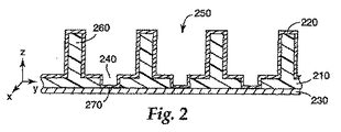
図2に、本発明の実施形態によるフローフィールドセパレータの断面図を示す。図2のフローフィールドセパレータは、例えば、燃料電池用途のユニポーラフローフィールドフィルムとして用いてよい。フローフィールドセパレータは、良好な寸法安定性と低熱膨張係数を有するポリマー等のポリマー材料で形成された可撓性基材層210を含む。例えば、ポリマーは、ポリメチルメタクリレート、ポリプロピレンおよびポリカーボネート等の材料から選択してよい。ポリカーボネートが好ましい。
FIG. 2 shows a cross-sectional view of a flow field separator according to an embodiment of the present invention. The flow field separator of FIG. 2 may be used, for example, as a unipolar flow field film for fuel cell applications. The flow field separator includes a
第1および第2の導電性層220、230は、基材210の反対表面に配置されている。ある実施形態において、接着層を、基材210と第2の層230との間に配置してもよい。例えば、接着層は、ゴム、シリコーンまたはアクリルベースの接着剤を含んでいてよい。エポキシ、イソシアネート等をはじめとするその他の接着層も考えられる。基材210は、1枚以上のフィルムを含み、導電性であっても、第1および第2の層より実質的に導電性が低くてもよい。第2の層230は可撓性で、アルミニウムホイル等の1枚以上の導電性フィルムおよび/またはホイルを含んでいてもよい。第1の層220は、ニッケル等の1種類以上の金属の導電性コーティングで形成されてもよい。ある実施形態において、接着促進層を、第1の層220と基材210との間に用いてもよい。例えば、接着促進層は、スパッタまたは蒸気コート金属層を含んでいてよい。接着促進層としては、サブモノレイヤーから数十または数百ナノメートルの厚さ範囲のニッケルまたはクロム/ニッケル金属層、金属フィルムの組み合わせを挙げることができる。
The first and second
セパレータは、第1の層220と第2の層230との間に電気的接触を提供する相互接続ゾーン270を含む。ゾーン270は、第1の導電性層220が、いくつかの小さめの不連続な領域および/または1つ以上の大きめの連続領域において、第2の導電性層230に電気的に接続されるように構成されている。ゾーン270は、セパレータのz軸を通る抵抗性電流を大幅に損失することなく、セパレータが大量の電流を通すように構成されている。第1の層220と第2の層230との間の相互接続ゾーン270は、約0.001オーム−cm2〜約0.1オーム−cm2の面積比抵抗を提供する。
The separator includes an
基材210は、少なくとも1つのチャネル250および1つのアパーチャ240を形成するフィーチャー260のフローフィールドパターンを含む。フローフィールドパターンは、基材210の表面に構造化フローフィールドパターンを画定する。チャネル250は、セパレータの表面を超えて燃料反応物質、副生成物および/または冷却剤の輸送を行う。フローフィールドの1つまたは複数のチャネル250は、基材210の表面を超えて蛇行パターン、曲線パターンおよび/または直線パターンをはじめとする様々なパターンを画定する。
The
基材表面260および/またはアパーチャ240は好ましくは成形により形成されるが、他のプロセスにより形成されてもよい。基材210のアパーチャ240は、第1の層220と第2の層230との間の相互接続ゾーン270の形成を促す。アパーチャ240は、基材の成形、ラミネーティング、レーザー切断、穿孔またはその他プロセスにより形成してよい。
The
第1の導電性層220は1種類以上の金属を含み、基材210の一表面のフィーチャー260をコンフォーマルにコートする。例えば、第1の層220は、基材フィーチャー260の表面にコンフォーマルな亜鉛めっき形成金属スキンを含んでよい。第1の層220の厚さは約3ミルで、好ましい厚さは約1.5〜2ミルであるが、厚さは約0.1ミル〜5ミルを超える厚さとすることができる。第1の層220の厚さは、基材210のフィーチャー260および/またはチャネル250に対して薄いのが好ましい。一般的なチャネル250の寸法は、約1ミル〜約100ミル、より好ましくは約3ミル〜約50ミル、より好ましくは約10ミル〜約35ミルである。通常、第1の層220は、チャネル250に比べて薄いままであり、第1の層220をできる限り薄く保つのが望ましい。
The first
第2の導電性層230は、第1の導電性層220から基材210の反対表面に配置されている。第2の層230は、ニッケル、アルミニウムまたはステンレス鋼といった金属ホイル等の可撓性の導電性材料を含む。第2の層230は、任意で、グラフオイル(GRAPHOIL)等のグラファイトの可撓性の形態またはその他導電性および可撓性材料で形成される。
The second
前述したとおり、基材210はアパーチャ240を含み、これを通して、電気的相互接続270が第1の層220と第2の層230との間に形成される。一実施形態において、アパーチャ240は、チャネルフィーチャー260を形成するのに用いる成形プロセスにより形成しても、別個のプロセス工程で形成してもよい。例えば、アパーチャ240は、後に第2の層230にラミネートされる複製基材フィルムを穿孔することにより形成してもよい。あるいは、アパーチャ240は、任意で、基材の第2の層230へのラミネーティングか成形後に形成してもよい。第1の層220は、基材210の表面にコンフォーマルに付着して、相互接続ゾーン270でアパーチャ240を通して第2の層との電気的接触を行う。
As previously described, the
基材210は、必ずしも、というわけではないが、導電性材料で形成されてもよい。基材が導電性の場合には、相互接続ゾーン270のみにより提供されるz軸導電性よりもセパレータのz軸導電性が促進される。上述した構造化基材210に近接する第1および第2の導電性層220、230はコンフォーマルな層であるため、流体チャネルは小さくすることができる。このフィーチャーは、燃料電池において非常に有用である。というのはフローフィールドを薄く製造でき、コンパクトなユニポーラまたはバイポーラフローフィールドフィルムおよび燃料電池設計をさらに促進することができるからである。
The
以下に詳述するとおり、靭性測定値を用いて、セパレータの突発的な破損に対する抵抗性を測定する。例えば、本発明の実施形態により形成されたセパレータは、本明細書に記載した靭性試験に従って測定したときに約20度を超える靭性試験値と、一方で、約4.5gm/cm3未満の平均嵩密度を維持する。 As described in detail below, the toughness measurement is used to measure resistance to sudden breakage of the separator. For example, separators formed according to embodiments of the present invention have a toughness test value of greater than about 20 degrees as measured according to the toughness test described herein, while an average of less than about 4.5 gm / cm 3. Maintain bulk density.
図3〜6は、本発明の実施形態による部分または完全形成されたセパレータの様々な顕微鏡写真である。図3は上述したセパレータの断面顕微鏡写真である。図3に、一連の相互接続ゾーンまたはビアを通して切断された断面を示す。基材のチャネルおよびアパーチャは、断面では不連続な段に見える。この例では、基材はポリマーで形成されており、第1の導電層はNi、第2の導電層(裏側層)はAlである。 3-6 are various photomicrographs of a partially or fully formed separator according to an embodiment of the present invention. FIG. 3 is a cross-sectional photomicrograph of the separator described above. FIG. 3 shows a cross section cut through a series of interconnect zones or vias. The substrate channels and apertures appear to be discontinuous steps in cross section. In this example, the base material is formed of a polymer, the first conductive layer is Ni, and the second conductive layer (back side layer) is Al.
図4および5に、図2および3に示す以外の異なる断面形状を有する成形基材を示す。基材の成形表面は湾曲して、チャネルおよびアパーチャを形成する。図4に、アルミニウムベース層に配置されたポリマー基材のいくつかのチャネル/アパーチャフィーチャーの断面図を示す。図5は、基材とアルミニウムベース層との間の界面の拡大図である。図6は、基材に形成されたアパーチャを含む基材チャネルの平面の顕微鏡写真である。 FIGS. 4 and 5 show molded substrates having different cross-sectional shapes other than those shown in FIGS. The molding surface of the substrate is curved to form channels and apertures. FIG. 4 shows a cross-sectional view of several channel / aperture features of a polymer substrate disposed on an aluminum base layer. FIG. 5 is an enlarged view of the interface between the substrate and the aluminum base layer. FIG. 6 is a planar photomicrograph of a substrate channel that includes an aperture formed in the substrate.
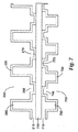
図7に示す一実施形態において、セパレータの熱除去特性をさらに促進するために、熱移動流体を含有するように構成された一組のチャネル750をセパレータは含む。図7に示すとおり、本実施形態は、第1の基材210により画定されるチャネル250の反対の第2の組のチャネル750を画定する第2の基材710を含む。第1のチャネル250は、第2の組のチャネル750と整合する必要はない。同じく、電気的接続270および770も整合する必要はない。同じく、アパーチャ240および740も整合する必要はない。本発明のセパレータの薄さはまた、電気的接続270および770と組み合わせて、第1の層220側から第3の層側720まで熱の移動を補助する。
In one embodiment, shown in FIG. 7, the separator includes a set of
図7に示すとおり、第2の基材710は第2の層230に配置される。第1および第2の基材210、710の表面に形成されたフィーチャー260、760のパターンは、図2に関して説明したとおり、チャネル250、750を形成する。第1の基材210は、導電性の第1の層220でコンフォーマルにコートされる。第2の基材710を、導電性の第3の層720でコンフォーマルにコートしてもよい。第1の基材のアパーチャ240によって、第1の層220と第2の層230との間の電気的相互接続ゾーン270が得られる。操作中、熱導電性流体は、第2の基材710のチャネル750を流れて、熱エネルギーがセパレータから離れて流れる。熱エネルギーは、第1の層220と第2の層230との間のz軸相互接続270点で高流動速度を有する。
As shown in FIG. 7, the
本発明の実施形態は、図8に示すバイポーラフローフィールドセパレータに関する。バイポーラフローフィールドセパレータは、第2の層230に配置された反対の可撓性基材層210、910を含む。第1および第2の基材210、910は、チャネル250、950およびアパーチャ240、940を形成するフィーチャー260、960を含む。第1の導電性層220を、第1の基材210の表面に形成して、第1の層220が第1の基材210のフィーチャー260に沿うようにする。第1の基材210のアパーチャによって、第1の層220を第2の層230に電気的に接続する電気的相互接続ゾーン270が形成される。
The embodiment of the present invention relates to the bipolar flow field separator shown in FIG. The bipolar flow field separator includes opposite
第3の導電性層920を、第2の基材910の表面に形成して、第3の層920が第2の基材910のフィーチャー960に沿うようにする。第2の基材910のアパーチャ940によって、第3の層920を第2の層230に電気的に接続する電気的相互接続ゾーン970が形成される。この構成では、セパレータの両表面を反応物質および/または副生成物のフローフィールドとして用いてよい。セパレータをバイポーラフローフィールドフィルムとして利用して、フィルムを流れるz軸電流を提供する。あるいは、冷却チャネルを一表面に、反応物質チャネルを反対表面に有し、z軸電流がフィルムを流れるユニポーラフローフィールドフィルムとしてセパレータをこの構成で用いてもよい。
A third
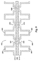
図9に示す本発明の実施形態は、バイポーラフィルムから離れて熱を伝導するのに用いる内部チャネル1090を有するバイポーラフローフィールドセパレータに関する。本実施形態によれば、3つの別個の流体移動領域が提供される。内部冷却チャネル1090は、セパレータ内の冷却剤フローを促す。反応物質および/または副生成物は、バイポーラセパレータの2つの外側表面でチャネル250、950を流れる。
The embodiment of the present invention shown in FIG. 9 relates to a bipolar flow field separator having an
本実施形態によれば、セパレータの第2の層230は、冷却剤流体のフローを促すチャネル1090を含む。本実施形態において、第2の層230は、押出しアルミニウムホイル等の押出しホイル構造を含む。第1および第2の基材210、910は、第2の層230の反対表面に形成されている。第1および第2の基材210、910は、チャネル250、950およびアパーチャ240、940を形成するフィーチャー260、960を含む。第1の導電性層220を、第1の基材210の表面に形成して、第1の層220が第1の基材210のフィーチャー260に沿うようにする。第1の基材210のアパーチャ240によって、第1の層220を第2の層230に電気的に接続する電気的相互接続ゾーン270が形成される。
According to this embodiment, the second layer of
第3の導電性層920を、第2の基材910の表面に形成して、第3の層920が第1の基材910のフィーチャー960に沿うようにする。第2の基材910のアパーチャによって、第3の層920を第2の層230に電気的に接続する電気的相互接続ゾーン970が形成される。
A third
いくつかの実施形態には、セパレータの表面に任意のコーティングが含まれていてよい。一実施形態によれば、任意の耐食性コーティングを上述の第1、第2および/または第3の層の1つ以上に付着してもよい。例えば、耐食性層を用いて、金属の腐食を防ぎ、第1、第2および/または第3の層間で約0.001オーム−cm2〜約0.1オーム−cm2等の適切な面積比抵抗を維持する。 Some embodiments may include an optional coating on the surface of the separator. According to one embodiment, an optional corrosion resistant coating may be applied to one or more of the first, second and / or third layers described above. For example, a corrosion resistant layer may be used to prevent metal corrosion and a suitable area ratio such as about 0.001 ohm-cm 2 to about 0.1 ohm-cm 2 between the first, second and / or third layers. Maintain resistance.
他の実施形態によれば、コーティングを第1、第2のおよび/または第3の層の表面に適用して、接触抵抗を減じてもよい。かかるコーティングを用いると、セパレータの全体的な電気抵抗が減じる。 According to other embodiments, a coating may be applied to the surface of the first, second and / or third layer to reduce contact resistance. With such a coating, the overall electrical resistance of the separator is reduced.
本発明の他の実施形態によれば、接着コーティングを基材と第2の層との間に適用してもよい。 According to other embodiments of the invention, an adhesive coating may be applied between the substrate and the second layer.
基材は、エラストマー特性を有する材料で形成してもよい。エラストマー基材だと、ガスケットが提供されるようにセパレータを構成することができる。セパレータの特定の領域に流体を含ませる必要がある用途に本実施形態は特に有用である。例えば、燃料電池用途においては、セパレータは、ユニポーラまたはバイポーラフローフィールドセパレータと、燃料電池スタックの近接構造の周囲領域間でガスケットとして機能するエラストマー基材を含む。エラストマー基材により形成されるガスケット領域を用いて、例えば、燃料電池アセンブリに一般的に用いられる別個のシールに交換してもよい。 The substrate may be formed of a material having elastomeric properties. With an elastomeric substrate, the separator can be configured to provide a gasket. This embodiment is particularly useful for applications that require fluid to be included in specific areas of the separator. For example, in fuel cell applications, the separator includes a unipolar or bipolar flow field separator and an elastomeric substrate that functions as a gasket between the peripheral regions of the adjacent structure of the fuel cell stack. The gasket area formed by the elastomeric substrate may be used to replace a separate seal commonly used for fuel cell assemblies, for example.
図10および11に、本発明の実施形態によるユニポーラ燃料電池フローフィールドフィルムとして用いるのに好適なフローフィールドセパレータの第1の表面1100および第2の表面1200を示す。図11および12に示すとおり、セパレータの第1の表面1100は、反応物質チャネルの蛇行パターンを有するフローフィールド1111を含む。セパレータの第2の表面1200は、冷却チャネルを有する冷却領域1211を組み込んでいる。本用途では、図11および12に示す構成の2つのセパレータが、燃料電池ユニット化電池アセンブリ(UCA)を形成するために、ポリマー電解質膜(PEM)層、拡散器/集電装置(DCC)層、フローフィールドセパレータフィルム間に挟まれたアノードおよびカソード触媒層で構成されている。
10 and 11 show a first surface 1100 and a
図11および12のセパレータは、冷却剤入口マニホルド1221、1222、冷却剤出口マニホルド1223、1224を囲む領域、燃料入口マニホルド1131〜1133、燃料出口マニホルド1134、1135を囲む領域、および/または接続ロッドホール1241を囲む周囲領域等のUCA構造の様々な領域のシーリングを促す表面を含む。
The separators of FIGS. 11 and 12 include
前述したとおり、セパレータ基材は、冷却剤および燃料マニホルド1131〜1135、1221〜1224を囲む領域ならびに接続ロッドホール1241を囲む周囲領域にガスケットを提供するエラストマー材料で形成される。燃料電池操作のガスケットによって、燃料電池操作を大幅に劣化させる恐れのある冷却剤および/または燃料電池漏れの可能性が減じる。
As described above, the separator substrate is formed of an elastomeric material that provides a gasket in the region surrounding the coolant and fuel manifolds 1131-1135, 1221-1224, and in the peripheral region surrounding the connecting
図12に、接続ロッドホール1241を通したセパレータの断面を示す。セパレータは、チャネル1150、1250を形成するフィーチャー1160、1260を有する第1の基材1110および第2の基材1210と第1および第2の基材1110、1210にアパーチャ1140、1240を含む。第1の基材1110の一部は、コンフォーマルな金属層である第1の層1120と第2の層1130との間に配置される。第1の層1120は、第1の基材1110のアパーチャ1140により提供される相互接続ゾーン1170で第2の層1130と接触する。第2の基材1210の一部は、第2の層1130と第3のコンフォーマルな層1220との間に配置される。第3の層1220は、第2の基材1210のアパーチャ1240により提供される相互接続ゾーン1270で第2の層1130と接触する。
FIG. 12 shows a cross section of the separator through the connecting
第1の表面1100のチャネル1150は、燃料電池の反応物質燃料にフローフィールドを提供する。液体冷却剤を第2の表面1200のチャネル1250を通して分散して、燃料電池の活性領域からの熱を除去してよい。セパレータは、第1および第3の層を電気的に接続する相互接続ゾーン1170、1270を介してz軸で集電する。
The
図13は、表面1200から示した図11および12のセパレータについての相互接続ゾーン1170、1270の可能な構成の詳細図である。相互接続ゾーン1170、1270は、導電性の第1および第3のコンフォーマルな層が同じく導電性である第2の層と接触する複数の領域を含む。かかる構成は、集電のための低抵抗接続を提供する。
FIG. 13 is a detailed view of a possible configuration of
図10〜12に示したとおり、セパレータはまた、フローフィールド1111、1121を超えて、冷却剤および燃料マニホルド1131〜1135、1221〜1224を周囲領域ならびに接続ロッドホール1241を包含する領域まで延在していてもよい。本発明の実施形態によれば、第1および第2の基材1110、1210は、これらの周囲領域の1つ以上についてのガスケットを促進するエラストマー材料で形成してもよい。周囲領域の基板1110、1210は、圧縮性ガスケットを形成するフローフィールド領域より厚くしてもよい。図12に示すとおり、基材1110、1210は、周囲領域1175に第1および第3のコンフォーマル層を含む必要はない。
As shown in FIGS. 10-12, the separator also extends beyond the
図14に、本発明の実施形態による燃料電池用途のユニット化電池アセンブリ(UCA)1550を示す。UCA1550は、1つ以上のユニポーラフローフィールドフィルム1552、1556、1554を用いることにより、多数のMEA1525aおよび1525bを組み込んでいる。図14に示す構成において、UCA1550は2つのMEA1525aおよび1525bと、4つのユニポーラフローフィールドフィルム1552、1554、1556を組み込んでいる。ユニポーラフローフィールドフィルム1556は、一表面1556bに冷却チャネルを組み込んでいる。あるいは、2つのユニポーラフローフィールドフィルム1556を、ここで述べたように、内部冷却チャネルを有するバイポーラフローフィールドフィルムに交換してもよい。UCAは、米国特許出願第11/025267号(弁護士整理番号60138US002)に記載されているような好適な方法または機構により一緒に保持してもよい。
FIG. 14 illustrates a unitized cell assembly (UCA) 1550 for fuel cell applications according to an embodiment of the present invention.
MEA1525aは、拡散器/集電装置(DCC)1566aと1564aとの間に挟まれたカソード1562a/膜1561a/アノード1560a層状構造を含む。DCC1564aは、ユニポーラフローフィールドフィルム1556の第1のフローフィールド表面1556aに近接配置されている。ユニポーラフローフィールドフィルム1556の第2のフローフィールド表面1556bは冷却チャネルを含む。DCC1566aは、フローフィールドフィルム1552に近接配置されていて、ユニポーラフローフィールドフィルムまたはバイポーラフィルムとして構成してよい。フローフィールドフィルム1552が、ユニポーラフローフィールドフィルムとして構成されている場合には、一表面1552aが反応物質フローフィールドを含み、第2の表面1552bが冷却剤フローフィールドを含んでいてよい。
The
MEA1525bは、拡散器/集電装置(DCC)1566bと1564bとの間に挟まれたカソード1562b/膜1561b/アノード1560b層状構造を含む。DCC1564bは、ユニポーラフローフィールドフィルム1556の第1のフローフィールド表面1556aに近接配置されている。ユニポーラフローフィールドフィルム1556の第2のフローフィールド表面1556bは冷却チャネルを含む。DCC1566bは、フローフィールドフィルム1554に近接配置されていて、ユニポーラフローフィールドフィルムまたはバイポーラフィルムとして構成してよい。フローフィールドフィルム1554が、ユニポーラフローフィールドフィルムとして構成されている場合には、一表面1554aが反応物質フローフィールドを含み、第2の表面1554bが冷却剤フローフィールドを含んでいてよい。
The MEA 1525b includes a
図14に示す構造の多数のUCAをポリマー溶着により結合して、燃料電池スタックを形成する。その他の好適な結合手段としては、クリップ、スクリュー、接着剤、エポキシ、スナップロックやデュアルロック(DUAL−LOCK)(登録商標)により実証されている機械的締め代、ロッキングテーパー等が挙げられる。 A number of UCAs having the structure shown in FIG. 14 are joined by polymer welding to form a fuel cell stack. Other suitable coupling means include clips, screws, adhesives, epoxies, mechanical locks as demonstrated by Snap Lock or Dual-LOCK®, locking taper, and the like.
燃料電池スタックは、UCAおよび/またはUCAコンポーネント間のシーリングを促進するために整合された多数のUCAを圧縮することにより形成される。例えば、燃料電池スタックは、UCAの周囲部分を通過して、スタックに所定の圧力を適用する接続ロッドを用いて整合および圧縮される。UCAの1つ以上のコンポーネントは、圧縮プロセス中にUCAを整合する役割を果たす位置合せフィーチャーを含んでいてよい。本明細書で述べたとおり、セパレータは、UCAにガスケットを提供する。図1bに示すとおり、別個のガスケットを用いてスタックのシーリングを促進してもよい。 A fuel cell stack is formed by compressing multiple UCAs aligned to facilitate sealing between UCAs and / or UCA components. For example, the fuel cell stack is aligned and compressed using connecting rods that pass through the peripheral portion of the UCA and apply a predetermined pressure to the stack. One or more components of the UCA may include alignment features that serve to align the UCA during the compression process. As described herein, the separator provides a gasket to the UCA. As shown in FIG. 1b, a separate gasket may be used to facilitate stack sealing.
本発明の一実施形態には、燃料電池スタックでUCAを交換する方法が包含される。一例において、UCAが欠陥があると判断された場合には、燃料電池スタックのUCAの交換が望ましい。例えば、1つ以上の不良MEAを含む場合には、UCAは欠陥がある。この場合、接続ロッドのナットと緩める等して、燃料電池スタックのUCAから圧縮を取り除く。欠陥のあるUCAを取り外して、交換するUCAをスタックに挿入する。燃料電池スタックに圧縮を再度適用する。 One embodiment of the present invention includes a method for replacing a UCA in a fuel cell stack. In one example, if it is determined that the UCA is defective, it is desirable to replace the UCA of the fuel cell stack. For example, a UCA is defective if it contains one or more defective MEAs. In this case, the compression is removed from the UCA of the fuel cell stack, such as by loosening the nut of the connecting rod. Remove the defective UCA and insert the replacement UCA into the stack. Re-apply compression to the fuel cell stack.
圧縮プロセス中、UCAコンポーネントを適正な整合で維持する。適正な整合は、例えば、UCAの1つ以上のコンポーネントの位置合せフィーチャーにより維持される。燃料電池スタックの圧縮には、接続ロッドナットを所定のシーケンスで所定の圧力まで締結して、燃料電池表面の均一な圧縮が促進されるようにすることが包含される。 Maintain UCA components in proper alignment during the compression process. Proper alignment is maintained, for example, by alignment features of one or more components of the UCA. Compression of the fuel cell stack includes tightening the connecting rod nuts to a predetermined pressure in a predetermined sequence to facilitate uniform compression of the fuel cell surface.
一実施形態によれば、可撓性フローフィールドセパレータを製造する方法には、ポリマー基材層の第2の表面を、アルミニウムホイル等の可撓性の導電性材料の第2の層と接触させて配置することが包含される。第2の層および/または基材は1枚以上のフィルムを含んでいてよい。ある実施形態において、基材はポリプロピレンまたはポリカーボネート等のポリマーフィルムで形成し、第2の層はアルミニウムホイルまたはフィルムで形成してよい。構造化フローフィールドパターンは、基材の第1の表面で形成される。基材の第1の表面は、導電性材料の第1の層、例えば、ニッケルでコートされる。第1の層は、1つ以上の位置で第2の層と接触して、第1の層と第2の層との間に導電性を確立している。 According to one embodiment, a method of manufacturing a flexible flow field separator includes contacting a second surface of a polymer substrate layer with a second layer of flexible conductive material such as aluminum foil. Is included. The second layer and / or substrate may include one or more films. In certain embodiments, the substrate may be formed of a polymer film such as polypropylene or polycarbonate and the second layer may be formed of an aluminum foil or film. A structured flow field pattern is formed on the first surface of the substrate. The first surface of the substrate is coated with a first layer of conductive material, for example nickel. The first layer is in contact with the second layer at one or more locations to establish electrical conductivity between the first layer and the second layer.
フローフィールドパターンの形成は、基材層に成形プロセスを行って、構造化フィーチャー、例えば、チャネルとアパーチャを基材の表面に形成することによりなされる。代表的な方法としては、圧縮成形、射出成形、押出しエンボス加工、押出しコーティングおよび鋳造と硬化が挙げられる。基材層を形成するのに用いる材料は、熱可塑性ポリマー、ポリマーコンポジットまたは硬化性ポリマー樹脂処方とすることができる。代表的な構造フィーチャーとしては、V形リブ、上部が平坦なリブおよびポストや不連続リブが挙げられる。構造の設計は、燃料電池の必要性に応じて異なる。代表的な深さは約1ミル〜100ミル、より好ましくは約3ミル〜50ミルである。リブは、鋭い先端を有するか、または丸めた先端、さらには平坦な先端を有する。 The flow field pattern is formed by performing a molding process on the substrate layer to form structured features such as channels and apertures on the surface of the substrate. Typical methods include compression molding, injection molding, extrusion embossing, extrusion coating and casting and curing. The material used to form the substrate layer can be a thermoplastic polymer, a polymer composite or a curable polymer resin formulation. Typical structural features include V-shaped ribs, flat top ribs, posts and discontinuous ribs. The design of the structure varies depending on the needs of the fuel cell. A typical depth is about 1 mil to 100 mils, more preferably about 3 mils to 50 mils. The ribs have a sharp tip or a rounded tip, and even a flat tip.
ある実施形態において、基材を成形またはラミネートして、パターンを形成し、第1の層をパターン上に付着する。他の実施形態において、第1の層を平滑な基材に付着し、層状構造を圧縮成形でエンボス加工して、パターンを形成する。基材の成形またはラミネートは、基材を第2の層に配置する前後に行ってよい。 In certain embodiments, the substrate is molded or laminated to form a pattern and a first layer is deposited on the pattern. In other embodiments, the first layer is attached to a smooth substrate and the layered structure is embossed by compression molding to form a pattern. The molding or laminating of the substrate may be performed before or after placing the substrate on the second layer.
セパレータは、フローフィールドがセパレータの片面または両面にあるように製造してもよい。一実施形態において、セパレータの第1の表面のフローフィールドは、反応物質および/または副生成物の輸送に用い、セパレータの第2の表面のフローフィールドは液体またはガス状冷却剤のために用いてよい。セパレータの一表面に反応物質フローフィールドおよび反対の表面に冷却剤フローフィールドを利用するセパレータを、一体冷却型の燃料電池ユニポーラフローフィールドフィルムとして実施してもよい。 The separator may be manufactured such that the flow field is on one or both sides of the separator. In one embodiment, the flow field on the first surface of the separator is used for transport of reactants and / or byproducts, and the flow field on the second surface of the separator is used for liquid or gaseous coolant. Good. A separator that utilizes a reactant flow field on one surface of the separator and a coolant flow field on the opposite surface may be implemented as an integrally cooled fuel cell unipolar flow field film.
他の実施形態において、セパレータの両側にあるフローフィールドは、バイポーラフローフィールドセパレータとして利用してもよい。 In other embodiments, the flow field on either side of the separator may be utilized as a bipolar flow field separator.
両表面に反応物質フローフィールドを有するバイポーラフローフィールドセパレータおよび一表面に反応物質フローフィールドそして他表面に冷却剤チャネルを備えたユニポーラフローフィールドセパレータは同様の方法を用いて形成してよい。本発明の実施形態に従ってかかる構造を形成する方法は、第1および第2のポリマー基材を第2の層の第1および第2の表面に配置することを包含する。構造化フローフィールドパターンを、第1の基材の表面および第2の基材の表面に形成する。第1の層を第1の基材の表面に付着する。第3の層を第2の基材の表面に付着する。 A bipolar flow field separator having a reactant flow field on both surfaces and a unipolar flow field separator with a reactant flow field on one surface and a coolant channel on the other surface may be formed using similar methods. A method of forming such a structure according to an embodiment of the present invention includes disposing first and second polymer substrates on the first and second surfaces of the second layer. A structured flow field pattern is formed on the surface of the first substrate and the surface of the second substrate. The first layer is attached to the surface of the first substrate. A third layer is attached to the surface of the second substrate.
様々な実施形態によれば、第1の層と第2の層との間および/または第3の層と第2の層との間に、第1の層と第2の層との間に1つ以上の不連続な導電性パスまたはゾーンを介して電気的な相互接続を確立してよい。例えば、第1および第2の基材のうち一方または両方にアパーチャを形成し、第1の層と第2の層との間および/または第3の層と第2の層との間に、1つ以上の基材アパーチャを通して電気的な相互接続を確立する。アパーチャは、上述したラミネーティングまたは成形プロセスの一部として形成したり、レーザー処理、穿孔または機械的ツールによる切断により形成してもよい。 According to various embodiments, between the first layer and the second layer and / or between the third layer and the second layer, between the first layer and the second layer. Electrical interconnection may be established through one or more discrete conductive paths or zones. For example, forming an aperture in one or both of the first and second substrates, and between the first layer and the second layer and / or between the third layer and the second layer, Establish electrical interconnection through one or more substrate apertures. The aperture may be formed as part of the laminating or molding process described above, or may be formed by laser treatment, drilling or cutting with a mechanical tool.
第1の層は1種類以上の金属を含み、パターン形成前後に基材に付着させてもよい。第1の層は、例えば、電気めっき、蒸着、スパッタリングまたはその他コーティング技術をはじめとする様々なプロセスにより基材の第1の表面に付着することができる。 The first layer may include one or more metals and may be attached to the substrate before and after pattern formation. The first layer can be applied to the first surface of the substrate by various processes including, for example, electroplating, vapor deposition, sputtering or other coating techniques.
ある実施形態において、第1の層は多層構造を含んでよい。第1の層は、ある付着プロセスにより第1の副層を基材に付着し、異なる付着プロセスにより第1の副層に第2の副層を付着することにより形成されてもよい。第1および第2の副層は同じ金属を含み、第1の副層は第2の副層とは異なる金属を含んでよい。 In certain embodiments, the first layer may include a multilayer structure. The first layer may be formed by depositing the first sublayer to the substrate by one deposition process and depositing the second sublayer to the first sublayer by a different deposition process. The first and second sublayers may include the same metal, and the first sublayer may include a different metal than the second sublayer.
一例において、第1の副層は基材へのニッケルの蒸着により形成されてよい。第2の副層は第1の副層のニッケルの電気めっきにより形成されてよい。この例では、第1の副層は比較的薄い層を含み、第2の副層は第1の層のバルクを形成している。他の例において、第1の副層は基材への銅の蒸着により形成され、第2の副層は銅の副層へのニッケルの蒸着により形成される。 In one example, the first sublayer may be formed by vapor deposition of nickel on the substrate. The second sublayer may be formed by electroplating nickel of the first sublayer. In this example, the first sublayer includes a relatively thin layer and the second sublayer forms the bulk of the first layer. In another example, the first sublayer is formed by copper deposition on a substrate and the second sublayer is formed by nickel deposition on a copper sublayer.
さらなる層を第1の層および/または第2の層に配置してもよい。一例において、追加の層は熱伝導性層を含んでよい。他の例において、追加の層はベース層の抵抗性を減じる層を含んでよい。さらに他の例において、追加の層は耐食性層を含む。 Additional layers may be disposed on the first layer and / or the second layer. In one example, the additional layer may include a thermally conductive layer. In other examples, the additional layers may include layers that reduce the resistance of the base layer. In yet other examples, the additional layer includes a corrosion resistant layer.
第2の層はアルミニウムやその他金属等の金属ホイルであってよい。場合によっては、第2の層を押出して、複数の内部チャネルを金属ホイル内に形成してもよい。内部チャネルは、チャネルを流れる冷却剤フローのために用いてよい。各表面に内部チャネルおよびフローフィールドを有するセパレータは、表面を超えた、かつ/またはセパレータ内での3種類の流体の動きのための領域を提供する。セパレータは、反応物質、副生成物、冷却剤および/またはその他物質の、表面のフローフィールドおよびセパレータ内部への行き来をさせるための入口と出口ポートを含んでいてよい。 The second layer may be a metal foil such as aluminum or other metals. In some cases, the second layer may be extruded to form a plurality of internal channels in the metal foil. The internal channel may be used for coolant flow through the channel. A separator with internal channels and flow fields on each surface provides a region for movement of the three types of fluids across the surface and / or within the separator. The separator may include inlet and outlet ports for directing reactants, by-products, coolants and / or other materials to and from the surface flow field and the interior of the separator.
本明細書に記載したセパレータは可撓性で、連続処理技術を用いて形成してよい。本明細書に記載した可撓性セパレータは、不連続なコンポーネントまたは連続ロールで複数のコンポーネントとして形成してもよい。 The separators described herein are flexible and may be formed using continuous processing techniques. The flexible separator described herein may be formed as a plurality of components with discontinuous components or continuous rolls.
これらの実施例において、チャネルはポリプロピレンから形成され、平らな裏側金属層はアルミニウムで構成され、前側コンフォーマル層はニッケルでできている。試料は、アルミニウムホイルおよびポリプロピレンにツールをエンボス加工し、チャネルベースで露出したアルミニウムでチャネルを形成することにより形成した。ホイルをNi蒸気コートし、亜鉛めっき形成Niの他層をNi蒸気コートに付着した。通電容量、抵抗および燃料電池性能について試料を試験した。 In these embodiments, the channels are made of polypropylene, the flat back metal layer is made of aluminum, and the front conformal layer is made of nickel. Samples were formed by embossing the tool in aluminum foil and polypropylene and forming the channel with aluminum exposed at the channel base. The foil was Ni vapor coated and another layer of galvanized Ni was deposited on the Ni vapor coat. Samples were tested for current carrying capacity, resistance and fuel cell performance.
実施例1
ノースカロライナ州のウィンストン−セーラムのRJRパッケージング(RJR Packaging、Winston−Salem,NC)製の3ミルのポリプロピレンコートされたアルミニウムホイル(RJRホイル、KW384−116、ID003)を本実施例のセパレータ用導電性材料ベースとして用いた。次に、シェルケミカルカンパニー(Shell Chemical Company)(テキサス州、ヒューストン(Houston Texas))製の厚さ8ミルの2層の超高衝撃エチレン/プロピレンコポリマーSRD7−560(30MFI)をポリコートAlホイルに配置して、後述するV溝ツールを用いてウォバッシュバンテージプレス(Wabash Vantage press)、型番V75H−24−CLXにパターン1としてプレスした。プレス条件は次の通りであった。
Example 1
Conductivity for the separator of this example is 3 mil polypropylene coated aluminum foil (RJR foil, KW384-116, ID003) from RJR Packaging, Winston-Salem, NC, Winston-Salem, NC Used as material base. Next, two 8 mil thick ultra-high impact ethylene / propylene copolymer SRD7-560 (30 MFI) from Shell Chemical Company (Houston Texas, Tex.) Is placed on the polycoated Al foil. Then, it was pressed as a pattern 1 on a Wabash Vantage press, model number V75H-24-CLX, using a V groove tool described later. The press conditions were as follows.
ステップ1:ツール、ポリプロピレン層、Alホイルおよびクロムめっきプレスプレートを175℃に予熱しておいたプレスに入れる。内側プラテン制御を175℃にセットし、外側プラテンを150℃にセットした。プレスを閉じ、20psiでクランプした。この状態を5分間保持した。 Step 1: Place the tool, polypropylene layer, Al foil and chrome plated press plate into a press preheated to 175 ° C. The inner platen control was set at 175 ° C and the outer platen was set at 150 ° C. The press was closed and clamped at 20 psi. This state was maintained for 5 minutes.
ステップ2:温度を175℃に維持し、圧力を200psiまで上げた。この状態を10分間保持した。 Step 2: The temperature was maintained at 175 ° C. and the pressure was increased to 200 psi. This state was maintained for 10 minutes.
ステップ3:圧力を200psiのままとし、水冷をオンにした。プラテン熱電対が40℃〜50℃の温度を示したらプレスを開けた。 Step 3: The pressure remained at 200 psi and water cooling was turned on. The press was opened when the platen thermocouple showed a temperature between 40 ° C and 50 ° C.
ステップ4:試料をプレスから取り出し、ツールから剥ぎ取った。ステップ4の後のように見えるアルミニウムおよびポリプロピレン界面の例を図4および5の顕微鏡写真に示す。 Step 4: The sample was removed from the press and peeled off from the tool. An example of an aluminum and polypropylene interface that looks like after step 4 is shown in the micrographs of FIGS.
次の工程で、導電層をポリプロピレンに与え、微細構造側をAlホイルに接続した。フィルムをNiで蒸気コートして、酸素グロー放電ステップの後、Ni蒸気コーティングをした。導電性Ni層を付着する複数ステッププロセスは、拡散ポンプDVB44デントンボックスコーター(Denton box coater)(ニュージャージー州、チェリーヒル、デントンバキューム(Denton Vacuum,Cherry Hill,NJ))を用いた。まず、真空チャンバを2.0×10⁻⁶トルまで引いた。次に、高真空バルブを閉じ、バイパスバルブを開き、20sccmの酸素の供給を開始した。バイパスバルブを締めて4mトルのチャンバ圧力とした。ウェブを10分間予熱して、400ミリアンペアにセットした酸素プラズマ源を用いて良好なNi接着を得た。酸素バルブおよびバイパスバルブを閉じ、高真空バルブを開いて、2.0×10⁻⁶トルのチャンバ圧力とした。750オングストロームのNi層を、1秒当たり3オングストロームで電子ビーム蒸着プロセスで付着した。このプロセスをウェブの反対側で繰り返した。最後に、フィルムをNiめっき漕に入れ、NiをNi/hr0.001”の速度でフィルム表面に付着した。600オングストロームの層はコンフォーマルで性質が均一であり、チャネルベースで露出したAlホイルと電気的に接触させた。ステップ4:試料をプレスから取り出し、ツールから剥ぎ取った。ステップ4の後のように見えるアルミニウムおよびポリプロピレン界面の例を図4および5の顕微鏡写真に示す。 In the next step, the conductive layer was applied to polypropylene and the microstructure side was connected to Al foil. The film was vapor coated with Ni and after the oxygen glow discharge step, Ni vapor coated. The multi-step process of depositing the conductive Ni layer used a diffusion pump DVB44 Denton box coater (Denton Vacuum, Cherry Hill, NJ). First, the vacuum chamber was pulled to 2.0 × 10 −6 Torr. Next, the high vacuum valve was closed, the bypass valve was opened, and the supply of 20 sccm of oxygen was started. The bypass valve was tightened to a chamber pressure of 4 mTorr. The web was preheated for 10 minutes and good Ni adhesion was obtained using an oxygen plasma source set at 400 milliamps. The oxygen valve and bypass valve were closed and the high vacuum valve was opened to a chamber pressure of 2.0 × 10 −6 Torr. A 750 Å Ni layer was deposited by an electron beam evaporation process at 3 Å per second. This process was repeated on the other side of the web. Finally, the film was placed in a Ni plating trough and Ni was deposited on the film surface at a rate of Ni / hr 0.001 ". The 600 Å layer was conformal and uniform in nature, with channel-exposed Al foil and Step 4: The sample was removed from the press and peeled off from the tool An example of an aluminum and polypropylene interface that appears after step 4 is shown in the photomicrographs of FIGS.
実施例2
本実施例において、チャネルおよび電気的接触ゾーン用に用いるNiツーリングを、パターン2として後述する矩形チャネルでツールを用いて形成した以外は実施例1と条件は同一であった。基材に不連続な穴が形成され、そこでは前面から後面に電流が流れた。図6に、このツールにより基材に切断されたアパーチャを示す。
Example 2
In this example, the conditions were the same as in Example 1 except that the Ni tooling used for the channel and the electrical contact zone was formed as a pattern 2 using a tool in a rectangular channel described later. Discontinuous holes were formed in the substrate, where current flowed from the front to the back. FIG. 6 shows the aperture cut into the substrate by this tool.
実施例3
実施例3については、用いたAlホイルが4ミルの超軟質(dead soft)アルミニウムホイルで、片側のみにポリマーコーティングを有し、Alホイルの裏側(非構造化側)を未コートのままとした以外は、条件およびツーリングは実施例1と同一であった。ホイルは、ヒュックフォリエン株式会社(HUECK FOLIEN GmbH&Co.KG)ピルクミュール(Pirkmuehle)14−16 D−92712ピルク(Pirk)、ロット番号1020007の冷間成形PPフィルムパック(firmpak)であった。
Example 3
For Example 3, the Al foil used was a 4 mil dead soft aluminum foil with a polymer coating on one side only, leaving the back side of the Al foil (unstructured side) uncoated. Except for the above, the conditions and tooling were the same as in Example 1. The foil was a cold-formed PP film pack of HUECK FOLIEN GmbH & Co. KG, Pilkmuehle 14-16 D-92712 Pilk, lot number 1020007.
ツーリング説明:
ツールパターン1:90°先端、20°ノッチ、41.24ミルピッチおよび30ミルチャネル深さのV溝パターン。90°先端は0.8ミルの半径を有していた。V溝壁は曲がって、20°底角および90°先端角にフィットした。
Touring instructions:
Tool pattern 1: V groove pattern with 90 ° tip, 20 ° notch, 41.24 mil pitch and 30 mil channel depth. The 90 ° tip had a radius of 0.8 mil. The V-groove wall was bent to fit a 20 ° base angle and a 90 ° tip angle.
ツールパターン2:20ミルの高さのチャネルの矩形チャネルパターン。チャネルの上幅は20ミル、底幅は25.62ミルである。チャネルは30.62ミルのピッチである。チャネル壁は直線である。チャネルの上部は矩形ポストである。ポストは9ミルの高さ、6.8ミルの幅および41ミルの長さである(チャネル方向に)。ポストはチャネル方向に0.35インチ(0.89cm)のピッチ、交差チャネル方向に30.62ミルピッチ(各チャネルはポストを有する)である。ポストは、交差チャネル方向に互いに整合されている。
Tool pattern 2: A rectangular channel pattern of
靭性試験を行って、本発明の実施形態により形成されたセパレータの靭性を、コンポジットグラファイトプレートと比較した。靭性試験は、材料の突発的な破損に対する抵抗性を測定するものである。本発明の実施形態に従って形成されたアルミニウム/ポリプロピレン/ニッケル層状セパレータの3つの試料の靭性を後述するプロセスを用いて試験した。セパレータは、アルミニウムの第1の層、ポリプロピレン基材およびニッケルの第1の層を含んでおり、全体の厚さは約0.144cmであった。靭性試験に用いたアルミニウム/ポリプロピレン/ニッケル層状セパレータ試料の平均嵩密度は約3gm/cm3であった。靭性試験に用いるアルミニウム/ポリプロピレン/ニッケル層状セパレータを図7に示す。第1および第2の基材は別々に形成してから第2の層にラミネートした。第1および第2の基材をまず、ステンレス鋼ツールに対するポリプロピレンコポリマー7C50(ミシガン州ミッドランドのダウケミカル(Dow Chemical,Midland,MI))の圧縮成形により製造して、チャネル壁を形成した。第1の基材は84ミルのピッチで深さ30ミルのチャネルを有していた。第1の基材チャネルは、横断幅が7.1cmで、チャネル領域に11.1cmの幅を13横断する蛇行チャネルであった。チャネル領域の28.45cmの長さをカバーするチャネルを横断する4つのセクションがあった。第2の基材は、基材の長さにわたって、95ミルのピッチで深さ10ミルのチャネルを有していた。チャネル領域は幅11.1cm×長さ29.01cmであった。用いたプレス条件は、ステップ1のクランピングを50psiで行い、ステップ2および3の圧力が300psiであった以外は、実施例1と同じであった。第1および第2の基材を、3M VHBテープF−9460(ミネソタ州、セントポールの3Mカンパニー(3M Company,St.Paul MN))、厚さ2ミルの接着転写テープを用いて、ノースカロライナ州、セウィンストン−セーラムのRJRパッケージング(RJR Packaging,Winston−Salem,NC)製の3ミルのポリプロピレンコートアルミニウムホイル(RJRホイル、KW384−116、ID003)にラミネートした。次に、266nmのレーザーを用いてAlホイルまでドリル加工することによりチャネルベースにビアを開けた。ビアは直径20ミルで、72個のビア/in2であった。次の工程で、導電層をポリプロピレンに与え、微細構造側をAlホイルに接続した。このステップを実施例1と同様にして行った。 A toughness test was performed to compare the toughness of separators formed according to embodiments of the present invention with composite graphite plates. The toughness test measures the resistance to sudden failure of a material. The toughness of three samples of aluminum / polypropylene / nickel layered separators formed according to embodiments of the present invention was tested using the process described below. The separator included a first layer of aluminum, a polypropylene substrate, and a first layer of nickel, with an overall thickness of about 0.144 cm. The average bulk density of the aluminum / polypropylene / nickel layered separator sample used for the toughness test was about 3 gm / cm 3 . An aluminum / polypropylene / nickel layered separator used in the toughness test is shown in FIG. The first and second substrates were formed separately and then laminated to the second layer. First and second substrates were first manufactured by compression molding polypropylene copolymer 7C50 (Dow Chemical, Midland, MI) to a stainless steel tool to form channel walls. The first substrate had a 30 mil deep channel at 84 mil pitch. The first substrate channel was a serpentine channel with a transverse width of 7.1 cm and 13 transverse widths of 11.1 cm in the channel region. There were four sections across the channel covering the 28.45 cm length of the channel region. The second substrate had 10 mil deep channels at a 95 mil pitch over the length of the substrate. The channel region was 11.1 cm wide x 29.01 cm long. The press conditions used were the same as Example 1 except that the clamping in step 1 was performed at 50 psi and the pressures in steps 2 and 3 were 300 psi. The first and second substrates were made from 3M VHB tape F-9460 (3M Company, St. Paul MN, Minn.) Using a 2 mil thick adhesive transfer tape, North Carolina. Laminate to 3 mil polypropylene coated aluminum foil (RJR foil, KW384-116, ID003) from RJR Packaging, Winston-Salem, NC, Swinston-Salem. Next, vias were opened in the channel base by drilling to Al foil using a 266 nm laser. The vias were 20 mils in diameter and 72 vias / in 2 . In the next step, the conductive layer was applied to polypropylene and the microstructure side was connected to Al foil. This step was performed as in Example 1.
アルミニウム/ポリプロピレン/ニッケル層状セパレータ試料の靭性を、対照として用いたグラファイトコンポジットセパレータの3つの試料と比べた。グラファイトセパレータ試料を、イリノイ州、ウエストシカゴのバルクモールディングコンパウンヅ社(Bulk Molding Compounds,Inc.,West Chicago,Illinois)より市販されているBMC940−8649コンポジットビニルエステルバルクモールディングコンパウンドから成形した。グラファイトセパレータの厚さは約0.267cm、平均嵩密度は約2gm/cm3、切断前の寸法は約15cm×15cmであった。比較のために、一般的に、チタンセパレータの平均嵩密度は約4.5gm/cm3であり、一般的なステンレス鋼セパレータの平均嵩密度は約7.9gm/cm3である。 The toughness of the aluminum / polypropylene / nickel layered separator sample was compared to three samples of the graphite composite separator used as a control. Graphite separator samples were molded from BMC 940-8649 composite vinyl ester bulk molding compound commercially available from Bulk Molding Compounds, Inc., West Chicago, Illinois, Illinois. The thickness of the graphite separator was about 0.267 cm, the average bulk density was about 2 gm / cm 3 , and the dimensions before cutting were about 15 cm × 15 cm. For comparison, the average bulk density of a titanium separator is typically about 4.5 gm / cm 3 and the average bulk density of a typical stainless steel separator is about 7.9 gm / cm 3 .
試料を幅1インチ(2.54cm)の大きめの片から切断した。グラファイトコンポジットを帯鋸を用いて切断して、幅1インチ(2.54cm)、長さ約6インチ(15.24cm)の試料を形成した。アルミニウム/ポリプロピレン/ニッケル層状セパレータをはさみを用いて切断した。 The sample was cut from a large piece 1 inch wide (2.54 cm). The graphite composite was cut using a band saw to form a sample that was 1 inch (2.54 cm) wide and about 6 inches (15.24 cm) long. The aluminum / polypropylene / nickel layered separator was cut with scissors.
各試料を尖ったダイヤモンド工具を用いて試料の幅を超えて直線にけがいた。けがいた線で試料端部から約2インチ切断された。けがいた線が下向きになるように試料をアルミニウムプレートに置いた。アルミニウムブロックを試料上部に置き、ブロックの端部がけがいた線に平行に同一平面となるようにした。上部のブロックは断面が四角形であった。油圧プレスを用いてブロックを試料およびアルミニウムプレートに対してプレスし、軽い圧力でブロックを試料に対して保持した。 Each sample was scribed in a straight line across the width of the sample using a pointed diamond tool. About 2 inches were cut from the edge of the sample with a scribed line. The sample was placed on an aluminum plate with the scribed line facing down. An aluminum block was placed on the top of the sample so that the end of the block was flush with the scratched line. The upper block had a square cross section. The block was pressed against the sample and the aluminum plate using a hydraulic press, and the block was held against the sample with light pressure.
試料をアルミニウムプレートから持ち上げ、けがいた線から3インチの試料の高さを試料破損点で測定した。破損角度を記録した。試料が破損しなかったが、試料がアルミニウムブロックまで曲がるまで曲げることができる場合には90度と記録した。角度が大きいということは、より靭性および延性が試料にあるということである。 The sample was lifted from the aluminum plate and the height of the sample 3 inches from the scribed line was measured at the sample break point. The breakage angle was recorded. If the sample did not break but could be bent until the sample bent to the aluminum block, it was recorded as 90 degrees. A large angle means that the sample is more tough and ductile.
靭性試験結果は次のとおりであった。
グラファイトセパレータ
試料1:5.95度
試料2:3.58度
試料3:3.58度
アルミニウム/ポリプロピレン/ニッケルセパレータ
試料1:90度(破損なし)
試料2:90度(破損なし)
試料3:90度(破損なし)
The toughness test results were as follows.
Graphite separator sample 1: 5.95 degrees Sample 2: 3.58 degrees Sample 3: 3.58 degrees Aluminum / polypropylene / nickel separator Sample 1: 90 degrees (no breakage)
Sample 2: 90 degrees (no damage)
Sample 3: 90 degrees (no breakage)
上述したとおり、本発明のセパレータを用いて、燃料電池用途に特に有用なバイポーラまたはユニポーラフローフィールドセパレータを形成する。本明細書に記載したセパレータは、費用効果のあるやり方で反応物質、反応物質副生成物および冷却剤を輸送し、セパレータにz軸電流伝導を通すことができる。ある実施形態において、セパレータは、3つの別の流体領域を提供し、これらを用いて、冷却と2つの反応物質ストリームを収容してもよい。セパレータの可撓性構造によって、一体型ガスケット領域が形成される。 As described above, the separator of the present invention is used to form a bipolar or unipolar flow field separator that is particularly useful for fuel cell applications. The separator described herein can transport reactants, reactant by-products and coolant in a cost effective manner and pass z-axis current conduction through the separator. In certain embodiments, the separator may provide three separate fluid regions that may be used to accommodate cooling and two reactant streams. An integral gasket region is formed by the flexible structure of the separator.
本発明の様々な実施形態の前述の記載は、例示および説明のために示されてきた。本発明は、開示された正確な形態で網羅または限定されるものではない。上記の教示を鑑みれば、多くの修正および変更が可能である。本発明の範囲は、この詳細な説明に限定されるものではなく、添付の請求項により限定されるものとする。 The foregoing descriptions of various embodiments of the present invention have been presented for purposes of illustration and description. It is not intended to be exhaustive or to limit the invention to the precise forms disclosed. Many modifications and variations are possible in light of the above teaching. It is intended that the scope of the invention be limited not by this detailed description, but rather by the claims appended hereto.
Claims (54)
前記基材層の前記第1の表面に画定され、1つ以上の流体チャネルを画定する構造化フローフィールドパターンと、
導電性材料で形成され、前記基材層の前記第1の表面に配置された第1の層と、
前記基材層の前記第2の表面に配置され、可撓性導電性材料で形成された第2の層と、
を含み、
前記第1の層が1つ以上の位置で前記第2の層と接触して、前記第1の層と前記第2の層との間で電気的接続を画定している、可撓性フローフィールドセパレータ。 A base material layer formed of a flexible material and having first and second surfaces;
A structured flow field pattern defined on the first surface of the substrate layer and defining one or more fluid channels;
A first layer formed of a conductive material and disposed on the first surface of the substrate layer;
A second layer disposed on the second surface of the substrate layer and formed of a flexible conductive material;
Including
A flexible flow, wherein the first layer contacts the second layer at one or more locations to define an electrical connection between the first layer and the second layer. Field separator.
前記第2の層が1枚以上のフィルムまたはホイルを含み、
前記第1の層が、前記1種類以上の金属で形成された導電性コーティングを画定している、請求項1に記載のセパレータ。 The base material layer includes one or more films,
The second layer comprises one or more films or foils;
The separator of claim 1, wherein the first layer defines a conductive coating formed of the one or more metals.
可撓性材料で形成され、第1および第2の表面を有する第2の基材層であって、前記第2の基材層の前記第2の表面が、前記第2の層の前記第2の表面と接触している、第2の基材層と、
前記第2の基材層の前記第1の表面上で画定され、1つ以上の流体チャネルを画定している第2の構造化パターンと、
導電性材料で形成され、前記第2の基材層上に配置された第3の層と、
をさらに含む、請求項1に記載のセパレータ。 The second layer includes a first surface and a second surface, the first surface is in contact with the second surface of the base material layer, and the separator includes:
A second substrate layer formed of a flexible material and having first and second surfaces, wherein the second surface of the second substrate layer is the second layer of the second layer. A second substrate layer in contact with the surface of 2;
A second structured pattern defined on the first surface of the second substrate layer and defining one or more fluid channels;
A third layer formed of a conductive material and disposed on the second substrate layer;
The separator according to claim 1, further comprising:
可撓性材料で形成され、第1および第2の表面を有する第2の基材層であって、前記第2の基材層の前記第2の表面が、前記第2の層の前記第2の表面と接触している、第2の基材層と、
前記第2の基材層の前記第1の表面上で画定され、1つ以上の流体チャネルを画定している第2の構造化フローフィールドパターンと、
1種類以上の金属で形成され、前記第2の基材層上に配置され、導電性材料で形成された第3の層と、
をさらに含み、
前記第3の層が、1つ以上の位置で前記第2の層と接触して、前記第1の層と前記第2の層との間に電気的接続を画定している、請求項1に記載のセパレータ。 The second layer includes a first surface and a second surface, the first surface is in contact with the second surface of the base material layer, and the separator includes:
A second substrate layer formed of a flexible material and having first and second surfaces, wherein the second surface of the second substrate layer is the second layer of the second layer. A second substrate layer in contact with the surface of 2;
A second structured flow field pattern defined on the first surface of the second substrate layer and defining one or more fluid channels;
A third layer formed of one or more metals, disposed on the second substrate layer, and formed of a conductive material;
Further including
The third layer is in contact with the second layer at one or more locations to define an electrical connection between the first layer and the second layer. Separator.
前記第2の層と接触させてポリマー基材層の第2の表面を配置する工程と、
前記ポリマー基材層の第1の表面に構造化フローフィールドパターンを展開する温度で前記第2の層および前記基材層をラミネートする工程と、
前記ポリマー基材層の前記第1の表面に導電性材料の第1の層をコーティングして、前記第1の層が1つ以上の位置で前記第2の層と接触して、前記第1の層と前記第2の層との間に電気的接続性を確立する工程と、
を含む可撓性フローフィールドセパレータを製造する方法。 Providing a second layer formed of a flexible conductive material;
Placing the second surface of the polymer substrate layer in contact with the second layer;
Laminating the second layer and the substrate layer at a temperature to develop a structured flow field pattern on the first surface of the polymer substrate layer;
Coating the first surface of the polymer substrate layer with a first layer of conductive material so that the first layer contacts the second layer at one or more locations; Establishing electrical connectivity between the second layer and the second layer;
A method of manufacturing a flexible flow field separator comprising:
複数の前記ユニット化燃料電池アセンブリを含む燃料電池スタックを形成する工程と、
前記複数のユニット化燃料電池アセンブリを、前記複数のユニット化燃料電池アセンブリの近接するものの間に形成されたポリマー溶着により結合する工程と、
をさらに含む請求項32に記載の方法。 Forming a unitized fuel cell assembly including a plurality of the separators;
Forming a fuel cell stack including a plurality of the unitized fuel cell assemblies;
Bonding the plurality of unitized fuel cell assemblies by a polymer weld formed between adjacent ones of the plurality of unitized fuel cell assemblies;
The method of claim 32, further comprising:
前記複数のユニット化電池アセンブリから圧縮を取り除く工程と、
前記欠陥のあるユニット化電池アセンブリを交換する工程と、
前記ユニット化電池アセンブリをユニット化電池アセンブリ位置合せに維持する工程と、
複数のユニット化電池アセンブリへの適正な圧縮を再適用する工程と、
を含む請求項30に記載の複数のユニット化電池アセンブリから構成される燃料電池スタックを修理する方法。 Detecting a defective unitized battery assembly;
Removing compression from the plurality of unitized battery assemblies;
Replacing the defective unitized battery assembly;
Maintaining the unitized battery assembly in unitized battery assembly alignment;
Reapplying proper compression to the plurality of unitized battery assemblies;
31. A method of repairing a fuel cell stack comprised of a plurality of unitized cell assemblies according to claim 30.
前記基材層の前記第1の表面に画定され、1つ以上の流体チャネルを画定する構造化フローフィールドパターンと、
導電性材料で形成され、前記基材層の前記第1の表面に配置された第1の層と、
前記基材層の前記第2の表面に配置され、可撓性導電性材料で形成された第2の層と、
をさらに含み、
前記第1の層が1つ以上の位置で前記第2の層と接触して、前記第1の層と前記第2の層との間で電気的接続を画定している、請求項51に記載の可撓性フローフィールドセパレータ。 A base material layer formed of a flexible material and having first and second surfaces;
A structured flow field pattern defined on the first surface of the substrate layer and defining one or more fluid channels;
A first layer formed of a conductive material and disposed on the first surface of the substrate layer;
A second layer disposed on the second surface of the substrate layer and formed of a flexible conductive material;
Further including
52. The method of claim 51, wherein the first layer is in contact with the second layer at one or more locations to define an electrical connection between the first layer and the second layer. A flexible flow field separator as described.
Applications Claiming Priority (2)
| Application Number | Priority Date | Filing Date | Title |
|---|---|---|---|
| US11/025,246 US7862956B2 (en) | 2004-12-29 | 2004-12-29 | Z-axis electrically conducting flow field separator |
| PCT/US2005/041739 WO2007061407A2 (en) | 2004-12-29 | 2005-11-17 | Z-axis electrically conducting flow field separator |
Publications (2)
| Publication Number | Publication Date |
|---|---|
| JP2008525987A true JP2008525987A (en) | 2008-07-17 |
| JP2008525987A5 JP2008525987A5 (en) | 2008-12-25 |
Family
ID=36612012
Family Applications (1)
| Application Number | Title | Priority Date | Filing Date |
|---|---|---|---|
| JP2007549372A Withdrawn JP2008525987A (en) | 2004-12-29 | 2005-11-17 | Z-axis conductive flow field separator |
Country Status (6)
| Country | Link |
|---|---|
| US (1) | US7862956B2 (en) |
| EP (1) | EP1831947A2 (en) |
| JP (1) | JP2008525987A (en) |
| KR (1) | KR20070090965A (en) |
| CN (1) | CN101305486A (en) |
| WO (1) | WO2007061407A2 (en) |
Cited By (2)
| Publication number | Priority date | Publication date | Assignee | Title |
|---|---|---|---|---|
| JP2018078020A (en) * | 2016-11-09 | 2018-05-17 | トヨタ自動車株式会社 | Fuel battery single cell |
| JP2022515873A (en) * | 2019-01-08 | 2022-02-22 | エイチワイイーティー ホールディング ビー.ブイ. | Flow field plates and compressors with such plates |
Families Citing this family (26)
| Publication number | Priority date | Publication date | Assignee | Title |
|---|---|---|---|---|
| US20050202305A1 (en) * | 2004-02-24 | 2005-09-15 | Markoski Larry J. | Fuel cell apparatus and method of fabrication |
| KR20070064610A (en) * | 2004-09-15 | 2007-06-21 | 아이엔아이 파워 시스템즈, 인크 | Electrochemical cells |
| US20070292736A1 (en) * | 2006-06-20 | 2007-12-20 | Steigerwalt Eve S | Fuel cell separator plate and method of forming same |
| GB0613846D0 (en) * | 2006-07-12 | 2006-08-23 | Itm Fuel Cells Ltd | Current distribution system for electrochemical cells |
| US8158300B2 (en) * | 2006-09-19 | 2012-04-17 | Ini Power Systems, Inc. | Permselective composite membrane for electrochemical cells |
| US7732083B2 (en) * | 2006-12-15 | 2010-06-08 | 3M Innovative Properties Company | Gas diffusion layer incorporating a gasket |
| US8012284B2 (en) * | 2006-12-15 | 2011-09-06 | 3M Innovative Properties Company | Method and apparatus for fabricating roll good fuel cell subassemblies |
| US8288059B2 (en) * | 2006-12-15 | 2012-10-16 | 3M Innovative Properties Company | Processing methods and systems for assembling fuel cell perimeter gaskets |
| KR101462131B1 (en) | 2007-03-21 | 2014-11-17 | 소시에떼 비아이씨 | Fluid manifold and method therefor |
| US8133629B2 (en) | 2007-03-21 | 2012-03-13 | SOCIéTé BIC | Fluidic distribution system and related methods |
| US8551667B2 (en) * | 2007-04-17 | 2013-10-08 | Ini Power Systems, Inc. | Hydrogel barrier for fuel cells |
| US8277986B2 (en) * | 2007-07-02 | 2012-10-02 | GM Global Technology Operations LLC | Bipolar plate with microgrooves for improved water transport |
| US20090035644A1 (en) * | 2007-07-31 | 2009-02-05 | Markoski Larry J | Microfluidic Fuel Cell Electrode System |
| KR20100120214A (en) * | 2008-04-04 | 2010-11-12 | 유티씨 파워 코포레이션 | Fuel cell plate having multi-directional flow field |
| WO2010082931A1 (en) * | 2009-01-16 | 2010-07-22 | Utc Power Corporation | Interdigitated flow field for solid plate fuel cells |
| US8163429B2 (en) * | 2009-02-05 | 2012-04-24 | Ini Power Systems, Inc. | High efficiency fuel cell system |
| US20110262831A1 (en) * | 2010-04-22 | 2011-10-27 | Gm Global Technlogy Operations, Inc. | Formed plate assembly for pem fuel cell |
| US9083008B2 (en) | 2010-04-22 | 2015-07-14 | GM Global Technology Operations LLC | Formed plate assembly for PEM fuel cell |
| US8783304B2 (en) | 2010-12-03 | 2014-07-22 | Ini Power Systems, Inc. | Liquid containers and apparatus for use with power producing devices |
| US9065095B2 (en) | 2011-01-05 | 2015-06-23 | Ini Power Systems, Inc. | Method and apparatus for enhancing power density of direct liquid fuel cells |
| US9911988B2 (en) * | 2012-10-04 | 2018-03-06 | GM Global Technology Operations LLC | Subgasket design to dissipate thermal energy generated from catalytic combustion experienced in a PEM fuel cell |
| US9461311B2 (en) | 2013-03-15 | 2016-10-04 | Ford Global Technologies, Llc | Microporous layer for a fuel cell |
| US8945790B2 (en) | 2013-03-15 | 2015-02-03 | Ford Global Technologies, Llc | Microporous layer structures and gas diffusion layer assemblies in proton exchange membrane fuel cells |
| KR102094992B1 (en) | 2013-08-30 | 2020-03-30 | 삼성전자주식회사 | Fluid tube increasing uniformity of fluid flow and apparatus including the same |
| EP3375033B1 (en) * | 2015-11-13 | 2020-09-16 | Greengt SA | Bipolar separator for a fuel cell |
| CN110444791A (en) * | 2019-08-28 | 2019-11-12 | 深圳市通用氢能科技有限公司 | Catalyst coat film, fuel cell and preparation method |
Family Cites Families (26)
| Publication number | Priority date | Publication date | Assignee | Title |
|---|---|---|---|---|
| DE1671705A1 (en) * | 1967-03-18 | 1971-09-23 | Bbc Brown Boveri & Cie | Battery consisting of fuel cells connected electrically in series with solid electrolyte |
| DE4314745C1 (en) * | 1993-05-04 | 1994-12-08 | Fraunhofer Ges Forschung | Fuel cell |
| JP3660754B2 (en) | 1996-06-25 | 2005-06-15 | イー・アイ・デュポン・ドウ・ヌムール・アンド・カンパニー | Solid polymer electrolyte fuel cell |
| US5776624A (en) * | 1996-12-23 | 1998-07-07 | General Motors Corporation | Brazed bipolar plates for PEM fuel cells |
| US5942347A (en) * | 1997-05-20 | 1999-08-24 | Institute Of Gas Technology | Proton exchange membrane fuel cell separator plate |
| US5798188A (en) * | 1997-06-25 | 1998-08-25 | E. I. Dupont De Nemours And Company | Polymer electrolyte membrane fuel cell with bipolar plate having molded polymer projections |
| US6136412A (en) | 1997-10-10 | 2000-10-24 | 3M Innovative Properties Company | Microtextured catalyst transfer substrate |
| US5879827A (en) * | 1997-10-10 | 1999-03-09 | Minnesota Mining And Manufacturing Company | Catalyst for membrane electrode assembly and method of making |
| US6037074A (en) | 1998-07-07 | 2000-03-14 | Ucar Carbon Technology Corporation | Flexible graphite composite for use in the form of a fuel cell flow field plate |
| JP4656683B2 (en) | 1999-09-02 | 2011-03-23 | パナソニック株式会社 | Polymer electrolyte fuel cell |
| US6255012B1 (en) * | 1999-11-19 | 2001-07-03 | The Regents Of The University Of California | Pleated metal bipolar assembly |
| US6482763B2 (en) * | 1999-12-29 | 2002-11-19 | 3M Innovative Properties Company | Suboxide fuel cell catalyst for enhanced reformate tolerance |
| JP2002164062A (en) | 2000-11-28 | 2002-06-07 | Araco Corp | Separator for fuel cell and its method of manufacture |
| US6815116B2 (en) * | 2001-03-08 | 2004-11-09 | The Regents Of The University Of California | Flexible interconnects for fuel cell stacks |
| US20040258977A1 (en) | 2003-01-24 | 2004-12-23 | Hydrogenics Corporation | Apparatus for and method of forming seals in fuel cells and fuel cell stacks |
| US6620542B2 (en) * | 2001-05-30 | 2003-09-16 | Hewlett-Packard Development Company, L.P. | Flex based fuel cell |
| US7232601B2 (en) | 2001-05-31 | 2007-06-19 | Advanced Energy Technology Inc. | Method for preparing composite flexible graphite material |
| US6827747B2 (en) * | 2002-02-11 | 2004-12-07 | General Motors Corporation | PEM fuel cell separator plate |
| AU2003238801A1 (en) * | 2002-05-31 | 2003-12-19 | Lynntech, Inc. | Electrochemical cell and bipolar assembly for an electrochemical cell |
| US6838202B2 (en) * | 2002-08-19 | 2005-01-04 | General Motors Corporation | Fuel cell bipolar plate having a conductive foam as a coolant layer |
| US7144648B2 (en) * | 2002-11-22 | 2006-12-05 | The Research Foundation Of State University Of New York | Bipolar plate |
| US20040107869A1 (en) * | 2002-12-10 | 2004-06-10 | 3M Innovative Properties Company | Catalyst ink |
| US7348088B2 (en) | 2002-12-19 | 2008-03-25 | 3M Innovative Properties Company | Polymer electrolyte membrane |
| KR20040098530A (en) | 2003-05-13 | 2004-11-20 | 마쯔시다덴기산교 가부시키가이샤 | Fuel cell and its dismantling method |
| EP1647067B1 (en) | 2003-07-10 | 2014-04-23 | MICHELIN Recherche et Technique S.A. | Method and device for the stacking of fuel cells |
| US20050227134A1 (en) | 2004-04-13 | 2005-10-13 | Ion American Corporation | Offset interconnect for a solid oxide fuel cell and method of making same |
-
2004
- 2004-12-29 US US11/025,246 patent/US7862956B2/en not_active Expired - Fee Related
-
2005
- 2005-11-17 CN CNA200580045486XA patent/CN101305486A/en active Pending
- 2005-11-17 JP JP2007549372A patent/JP2008525987A/en not_active Withdrawn
- 2005-11-17 WO PCT/US2005/041739 patent/WO2007061407A2/en active Application Filing
- 2005-11-17 EP EP05858672A patent/EP1831947A2/en not_active Withdrawn
- 2005-11-17 KR KR1020077014742A patent/KR20070090965A/en not_active Application Discontinuation
Cited By (2)
| Publication number | Priority date | Publication date | Assignee | Title |
|---|---|---|---|---|
| JP2018078020A (en) * | 2016-11-09 | 2018-05-17 | トヨタ自動車株式会社 | Fuel battery single cell |
| JP2022515873A (en) * | 2019-01-08 | 2022-02-22 | エイチワイイーティー ホールディング ビー.ブイ. | Flow field plates and compressors with such plates |
Also Published As
| Publication number | Publication date |
|---|---|
| CN101305486A (en) | 2008-11-12 |
| WO2007061407A2 (en) | 2007-05-31 |
| EP1831947A2 (en) | 2007-09-12 |
| WO2007061407A3 (en) | 2007-10-04 |
| US7862956B2 (en) | 2011-01-04 |
| US20060141328A1 (en) | 2006-06-29 |
| KR20070090965A (en) | 2007-09-06 |
Similar Documents
| Publication | Publication Date | Title |
|---|---|---|
| JP2008525987A (en) | Z-axis conductive flow field separator | |
| US6866958B2 (en) | Ultra-low loadings of Au for stainless steel bipolar plates | |
| CN101263620B (en) | Multilayered nanostructured films | |
| CN1185740C (en) | Fuel cell and biopolar plate for use with same | |
| JP5363335B2 (en) | Gas diffusion layer with built-in gasket | |
| CA2653876C (en) | Fuel cell having gas channel-forming member and method of producing the same | |
| WO2020073238A1 (en) | Hybrid bipolar plate for fuel cell | |
| WO2002005372A1 (en) | Method for producing electrolyte film-electrode joint | |
| WO2007044022A2 (en) | Form-in-place fastening for fuel cell assemblies | |
| US20080318114A1 (en) | Separator for fuel cell and its manufacturing method and fuel cell stack using the separator | |
| JP2005294155A (en) | Separator and fuel cell | |
| US6864010B1 (en) | Apparatus of high power density fuel cell layer with micro for connecting to an external load | |
| CA2473491A1 (en) | Apparatus of high power density fuel cell layer with micro structured components | |
| US20050191517A1 (en) | Separator and direct methanol type fuel cell therewith | |
| EP3392952B1 (en) | Fuel cell | |
| JP4843928B2 (en) | Solid polymer electrolyte membrane, membrane electrode assembly for solid polymer fuel cell, and method for producing solid polymer electrolyte membrane | |
| JP5466136B2 (en) | Fuel cell separator and method of manufacturing the same | |
| JP2002198072A (en) | Solid polymer fuel cell | |
| JP2005216536A (en) | Separator for fuel cell and its manufacturing method |
Legal Events
| Date | Code | Title | Description |
|---|---|---|---|
| A521 | Request for written amendment filed |
Free format text: JAPANESE INTERMEDIATE CODE: A523 Effective date: 20081106 |
|
| A621 | Written request for application examination |
Free format text: JAPANESE INTERMEDIATE CODE: A621 Effective date: 20081106 |
|
| A761 | Written withdrawal of application |
Free format text: JAPANESE INTERMEDIATE CODE: A761 Effective date: 20110706 |