JP2008524638A - Method and apparatus for controllably generating a laser display - Google Patents
Method and apparatus for controllably generating a laser display Download PDFInfo
- Publication number
- JP2008524638A JP2008524638A JP2007539245A JP2007539245A JP2008524638A JP 2008524638 A JP2008524638 A JP 2008524638A JP 2007539245 A JP2007539245 A JP 2007539245A JP 2007539245 A JP2007539245 A JP 2007539245A JP 2008524638 A JP2008524638 A JP 2008524638A
- Authority
- JP
- Japan
- Prior art keywords
- laser
- screen
- light
- laser beam
- lens
- Prior art date
- Legal status (The legal status is an assumption and is not a legal conclusion. Google has not performed a legal analysis and makes no representation as to the accuracy of the status listed.)
- Pending
Links
- 238000000034 method Methods 0.000 title claims description 23
- 239000000463 material Substances 0.000 claims abstract description 24
- 230000033001 locomotion Effects 0.000 claims description 13
- 230000010287 polarization Effects 0.000 claims description 10
- 230000004044 response Effects 0.000 claims description 9
- 230000002688 persistence Effects 0.000 claims description 7
- 230000000737 periodic effect Effects 0.000 claims 2
- OAICVXFJPJFONN-UHFFFAOYSA-N Phosphorus Chemical compound [P] OAICVXFJPJFONN-UHFFFAOYSA-N 0.000 description 19
- 239000013078 crystal Substances 0.000 description 10
- 230000003287 optical effect Effects 0.000 description 7
- 230000009471 action Effects 0.000 description 6
- 239000003086 colorant Substances 0.000 description 6
- 238000010521 absorption reaction Methods 0.000 description 5
- 230000008859 change Effects 0.000 description 4
- 238000012545 processing Methods 0.000 description 4
- 230000008901 benefit Effects 0.000 description 3
- 230000005540 biological transmission Effects 0.000 description 3
- 238000006243 chemical reaction Methods 0.000 description 3
- 238000010586 diagram Methods 0.000 description 3
- 239000000203 mixture Substances 0.000 description 3
- 230000008569 process Effects 0.000 description 3
- 230000002441 reversible effect Effects 0.000 description 3
- 230000001360 synchronised effect Effects 0.000 description 3
- 230000015572 biosynthetic process Effects 0.000 description 2
- 238000011161 development Methods 0.000 description 2
- 230000000694 effects Effects 0.000 description 2
- 238000010894 electron beam technology Methods 0.000 description 2
- 230000006870 function Effects 0.000 description 2
- 238000012986 modification Methods 0.000 description 2
- 230000004048 modification Effects 0.000 description 2
- 230000010355 oscillation Effects 0.000 description 2
- 239000004065 semiconductor Substances 0.000 description 2
- 238000003786 synthesis reaction Methods 0.000 description 2
- 241000238876 Acari Species 0.000 description 1
- XUIMIQQOPSSXEZ-UHFFFAOYSA-N Silicon Chemical compound [Si] XUIMIQQOPSSXEZ-UHFFFAOYSA-N 0.000 description 1
- 238000005452 bending Methods 0.000 description 1
- 239000003990 capacitor Substances 0.000 description 1
- 239000002131 composite material Substances 0.000 description 1
- 238000010276 construction Methods 0.000 description 1
- 230000008878 coupling Effects 0.000 description 1
- 238000010168 coupling process Methods 0.000 description 1
- 238000005859 coupling reaction Methods 0.000 description 1
- 230000003111 delayed effect Effects 0.000 description 1
- 238000013461 design Methods 0.000 description 1
- 238000005516 engineering process Methods 0.000 description 1
- 239000000446 fuel Substances 0.000 description 1
- 238000005286 illumination Methods 0.000 description 1
- 230000003993 interaction Effects 0.000 description 1
- 239000004973 liquid crystal related substance Substances 0.000 description 1
- 239000000696 magnetic material Substances 0.000 description 1
- 230000005855 radiation Effects 0.000 description 1
- 229910052710 silicon Inorganic materials 0.000 description 1
- 239000010703 silicon Substances 0.000 description 1
- 230000003068 static effect Effects 0.000 description 1
- 239000000126 substance Substances 0.000 description 1
Images


Classifications
-
- H—ELECTRICITY
- H04—ELECTRIC COMMUNICATION TECHNIQUE
- H04N—PICTORIAL COMMUNICATION, e.g. TELEVISION
- H04N9/00—Details of colour television systems
- H04N9/12—Picture reproducers
- H04N9/31—Projection devices for colour picture display, e.g. using electronic spatial light modulators [ESLM]
- H04N9/3129—Projection devices for colour picture display, e.g. using electronic spatial light modulators [ESLM] scanning a light beam on the display screen
-
- G—PHYSICS
- G02—OPTICS
- G02B—OPTICAL ELEMENTS, SYSTEMS OR APPARATUS
- G02B27/00—Optical systems or apparatus not provided for by any of the groups G02B1/00 - G02B26/00, G02B30/00
- G02B27/48—Laser speckle optics
-
- G—PHYSICS
- G09—EDUCATION; CRYPTOGRAPHY; DISPLAY; ADVERTISING; SEALS
- G09G—ARRANGEMENTS OR CIRCUITS FOR CONTROL OF INDICATING DEVICES USING STATIC MEANS TO PRESENT VARIABLE INFORMATION
- G09G3/00—Control arrangements or circuits, of interest only in connection with visual indicators other than cathode-ray tubes
- G09G3/001—Control arrangements or circuits, of interest only in connection with visual indicators other than cathode-ray tubes using specific devices not provided for in groups G09G3/02 - G09G3/36, e.g. using an intermediate record carrier such as a film slide; Projection systems; Display of non-alphanumerical information, solely or in combination with alphanumerical information, e.g. digital display on projected diapositive as background
- G09G3/002—Control arrangements or circuits, of interest only in connection with visual indicators other than cathode-ray tubes using specific devices not provided for in groups G09G3/02 - G09G3/36, e.g. using an intermediate record carrier such as a film slide; Projection systems; Display of non-alphanumerical information, solely or in combination with alphanumerical information, e.g. digital display on projected diapositive as background to project the image of a two-dimensional display, such as an array of light emitting or modulating elements or a CRT
-
- G—PHYSICS
- G02—OPTICS
- G02B—OPTICAL ELEMENTS, SYSTEMS OR APPARATUS
- G02B26/00—Optical devices or arrangements for the control of light using movable or deformable optical elements
- G02B26/08—Optical devices or arrangements for the control of light using movable or deformable optical elements for controlling the direction of light
- G02B26/10—Scanning systems
- G02B26/101—Scanning systems with both horizontal and vertical deflecting means, e.g. raster or XY scanners
-
- G—PHYSICS
- G03—PHOTOGRAPHY; CINEMATOGRAPHY; ANALOGOUS TECHNIQUES USING WAVES OTHER THAN OPTICAL WAVES; ELECTROGRAPHY; HOLOGRAPHY
- G03B—APPARATUS OR ARRANGEMENTS FOR TAKING PHOTOGRAPHS OR FOR PROJECTING OR VIEWING THEM; APPARATUS OR ARRANGEMENTS EMPLOYING ANALOGOUS TECHNIQUES USING WAVES OTHER THAN OPTICAL WAVES; ACCESSORIES THEREFOR
- G03B21/00—Projectors or projection-type viewers; Accessories therefor
- G03B21/14—Details
- G03B21/20—Lamp housings
- G03B21/2006—Lamp housings characterised by the light source
- G03B21/2033—LED or laser light sources
- G03B21/204—LED or laser light sources using secondary light emission, e.g. luminescence or fluorescence
-
- G—PHYSICS
- G03—PHOTOGRAPHY; CINEMATOGRAPHY; ANALOGOUS TECHNIQUES USING WAVES OTHER THAN OPTICAL WAVES; ELECTROGRAPHY; HOLOGRAPHY
- G03B—APPARATUS OR ARRANGEMENTS FOR TAKING PHOTOGRAPHS OR FOR PROJECTING OR VIEWING THEM; APPARATUS OR ARRANGEMENTS EMPLOYING ANALOGOUS TECHNIQUES USING WAVES OTHER THAN OPTICAL WAVES; ACCESSORIES THEREFOR
- G03B21/00—Projectors or projection-type viewers; Accessories therefor
- G03B21/54—Accessories
- G03B21/56—Projection screens
- G03B21/60—Projection screens characterised by the nature of the surface
-
- G—PHYSICS
- G09—EDUCATION; CRYPTOGRAPHY; DISPLAY; ADVERTISING; SEALS
- G09G—ARRANGEMENTS OR CIRCUITS FOR CONTROL OF INDICATING DEVICES USING STATIC MEANS TO PRESENT VARIABLE INFORMATION
- G09G2320/00—Control of display operating conditions
- G09G2320/06—Adjustment of display parameters
- G09G2320/0626—Adjustment of display parameters for control of overall brightness
Abstract
カラー画像を表示するのに適したレーザー投影装置(LPD)が開示される。LPDは、マルチカラーディスプレイを生成するためにディスプレイスクリーン上に配置された種々の光輝性物質を励起させるために使用される。加えて、スクリーンは、レーザースペックルを減少させるために移動可能なように取り付けられ得る。本発明は概して電子ディスプレイに関連しており、さらに詳しくはマルチカラーレーザー投影ディスプレイ(LPD)に関連している。A laser projection device (LPD) suitable for displaying a color image is disclosed. LPD is used to excite various glitter materials placed on a display screen to produce a multicolor display. In addition, the screen can be movably mounted to reduce laser speckle. The present invention relates generally to electronic displays, and more particularly to multi-color laser projection displays (LPD).
Description
本発明は概して電子ディスプレイに関連しており、さらに詳しくはマルチカラーレーザー投影ディスプレイ(LPD)に関連している。 The present invention relates generally to electronic displays, and more particularly to multi-color laser projection displays (LPD).
(関連技術の記載)
単色または白黒のLPDはラスターベースの走査システムを用いることによってインプリメントされてきた。ラスターベースのLPDは、レーザーと、ラスターパターンにおいて画面上にレーザー光を走査させるために、水平および垂直な方向に移動する発振鏡とを使用する。鏡の移動に合わせてレーザーを制御可能に変調することにより、2次元画像が生成され得る。実際、LPDは、数10〜数100MHzの範囲の周波数において鏡を変調することによりVGAまたはより高分解能の質の高い画像を生み出し得る。
(Description of related technology)
Single-color or black-and-white LPDs have been implemented by using raster-based scanning systems. Raster-based LPDs use lasers and oscillating mirrors that move in horizontal and vertical directions to scan the laser light on the screen in a raster pattern. By controllably modulating the laser as the mirror moves, a two-dimensional image can be generated. In fact, LPD can produce high quality images with VGA or higher resolution by modulating the mirror at frequencies in the range of tens to hundreds of MHz.
しかしながら、白黒のディスプレイは有用性において制限され、他方でフルカラーディスプレイは広範囲に使用され、一般社会に要求され受け入れられている。フルカラーLPDは、広範囲の色を生成するために、赤色、青色および緑色のレーザー光の制御可能な合成により生成され得る。通常、赤色、青色および緑色のレーザーは市販されているが、半導体レーザーダイオードのような小型の因子においては不可能で、画像データ用いてこれらのレーザーを変調することは困難であることが実証されている。 However, black and white displays are limited in usefulness, while full color displays are widely used and are required and accepted by the general public. Full color LPD can be produced by a controllable synthesis of red, blue and green laser light to produce a wide range of colors. Typically, red, blue and green lasers are commercially available, but this is not possible with small factors such as semiconductor laser diodes, and it has proven difficult to modulate these lasers with image data. ing.
本発明は、上記記載した1つ以上の問題の影響を克服または少なくとも減少することに向けられている。 The present invention is directed to overcoming, or at least reducing, the effects of one or more of the problems set forth above.
(発明の要旨)
本発明の1つの側面において、レーザー投影装置によって投影された画像を表示するための方法が提供される。本方法は、第1の偏光方向においてレーザー投影装置によって投影されたレーザー光を配置することと、レーザー投影装置により投影されたレーザー光の偏光方向に実質的に類似する方向を有する偏光子をレーザー光の少なくとも実質的な部分が通過することと、偏光子を通過したレーザー光をスクリーンに伝達することと、を含む。
(Summary of the Invention)
In one aspect of the present invention, a method for displaying an image projected by a laser projection device is provided. The method places a laser beam projected by a laser projection device in a first polarization direction and lasers a polarizer having a direction substantially similar to the polarization direction of the laser light projected by the laser projection device. Passing at least a substantial portion of the light and transmitting the laser light that has passed through the polarizer to the screen.
本発明の他の側面において、画像を表示するための装置が提供される。本装置は、第1の予め選択された方向に偏光されたレーザービームを伝達するように適合されたレーザー投影装置と、レーザービームを受けレーザービームの実質的な部分が通過するように適合された偏光子と、偏光子を通過するレーザービームの部分を受けるように適合されたスクリーンと、を備える。 In another aspect of the present invention, an apparatus for displaying an image is provided. The apparatus is adapted to transmit a laser beam adapted to transmit a laser beam polarized in a first preselected direction, and to pass a substantial portion of the laser beam through the laser beam. A polarizer and a screen adapted to receive a portion of the laser beam passing through the polarizer.
本発明の他の側面において、レーザースペックルを制御可能に減少させるためのレーザー投影システムが提供される。本システムはフレームと、フレームと柔軟に結合されたスクリーンと、アクチュエーターと、を含む。アクチュエーターはスクリーンにおける移動を誘発するようにスクリーンに結合される。 In another aspect of the invention, a laser projection system is provided for controllably reducing laser speckle. The system includes a frame, a screen flexibly coupled to the frame, and an actuator. The actuator is coupled to the screen to induce movement on the screen.
本発明のさらなる他の側面において、レーザースペックルを制御可能に減少させるための方法が提供される。本方法はスクリーン上にレーザー光を投影することと、スクリーンを制御可能に移動することと、を含む。 In yet another aspect of the invention, a method for controllably reducing laser speckle is provided. The method includes projecting laser light onto the screen and controllably moving the screen.
本発明のさらなる他の側面において、画像を表示するための装置が提供される。本装置はレーザー投影装置と、スクリーンと、を含む。レーザー投影装置は第1の予め選択された周波数の第1のレーザービームを伝達するように適合される。スクリーンは、レーザービームに照射されることに応答して第1の予め選択された周波数の光を放射するように適合された第1の光輝性の物質と、レーザービームに照射されることに応答して第2の予め選択された周波数の光を放射するように適合された第2の光輝性の物質と、を有する。 In yet another aspect of the invention, an apparatus for displaying an image is provided. The apparatus includes a laser projection device and a screen. The laser projection device is adapted to transmit a first laser beam of a first preselected frequency. The screen is responsive to the laser beam being irradiated with a first glitter material adapted to emit a first preselected frequency of light in response to the laser beam being irradiated. And a second glittering material adapted to emit light of a second preselected frequency.
本発明のさらなる側面において、画像を表示するための装置が提供される。本装置は、レーザー投影装置とスクリーンと、を含む。レーザー投影装置は、第1の予め選択された周波数の第1のレーザービームと第2の予め選択された周波数の第2のレーザービームとを伝達するように適合される。スクリーンは、第1のレーザービームに照射されることに応答して第1の予め選択された周波数の光を放射するように適合された第1の光輝性物質と、第2のレーザービームに照射されることに応答して第2の予め選択された周波数の光を放射するように適合された第2の光輝性物質と、を有する。 In a further aspect of the invention, an apparatus for displaying an image is provided. The apparatus includes a laser projection device and a screen. The laser projection device is adapted to transmit a first laser beam of a first preselected frequency and a second laser beam of a second preselected frequency. The screen irradiates the second laser beam with a first photoluminescent material adapted to emit light of a first preselected frequency in response to being irradiated with the first laser beam. And a second photoluminescent material adapted to emit light of a second preselected frequency in response.
本発明は種々の修正および代替的な形態の影響を受けやすいが、その特定の実施形態は例として図面中に示され、本明細書中に詳細に記載される。しかしながら、特定の実施形態の本明細書中における記載は、本発明を開示した特定の形態に限定することを意図したものではなく、反対に、添付の特許請求の範囲により規定されるような本発明の精神および範囲に含まれる、全ての修正物、同等物および代替物を対象とすることを意図していることは理解されるべきである。 While the invention is susceptible to various modifications and alternative forms, specific embodiments thereof are shown by way of example in the drawings and are described in detail herein. However, the recitation of particular embodiments herein is not intended to limit the invention to the particular forms disclosed, but on the contrary, as defined by the appended claims. It is to be understood that all modifications, equivalents, and alternatives are intended to be included within the spirit and scope of the invention.
(特定の実施形態の詳細な記載)
本発明の図解的な実施形態が以下に記載される。明瞭にするために、実際のインプリメンテーションにおける全特性を本明細書において記載するわけではない。もちろん、任意のこのような実際の実施形態の開発において、数値的なインプリメンテーション特有の決定が、システム関連およびビジネス関連における制約のコンプライアンスのような、インプリメンテーションごとに変化する開発者特有の目標を達成するためになされるべきであることが、認識される。さらに、開発努力のようなものは、複雑で多大な時間を費やすが、それにもかかわらず、本開示に利益を有する当業者にとって日常的な仕事であることが認識される。
(Detailed description of specific embodiments)
Illustrative embodiments of the invention are described below. For clarity, not all features in an actual implementation are described herein. Of course, in the development of any such actual embodiment, numerical implementation-specific decisions may vary from implementation to implementation, such as system-related and business-related constraints compliance. It is recognized that it should be done to achieve the goal. Further, it is recognized that such development efforts are complex and time consuming but nevertheless are routine tasks for those skilled in the art having the benefit of this disclosure.
以下の同時係属出願は、その全容において、本明細書における参照により本明細書に援用される:Mik Sternら「Method and Apparatus for Aligning a Plurality of Lasers in an Electronic Display Device」;Mik Sternら「Method and Apparatus for Controllably Reducing Power Delivered by a Laser Projection Display」;Narayan Nambudiriら「Method and Apparatus for Displaying Information in Automotive Applications Using a Laser Projection Display」;Narayan Nambudiriら「Method and Apparatus for Providing an Interface Between a Liquid Crystal Display Controller and a Laser Projection Display」;Paul Dvorkisら「A Color Laser Projection Display」;Chinh Tanら「Method and Apparatus for Capturing Images Using A Color Laser Projection Display」;Fred Woodら「Method and Apparatus for Conserving Power in a Laser Projection Display」;Ron Golodmanら「A Laser Projection Display」;およびCarl Wittenbergら「Method and Apparatus for Controllably Compensating for Distortions in a Laser Projection Display」。 The following co-pending applications are hereby incorporated by reference herein in their entirety: Mik Stern et al. "Method and Apparatus for Aligning a Laser of the Electronic Display et al." and Apparatus for Controllable Powering Power Delivered by a Laser Project Display; Narayan Nambudili et al. ng a Laser Projection Display "; Narayan Nambudiri et al.," Method and Apparatus for Providing an Interface Between a Liquid Crystal Display Controller and a Laser Projection Display "; Paul Dvorkis et al.," A Color Laser Projection Display "; Chinh Tan et al.," Method and Apparatus for Capturing Images Using A Color Laser Projection Display ”; Fred Wood et al.,“ Method and Apparatus ” or Conserving Power in a Laser Projection Display "; Ron Golodman et al.," A Laser Projection Display "; and Carl Wittenberg et al.," Method and Apparatus for Controllably Compensating for Distortions in a Laser Projection Display ".
図を参照し、特に図1を参照すると、本発明の一実施形態に従う、レーザー投影ディスプレイ(LPD)100の様式的なブロック線図が示される。図解された実施形態において、LPD100は、3つのレーザー102、104、106を含み、各レーザーは、単色(例えば赤、緑または青)からなる光線108、110、112を放射可能である。当業者は、本発明の精神および範囲から逸脱することなく、レーザーの数およびレーザーから放射される光の色が変更され得ることを、認識する。
With reference to the figures and in particular with reference to FIG. 1, a stylized block diagram of a laser projection display (LPD) 100 is shown, in accordance with one embodiment of the present invention. In the illustrated embodiment, the
レーザー102、104、106は、共通面114において配置されており、光線108、110、112が、第1走査鏡118のような第1走査装置上の実質的な共通位置116に向かうために、互いに角度を持つように方向付けられ、光線は、ここから光線120、122、124として反射される。図解された実施形態において、第1走査鏡118は、軸120において比較的高い速度で発振する(例えば約20〜30KHz)。第1走査鏡118の回転または発振により、光線108、110、112が動かされる。すなわち、第1走査鏡118の角の配置が変わると、第1走査鏡118からの光線120、122、124の反射の角度も変化する。従って、鏡が発振すると、光線120、122、124の2次元ディスプレイの一成分に沿う移動を発生させるために、反射光線120、122、124が走査される。
The
2次元ディスプレイの第2成分は、鏡126のような第2走査装置によって発生させられる。図解された実施形態において、第2鏡126は、第1鏡118の回転軸に実質的に直交する軸について回転または発振する動きを発生させるために、回転軸130においてモーター128と結合される。光線120、122、124は、光線132、134、136として鏡126から反射され、画面138の方向を向くようにされる。画面138は、本発明の精神および範囲から逸脱せずに、種々の形態のうちの任意の形態になり得る。例えば、画面138は、レーザー102、104、106によって、前方または後方を明るくさせ得る固定されたスクリーンであり得、そしてLPD100と共通の筐体(図示されていない)内に含まれ得る。あるいは、画面138は、LPD100から離れた、任意の便利な、壁またはスクリーンのような略平面な形態をとり得る。
The second component of the two-dimensional display is generated by a second scanning device such as
第2鏡126は、第1鏡118の速度と比較すると、比較的遅い速度で発振または回転する(例えば、約60Hz)。従って、図2に示されるように、光線132、134、136は、一般的に、画面138上で経路140をたどることが認識される。当業者は、経路140が、ブラウン管のテレビおよびコンピューターモニターにおいて共通に使用されるラスター走査と形状および概念において類似していることを認識する。
The
本発明は、別個の第1および第2の走査鏡118、126を使用する実施形態との関連で本明細書に記載されるが、当業者は、同様の経路140が1枚の鏡を用いることで発生され得ることを認識する。1枚の鏡は、2つの直交する軸に沿う、高速および低速の発振の動作を与えるために、2つの回転軸について移動させることが可能である。
Although the present invention is described herein in the context of embodiments using separate first and
図1から明確なように、レーザー102、104、106は、光線108、110、112を同一平面114内および同一点(鏡118上の回転軸120上)に伝えるために機械的および光学的に配置されているが、レーザー102、104、106が角度を持った配置をしている影響で、それぞれ異なる反射の角度を有し、その角度により光線120、122、124が発散させられる。制御装置142は、光線120、122、124が、第2鏡126から反射され、第2鏡126から画面138までの距離に相対的に関係なく画面138上の同一点に伝えられ得るように、効果的に同一直線上に存在させる目的で、レーザー102、104、106を制御可能に活性化するために与えられる。
As is clear from FIG. 1, the
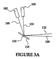
図3Aおよび3Bを参照すると、光線120、122、124を同一直線に存在させるための制御装置142の操作が議論される。議論を簡潔にするために、2本のレーザー102、104だけを図3に図解したが、当業者は、本明細書に記載される概念が、本発明の精神および範囲から逸脱することなく、3本以上のレーザーに拡張され得ることを認識する。図3Aに示したように、レーザー102、104を同時に活性化する場合、反射光線120、122は発散する。しかしながら、図3Bに示したように、レーザー102、104がわずかに異なる時間で活性化されると、光線120、122は、単独の、共通の経路をたどるようになり得る(すなわち、光線120、122は同一直線に存在する)。たとえば、レーザー102が第1時間t1において活性化されると、鏡118は実線で表された第1の位置にあり、光線108は鏡118から光線120として反射する。続いて、レーザー104が第2時間t2において活性化されると、鏡118は破線で表した第2の位置にあり、光線110は鏡118から光線122として反射する。時間t2を精確に制御することによって、鏡118は光線122を、光線120と実質的に同一な経路に沿って、正確に反射するための配置に存在する。
With reference to FIGS. 3A and 3B, the operation of the
従って、制御装置142の操作を介して、光線120、122は実質的に同一な直線上に存在するが、時間においてわずかにずらされている。すなわち、光線120、122はどちらも画面138上の実質的に同一な点に投影されるが、わずかに異なる時間に投影される。しかしながら、人間の目の残光持続性の影響で、タイミングの差異は検知不可能である。すなわち、図1に記載された3本のレーザーシステムの場合、各レーザー102、104、106は、比較的短い時間帯で画面138上の実質的に同一な点に、単色のレーザー光および強度を制御可能に伝える。人間の目は3つの別個な色を検知できないが、むしろ、不変で好ましい色調が画面上のその点に現れるように3つの光線の混合されたものを知覚する。当業者は、この過程が、画面138上に像を再現するために、経路140に沿って何度も繰り返され得ることを認識する。
Thus, through operation of the
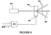
上記したように、レーザー102、104、106は画像を表示するために制御され得る。レーザー102、104、106の制御は、レーザー光の制御可能な移動および変調を含む。図4を参照すると、本発明に使用され得る変調スキームの一実施形態が示される。音響光学の結晶400はレーザー402の前に配置される。変調装置404は画像データをRF信号に変換し、その信号は結晶400に結合された圧電アクチュエーター406を駆動する。回折格子内で転向する、圧電アクチュエーター406から生じた音響波は結晶400を介して伝播し、音響波の強度によって、主ビーム408からの光学的エネルギーの一部を、複数の副ビーム410に発散させ、したがってビーム408は画像データにより変調される。
As described above, the
レーザー光の強度も図5に示される回路網により制御され得る。KerrセルまたはPockelsセルのような電気光学装置500はレーザー502の前に配置される。電気光学装置500は、通過する光の偏光を回転させる特性を持つ。変調装置504は画像データを電気信号に変換し、その信号は電極506に印加される。電極506に印加される電気信号は、電極506に印加される電圧の大きさによって、レーザービーム508の偏光を回転させる。電気光学装置500から抜け出ると、レーザービーム508は偏光子510に伝達される。偏光子510の偏光の方向は、レーザー502の偏光の方向と一致するように選択される。したがって、偏光子510を通過する光の量は、ビーム508の偏光がどのくらい元の方向と異なるかに依存し、それゆえにビーム508の強度は画像データにより変調される。
The intensity of the laser light can also be controlled by the network shown in FIG. An electro-
あるいは、レーザーの変調が図6に示される回路網により達成され得る。本発明の一実施形態において、レーザー600からのIR光は、周波数2倍結晶602によって短波長の光(たとえば、緑または青)に変換され得る。電極604を介して結晶602に電圧を印加すると、結晶602内部で、入力IRビーム606と出力可視ビーム608との間の位相整合状況が変化し、したがって変換効率および出力パワーが変化する。変調装置610は画像データに従う電圧を発生させる。さらに、バイアス発生装置612は、結晶602上のバイアス電圧を、結晶602内の温度変化の補正および最良の位相整合状況の保存のために変化させ得る。
Alternatively, laser modulation can be achieved by the circuitry shown in FIG. In one embodiment of the invention, IR light from
図7は、レーザー光を変調するために使用され得る回路網の他の実施形態を図解する。ビームスプリッター700は、レーザー704からの光線702を2つの副ビーム706、708に分割する。ビーム706はビームコンバイナー710に向かって直進するが、ビーム708は光学遅延素子712(例えば、マイクロマシン化された、または電気光学的な)を通過し、画像データに従う変調装置714により制御される遅延を導入する。ビーム706、708がコンバイナー710によって再結合される際、出力ビーム716の強度はビーム706、708間の位相相関に依存して変化する。2本のビームが同位相の(すなわち、ゼロ遅延がビーム708に適用される)場合、出力ビーム716の強度は最も高くなる。2本のビームが逆位相の(すなわち、ビーム708が半周期遅延される)場合、出力強度はゼロになる。
FIG. 7 illustrates another embodiment of circuitry that can be used to modulate laser light. The
レーザー光の変調も、図8に展示した回路網により与えられる。レーザー800は、電源802から第1電流供給源804を介して一定のバイアス電流を供給される。電流供給源804は制御装置806により制御され、その制御装置は、増幅器810を介して伝えられる、レーザー光ダイオード808からのフィードバック信号と、予め選択されたレベルとを周期的に比較する。第2電流供給源812は、流入する画像データに従い、変調装置814によって制御され、その電流は第1電流供給源804からの電流に加えられる。第1電流供給源804は、第2電流供給源812からの電流が実質的にゼロの場合、レーザー800が放射しきい値の真上に存在するという方法により調節される。第2電流供給源812は、画像データが最大強度を要求する際、供給源804、812からの結合電流によって駆動されたレーザー800が全出力で放射されるという方法により調節される。適切なキャリブレーション達成のために、フレームの専用部分が変調から免れ得る。
The modulation of the laser light is also given by the network shown in FIG. The
あるいは、図9に示したように、第2供給源からの電流は、第1供給源804からの電流に加えられるというよりはむしろ、その電流から差し引かれる。この場合、第1電流供給源804は、第2供給源812からの電流がゼロの際、レーザー800が全出力で放射されるという方法によって調節される。第2供給源812からの電流は画像データの値に反比例する。したがって、画像データがゼロ強度を要求する際、第2供給源812からの電流は最大になり、レーザー800は放射しきい値の真上に存在する。
Alternatively, as shown in FIG. 9, the current from the second source is subtracted from the current rather than being added to the current from the
あるいは、変調装置814も、画像データがゼロ強度を要求する際(図10)、第1電流供給源804を完全に切断することが可能であり得る。この場合、バイアス電流がレーザー800を介して流れず、そのため電力が保存され得る。
Alternatively, the
図11を参照すると、さらに他の代案が、パルス幅変調モードにおいて作用する変調装置814とともに図解される。光ダイオード808、増幅器810および制御装置806からなるフィードバックループは、電流が有効になる際、レーザー800が全出力で放射されるという方法によって、いまだに供給源804の電流を調節する。PDM変調装置814は画像データに比例する時間において、電流のオンまたはオフを切り換える。
Referring to FIG. 11, yet another alternative is illustrated with a
図12において示される、さらなる他の代替的な実施形態において、出力電圧がレーザー800上でドロップアウト電圧の変化をたどるという方法において、電源802が、可変電圧を伝達することが可能で、増幅器1200および制御装置1202によって制御される場合、レーザー変調システムの電力効率が向上され得る。
In yet another alternative embodiment, shown in FIG. 12, in a way that the output voltage follows a change in dropout voltage on
当業者は、図8〜12に表された種々の回路が、本発明の精神および範囲から逸脱することなく、グランドケースレーザーの代わりにホットケースレーザーを適応するように容易に修正され得ることを認識する。 Those skilled in the art will recognize that the various circuits depicted in FIGS. 8-12 can be readily modified to accommodate a hot case laser instead of a ground case laser without departing from the spirit and scope of the present invention. recognize.
図13を参照して、上記した通り、システムは、2枚の鏡1304、1306を通るレーザー1302からの集束ビームにより、スクリーン1300上に画像を表示させるように配置される。本発明の一実施形態において、スクリーン1300は蛍光被覆のスクリーン1300という形態をとり得る。本発明の一実施形態において、スクリーン1300はアップコンバーティング蛍光体(入射光線よりも短波長の光を放射する物質)によって被覆され得る。この場合、レーザー1302は赤外線レーザーの形態をとり得る。あるいは、青または紫外線のレーザーが、「標準な」ダウンコンバーティング蛍光体をスクリーン1300に適用させる状態で使用され得る。
Referring to FIG. 13, as described above, the system is arranged to display an image on a
フルカラー画像は、三原色に対応する発光波長をもった3つの蛍光体の合成により被覆されたスクリーンを用いることにより作られ得、3本のレーザー1400、1402、1404は、3本のレーザーの吸収帯から放射され、各レーザーが一原色に対応して画像を描く(図14)。蛍光体は任意の組み合わせにおいてアップコンバーティング、ダウンコンバーティングのどちらでもよい。また、1つ以上の色がレーザーにより直接描かれ得る。例えば、スクリーン1300は、約808nmの吸収ピークおよび約460nmの放射ピークを持つアップコンバーティング蛍光体(青色)と、約405nmの吸収ピークおよび約550nmの放射ピークを持つダウンコンバーティング蛍光体(緑色)の混合体により被覆され得る。画像の赤色部分は635nmの可視レーザーによって直接描かれ得、そのレーザーは蛍光体との相互作用なしにスクリーンから反射される。青色部分は808nmのIRレーザーにより描かれ、一方で緑色部分は405nmの紫色レーザーにより描かれる。
A full color image can be created by using a screen coated by the synthesis of three phosphors with emission wavelengths corresponding to the three primary colors, the three
あるいは、図15に示されるように、スクリーン1300は、三原色に対応する発光波長および近接した吸収波長を持つ異なる蛍光体のドット1500または線1502を含み得る。全部で3つの蛍光体が、共通の吸収波長において、1本のレーザー放射により励起され得、一方で画像の色要素は、それぞれの色画素または色線を交差する間にレーザーの強度を変調することで、表現される。
Alternatively, as shown in FIG. 15, the
レーザービームは発振または回転する鏡によって走査され得、鏡は多角形を含む、多様な形態をとり得る。レーザービームも、レーザーに対して1つのレンズまたは複数のレンズのアレイを直線的に移動させることによって、またはレンズに対して1つのレンズまたは複数のレンズのアレイを直線的に移動させることによって走査される。 The laser beam can be scanned by an oscillating or rotating mirror, which can take a variety of forms, including polygons. The laser beam is also scanned by linearly moving one lens or an array of lenses relative to the laser, or by linearly moving one lens or an array of lenses relative to the lens. The
ブレーズド回折格子(図16A)は、回折格子のパラメーターが式1を満たす際は、実質的に完璧な鏡として作用する。一般的に、回折格子の近接する2本の線の端から反射された光の位相遅延が波長の倍数に等しい際に発生する。実質的に類似した状況が、アレイピッチが固定される間に、転向および同時に上方または下方移動する微小鏡のアレイによって任意の走査角度が観察され得る(図16B)。
The blazed diffraction grating (FIG. 16A) acts as a substantially perfect mirror when the diffraction grating parameters satisfy
あるいは、実質的に類似な効果が、小さな鏡のアレイによって達成され得、その鏡は上下方向のみに移動するが(図16C)、鏡の大きさは可視光の波長と同等である(Silicon Light MachineのGLVと同様)。 Alternatively, a substantially similar effect can be achieved with an array of small mirrors that move only up and down (FIG. 16C), but the mirror size is equivalent to the wavelength of visible light (Silicon Light). Same as Machine's GLV).
特定の結晶に音響波を誘導すると、音響波の波長と同等の周期を持つ回折格子に向かうように転向される。それゆえ、レーザービームは、音響周波数を変化させる間にそのような結晶にレーザービームを通過させることによって走査され得る。 When an acoustic wave is induced in a specific crystal, it is turned toward a diffraction grating having a period equivalent to the wavelength of the acoustic wave. Thus, the laser beam can be scanned by passing the laser beam through such a crystal while changing the acoustic frequency.
走査鏡の絶対的な位置に関する情報は、間接的に抽出され得る。例えば、図18に示したように、圧電要素1800は、鏡1802を走査する力を生成するために使用され得る。圧電要素1800によって発生させられた電圧を測定することにより、生じた力の量および、それゆえに鏡1802の角度の移動が得られ得る。図解された実施形態において、圧電要素1800は基部1804上に備え付けられ、ヒンジ1806により発生させられた力を受ける。鏡1802の偏向角は通常、ヒンジが発生させるトルクに比例するので、圧電要素1800からの電圧も偏向に比例する。圧電要素1800は本質的にコンデンサーであり、インピーダンスは極めて高くなり得(特に低周波数においては)高い入力インピーダンスによる信号調整装置1808が有用であり得る。
Information about the absolute position of the scanning mirror can be extracted indirectly. For example, as shown in FIG. 18, the
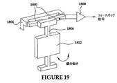
当業者は、本発明における代替的な実施形態において、圧電要素1800は、図19に示されるように曲げ型の形態をとり得ることを認識する。
Those skilled in the art will recognize that, in alternative embodiments of the present invention, the
位置センサーも走査鏡の位置を検知するために使用され得る。図20に示されるように、比較的小さな磁石2000は鏡1802に取り付けられ得、定常コイル2002は鏡1802の角速度を決定するために使用され得る。すなわち、コイル2002における電圧は、合理的に小さな走査角の場合に速度に比例する。速度は、鏡の位置の導関数なので、位置は速度フィードバック信号を積分することで決定され得る。当業者は磁石2000およびコイル2002の位置および移動が、本発明の精神および範囲を逸脱することなく逆転され得ることを認識する。すなわち、コイル2002は、永久磁石2000が静止しているときは鏡1802上に存在し得る。
A position sensor can also be used to detect the position of the scanning mirror. As shown in FIG. 20, a relatively
あるいは、外部の永久磁石によって磁化された、軟磁性体の比較的小さな要素は、本発明の精神および範囲を逸脱することなく、使用され得る。 Alternatively, relatively small elements of soft magnetic material magnetized by an external permanent magnet can be used without departing from the spirit and scope of the present invention.
図21を参照して、鏡の位置も鏡1802上に配置された電極2100と、その電極と間隔を空けて配置された静止電極2102との間の静電容量を測定することにより決定され得る。電流供給源2104からの電流は印加され得、結果として抵抗体2106を横切ってドロップアウトする電圧は、鏡の位置の示度として計測され得る。当業者は、鏡1802自体が導電性の場合、電極2100が必要でなくあり得ることを認識する。
Referring to FIG. 21, the position of the mirror can also be determined by measuring the capacitance between
図22に示した通り、鏡の位置も、鏡1802によって反射され光検知器2202に向かう、光源2200からの光量を測定することにより決定され得る。特に有利な光学的配置が、図23Aおよび23Bに上面図および側面図として示され、光源2200および検知器2202のFOVがレンズ2300により平行にさせられる。この場合、検知器2202は鏡1802の表面が、レンズ2300からの平行な光線の方向に実質的に垂直である際に、はっきりした光パルスを検知する。
As shown in FIG. 22, the position of the mirror can also be determined by measuring the amount of light from the
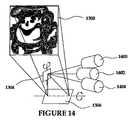
異なる傾斜角および光学倍率を有する、種々のレンズ群1700または鏡群1702は、LPD投影機1704のFOV内に配置され得、従って、様々な大きさおよび分解能の複合画像を生成する。例えば、遠くに小さくて高分解能な画像1706、近くに大きくて低分解能の画像1708が発生され得る(図17)。LPD制御装置は、光学素子の位置について認識している必要があり、従って、各画像に対して意図された画像データを処理する必要がある。
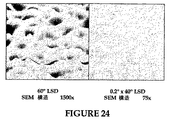
いくつかの適用において、多種の特別に設計されたスクリーンを使用するために有用であり得る。例えば、LPDスクリーンにより発散させられた光は、特別に設計されたスクリーンとの角度が180度より狭くなるように方向付けられ得る。スクリーンは回折またはホログラフィックなパターンを有し得、そのパターンは、光が制御可能な角度に反射(反射投影)または発散(透過投影)することを保証する(図24)。あるいは、スクリーンは、透過投影においては、複数の屈折レンズ2500のアレイ(図25A)、または反射投影においては、複数の鏡2502(図25B)からなり、光を比較的狭い角度に方向付ける。 In some applications, it may be useful to use a variety of specially designed screens. For example, the light diverged by the LPD screen can be directed such that the angle with the specially designed screen is less than 180 degrees. The screen may have a diffractive or holographic pattern that ensures that the light is reflected (reflective projection) or diverged (transmission projection) at a controllable angle (FIG. 24). Alternatively, the screen consists of an array of refractive lenses 2500 (FIG. 25A) in transmission projection, or a plurality of mirrors 2502 (FIG. 25B) in reflection projection, directing light at a relatively narrow angle.
図26に示したように、複数のレンズは、スクリーン上の全ての点からの光を、光が入射してくる方向にかかわりなく、同一の方向に向ける構造2600を形成するためにプリズムと結合され得る。この結合により、一様な視角を広い走査角のLPDが獲得できる。類似のアイデアも反射投影スクリーンにおいて鏡、または発散式スクリーンを用いてインプリメントされ得る。
As shown in FIG. 26, multiple lenses combine with a prism to form a
典型的に、位相同期ループ回路は、電圧制御発振器(VCO)2700、ディバイダー2702、位相検知器2704および増幅器2706からなり、それらは外部基準信号に、VCO出力信号の周波数および位相を同期するために作用する(図27A)。外部基準信号の周波数に前もって同期された周波数の信号が既に存在する場合、位相は電圧制御遅延回路2708とVCOを交換することにより同期され得る(図27B)。
Typically, the phase locked loop circuit consists of a voltage controlled oscillator (VCO) 2700, a
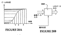
LPDにおいて共振鏡が使用される場合、走査プロフィールは、線形以外になり得、正弦であり得る場合もある。それゆえに、ビームは、図28Aに図式的に示したように、クロックティック(clock tick)毎に様々な距離を移動する。鏡の移動の非線形特性を補正するために、元の画像1ピクセルのデータを、現在の鏡の位置に依存するLPD出力データの数クロックティック分に割り当てる、ルックアップテーブル2800(図28B)が使用され得る。 When a resonant mirror is used in LPD, the scanning profile can be non-linear and can be sinusoidal. Therefore, the beam travels various distances every clock tick, as schematically shown in FIG. 28A. A lookup table 2800 (FIG. 28B) is used to allocate one pixel data of the original image to several clock ticks of LPD output data depending on the current mirror position to correct for the non-linear characteristics of mirror movement. Can be done.
レーザービームにより、スクリーン上の特定の点まで伝達された光の量は、ビームが移動する速度に反比例するので、レーザーの動力も比例的に減少させるべきである。この機能も図28Bに示されるルックアップテーブルに類似したルックアップテーブルの配置により達成され得る。 Since the amount of light transmitted by a laser beam to a particular point on the screen is inversely proportional to the speed at which the beam travels, the power of the laser should also be reduced proportionally. This function can also be achieved by arrangement of a lookup table similar to the lookup table shown in FIG. 28B.
図29Aは、従来のCRTにおける典型的な電子ビーム走査経路を様式的に図解する。通常、電子ビームは、画面を横切る一方向にゆっくりと移動させられ、その後素早く後方に戻される。普通、データは前方横断においてのみクロックされる。しかしながら、本発明のLPDにおいて、LPDは、図29Bに示されたレーザービーム経路の様式的な説明によって描かれるように、両方向において同一速度で走査する。それゆえ、データは前方および後方走査の間に供給されるが、データのすべてのセカンドラインは、走査が逆転した方向で行われるので、逆転される必要がある。このデータの逆転は、図29Cに示したように双方向シフトバッファー2900を用いる本発明の一実施形態において達成される。画像データは、同じ順序において元の画像内に配置されるようにシフトバッファー2900へロードされる。例えば、左から右へ。フリップフロップ2902は各線上できっかけとなり、従って、バッファー2900のシフト方向を変化させ、その変化により逆転走査上でデータの逆転を順応させる。
FIG. 29A schematically illustrates a typical electron beam scanning path in a conventional CRT. Usually, the electron beam is slowly moved in one direction across the screen and then quickly returned backwards. Normally, data is clocked only at the forward traversal. However, in the LPD of the present invention, the LPD scans at the same speed in both directions, as depicted by the stylistic description of the laser beam path shown in FIG. 29B. Therefore, data is supplied during forward and backward scans, but all second lines of data need to be reversed because the scan is in the reversed direction. This data reversal is achieved in one embodiment of the present invention using a
本発明のいくつかの実施形態において、駆動電流が閉ループ制御により調節される場合、一方向に一定の速度で移動するように走査鏡に強制することは有用であり得、一方で、独自の共振速度によって後方にジャンプする(図30、曲線2)。図30の曲線1は、基準用の正常な正弦走査プロファイルを示す。
In some embodiments of the present invention, it may be useful to force the scanning mirror to move at a constant speed in one direction when the drive current is adjusted by closed loop control, while having its own resonance Jump backwards depending on the speed (Fig. 30, curve 2).
図31に図解した実施形態において、鏡3100は組み込みのフィードバックユニット3102を有し、そのユニットは、鏡3100の速度および位置情報双方を抽出することが可能である。このようなフィードバックは上記した通り、圧電的またはその他であり得る。各定速サイクルの開始時に、鏡の制御装置3104は望ましい速度を設定し、その速度は誤差増幅器3106により速度フィードバックと比較される。誤差増幅器3106の出力端子は、鏡のドライバー3108に接続され、ドライバー3108の出力電流は、制御装置3104により設定された値に対する鏡の速度の偏差が最小になるように、連続的に調節される。制御装置3104も鏡の終端位置を設定し、その位置はコンパレーター3110によって速度フィードバックと比較される。鏡3100が終端位置に到着するや否や、コンパレーター3110はドライバー3108の出力信号を高インピーダンス状態に切り換え、そのため、鏡3100はヒンジのトルクの下で、揺れ戻る。反対の終端位置に到着すると、コンパレーター3110はドライバー3108を元の状態に切り換え、新たなサイクルが開始される。
In the embodiment illustrated in FIG. 31, the
あるいは、図31Bに示されたように、ドライバー3108は制御装置3104の全制御下にあり得、相応のフィードバック信号の処理およびドライバー3108の調節を行う。この場合、ドライバー3108の連続的な調節の代わりに、制御装置3104は所定のサイクルを繰り返し得、一方でサイクル間に小さな変化を生じさせる。随意的に、制御装置3104は、ホスト制御装置からの垂直同期パルスと同期され得る。
Alternatively, as shown in FIG. 31B, the
図32から図36を参照して、レーザー投影ディスプレイの視野性能を向上させるために有用であり得る、本発明の様々な実施形態を示す。例えば、図32に示された実施形態において、LPD3200は、LPD3200から放射されたレーザー光の特別な波長に対して相互作用するように設計され、特別に構築されたスクリーン3202上にレーザー光を投影するように配置される。本発明の一実施形態において、LPD3200は、それぞれ緑色光、赤外光および紫外光を放射する3本のレーザーを用いて構築され得る。マルチカラーディスプレイを構築するために一般に使用される伝統的な(赤色、青色および緑色の)光を得るために、スクリーン3202は、赤外光を赤色光に変換(アップコンバート)および紫外光を青色光に変換(ダウンコンバート)する物質によって構築される。
Referring to FIGS. 32-36, various embodiments of the present invention that may be useful for improving the viewing performance of a laser projection display are shown. For example, in the embodiment shown in FIG. 32, the
スクリーン3202の構築に使用され得る物質の一形式は、既知の光輝性物質である。例えば、スクリーン3202は、第2の予め選択された波長を有する光により照射された際に、第1の予め選択された波長の光を発光する、または放射することによって反応する蛍光体で少なくとも部分的に処置または被覆され得る。従って、当業者はLPD3200において赤外レーザーが、赤色光の成分を有することを意味するスクリーンの一部分を照射するために制御され得ることを認識する。赤外光によって照射される範囲のスクリーン3202上に配置される蛍光体は、赤色光を発光および放射することにより赤外光に応答する。同様に、紫外光によって照射される範囲のスクリーン3202上に配置される蛍光体は、青色光を発光および放射することにより紫外光に応答する。従って、スクリーン3202を見ている人物は、美的に心地よいマルチカラーディスプレイを生成するために、スクリーン上の様々な場所で、赤、青および緑色の光の好ましい配合を知覚する。
One type of material that can be used to construct the
本発明の代替的な実施形態において、LPD3200は、それぞれ緑色光、赤色光および370〜405nmの範囲内の光を放射する3本のレーザーを用いて構築され得る。370〜405nmの範囲のレーザー光は、例えば従来的な白いスクリーン(紙で構築されている)に投影された際は、青の冷光を発する(photoluminesce)傾向がある。従って、この代替的な実施形態において、簡略化したスクリーン3202は、赤色および緑色のレーザー光が白い紙製のスクリーンによって反射され、370〜405nmの光は青い冷光を発するので、従来的なマルチカラーディスプレイを依然として提供しながら使用され得る。
In an alternative embodiment of the present invention,
当業者はこれら2つの実施形態の側面が、種々の中間実施形態を発生させるために結合され得ることを認識する。例えば、LPD3200は、緑色光、赤外光および370〜405nmの範囲の光をそれぞれ放射する3本のレーザーを用いて構築され得る。スクリーン3202の、少なくとも一部は、370〜405nmの光を青く冷光させる(紙のような)従来的な白い物質で構築され得る。さらにスクリーン3202は、赤外レーザー光で照射された際に、赤色光を放射する蛍光体で少なくとも部分的に被覆され得る。
Those skilled in the art will appreciate that aspects of these two embodiments can be combined to generate various intermediate embodiments. For example, the
さらに、当業者は、縮小されたマルチカラーの能力を有するシステムが、赤色と青色の光、青色と緑色の光、または赤色と緑色の光の組み合わせのみを発生する2本のレーザーシステムを用いることで発生させ得ることを認識する。 In addition, those skilled in the art will use a two laser system where a system with reduced multi-color capability generates only red and blue light, blue and green light, or a combination of red and green light. Recognize that can be generated by.
いくつかの適用において、広く「グローインザダーク(glow in the dark」として知られる実質的な残光持続性を示す蛍光体物質を使用することは有用であり得る。一旦照射されると、これらの物質はイルミネーションが除去された後においても比較的長期間発光することが知られている。これらの物質の残光持続性は、標識にとって有用なスクリーンまたはより高い分解能のスクリーンを生成することにとって有用であり得る。物質の残光持続性は通常、頻繁に照射される必要がないことを意味し、任意の顕著な「閃光」なしにゆっくりとしたリフレッシュ速度を可能にする。ゆっくりとしたリフレッシュ速度は通常、LPDが、より密接してぎっしり詰められた多くの走査線を有するようにプログラムされ得ることを意味する。当業者は、より多くの走査線が、高分解能へと変換されることを容易に認識する。 In some applications, it may be useful to use a phosphor material that exhibits substantial persistence of persistence, commonly known as “glow in the dark.” Once irradiated, these Materials are known to emit light for a relatively long time after the illumination is removed, and the persistence of these materials is useful for producing screens useful for labels or higher resolution screens. The persistence of the material usually means that it does not need to be irradiated frequently, allowing a slow refresh rate without any noticeable “flash”. Usually means that the LPD can be programmed to have many scan lines more closely packed. That. Those skilled in the art, the more scan lines readily recognize that it is converted to high resolution.
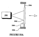
図33Aおよび33Bを参照すると、レーザースペックルを減少するように配置されたスクリーン3302を照射する、LPD3300が図解される。スクリーン3302のとてもわずかな移動または発振がレーザースペックルを消去または少なくとも減少する傾向にあることが観測される。従って、図33Aに図解した本発明の第1の実施形態において、スクリーン3302は移動を制限するためにフレーム3306と結合される。移動を制限することは、例えば、フレーム3306とスクリーン3302との間で伸長している複数のバネ3304によって達成され得る「ゆるい」結合により提供される。線形アクチュエーターのようなアクチュエーター3308も、アクチュエーターが時間変化する信号により励起させられる際にスクリーン3202を振動または移動させるように、スクリーン3302と結合される。スクリーン3202に引き起こされる振動は小さく、スクリーン3302を見ている人物にとって容易に明白でない可能性もある。
Referring to FIGS. 33A and 33B, an
図33Bに図解された代替的な実施形態において、2層のスクリーン3310が図解される。この実施形態において、スクリーン3310は、LPD3300からのレーザー光を受け、背面投影スクリーン3314上にレーザー光の焦点を合わせるフレネルレンズのようなレンズ3312を含む。画像はスクリーン3314上に形成され、スクリーン3314の前に配置された位置3316から人物が見る。本発明のこの実施形態において、スペックルはレンズ3312を移動または振動させることにより減少または実質的に排除され得る。この様式において、スクリーン3314は、レンズ3312が非常にわずかな振動をしている間に、実質的に静止したままである。フレーム3318はスクリーン3314に固定して結合され、レンズ3312には移動可能に結合される。本発明の一実施形態において、移動可能な結合は、フレーム3318とレンズ3312との間に伸びている1つ以上のバネ3320により達成され得る。図33Aに図解された実施形態のように、アクチュエーター3308は、アクチュエーター3308が時間変化する信号によって励起された際にレンズ3312を振動または移動させるようにレンズ3312に結合される。
In the alternative embodiment illustrated in FIG. 33B, a two
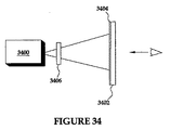
図34は、コントラストを強調するために偏光を使用するLPDシステムを様式的に図解する。図解された実施形態において、LPD3400が、スクリーン3402の後部面上にレーザー光を投影する様子を図解される。偏光フィルム3404は、LPD3400からのレーザー光がスクリーン3402上に表示される前に偏光フィルム3404を通過するように、スクリーン3402の後部面に近接して配置される。LPD3400から放射されたレーザー光も偏光フィルム3404の方向に整合するような様式で偏光される。LPD3400により発生させられた偏光されたレーザー光の再配向は、必要に応じて、レーザー光の光学的経路に半波長プレート3406を挿入するなどの種々の周知の手法のうちの任意の手法を用いることで達成され得る。偏光フィルム3404の方向に整合するように偏光されたレーザー光によって、実質的に全ての入射レーザー光は、偏光フィルム3404を通過してスクリーン3402上に表示される。しかしながら、任意の周辺光または散乱したレーザー光は偏光フィルム3404の方向に整合するようには偏光されず、従って、この好ましくない周辺光または散乱光の実質的に半分が偏光フィルム3404によって遮断される。従って、入射レーザー光が実質的に全出力である間、妨害する周辺または散乱光が実質的に減少され、実質的に強調されたコントラストを提供する。
FIG. 34 stylizes an LPD system that uses polarized light to enhance contrast. In the illustrated embodiment, the
図35Aを参照して、単色レーザーまたは白黒レーザーLPD3500が限定されたマルチカラーディスプレイを提供するように図解される。スクリーン3502は、共通の光源により照射された際に多種の色の光を発光または放射する、蛍光体のような光輝性物質によって処置される。すなわち、各蛍光体は、同一の白黒レーザー光により照射されたことに応答して、独自の区別可能な色で発光する。スクリーン3502は、白黒レーザー光により照射された際に青色に発光する蛍光体によって被覆または処置された第1範囲3504を有するように構築され得る。同様に、スクリーン3502は、白黒レーザー光により照射された際に赤色に発光する蛍光体によって被覆または処置された第2範囲3506を有するように構築され得る。範囲3508、3510は、それぞれ緑色および黄色に発光するように、同様に構築され得る。
Referring to FIG. 35A, a single color laser or black and
図35Bは、自動車に適用される際に有用であり得るスクリーン3502の一実施形態を図解する。種々のゲージ、警告灯、娯楽アイテムおよびその他が、種々の蛍光体を用いてスクリーン3502上に構築または描かれ得る。例えば、警告灯3512は照射された際に赤色に発光する蛍光体を用いてスクリーン3502上に構築され得、他方で速度計3514および回転計3516、燃料計3518およびその他のようなゲージは青色または緑色に発光する蛍光体を用いて構築され得る。従って、白黒レーザーLPD3500はスクリーン3502の種々の部分を照射するように制御される際、蛍光体は適切な色で発光し、自動車の運転者に有用な情報を提供し、その色は、情報および/または緊急事項の形式を示す。
FIG. 35B illustrates one embodiment of a
そうではないと具体的に述べられていない場合は、または議論から明らかな場合、「処理する」、「演算する」、「計算する」、「決定する」、「表示する」またはその他同様の用語は、コンピューターシステムのレジスターおよびメモリー内の物理的、電子的な量として表されるデータを、コンピューターシステムのメモリーまたはレジスターまたはその他の情報記憶装置、伝送またはディスプレイ装置のようなものの内部における物理量として同様に表されるその他のデータに、操作および変換する、コンピューターシステム、または同様の電子演算装置の動作および処理のことをいう。 If not specifically stated otherwise, or apparent from the discussion, "process", "calculate", "calculate", "determine", "display" or other similar terms Is similar to a physical quantity in a computer system's registers and memory, represented as a physical quantity in a computer system's memory or register or other information storage device, such as a transmission or display device. Refers to the operation and processing of a computer system or similar electronic computing device that manipulates and converts to other data represented in.
当業者は、本明細書中の様々な実施形態に図解される様々なシステムレイヤー、ルーチンまたはモジュールが、実行可能な制御ユニットであり得ることを認識する。制御ユニットはマイクロプロセッサー、マイクロコントローラー、デジタル信号処理装置、処理装置カード(1つ以上のマイクロプロセッサーまたは制御装置を含む)、または、その他の制御装置または演算装置を含み得る。本議論でいう記憶装置とは、1つ以上の機械読み取り可能な、データおよび命令を記憶するための記憶装置媒体を含み得る。記憶装置媒体は、動的または静的ランダムアクセスメモリー(DRAMまたはSRAM)、消去可能でプログラム可能な読み取り専用メモリー(EPROM)、電気的に消去可能でプログラム可能な読み取り専用メモリー(EEPROM)およびフラッシュメモリーのような半導体メモリー装置;固定ディスク、フロッピー(登録商標)ディスク、リムーバブルディスクのような磁気ディスク;磁気テープを含むその他の磁気媒体;およびコンパクトディスク(CD)またはデジタルビデオディスク(DVD)のような光学的媒体、を含むメモリーの様々な形態を含み得る。種々のシステムにおける種々のソフトウェアレイヤー、ルーチン、またはモジュールを作り上げる命令はそれぞれの記憶装置に記憶され得る。制御ユニットにより実行された際、命令は対応するシステムに、プログラムされた行動を実行させる。 Those skilled in the art will recognize that the various system layers, routines or modules illustrated in the various embodiments herein may be executable control units. The control unit may include a microprocessor, microcontroller, digital signal processor, processor card (including one or more microprocessors or controllers), or other controller or computing device. As used in this discussion, a storage device may include one or more machine-readable storage media for storing data and instructions. Storage media includes dynamic or static random access memory (DRAM or SRAM), erasable programmable read only memory (EPROM), electrically erasable programmable read only memory (EEPROM) and flash memory Semiconductor memory devices such as: fixed disks, floppy disks, magnetic disks such as removable disks; other magnetic media including magnetic tape; and compact disks (CD) or digital video disks (DVD) Various forms of memory including optical media may be included. The instructions that make up the various software layers, routines, or modules in the various systems may be stored in respective storage devices. When executed by the control unit, the instructions cause the corresponding system to execute the programmed action.
上記に開示された特定の実施形態は例示に過ぎず、本発明は、改変され得、本明細書の教示の利益を有して、当業者にとって明らかである同等であるが異なる形態で実行され得る。さらに、添付の特許請求の範囲を除いて、本明細書に示されている構築物または設計の詳細へと制限する意図はない。結果的に、本開示の利益をもって、当業者によって理解されるように、記載したシステムをインプリメントおよび使用するために必要な処理回路網は、特定用途向け集積回路、ソフトウェア駆動処理回路網、ファームウェア、プログラマブルロジックデバイス、ハードウェア、上記構成要素の個別の部品または配置において、インプリメントされ得る。従って、上記で開示した特定の実施形態が変更または改変され得、このような全ての変形物が本発明の範囲および精神内であると考慮されることは、明らかである。従って、本明細書で求める保護を添付の特許請求の範囲において記載する。 The specific embodiments disclosed above are exemplary only, and the invention may be modified and carried out in equivalent but different forms, which will be apparent to those skilled in the art, with the benefit of the teachings herein. obtain. Furthermore, there is no intention to limit to the details of construction or design shown herein, except as appended claims. Consequently, as would be understood by one of ordinary skill in the art with the benefit of this disclosure, the processing circuitry required to implement and use the described system includes application specific integrated circuits, software driven processing circuitry, firmware, It can be implemented in a programmable logic device, hardware, separate parts or arrangements of the above components. It is therefore evident that the particular embodiments disclosed above may be altered or modified and all such variations are considered within the scope and spirit of the invention. Accordingly, the protection sought herein is set forth in the appended claims.
本発明は、添付する図面と関連させて以下の記載を参照することにより理解され得、図面中の類似する参照数字は類似する要素を識別する。
Claims (23)
第1の予め選択された方向に偏光されたレーザービームを伝達するように適合されたレーザー投影装置と、
該レーザービームを受け該レーザービームの実質的な部分が通過するように適合された偏光子と、
該偏光子を通過する該レーザービームの該部分を受けるように適合されたスクリーンと
を備える、装置。 An apparatus for displaying an image,
A laser projection device adapted to transmit a laser beam polarized in a first preselected direction;
A polarizer adapted to receive the laser beam and pass a substantial portion of the laser beam;
And a screen adapted to receive the portion of the laser beam that passes through the polarizer.
第1の偏光方向に、該レーザー投影装置により投影されたレーザー光を配置することと、
該レーザー投影装置により投影された該レーザー光の該偏光方向に実質的に類似する方向を有する偏光子を該レーザー光の少なくとも実質的な部分が通過することと、
該偏光子を通過した該レーザー光をスクリーンに伝達することと
を含む、方法。 A method for displaying an image with a laser projector,
Disposing the laser light projected by the laser projector in a first polarization direction;
Passing at least a substantial portion of the laser light through a polarizer having a direction substantially similar to the polarization direction of the laser light projected by the laser projector;
Transmitting the laser light that has passed through the polarizer to a screen.
フレームと、
該フレームと柔軟に結合されたスクリーンと、
該スクリーンと結合され該スクリーンにおける移動を誘発するアクチュエーターと
を含む、システム。 A laser projection system that controllably reduces laser speckle,
Frame,
A screen flexibly coupled to the frame;
An actuator coupled to the screen to induce movement in the screen.
スクリーン上にレーザー光を投影することと、
該スクリーンを制御可能に移動することと
を含む、方法。 A method for controllably reducing laser speckle,
Projecting laser light onto the screen;
Moving the screen in a controllable manner.
第1の予め選択された周波数の第1のレーザービームを伝達するように適合されたレーザー投影装置と、
該レーザービームにより照射されることに応答して該第1の予め選択された周波数の光を放射するように適合された第1の光輝性物質と、該レーザービームにより照射されることに応答して第2の予め選択された周波数の光を放射するように適合された第2の光輝性物質とを有するスクリーンと
を備える、装置。 An apparatus for displaying an image,
A laser projection device adapted to transmit a first laser beam of a first preselected frequency;
In response to being irradiated by the laser beam, in response to being irradiated by the laser beam, and a first photoluminescent material adapted to emit light of the first preselected frequency. And a screen having a second photoluminescent material adapted to emit light of a second preselected frequency.
第1の予め選択された周波数の第1のレーザービームと第2の予め選択された周波数の第2のレーザービームとを伝達するように適合されたレーザー投影装置と、
該第1のレーザービームによって照射されることに応答して該第1の予め選択された周波数の光を放射するように適合された第1の光輝性物質と、該第2のレーザービームによって照射されることに応答して該第2の予め選択された周波数の光を放射するように適合された第2の光輝性物質とを有するスクリーンと
を備える、装置。 An apparatus for displaying an image,
A laser projection device adapted to transmit a first laser beam of a first preselected frequency and a second laser beam of a second preselected frequency;
A first photoluminescent material adapted to emit light of the first preselected frequency in response to being illuminated by the first laser beam, and illuminated by the second laser beam; And a screen having a second photoluminescent material adapted to emit light of the second preselected frequency in response to being.
Applications Claiming Priority (2)
| Application Number | Priority Date | Filing Date | Title |
|---|---|---|---|
| US10/980,142 US7414621B2 (en) | 2003-12-31 | 2004-10-31 | Method and apparatus for controllably producing a laser display |
| PCT/US2005/039270 WO2006050263A2 (en) | 2004-10-31 | 2005-10-28 | Method and apparatus for controllably producing a laser display |
Publications (2)
| Publication Number | Publication Date |
|---|---|
| JP2008524638A true JP2008524638A (en) | 2008-07-10 |
| JP2008524638A5 JP2008524638A5 (en) | 2008-09-11 |
Family
ID=36319736
Family Applications (1)
| Application Number | Title | Priority Date | Filing Date |
|---|---|---|---|
| JP2007539245A Pending JP2008524638A (en) | 2004-10-31 | 2005-10-28 | Method and apparatus for controllably generating a laser display |
Country Status (5)
| Country | Link |
|---|---|
| US (1) | US7414621B2 (en) |
| EP (1) | EP1805556A4 (en) |
| JP (1) | JP2008524638A (en) |
| CN (1) | CN101438206B (en) |
| WO (1) | WO2006050263A2 (en) |
Families Citing this family (25)
| Publication number | Priority date | Publication date | Assignee | Title |
|---|---|---|---|---|
| JP4458000B2 (en) * | 2005-08-24 | 2010-04-28 | セイコーエプソン株式会社 | Image display device and control method of image display device |
| US7511771B2 (en) * | 2005-10-31 | 2009-03-31 | Symbol Technologies, Inc. | Color image projection system and method |
| US20080106493A1 (en) * | 2006-11-03 | 2008-05-08 | Motorola, Inc. | Laser display having reduced power consumption and method of operating the same |
| US7993005B2 (en) * | 2006-11-10 | 2011-08-09 | Seiko Epson Corporation | Color laser image generation |
| TW200832040A (en) | 2006-11-14 | 2008-08-01 | Osram Gmbh | Projection apparatus having improved projection properties |
| DE102007025330A1 (en) * | 2007-05-31 | 2008-12-11 | Osram Gesellschaft mit beschränkter Haftung | Image projecting method for use in projection device i.e. laser projector, involves determining deviation of projection of beam on projection area and varying intensity of beam over time according to determined deviations |
| DE102006053639A1 (en) * | 2006-11-14 | 2008-05-15 | Patent-Treuhand-Gesellschaft für elektrische Glühlampen mbH | Image projecting method, involves determining actual deviations of projection of two beams on projection surface and temporally varying intensity of beams after deviations for production of actual-impression |
| JP4840175B2 (en) * | 2007-02-09 | 2011-12-21 | ブラザー工業株式会社 | Image display device |
| DE102007025329A1 (en) * | 2007-05-31 | 2008-12-11 | Osram Gesellschaft mit beschränkter Haftung | projector |
| DE102007025328B4 (en) * | 2007-05-31 | 2021-03-04 | Osram Gmbh | Projector and Procedure for Projecting |
| JP5163649B2 (en) * | 2007-08-09 | 2013-03-13 | コニカミノルタアドバンストレイヤー株式会社 | Laser projection device |
| US7857460B2 (en) * | 2007-09-26 | 2010-12-28 | Motorola Mobility, Inc. | Image stabilization in a laser-scanning based projector |
| CA2703345C (en) * | 2007-10-22 | 2016-04-12 | Endocross Ltd. | Balloons and balloon catheter systems for treating vascular occlusions |
| WO2011064077A1 (en) * | 2009-11-30 | 2011-06-03 | Osram Gesellschaft mit beschränkter Haftung | Laser module and method for operating a laser module |
| WO2011134514A1 (en) * | 2010-04-28 | 2011-11-03 | Lemoptix Sa | Micro-projection device with anti-speckle vibration mode |
| US8085467B1 (en) | 2010-06-16 | 2011-12-27 | Eastman Kodak Company | Projection display surface providing speckle reduction |
| US8469519B2 (en) | 2010-06-16 | 2013-06-25 | Eastman Kodak Company | Projection apparatus providing reduced speckle artifacts |
| CN102486601A (en) * | 2010-12-01 | 2012-06-06 | 宏瞻科技股份有限公司 | Projection curtain in laser projection system |
| JP5693745B2 (en) * | 2010-12-17 | 2015-04-01 | ドルビー ラボラトリーズ ライセンシング コーポレイション | Quantum dots for display panels |
| CN102393598B (en) * | 2011-11-03 | 2014-03-26 | 海信集团有限公司 | Light source device and projector adopting same |
| EP2618204A1 (en) * | 2012-01-20 | 2013-07-24 | Delphi Technologies, Inc. | Human machine interface for an automotive vehicle |
| RU2614654C2 (en) * | 2012-04-17 | 2017-03-28 | Роберт Бош Гмбх | Laser diode control signal generating circuit |
| CN107111973B (en) * | 2015-01-12 | 2020-01-17 | 杜比实验室特许公司 | Pixel block structure and layout |
| CN109309825B (en) * | 2018-11-26 | 2024-01-23 | 长兴博泰电子科技股份有限公司 | Laser animation projection device and control method |
| KR20210014835A (en) * | 2019-07-30 | 2021-02-10 | 삼성디스플레이 주식회사 | Laser annealing apparatus and method of manufacturing substrate having poly-Si layer using the same |
Citations (7)
| Publication number | Priority date | Publication date | Assignee | Title |
|---|---|---|---|---|
| JPH10206972A (en) * | 1997-01-28 | 1998-08-07 | Mitsubishi Materials Corp | Fluorescent screen and display device using the same |
| JPH1164789A (en) * | 1997-08-15 | 1999-03-05 | Sony Corp | Laser display device |
| JP2000314920A (en) * | 1999-03-04 | 2000-11-14 | Fuji Photo Film Co Ltd | Color laser display |
| JP2003031872A (en) * | 2001-07-19 | 2003-01-31 | Ricoh Co Ltd | Laser illuminator and image display device using the same |
| JP2003344951A (en) * | 2002-03-18 | 2003-12-03 | Sony Corp | Screen for image display device, method for manufacturing the screen for the image display device, and the image display device |
| JP2004511016A (en) * | 2000-10-03 | 2004-04-08 | ケンブリッジ フラット プロジェクション ディスプレイズ リミテッド | Flat panel display |
| JP2004220016A (en) * | 2002-12-26 | 2004-08-05 | Sanyo Electric Co Ltd | Lighting system and projection-type image display |
Family Cites Families (9)
| Publication number | Priority date | Publication date | Assignee | Title |
|---|---|---|---|---|
| CA2128108A1 (en) * | 1992-01-31 | 1993-08-05 | David Alan Braun | High-contrast front projection video display system |
| US6935566B1 (en) * | 1997-02-03 | 2005-08-30 | Symbol Technologies, Inc. | Portable instrument for electro-optically reading indicia and for projecting a bit-mapped image |
| JPH09114397A (en) * | 1995-10-19 | 1997-05-02 | Mitsubishi Electric Corp | Display device and display equipment |
| US6937221B2 (en) | 1998-08-05 | 2005-08-30 | Microvision, Inc. | Scanned beam display |
| US6900916B2 (en) * | 1999-03-04 | 2005-05-31 | Fuji Photo Film Co., Ltd. | Color laser display apparatus having fluorescent screen scanned with modulated ultraviolet laser light |
| US7124952B2 (en) * | 2000-06-27 | 2006-10-24 | Symbol Technologies, Inc. | Portable instrument for electro-optically reading indicia and for projecting a bit-mapped image |
| US6594090B2 (en) * | 2001-08-27 | 2003-07-15 | Eastman Kodak Company | Laser projection display system |
| US6847483B2 (en) * | 2001-12-21 | 2005-01-25 | Bose Corporation | Selective reflecting |
| US7163294B2 (en) * | 2003-12-31 | 2007-01-16 | Symbol Technologies, Inc. | Method and apparatus for providing an interface between a liquid crystal display controller and a laser projection display |
-
2004
- 2004-10-31 US US10/980,142 patent/US7414621B2/en not_active Expired - Fee Related
-
2005
- 2005-10-28 JP JP2007539245A patent/JP2008524638A/en active Pending
- 2005-10-28 WO PCT/US2005/039270 patent/WO2006050263A2/en active Application Filing
- 2005-10-28 EP EP05821145A patent/EP1805556A4/en not_active Withdrawn
- 2005-10-28 CN CN2005800374901A patent/CN101438206B/en not_active Expired - Fee Related
Patent Citations (7)
| Publication number | Priority date | Publication date | Assignee | Title |
|---|---|---|---|---|
| JPH10206972A (en) * | 1997-01-28 | 1998-08-07 | Mitsubishi Materials Corp | Fluorescent screen and display device using the same |
| JPH1164789A (en) * | 1997-08-15 | 1999-03-05 | Sony Corp | Laser display device |
| JP2000314920A (en) * | 1999-03-04 | 2000-11-14 | Fuji Photo Film Co Ltd | Color laser display |
| JP2004511016A (en) * | 2000-10-03 | 2004-04-08 | ケンブリッジ フラット プロジェクション ディスプレイズ リミテッド | Flat panel display |
| JP2003031872A (en) * | 2001-07-19 | 2003-01-31 | Ricoh Co Ltd | Laser illuminator and image display device using the same |
| JP2003344951A (en) * | 2002-03-18 | 2003-12-03 | Sony Corp | Screen for image display device, method for manufacturing the screen for the image display device, and the image display device |
| JP2004220016A (en) * | 2002-12-26 | 2004-08-05 | Sanyo Electric Co Ltd | Lighting system and projection-type image display |
Also Published As
| Publication number | Publication date |
|---|---|
| US20050140925A1 (en) | 2005-06-30 |
| WO2006050263A3 (en) | 2009-04-30 |
| CN101438206B (en) | 2010-11-17 |
| EP1805556A2 (en) | 2007-07-11 |
| CN101438206A (en) | 2009-05-20 |
| US7414621B2 (en) | 2008-08-19 |
| WO2006050263A2 (en) | 2006-05-11 |
| EP1805556A4 (en) | 2009-11-25 |
Similar Documents
| Publication | Publication Date | Title |
|---|---|---|
| JP2008524638A (en) | Method and apparatus for controllably generating a laser display | |
| US7325929B2 (en) | Method and apparatus for controllably modulating a laser in a laser projection display | |
| US8767783B2 (en) | Light source device, lighting device and image display device | |
| US7866830B2 (en) | Illumination device and projector | |
| US7312911B2 (en) | Arrangement for and method of improving image quality, especially for image projection arrangements | |
| JP5444217B2 (en) | Light beam scanning image projection apparatus | |
| KR100997021B1 (en) | Arrangement for and method of projecting an image with pixel mapping | |
| JP5392894B2 (en) | A device that synchronizes the data signal with the movement of the scan mirror on the pattern | |
| JP2008529069A (en) | Apparatus and method for projecting a color image | |
| US7986340B2 (en) | Arrangement for and method of projecting a color image by switching scan directions in alternate frames | |
| JP2007524122A (en) | Electronic alignment of acousto-optic modulators for modulating lasers. | |
| US20070285625A1 (en) | Arrangement for and method of projecting an image with safety circuitry | |
| US20060279664A1 (en) | Arrangement for and method of projecting an image with linear scan lines | |
| US7460287B2 (en) | Arrangement for and method of increasing pixel symmetry, especially for image projection arrangements | |
| US20070279536A1 (en) | Arrangement for and method of projecting an image to be viewed over extended viewing range | |
| US20070279509A1 (en) | Arrangement for and method of projecting an image with modulated lasers | |
| US7468508B2 (en) | System for and method of projecting an image and adjusting a data frequency of a video signal during image projection | |
| CN1902530A (en) | Method and apparatus for controllably modulating a laser in a laser projection display | |
| KR20120069187A (en) | Laser display apparatus |
Legal Events
| Date | Code | Title | Description |
|---|---|---|---|
| A521 | Request for written amendment filed |
Free format text: JAPANESE INTERMEDIATE CODE: A523 Effective date: 20080728 |
|
| A621 | Written request for application examination |
Free format text: JAPANESE INTERMEDIATE CODE: A621 Effective date: 20080728 |
|
| A131 | Notification of reasons for refusal |
Free format text: JAPANESE INTERMEDIATE CODE: A131 Effective date: 20100628 |
|
| A521 | Request for written amendment filed |
Free format text: JAPANESE INTERMEDIATE CODE: A523 Effective date: 20100811 |
|
| A131 | Notification of reasons for refusal |
Free format text: JAPANESE INTERMEDIATE CODE: A131 Effective date: 20100922 |
|
| A02 | Decision of refusal |
Free format text: JAPANESE INTERMEDIATE CODE: A02 Effective date: 20110301 |