JP2008519663A - Medical device for delivering bioactive substances - Google Patents
Medical device for delivering bioactive substances Download PDFInfo
- Publication number
- JP2008519663A JP2008519663A JP2007541326A JP2007541326A JP2008519663A JP 2008519663 A JP2008519663 A JP 2008519663A JP 2007541326 A JP2007541326 A JP 2007541326A JP 2007541326 A JP2007541326 A JP 2007541326A JP 2008519663 A JP2008519663 A JP 2008519663A
- Authority
- JP
- Japan
- Prior art keywords
- medical device
- band
- bioactive substance
- end region
- stent
- Prior art date
- Legal status (The legal status is an assumption and is not a legal conclusion. Google has not performed a legal analysis and makes no representation as to the accuracy of the status listed.)
- Pending
Links
Images


Classifications
-
- A—HUMAN NECESSITIES
- A61—MEDICAL OR VETERINARY SCIENCE; HYGIENE
- A61F—FILTERS IMPLANTABLE INTO BLOOD VESSELS; PROSTHESES; DEVICES PROVIDING PATENCY TO, OR PREVENTING COLLAPSING OF, TUBULAR STRUCTURES OF THE BODY, e.g. STENTS; ORTHOPAEDIC, NURSING OR CONTRACEPTIVE DEVICES; FOMENTATION; TREATMENT OR PROTECTION OF EYES OR EARS; BANDAGES, DRESSINGS OR ABSORBENT PADS; FIRST-AID KITS
- A61F2/00—Filters implantable into blood vessels; Prostheses, i.e. artificial substitutes or replacements for parts of the body; Appliances for connecting them with the body; Devices providing patency to, or preventing collapsing of, tubular structures of the body, e.g. stents
- A61F2/82—Devices providing patency to, or preventing collapsing of, tubular structures of the body, e.g. stents
- A61F2/86—Stents in a form characterised by the wire-like elements; Stents in the form characterised by a net-like or mesh-like structure
- A61F2/90—Stents in a form characterised by the wire-like elements; Stents in the form characterised by a net-like or mesh-like structure characterised by a net-like or mesh-like structure
- A61F2/91—Stents in a form characterised by the wire-like elements; Stents in the form characterised by a net-like or mesh-like structure characterised by a net-like or mesh-like structure made from perforated sheet material or tubes, e.g. perforated by laser cuts or etched holes
- A61F2/915—Stents in a form characterised by the wire-like elements; Stents in the form characterised by a net-like or mesh-like structure characterised by a net-like or mesh-like structure made from perforated sheet material or tubes, e.g. perforated by laser cuts or etched holes with bands having a meander structure, adjacent bands being connected to each other
-
- A—HUMAN NECESSITIES
- A61—MEDICAL OR VETERINARY SCIENCE; HYGIENE
- A61L—METHODS OR APPARATUS FOR STERILISING MATERIALS OR OBJECTS IN GENERAL; DISINFECTION, STERILISATION OR DEODORISATION OF AIR; CHEMICAL ASPECTS OF BANDAGES, DRESSINGS, ABSORBENT PADS OR SURGICAL ARTICLES; MATERIALS FOR BANDAGES, DRESSINGS, ABSORBENT PADS OR SURGICAL ARTICLES
- A61L31/00—Materials for other surgical articles, e.g. stents, stent-grafts, shunts, surgical drapes, guide wires, materials for adhesion prevention, occluding devices, surgical gloves, tissue fixation devices
- A61L31/14—Materials characterised by their function or physical properties, e.g. injectable or lubricating compositions, shape-memory materials, surface modified materials
- A61L31/16—Biologically active materials, e.g. therapeutic substances
-
- A—HUMAN NECESSITIES
- A61—MEDICAL OR VETERINARY SCIENCE; HYGIENE
- A61L—METHODS OR APPARATUS FOR STERILISING MATERIALS OR OBJECTS IN GENERAL; DISINFECTION, STERILISATION OR DEODORISATION OF AIR; CHEMICAL ASPECTS OF BANDAGES, DRESSINGS, ABSORBENT PADS OR SURGICAL ARTICLES; MATERIALS FOR BANDAGES, DRESSINGS, ABSORBENT PADS OR SURGICAL ARTICLES
- A61L31/00—Materials for other surgical articles, e.g. stents, stent-grafts, shunts, surgical drapes, guide wires, materials for adhesion prevention, occluding devices, surgical gloves, tissue fixation devices
- A61L31/14—Materials characterised by their function or physical properties, e.g. injectable or lubricating compositions, shape-memory materials, surface modified materials
- A61L31/18—Materials at least partially X-ray or laser opaque
-
- A—HUMAN NECESSITIES
- A61—MEDICAL OR VETERINARY SCIENCE; HYGIENE
- A61F—FILTERS IMPLANTABLE INTO BLOOD VESSELS; PROSTHESES; DEVICES PROVIDING PATENCY TO, OR PREVENTING COLLAPSING OF, TUBULAR STRUCTURES OF THE BODY, e.g. STENTS; ORTHOPAEDIC, NURSING OR CONTRACEPTIVE DEVICES; FOMENTATION; TREATMENT OR PROTECTION OF EYES OR EARS; BANDAGES, DRESSINGS OR ABSORBENT PADS; FIRST-AID KITS
- A61F2/00—Filters implantable into blood vessels; Prostheses, i.e. artificial substitutes or replacements for parts of the body; Appliances for connecting them with the body; Devices providing patency to, or preventing collapsing of, tubular structures of the body, e.g. stents
- A61F2/82—Devices providing patency to, or preventing collapsing of, tubular structures of the body, e.g. stents
- A61F2/86—Stents in a form characterised by the wire-like elements; Stents in the form characterised by a net-like or mesh-like structure
- A61F2/90—Stents in a form characterised by the wire-like elements; Stents in the form characterised by a net-like or mesh-like structure characterised by a net-like or mesh-like structure
- A61F2/91—Stents in a form characterised by the wire-like elements; Stents in the form characterised by a net-like or mesh-like structure characterised by a net-like or mesh-like structure made from perforated sheet material or tubes, e.g. perforated by laser cuts or etched holes
- A61F2/915—Stents in a form characterised by the wire-like elements; Stents in the form characterised by a net-like or mesh-like structure characterised by a net-like or mesh-like structure made from perforated sheet material or tubes, e.g. perforated by laser cuts or etched holes with bands having a meander structure, adjacent bands being connected to each other
- A61F2002/91525—Stents in a form characterised by the wire-like elements; Stents in the form characterised by a net-like or mesh-like structure characterised by a net-like or mesh-like structure made from perforated sheet material or tubes, e.g. perforated by laser cuts or etched holes with bands having a meander structure, adjacent bands being connected to each other within the whole structure different bands showing different meander characteristics, e.g. frequency or amplitude
-
- A—HUMAN NECESSITIES
- A61—MEDICAL OR VETERINARY SCIENCE; HYGIENE
- A61F—FILTERS IMPLANTABLE INTO BLOOD VESSELS; PROSTHESES; DEVICES PROVIDING PATENCY TO, OR PREVENTING COLLAPSING OF, TUBULAR STRUCTURES OF THE BODY, e.g. STENTS; ORTHOPAEDIC, NURSING OR CONTRACEPTIVE DEVICES; FOMENTATION; TREATMENT OR PROTECTION OF EYES OR EARS; BANDAGES, DRESSINGS OR ABSORBENT PADS; FIRST-AID KITS
- A61F2/00—Filters implantable into blood vessels; Prostheses, i.e. artificial substitutes or replacements for parts of the body; Appliances for connecting them with the body; Devices providing patency to, or preventing collapsing of, tubular structures of the body, e.g. stents
- A61F2/82—Devices providing patency to, or preventing collapsing of, tubular structures of the body, e.g. stents
- A61F2/86—Stents in a form characterised by the wire-like elements; Stents in the form characterised by a net-like or mesh-like structure
- A61F2/90—Stents in a form characterised by the wire-like elements; Stents in the form characterised by a net-like or mesh-like structure characterised by a net-like or mesh-like structure
- A61F2/91—Stents in a form characterised by the wire-like elements; Stents in the form characterised by a net-like or mesh-like structure characterised by a net-like or mesh-like structure made from perforated sheet material or tubes, e.g. perforated by laser cuts or etched holes
- A61F2/915—Stents in a form characterised by the wire-like elements; Stents in the form characterised by a net-like or mesh-like structure characterised by a net-like or mesh-like structure made from perforated sheet material or tubes, e.g. perforated by laser cuts or etched holes with bands having a meander structure, adjacent bands being connected to each other
- A61F2002/91533—Stents in a form characterised by the wire-like elements; Stents in the form characterised by a net-like or mesh-like structure characterised by a net-like or mesh-like structure made from perforated sheet material or tubes, e.g. perforated by laser cuts or etched holes with bands having a meander structure, adjacent bands being connected to each other characterised by the phase between adjacent bands
-
- A—HUMAN NECESSITIES
- A61—MEDICAL OR VETERINARY SCIENCE; HYGIENE
- A61F—FILTERS IMPLANTABLE INTO BLOOD VESSELS; PROSTHESES; DEVICES PROVIDING PATENCY TO, OR PREVENTING COLLAPSING OF, TUBULAR STRUCTURES OF THE BODY, e.g. STENTS; ORTHOPAEDIC, NURSING OR CONTRACEPTIVE DEVICES; FOMENTATION; TREATMENT OR PROTECTION OF EYES OR EARS; BANDAGES, DRESSINGS OR ABSORBENT PADS; FIRST-AID KITS
- A61F2/00—Filters implantable into blood vessels; Prostheses, i.e. artificial substitutes or replacements for parts of the body; Appliances for connecting them with the body; Devices providing patency to, or preventing collapsing of, tubular structures of the body, e.g. stents
- A61F2/82—Devices providing patency to, or preventing collapsing of, tubular structures of the body, e.g. stents
- A61F2/86—Stents in a form characterised by the wire-like elements; Stents in the form characterised by a net-like or mesh-like structure
- A61F2/90—Stents in a form characterised by the wire-like elements; Stents in the form characterised by a net-like or mesh-like structure characterised by a net-like or mesh-like structure
- A61F2/91—Stents in a form characterised by the wire-like elements; Stents in the form characterised by a net-like or mesh-like structure characterised by a net-like or mesh-like structure made from perforated sheet material or tubes, e.g. perforated by laser cuts or etched holes
- A61F2/915—Stents in a form characterised by the wire-like elements; Stents in the form characterised by a net-like or mesh-like structure characterised by a net-like or mesh-like structure made from perforated sheet material or tubes, e.g. perforated by laser cuts or etched holes with bands having a meander structure, adjacent bands being connected to each other
- A61F2002/9155—Adjacent bands being connected to each other
- A61F2002/91575—Adjacent bands being connected to each other connected peak to trough
-
- A—HUMAN NECESSITIES
- A61—MEDICAL OR VETERINARY SCIENCE; HYGIENE
- A61F—FILTERS IMPLANTABLE INTO BLOOD VESSELS; PROSTHESES; DEVICES PROVIDING PATENCY TO, OR PREVENTING COLLAPSING OF, TUBULAR STRUCTURES OF THE BODY, e.g. STENTS; ORTHOPAEDIC, NURSING OR CONTRACEPTIVE DEVICES; FOMENTATION; TREATMENT OR PROTECTION OF EYES OR EARS; BANDAGES, DRESSINGS OR ABSORBENT PADS; FIRST-AID KITS
- A61F2250/00—Special features of prostheses classified in groups A61F2/00 - A61F2/26 or A61F2/82 or A61F9/00 or A61F11/00 or subgroups thereof
- A61F2250/0014—Special features of prostheses classified in groups A61F2/00 - A61F2/26 or A61F2/82 or A61F9/00 or A61F11/00 or subgroups thereof having different values of a given property or geometrical feature, e.g. mechanical property or material property, at different locations within the same prosthesis
-
- A—HUMAN NECESSITIES
- A61—MEDICAL OR VETERINARY SCIENCE; HYGIENE
- A61F—FILTERS IMPLANTABLE INTO BLOOD VESSELS; PROSTHESES; DEVICES PROVIDING PATENCY TO, OR PREVENTING COLLAPSING OF, TUBULAR STRUCTURES OF THE BODY, e.g. STENTS; ORTHOPAEDIC, NURSING OR CONTRACEPTIVE DEVICES; FOMENTATION; TREATMENT OR PROTECTION OF EYES OR EARS; BANDAGES, DRESSINGS OR ABSORBENT PADS; FIRST-AID KITS
- A61F2250/00—Special features of prostheses classified in groups A61F2/00 - A61F2/26 or A61F2/82 or A61F9/00 or A61F11/00 or subgroups thereof
- A61F2250/0058—Additional features; Implant or prostheses properties not otherwise provided for
- A61F2250/0067—Means for introducing or releasing pharmaceutical products into the body
-
- A—HUMAN NECESSITIES
- A61—MEDICAL OR VETERINARY SCIENCE; HYGIENE
- A61L—METHODS OR APPARATUS FOR STERILISING MATERIALS OR OBJECTS IN GENERAL; DISINFECTION, STERILISATION OR DEODORISATION OF AIR; CHEMICAL ASPECTS OF BANDAGES, DRESSINGS, ABSORBENT PADS OR SURGICAL ARTICLES; MATERIALS FOR BANDAGES, DRESSINGS, ABSORBENT PADS OR SURGICAL ARTICLES
- A61L2300/00—Biologically active materials used in bandages, wound dressings, absorbent pads or medical devices
Abstract
Description
本件特許出願は、同時係属出願である米国特許出願第10/062,794号(出願日:2002年1月31日)の一部継続出願であり、同米国特許出願の開示内容はこの言及をもって本件特許出願の開示に組込まれたものとする。 This patent application is a continuation-in-part of U.S. Patent Application No. 10 / 062,794 (filing date: January 31, 2002), which is a co-pending application. It is incorporated into the disclosure of the application.
本発明は、広く一般的には、患者の体内の目標部位へ生体活性物質をデリバリーするための医用デバイスに関し、その1つの具体例としてステントがある。更に詳しく述べるならば、本発明は、広く一般的には、生体管路の表面へ生体活性物質をデリバリーするための医用デバイスに関する。更に具体的に述べるならば、本発明は、複数のストラットとそれらストラットに一体的に設けた複数の非構造的エレメントとを備え、それらストラット及び非構造的エレメントが生体活性物質を備えている医用デバイスに関する。本発明は更に、かかる医用デバイスを患者の体内に挿入することにより、患者の生体組織に生体活性物質をデリバリーする方法に関し、また、かかる医用デバイスを設計する方法に関する。本発明は更に、複数のストラットを備え、外表面を有し、この外表面が中央領域と端部領域とを有する医用デバイスに関する。この医用デバイスは、外表面の中央領域よりも端部領域の方において、(1)単位長さ外表面あたりの生体活性物質の含有量をより多くするか、または、(2)単位長さ外表面あたりの生体活性物質の含有容量をより大きくするようにしたものであり、また、そのようにするための手段として、中央領域よりも端部領域の方において、単位長さ外表面あたりの表面積をより大きくするか、または、生体活性物質に対する単位長さ外表面あたりの親和力をより大きくするようにしたものである。ストラット及び非構造的エレメントは、生体活性物質を備えている。本発明は更に、患者の生体組織に生体活性物質をデリバリーする方法に関し、この方法においては、以上のような医用デバイスを患者の体内に挿入する。また更に、本発明は、生体管路の表面に処置を施す方法に関し、この方法においては、本発明のシステムを用いて、再狭窄や過形成の予防または治療などを行う。また更に、本発明は、中央領域と、第1の端部領域と、第2の端部領域とを有する周壁部を備えたステントに関する。このステントは更に、生体活性物質を備えたバンドを備えている。このバンドは、周壁部の第1の端部領域及び/または第2の端部領域に取付けられている。 The present invention relates generally and generally to a medical device for delivering a bioactive substance to a target site within a patient's body, one specific example of which is a stent. More particularly, the present invention relates generally and generally to a medical device for delivering a bioactive substance to the surface of a biological duct. More specifically, the present invention comprises a medical device comprising a plurality of struts and a plurality of non-structural elements provided integrally with the struts, wherein the struts and non-structural elements comprise a bioactive substance. Regarding devices. The invention further relates to a method for delivering a bioactive substance to a patient's biological tissue by inserting such a medical device into a patient's body, and to a method for designing such a medical device. The invention further relates to a medical device comprising a plurality of struts and having an outer surface, the outer surface having a central region and an end region. This medical device has (1) more bioactive substance content per unit length outer surface in the end region than the central region of the outer surface, or (2) out of unit length. The content of the bioactive substance per surface is made larger, and as a means for doing so, the surface area per unit length outer surface in the end region rather than the central region Or the affinity per unit length outer surface for a bioactive substance is made larger. The struts and non-structural elements are equipped with bioactive substances. The present invention further relates to a method of delivering a bioactive substance to a patient's living tissue, in which a medical device as described above is inserted into the patient's body. Furthermore, the present invention relates to a method for treating a surface of a biological duct, and in this method, the system of the present invention is used to prevent or treat restenosis and hyperplasia. Still further, the present invention relates to a stent having a peripheral wall portion having a central region, a first end region, and a second end region. The stent further comprises a band with a bioactive substance. The band is attached to the first end region and / or the second end region of the peripheral wall.
様々な医学的状況において、処置を施すために、生体活性物質を放出するコーティング層を備えた挿入可能な医用デバイスを、体内に挿入するということが行われている。例えば、生体管路への生体活性物質の局所的デリバリーを行うために、ステントなどの医用デバイスに生体活性物質を含有するコーティング層を形成したものが提案されている。これに関しては、例えば米国特許第6,099,562号公報(発明者:Ding et al.)などを参照されたい。しかしながら、このようなコーティング層が形成された在来の医用デバイスには、その医用デバイスの全長に亘って生体活性物質の放出量分布を均一にすることができないということがあった。 In various medical situations, an insertable medical device with a coating layer that releases a bioactive substance is inserted into the body for treatment. For example, in order to perform local delivery of a bioactive substance to a biological duct, a medical device such as a stent formed with a coating layer containing a bioactive substance has been proposed. In this regard, refer to, for example, US Pat. No. 6,099,562 (inventor: Ding et al.). However, in the conventional medical device in which such a coating layer is formed, there is a case where the release amount distribution of the bioactive substance cannot be made uniform over the entire length of the medical device.
具体的な例を挙げて説明すると、薬理作用を有する生体活性物質を生体組織へデリバリーしても、デリバリー先の生体組織におけるその生体活性物質の濃度がある濃度に達しなければ、その薬理作用は発現しない。この濃度を、その生体組織におけるその生体活性物質の最小有効濃度(Cmin)という。Cminの値は、生体活性物質ごとに異なる。更に、生体活性物質が同一であっても、デリバリー先の生体組織の種類が異なれば、やはりCminの値は異なる。また一方で、生体活性物質は、ある濃度以上になると毒性を発現する。この濃度を、最大有効濃度(Cmax)という。更に、処置対象の生体組織へデリバリーされた生体活性物質の、そのデリバリー先の生体組織の全領域における平均濃度がCmin以上でCmax以下であるというのでは、なお不十分である。即ち、処置対象のその生体組織の全領域中のどの部分においても、その生体活性物質の濃度が、その生体活性物質のCmin以上でCmax以下であることが望まれる。例えば、疎水性の生体活性物質をデリバリーするための医用デバイスとして、図1に示したような、複数のストラットで構成され、コーティングが施されたステントを使用する場合には、その生体活性物質の濃度が、ストラットに隣接している生体組織の領域と、ストラットから離れている生体組織の領域とで、大きく異なることになる。これに関しては、例えばHwang et al.の論文(http://www.circulationaha.org)(2001年4月受付)を参照されたい。従って、そのステントの周囲を囲繞している生体組織の全領域における生体活性物質の平均濃度が、その生体活性物質のCmin以上でCmax以下であっても、処置対象の生体組織のうちのストラットから離れた生体組織の領域では、濃度がCminに達しないことがある。また一方で、コーティング層の生体活性物質の量を増量することによって、処置対象の生体組織の全領域において濃度をCmin以上にしようとすれば、ストラットに隣接している生体組織の領域における濃度が毒性発現レベルを超えるおそれがあり、これについて以下に図面を参照して説明する。 When a specific example is given and explained, even if a bioactive substance having a pharmacological action is delivered to a living tissue, if the concentration of the bioactive substance in the delivery target living tissue does not reach a certain concentration, the pharmacological action is Not expressed. This concentration is referred to as the minimum effective concentration ( Cmin ) of the bioactive substance in the living tissue. The value of Cmin differs for each bioactive substance. In addition, the bioactive agent are the same, different types of delivery destination of the living tissue, also the value of C min are different. On the other hand, a bioactive substance develops toxicity at a certain concentration or higher. This concentration is referred to as the maximum effective concentration (C max ). Furthermore, it is still insufficient that the average concentration of the bioactive substance delivered to the living tissue to be treated is C min or more and C max or less in the entire region of the delivery target living tissue. That is, it is desirable that the concentration of the bioactive substance in any part of the whole region of the biological tissue to be treated is C min or more and C max or less of the bioactive substance. For example, as a medical device for delivering a hydrophobic bioactive substance, when using a stent composed of a plurality of struts and coated as shown in FIG. The concentration differs greatly between the region of the living tissue adjacent to the strut and the region of the living tissue away from the strut. In this regard, for example, refer to the paper by Hwang et al. (Http://www.circulationaha.org) (accepted in April 2001). Therefore, even if the average concentration of the bioactive substance in the entire region of the biological tissue surrounding the stent is not less than C min and not more than C max of the bioactive substance, In a region of living tissue away from the strut, the concentration may not reach C min . On the other hand, if the concentration of the bioactive substance in the coating layer is increased to increase the concentration in the entire region of the biological tissue to be treated to C min or more, the concentration in the region of the biological tissue adjacent to the struts. May exceed the toxicity expression level, and this will be described below with reference to the drawings.
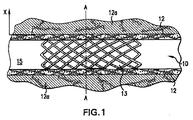
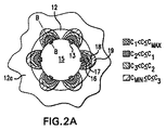
図1において、コーティングステント(コーティングが施されたステント)10が、血管15の中に定位されており、この血管15の血管壁12が処置対象の部位である。この血管壁は、生体組織12aによって囲繞されている。そして、ステント10のストラット13の表面にコーティングされている生体活性物質が、この処置対象の血管壁12の中へ放出されて行く。図2は、図1のステント10のA線に沿った断面図である。図2では更に、ステント10を血管15の中に挿入してからある時間が経過した時点での、ストラット13の周囲の各領域における生体活性物質の濃度レベルを示している。ストラット13に隣接した領域では、即ち、ストラット13と曲線16との間の領域では、濃度レベルがCmaxと同じかそれよりも低く、毒性発現レベルより僅かに低いレベルになっている。処置対象の生体組織の位置がストラット13から離れているほど、その生体組織へデリバリーされる生体活性物質の濃度は低下している。ただし、曲線18と曲線19との間の領域ではまだ、濃度レベルがCminと同じかそれより僅かに高くなっている。そして、曲線19より外側の領域では、生体活性物質の濃度がCmin以下に低下している。
In FIG. 1, a coated stent (coated stent) 10 is localized in a
更に、図2A及び図2Bから明らかなように、ストラット13どうしの間には、濃度がCminに達する十分な量の生体活性物質を、処置対象の血管壁が受け取ることのできない空白領域が存在している。ストラット13にコーティングする生体活性物質の量を増量すれば、それによって、曲線19より内側の領域の大きさを、即ち、濃度がCmin以上の領域の大きさを拡大して、当該領域が、処置対象の血管壁12のうちのより大きな領域を包含するようにすることができる。しかしながら、そうした場合には、ストラット13に隣接した領域における生体活性物質の濃度も上昇するため、そちらの領域における濃度が毒性発現レベルを超えてしまうおそれがある。従って、生体組織の全領域に亘って、生体活性物質の濃度がCmin以上で毒性発現レベル以下となるようにすることができるような、複数のストラットを備えた医用デバイスが求められている。
Further, as is apparent from FIGS. 2A and 2B, there is a blank area between the
ただし、患者の体内に植込まれまたは挿入された医用デバイスに接触した生体組織は、ときとして、有害生理反応を生じる。例えば、ある種のカテーテルやステントを挿入し、または植込んだときには、血管内に塞栓や凝血塊が生成されることがある。また、血管介入処置に対するその他の有害生理反応として、血管内皮細胞ないし血管平滑筋細胞の増殖が発生するということがあり、それらによって更に、動脈における細胞の過形成、動脈の再狭窄ないし再閉塞、血管閉塞、血小板凝集、それに血管の石灰化などが引き起こされることがある。再狭窄の原因は、血管平滑筋細胞に関連したコラーゲン及びプロテオグリカンを含有する細胞外マトリックスが集積することにあり、このような細胞外マトリックスの集積は、アテローム形成部に生じることもあり、また、バルーンによる血管損傷部や血管形成術を施術した後の動脈の過形成部に生じることもある。再狭窄に対する処置としてしばしば行われているのは、血管形成術やバイパス手術を再度施術するということであるが、しかしながら、それらを再度施術することには、再狭窄を反復するリスクなどの様々な不都合が伴うことは明らかである。 However, living tissue that comes into contact with a medical device implanted or inserted into a patient's body sometimes produces adverse physiological reactions. For example, when a certain type of catheter or stent is inserted or implanted, emboli or blood clots can be formed in the blood vessels. In addition, other adverse physiological reactions to vascular intervention procedures include the proliferation of vascular endothelial cells or vascular smooth muscle cells, which further causes cell hyperplasia in the arteries, arterial restenosis or reocclusion, It may cause vascular occlusion, platelet aggregation, and vascular calcification. The cause of restenosis is the accumulation of extracellular matrix containing collagen and proteoglycans associated with vascular smooth muscle cells, such accumulation of extracellular matrix may occur in the atherogenic region, It may also occur in vascular lesions caused by balloons or arterial hyperplasia after angioplasty. A common treatment for restenosis is to re-execute angioplasty or bypass surgery, however, re-applying them requires various risks such as the risk of repeated restenosis. It is clear that there are disadvantages.
生体活性物質を放出する薬剤ステントを使用する処置について考察するときに、考慮しなければならない事項が幾つかある。第1に、薬剤放出ステントを植込む際に、そのステントの病変部カバー領域が、血管造影法によって特定された病変部の領域を、その領域の境界より外側まで十分な余裕をもって包含するようにするためには、そのステントを非常に高い精度をもって定位しなければならない。そのため、ステントを定位するために細心の注意を払ってもなお、病変部の処置に失敗したり、十分な処置を行えなかったりするおそれがある。第2に、生体活性物質をコーティングしたステントが病変部を完全にカバーできた場合であっても、その植込みに際して生じたバルーンによる損傷部が、ステントの両端の外側までに亘っていることもあり得る。そのような損傷部が、血管造影法で視覚化できる場合には、その損傷部をカバーするための更なるステントを植込むことができる。しかしながら、更なるステントを植込む際に、最初のステントを植込んだときと同様にして、更なる損傷部を生じさせてしまうおそれがある。第3に、血管造影法によって、生体組織の損傷部が存在している徴候が発見されなかった場合であっても、ステントの両端の外側に実際に損傷部の領域が存在している可能性がある。 There are several things to consider when considering a procedure using a drug stent that releases a bioactive substance. First, when implanting a drug-releasing stent, the lesion cover area of the stent includes the lesion area identified by angiography with sufficient margin to the outside of the boundary of the area. To do so, the stent must be localized with very high accuracy. For this reason, even if great care is taken to localize the stent, there is a possibility that treatment of the lesioned part may fail or sufficient treatment cannot be performed. Secondly, even when the stent coated with the bioactive substance can completely cover the lesion, the damaged part caused by the balloon during the implantation may extend to the outside of both ends of the stent. obtain. If such a lesion can be visualized by angiography, an additional stent can be implanted to cover the lesion. However, when a further stent is implanted, there is a risk of causing further damage in the same manner as when the first stent was implanted. Third, even if no sign of the presence of a damaged portion of living tissue is found by angiography, there is a possibility that the damaged portion actually exists outside both ends of the stent. There is.
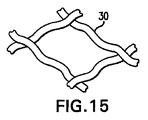
在来の技術に付随するその他の問題として、また特に、放射性ステントに関する問題として、ステントの端部に接触している部分の生体管路の表面に、再狭窄が発生し易いということがある。血管の閉塞及び狭窄は、多くの場合、ステントの端部の近傍において血管細胞が増殖することによって発生する。これは「キャンディ・ラッパー・エフェクト」と呼ばれており、また、エッジ再狭窄、エッジ・エフェクトなどとも呼ばれている。これについて記載した文献としては、Albiero et al., 2000, J. Invas. Cardiol. 12(8):416-421や、Latchem et al., 2000, Catheter Cardiovasc Interv. 51(4):411-429、それに、Kim et al., 2001, J. Am. Coll. Cardiol. 37(4):1026-1030などがある。このエフェクト即ち作用を説明するための模式図を示したのが図25である。図25に示したのはステントが植込まれた生体管路の断面図であり、そのステントの両端の近傍に再狭窄が発生している。即ち、植込まれているステント40の両端の近傍において、生体管路30の表面10が、過形成増殖組織20によって覆われている。その見た目が、あたかも、包み紙で包まれたキャディーのように見えることから、「キャンディー・ラッパー・エフェクト」と呼ばれているのである。ある種の過形成は、生体管路に対する放射線治療を原因として発生することがあり、放射線治療を行うための放射性ステントの放射線源の照準位置は、通常、治療対象の病変部がそこに位置付けられることになる、そのステントの中央に合わせられている。生体管路の健康な生体組織に余分な放射線を照射しないために、放射性ステントの中央をもって、照射照準位置としているのである。そのため、放射性ステントの両端の近傍には、低レベルの放射線が照射されることになるが、そのことが、ステントの端部の近傍における再狭窄の発生原因となることがある。この作用をもたらしている再狭窄の発生機序は、ステントの端部の近傍における線量レベルが、細胞の成長を停止させるのではなく逆に刺激してしまうレベルにあるということである。従って、再狭窄及びそれに関連した病変の防止及び処置のための治療法が、依然として強く求められている。
Another problem associated with conventional techniques, and particularly a problem with radioactive stents, is that restenosis is likely to occur on the surface of the body duct where it contacts the ends of the stent. Vessel occlusion and stenosis are often caused by the proliferation of vascular cells in the vicinity of the end of the stent. This is called a “candy wrapper effect”, and is also called an edge restenosis, an edge effect, or the like. References describing this include Albiero et al., 2000, J. Invas. Cardiol. 12 (8): 416-421 and Latchem et al., 2000, Catheter Cardiovasc Interv. 51 (4): 411-429. And Kim et al., 2001, J. Am. Coll. Cardiol. 37 (4): 1026-1030. FIG. 25 shows a schematic diagram for explaining this effect. FIG. 25 is a cross-sectional view of a biological duct in which a stent is implanted, and restenosis is generated in the vicinity of both ends of the stent. That is, in the vicinity of both ends of the implanted stent 40, the
エッジ・エフェクトは、放射性ステントではないステントでも発生し得る。コーティングが施された従来の医用デバイスでは、一般的に、生体活性物質のコーティング層が、その医用デバイスの全長に亘って、ないしは全表面に亘って、均一に形成されていた。例えば、従来のコーティングステントでは、そのステントの表面の全長に亘って一様にコーティング層が形成されていた。そのコーティング表面の長手方向にとった生体管路における生体活性物質の濃度分布は、ベル形曲線で表される分布となり、即ち、コーティング表面の中央部から放出される生体活性物質によって生じる生体組織内の生体活性物質の濃度はコーティング表面の両端部から放出される生体活性物質によって生じる生体組織内の生体活性物質の濃度よりも高くなる。コーティング表面に沿って、生体組織内に起こる不均一な濃度は、コーティング表面の端にある生体組織において、生体活性物質の不十分であるか、最適状態に及ばない投与量にとどまるかも知れない。そして、生体管路の管路壁における生体活性物質の局所濃度が、医用デバイスのコーティング表面の長手方向においてこのように不均一になることによって、有害作用がもたらされるおそれがある。例えば、生体活性物質のコーティング層が形成されたコーティングステントを、再狭窄の予防または処置のために使用する場合に、そのコーティングステントの両端部の近傍に位置している生体組織へデリバリーされる生体活性物質の量が最適量より少なければ、その部分の生体組織に再狭窄が発生するおそれがある。 Edge effects can also occur with stents that are not radioactive stents. In a conventional medical device with a coating, generally, a coating layer of a bioactive substance is uniformly formed over the entire length of the medical device or over the entire surface. For example, in a conventional coated stent, a coating layer is uniformly formed over the entire length of the surface of the stent. The concentration distribution of the bioactive substance in the biological duct taken along the longitudinal direction of the coating surface becomes a distribution represented by a bell-shaped curve, that is, in the living tissue generated by the bioactive substance released from the center of the coating surface. The concentration of the bioactive substance is higher than the concentration of the bioactive substance in the living tissue caused by the bioactive substance released from both ends of the coating surface. A non-uniform concentration that occurs in the biological tissue along the coating surface may be insufficient or sub-optimal doses of the bioactive substance in the biological tissue at the edge of the coating surface. Then, the local concentration of the bioactive substance in the duct wall of the biomedical duct becomes uneven in the longitudinal direction of the coating surface of the medical device in this way, which may cause harmful effects. For example, when a coated stent on which a coating layer of a bioactive substance is formed is used for the prevention or treatment of restenosis, the living body delivered to a living tissue located near both ends of the coated stent. If the amount of the active substance is less than the optimum amount, restenosis may occur in that part of the living tissue.
医用デバイスのコーティング表面の全長に亘って、コーティングする生体活性物質の量ないし濃度を増大させれば、コーティング表面の両端部の近傍に位置する生体組織へデリバリーされる生体活性物質の投与量を増大させることができる。しかしながら、そうした場合には、コーティング表面の全領域において放出される生体活性物質の濃度ないし量が増大することになるため、それによって、コーティング表面の中央部に位置する生体組織へデリバリーされる生体活性物質の投与量が過大となり、場合によっては毒性発現レベルにまで達してしまうおそれもある。 Increasing the amount or concentration of the bioactive substance to be coated over the entire length of the coating surface of the medical device increases the dose of bioactive substance delivered to the living tissue located near both ends of the coating surface Can be made. However, in such a case, the concentration or amount of the bioactive substance released in the entire area of the coating surface will increase, so that the bioactivity delivered to the biological tissue located in the central part of the coating surface. The dose of the substance becomes excessive, and in some cases, the level of toxicity may be reached.
従って、以下のような医用デバイスが求められており、その医用デバイスとは、病変部に対してその医用デバイスを高精度で定位することができ、その医用デバイスのコーティング表面の全長に亘って生体活性物質の濃度分布をより一様な分布にすることができ、植込んだその医用デバイスの両端部及びその外側に至るまでの生体活性物質の処置濃度を適正な濃度にすることのできる医用デバイスである。本発明によれば、有害なエフェクト即ち作用が発生する可能性を払拭することができ、また特に、血管内膜の過形成及び血管平滑筋細胞の増殖を防止することができ、それらは生体管路の狭窄ないし再狭窄の原因となるものであり、また、それらは不均一な生体活性物質濃度分布によって引き起こされるものである。 Therefore, there is a need for the following medical device, which is capable of localizing the medical device with respect to the lesion with high accuracy, and is capable of living over the entire length of the coating surface of the medical device. The medical device can make the concentration distribution of the active substance more uniform, and can make the treatment concentration of the bioactive substance to both ends and outside of the implanted medical device an appropriate concentration. It is. According to the present invention, it is possible to dispel the possibility that harmful effects occur, and in particular, it is possible to prevent vascular intimal hyperplasia and vascular smooth muscle cell proliferation, It causes stenosis or restenosis of the tract, and they are caused by uneven bioactive substance concentration distribution.
更に、生体組織に臨む外表面の全領域に亘って生体活性物質のコーティング層を均一に形成した医用デバイスは、一般的に、その生体活性物質を、生体組織の特定部位へデリバリーするために用いられる。例えば、そのような医用デバイスは、生体管路内の病変部に処置を施すために用いられる。しかしながら、そのような医用デバイスでは、その外表面の全領域が生体活性物質を含有するため、その生体活性物質は、病変部ばかりでなく健康な生体組織へもデリバリーされてしまう。健康な生体組織に対して、生体活性物質による処置が施されることは、単に不必要であるというだけでなく、場合によっては有害ですらある。従って、以下のような医用デバイスが求められており、その医用デバイスとは、生体活性物質の放出量分布を非対称的な分布とすることができ、それによって、生体組織のうちの生体活性物質を必要としている領域にだけ、生体活性物質をデリバリーできるようにした医用デバイスである。 Furthermore, a medical device in which a coating layer of a bioactive substance is uniformly formed over the entire area of the outer surface facing the living tissue is generally used to deliver the bioactive substance to a specific part of the living tissue. It is done. For example, such a medical device is used to treat a lesion in a biological duct. However, in such a medical device, since the entire area of the outer surface thereof contains a bioactive substance, the bioactive substance is delivered not only to a lesioned part but also to healthy living tissue. Treating healthy biological tissue with a bioactive substance is not only unnecessary, but may be harmful in some cases. Accordingly, there is a need for a medical device such as that described below, and the medical device can have an asymmetric distribution of the amount of released bioactive substance, thereby reducing the bioactive substance in the living tissue. It is a medical device that can deliver a bioactive substance only to a necessary area.
尚、以上の説明においては様々な文献を引用したが、それら文献を引用したことをもって、それら文献が本発明にとっての先行技術に該当するものであることを本出願人が容認したと解釈されてはならない。 In the above description, various documents are cited. However, it is interpreted that the applicant has accepted that these documents fall under the prior art for the present invention. Must not.
以上の目的並びにその他の目的が、本発明によって達成される。以上の目的を達成するために、本出願人らは、患者の生体組織へ生体活性物質をデリバリーするための医用デバイスと、かかるデバイスの設計方法と、生体組織へ生体活性物質をデリバリーする方法とを発明したものである。 The above and other objects are achieved by the present invention. In order to achieve the above object, the present applicants provide a medical device for delivering a bioactive substance to a living tissue of a patient, a method for designing such a device, and a method for delivering a bioactive substance to a living tissue. Was invented.
本発明の医用デバイスは、処置を必要としている患者の生体組織へ生体活性物質をデリバリーするための医用デバイスである。この医用デバイスは、複数のストラットと、それらストラットに一体的に設けられた複数の非構造的エレメントとを備えており、それらストラット及びそれら非構造的エレメントが生体活性物質を備えている。1つの実施の形態においては、非構造的エレメントはストラットから突出しており、円錐形、円錐台形、楕円体形、直線ロッド形、屈曲ロッド形、及び、先端に頭部を有するロッド形から成る部類中から選択された形状を有する。別の実施の形態においては、非構造的エレメントは輪状部形、こぶ状部形、及び、屈曲部形からなる部類中から選択された形状を有し、それらはステントに沿って形成されるものである。更に別の実施の形態においては、この医用デバイスは、外表面を有する筒状部分を備え、前記複数の非構造的エレメントは、前記外表面の全領域に亘って分布するように配置されている。更に別の実施の形態においては、前記複数の非構造的エレメントは、前記外表面に周方向に非対称的な分布を成すように配置されている。この場合、例えば、前記複数の非構造的エレメントが、前記外表面のうちの矩形部分にだけ分布するように配置されているようにし、あるいは、前記矩形部分が、前記筒状部分の長手方向軸に平行に延在しているようにする。また、前記矩形部分と前記筒状部分とが、同じ長さを有するようにしてもよい。また、前記矩形部分の表面積が、前記外表面の全領域の表面積の約25%〜約75%に相当するようにしてもよい。更に別の実施の形態では、前記外表面が端部領域と中央領域とを有しており、前記中央領域よりも前記端部領域の方において、単位長さ外表面あたりの前記非構造的エレメントの個数を多くしている。また、別の実施の形態では、前記生体活性物質を、パクリタクセル、アクチノマイシン、シロリムス、タクロリムス、エベロリムス、デキサメタゾン、ハロフギノン、及び、疎水性酸化窒素アダクトから成る部類中から選択したものとしている。 The medical device of the present invention is a medical device for delivering a bioactive substance to a living tissue of a patient in need of treatment. The medical device includes a plurality of struts and a plurality of non-structural elements provided integrally with the struts, and the struts and the non-structural elements include a bioactive substance. In one embodiment, the non-structural element protrudes from the strut and is in the class of conical, frustoconical, ellipsoidal, linear rod, bent rod, and rod with a head at the tip. Having a shape selected from In another embodiment, the non-structural elements have a shape selected from the class consisting of annulus, hump, and bend, which are formed along the stent. It is. In yet another embodiment, the medical device includes a cylindrical portion having an outer surface, and the plurality of non-structural elements are arranged to be distributed over the entire area of the outer surface. . In still another embodiment, the plurality of non-structural elements are arranged on the outer surface so as to have a circumferentially asymmetric distribution. In this case, for example, the plurality of non-structural elements are arranged so as to be distributed only in a rectangular portion of the outer surface, or the rectangular portion is a longitudinal axis of the cylindrical portion. So that it extends parallel to Further, the rectangular portion and the cylindrical portion may have the same length. In addition, the surface area of the rectangular portion may correspond to about 25% to about 75% of the surface area of the entire area of the outer surface. In yet another embodiment, the outer surface has an end region and a central region, and the non-structural elements per unit length outer surface in the end region rather than the central region. The number of is increased. In another embodiment, the bioactive substance is selected from the group consisting of paclitaxel, actinomycin, sirolimus, tacrolimus, everolimus, dexamethasone, halofuginone, and a hydrophobic nitric oxide adduct.
本発明は更に、以上に述べた医用デバイスを用いて生体組織へ生体活性物質をデリバリーする方法に関するものであり、この方法においては、前記医用デバイスを患者の体内に挿入する。 The present invention further relates to a method of delivering a bioactive substance to a living tissue using the medical device described above. In this method, the medical device is inserted into a patient's body.
本発明は更に、患者の生体組織へ生体活性物質をデリバリーするための医用デバイスを設計する方法に関するものであり、設計する医用デバイスは、例えばステントなどであって、複数のストラットとそれらストラットに一体に設けられた複数の非構造的エレメントとを備え、それらストラット及びそれら非構造的エレメントが生体活性物質を備えた医用デバイスである。この方法においては(a)ある形状パターンで配列された複数のストラットを備えた暫定医用デバイスを用意し、(b)前記暫定医用デバイスから放出される前記生体活性物質の濃度分布を求め、そして、(c)前記暫定医用デバイスの前記複数のストラットの前記形状パターンに対して、前記生体活性物質を備えた複数の非構造的エレメントを前記複数のストラットに一体的に設けて付加するという改変を加え、それによって前記生体組織における前記生体活性物質の分布をより望ましいものにする。1つの実施の形態では、前記生体活性物質が、前記生体組織に対応した最小有効濃度と最大有効濃度とを有しており、前記ステップ(b)及び前記ステップ(c)を反復することによって、処置対象の前記生体組織における前記生体活性物質の濃度が、所望の期間中、前記最小有効濃度以下になることも前記最大有効濃度以上になることもないようにしている。また、別の実施の形態では、前記生体活性物質を、パクリタクセル、アクチノマイシン、シロリムス、タクロリムス、エベロリムス、デキサメタゾン、ハロフギノン、及び、疎水性酸化窒素アダクトから成る部類中から選択するようにしている。 The present invention further relates to a method for designing a medical device for delivering a bioactive substance to a living tissue of a patient, and the designed medical device is, for example, a stent, which is integrated with a plurality of struts. And a plurality of non-structural elements, and the struts and the non-structural elements are medical devices having a bioactive substance. In this method, (a) a provisional medical device having a plurality of struts arranged in a certain shape pattern is prepared, (b) a concentration distribution of the bioactive substance released from the provisional medical device is obtained, and (C) To the shape pattern of the plurality of struts of the provisional medical device, a modification is added in which a plurality of nonstructural elements including the bioactive substance are integrally provided and added to the plurality of struts. , Thereby making the distribution of the bioactive substance in the biological tissue more desirable. In one embodiment, the bioactive substance has a minimum effective concentration and a maximum effective concentration corresponding to the biological tissue, and by repeating the step (b) and the step (c), The concentration of the biologically active substance in the biological tissue to be treated is not lower than the minimum effective concentration or higher than the maximum effective concentration during a desired period. In another embodiment, the bioactive substance is selected from the group consisting of paclitaxel, actinomycin, sirolimus, tacrolimus, everolimus, dexamethasone, halofuginone, and a hydrophobic nitric oxide adduct.
本発明は更に、患者の体内に挿入可能な医用デバイスに関するものであり、この医用デバイスは例えばステントなどである。この医用デバイスは、複数のストラットで画成された外表面を有し、該外表面は中央領域と端部領域とを有している。そして、前記中央領域よりも前記端部領域の方において、単位長さ外表面あたりの利用可能表面積をより大きなものにしている。その1つの実施の形態では、前記中央領域よりも、前記中央領域及び前記端部領域の各々の少なくとも一部の方において、生体活性物質に対する単位長さ外表面あたりの親和力をより大きなものにしている。別の実施の形態では、前記中央領域よりも前記端部領域の方において、単位長さ外表面あたりの生体活性物質の量をより多くしている。更に別の実施の形態では、前記中央領域及び前記端部領域の各々の少なくとも一部が生体活性物質を含有するコーティング層で被覆されており、更に、前記中央領域においては、該中央領域を被覆している前記コーティング層の上にバリア層が形成されている。別の実施の形態では、前記端部領域を、前記中央領域の位置しているストラットと比べてより多孔度の高い表面とすることによって、前記端部領域がより大きな表面積を持つようにしている。前記端部領域にあるストラットは多孔質材料で形成され、前記中央領域にあるストラットは多孔度の低い材料で形成されている。前記端部領域にあるストラットは多孔質材料で被覆されており、前記中央領域にあるストラットは多孔度の低い材料で被覆されている。前記端部領域にあるストラットの平均線径は、前記中央領域にあるストラットの平均線径より小さい。 The present invention further relates to a medical device that can be inserted into a patient's body, such as a stent. The medical device has an outer surface defined by a plurality of struts, the outer surface having a central region and an end region. And the usable surface area per unit length outer surface is made larger in the end region than in the central region. In one embodiment thereof, the affinity per unit length outer surface with respect to the bioactive substance is made larger in at least a part of each of the central region and the end region than the central region. Yes. In another embodiment, the amount of the bioactive substance per unit length outer surface is larger in the end region than in the central region. In still another embodiment, at least a part of each of the central region and the end region is covered with a coating layer containing a bioactive substance, and the central region is covered with the central region. A barrier layer is formed on the coating layer. In another embodiment, the end region has a higher surface area by making the end region a more porous surface than the strut in which the central region is located. . The struts in the end region are formed of a porous material, and the struts in the central region are formed of a low porosity material. The struts in the end region are coated with a porous material, and the struts in the central region are coated with a low porosity material. The average wire diameter of the struts in the end region is smaller than the average wire diameter of the struts in the central region.
また、本発明は、生体組織に処置を施すための医用デバイスの更に別の実施の形態を提供する。この実施の形態の医用デバイスは、複数のストラットで画成された外表面を備えている。前記外表面は、該外表面の矩形部分が、該外表面のその他の部分と比べて、より大きな単位長さ外表面あたりの生体活性物質の実装容量ないし含有容量を有するようにしている。また、別の実施の形態では、前記矩形部分が、前記生体活性物質に対するより大きな親和力を有するようにしている。本発明は更に、生体活性物質をデリバリーバリする方法に関するものであり、この方法においては、処置を必要とする生体組織に前記矩形部分が直接接触するようにして、以上に述べた生体活性物質を備えた医用デバイスを挿入するようにしている。 The present invention also provides another embodiment of a medical device for performing treatment on living tissue. The medical device of this embodiment includes an outer surface defined by a plurality of struts. In the outer surface, the rectangular portion of the outer surface has a larger mounting capacity or content capacity of the bioactive substance per unit length outer surface than the other portions of the outer surface. In another embodiment, the rectangular portion has a greater affinity for the bioactive substance. The present invention further relates to a method for delivering a bioactive substance. In this method, the above-mentioned bioactive substance is used so that the rectangular portion is in direct contact with a biological tissue requiring treatment. The provided medical device is inserted.
別の実施の形態では、前記中央領域よりも前記端部領域の方において、前記生体活性物質に対する単位長さ外表面あたりの親和力を大きなものにしている。前記外表面の前記中央領域及び前記端部領域の各々の少なくとも一部が、生体活性物質を備えるようにしている。前記端部領域に位置するスラットは第1の母材料を備えたものとし、前記中央領域に位置するスラットは第2の母材料を備えたものとしている。前記第1の母材料は前記第2の母材料と比べて、前記生体活性物質に対する親和力がより大きなものである。前記端部領域にあるストラットは第1の母材料のコーティング層で被覆され、前記中央領域にあるストラットは第2の母材料のコーティング層で被覆されている。前記端部領域及び前記中央領域は更に前記生体活性物質を備えている。 In another embodiment, the affinity per unit length outer surface for the bioactive substance is greater in the end region than in the central region. At least a part of each of the central region and the end region of the outer surface is provided with a bioactive substance. The slats located in the end region are provided with a first base material, and the slats located in the central region are provided with a second base material. The first base material has a greater affinity for the bioactive substance than the second base material. The struts in the end region are covered with a coating layer of a first base material, and the struts in the central region are covered with a coating layer of a second base material. The end region and the central region further comprise the bioactive substance.
前記中央領域及び前記端部領域の各々の少なくとも一部を、結合材料で被覆するようにしており、前記中央領域にあるストラットよりも前記端部領域にあるストラットの方において、単位長さ外表面あたりの前記結合材料の量をより多くしている。前記外表面は前記生体活性物質を備え、該生体活性物質は前記結合材料に結合している。 At least a part of each of the central region and the end region is covered with a binding material, and the outer surface of the unit length in the strut in the end region rather than the strut in the central region. The amount of the above-mentioned bonding material is increased. The outer surface includes the bioactive substance, and the bioactive substance is bonded to the binding material.
更に別の実施の形態においては、前記中央領域よりも前記端部領域の方において、単位長さ外表面あたりの前記生体活性物質の量をより多くしている。本発明は更に、患者の体内に挿入可能な医用デバイスに関するものであり、この医用デバイスは外表面を備え、該外表面は中央領域と端部領域とを有し、前記中央領域及び前記端部領域の各々の少なくとも一部が第1の生体活性物質を含有するコーティング層で被覆されており、前記中央領域よりも前記端部領域の方において、単位長さ外表面あたりの前記第1の生体活性物質の含有量をより多くしている。この医用デバイスは、前記外表面を画成している筒状部分を備えている。前記端部領域を被覆しているコーティングは、第2の生体活性物質を含有するコーティング層を更に含むものとしてもよい。 In still another embodiment, the amount of the bioactive substance per unit length outer surface is increased in the end region than in the central region. The present invention further relates to a medical device insertable into a patient's body, the medical device comprising an outer surface, the outer surface having a central region and an end region, wherein the central region and the end portion At least a part of each region is covered with a coating layer containing a first bioactive substance, and the first living body per unit length outer surface in the end region rather than the central region. The active substance content is increased. The medical device includes a cylindrical portion that defines the outer surface. The coating covering the end region may further include a coating layer containing a second bioactive substance.
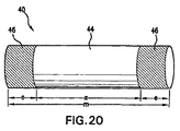
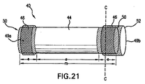
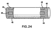
また別の実施の形態として、本発明は、周壁部と第1のバンドとを備えた医用デバイスを提供するものであり、前記バンドは、第1の生体活性物質を備えている。この医用デバイスの前記周壁部は、中央領域と、第1の端部領域と、第2の端部領域とを有する。前記第1のバンドは前記第1の端部領域に取付けられている。別の実施の形態では、第2のバンドが前記第2の端部領域に取付けられている。 As another embodiment, the present invention provides a medical device including a peripheral wall portion and a first band, and the band includes a first bioactive substance. The peripheral wall portion of the medical device has a central region, a first end region, and a second end region. The first band is attached to the first end region. In another embodiment, a second band is attached to the second end region.
また、別の実施の形態として、本発明は、中央領域と、第1及び第2の端部領域とを備えた医用デバイスを提供するものである。前記第1及び第2の端部領域の各々が端縁を有しており、前記第1のバンドが内端を有しており、前記第1のバンドの前記内端が前記第1の端部領域の前記端縁に近接するようにして、前記第1のバンドが前記第1の端部領域に取付けられている。 As another embodiment, the present invention provides a medical device having a central region and first and second end regions. Each of the first and second end regions has an edge, the first band has an inner end, and the inner end of the first band is the first end. The first band is attached to the first end region so as to be close to the edge of the partial region.
第5.1章 生体活性物質を望ましい分布をもってデリバリーする医用デバイス
第5.1.1章 非構造的エレメントについて
薬理作用を有する生体活性物質を生体組織へデリバリーしても、デリバリー先の生体組織におけるその生体活性物質の濃度がある濃度に達しなければ、その薬理作用は発現しない。この濃度を、その生体組織に対応したその生体活性物質の最小有効濃度(Cmin)という。Cminの値は生体活性物質ごとに異なる。更に、生体活性物質が同一であってもデリバリー先の生体組織が異なれば、やはりCminの値は異なる。また一方で、生体活性物質は、ある濃度以上では毒性を発現する。この濃度を、最大有効濃度(Cmax)という。更に、処置対象の生体組織へデリバリーされた生体活性物質の、そのデリバリー先の生体組織の全領域における平均濃度が、Cmin以上でCmax以下であるというだけではなお不十分である。即ち、処置対象のその生体組織の全領域中のどの部分においても、その生体活性物質の濃度が、その生体活性物質のCmin以上でCmax以下であるようにすることが望まれる。
Even when the bioactive substance having a pharmacological action on the medical device 5.1.1 Section nonstructural elements to deliver with the desired distribution of the chapter 5.1 bioactive substance delivery to the body tissue, the delivery destination of the biological tissue If the concentration of the bioactive substance does not reach a certain level, the pharmacological action does not appear. This concentration is called the minimum effective concentration ( Cmin ) of the bioactive substance corresponding to the living tissue. The value of C min varies from bioactive substances. Further, different bioactive materials can be delivered destination of the living tissue of the same, also the value of C min are different. On the other hand, the bioactive substance exhibits toxicity at a certain concentration or higher. This concentration is referred to as the maximum effective concentration (C max ). Furthermore, it is still insufficient that the average concentration of the bioactive substance delivered to the treatment target biological tissue in the entire region of the delivery target biological tissue is C min or more and C max or less. In other words, it is desired that the concentration of the bioactive substance in any part of the whole region of the biological tissue to be treated is C min or more and C max or less of the bioactive substance.
医用デバイスが複数のストラットを備えており、それら複数のストラットが生体活性物質を備えている場合に、生体組織におけるその生体活性物質の濃度は、その医用デバイスの各「セル」(即ち、ストラットに囲まれた個々の開口部)の中心またはその近傍に位置している生体組織において最も低くなる傾向があり、その濃度はCmin以下になることもある。生体活性物質が疎水性のものである場合には特にそうなりやすい。各セルの中心に位置している生体組織における生体活性物質の濃度がCmin以下である場合に、各ストラットの外表面にコーティングする生体活性物質の量を増やすならば、それによって、その濃度を上昇させることができる。しかしながら、そうした場合には、ストラットに隣接して位置している生体組織における濃度が、Cmaxを超えてしまうおそれがある。 If the medical device comprises a plurality of struts and the plurality of struts comprise a bioactive substance, the concentration of the bioactive substance in the biological tissue is determined by each “cell” (ie, strut of the medical device). It tends to be lowest in the living tissue located at the center of the enclosed individual openings) or in the vicinity thereof, and the concentration may be C min or less. This is particularly likely when the bioactive substance is hydrophobic. If the bioactive substance concentration in the biological tissue located at the center of each cell is C min or less, if the amount of bioactive substance coated on the outer surface of each strut is increased, the concentration is thereby reduced. Can be raised. However, in such a case, the concentration in the biological tissue located adjacent to the strut may exceed C max .
その具体例として、例えば、図1に示したコーティングステント(コーティングが施されたステント)10は、従来の形状パターンを有するステントである。同図において、ステント10は血管15の中に定位されており、この血管15の血管壁12が処置対象の部位である。このステント10のストラット13の表面にコーティングされている生体活性物質が、この処置対象の血管壁12の中へ放出されて行く。図2A及び図2Bは、図1のステント10の断面図を示すと共に、このステント10を血管15の中に挿入してからある時間が経過した時点での、ストラット13の周囲の各領域における生体活性物質の濃度レベルを示しており、図2Aに示したのはA−A線に沿った断面図、図2Bに示したのはB−B線(図2A参照)に沿った断面図である。ストラット13に隣接した領域では、即ち、ストラット13と曲線16との間の領域では、濃度レベルがCmaxと同じかそれよりも低く、毒性発現レベルより僅かに低いレベルになっている。領域の位置がストラット13から離れているほど、濃度は低下している。即ち、曲線16と曲線17との間の領域から、曲線17と曲線18との間の領域へ、そして更に曲線18と曲線19の領域へと移行するにつれて、次第に濃度レベルは低下している。そして、曲線18と曲線19との間の領域では、濃度レベルがCminと同じかそれより僅かに高くなっている。曲線19より外側の領域では、生体活性物質の濃度がCminより低く、従ってこの領域では生体活性物質の薬理作用は発現しない。
As a specific example thereof, for example, a coated stent (coated stent) 10 shown in FIG. 1 is a stent having a conventional shape pattern. In the figure, the
更に、図2A及び図2Bから明らかなように、ストラット13どうしの間、即ち、個々のセルの中心近傍には、濃度がCminに達する十分な量の生体活性物質を、処置対象の血管壁が受け取ることのできない空白領域が存在している。ストラット13にコーティングする生体活性物質の量を増量すれば、それによって、曲線19より内側の領域の大きさを、即ち、濃度がCmin以上の領域の大きさを拡大して、当該領域が、処置対象の血管壁12の全領域を包含するようにすることができる。しかしながら、そうした場合には、ストラット13に隣接した領域における生体活性物質の濃度も上昇するため、そちらの領域における濃度が毒性発現レベルを超えてしまうおそれがある。従って、処置対象の生体組織の全領域に亘って、生体活性物質の濃度が確実にCmin以上でCmax以下となるようにすることができるような、医用デバイスが求められている。
Further, as is apparent from FIGS. 2A and 2B, a sufficient amount of bioactive substance having a concentration reaching C min is introduced between the
このように処置対象の生体組織の全領域に亘って、生体活性物質の濃度分布が望ましいものとなるようにするために、本発明の医用デバイスの様々な実施の形態は、複数のストラットと、それらストラットに一体的に複数の非構造的エレメントとを備えたものとしている。ストラット及び非構造的エレメントは生体活性物質を備えている。非構造的エレメントを利用して、生体組織における生体活性物質の濃度分布を調節するようにしており、即ち、医用デバイスから放出されて生体組織の中へ出て行く生体活性物質の濃度分布が、望ましいものとなるようにしている。より具体的には、例えば、本発明の医用デバイスによれば、ストラットに隣接している領域の生体組織における局所的濃度をCmax以上に上昇させることなく、セルの中心に位置している生体組織における濃度をCmin以上にすることができる。 Thus, in order for the concentration distribution of the bioactive substance to be desirable over the entire region of the biological tissue to be treated, various embodiments of the medical device of the present invention include a plurality of struts, These struts are integrally provided with a plurality of non-structural elements. The struts and non-structural elements are equipped with bioactive substances. The non-structural element is used to adjust the concentration distribution of the bioactive substance in the living tissue, that is, the concentration distribution of the bioactive substance released from the medical device and exiting into the living tissue is To be desirable. More specifically, for example, according to the medical device of the present invention, the living body positioned at the center of the cell without increasing the local concentration in the living tissue in the region adjacent to the strut to C max or higher. The concentration in the tissue can be C min or higher.
その具体例を図3、図4A、及び図4Bに示した。図3に示したコーティングステント10’は、図1に示したコーティングステント10の従来の形状パターンに対して、その複数のストラット13に複数の非構造的エレメント14を付加するという改変を加えて得られたものであり、付加された非構造的エレメント14はストラット13に一体的に設けられている。同図において、ステント10’は血管15の中に定位されており、この血管15の血管壁12が処置対象の部位である。このステント10’のストラット13及び非構造的エレメント14の表面にコーティングされている生体活性物質が、処置対象の血管壁12の中へ、並びに、この血管壁12の周囲の生体組織12aの中へ放出されて行く。図4A及び図4Bは、図3のステント10’の断面図を示すと共に、このステント10’を血管15の中に挿入してからある時間が経過した時点での、ストラット13及び非構造的エレメント14の周囲の各領域における生体活性物質の濃度レベルを示しており、図4Aに示したのはC−C線に沿った断面図、図4Bに示したのはD−D線(図4A参照)に沿った断面図である。ストラット13に隣接した領域では、即ち、ストラット13ないし非構造的エレメント14と曲線16との間の領域では、濃度レベルがCmaxと同じかそれよりも低く、毒性発現レベルより僅かに低いだけの濃度となっている。領域がストラット13ないし非構造的エレメント14から離れるほど濃度は低下している。そして、曲線18と曲線19との間の領域では、濃度レベルがCminと同じかそれよりも高い程度となっている。図4から明らかなように、このステント10’によれば、セルの中心に位置している領域までも含めて、処置対象の血管壁12の全領域に亘って濃度をCmin以上にすることができ、しかも、ストラットに隣接する領域の濃度をCmax以上に増大させることなくこれを達成することができる。
Specific examples thereof are shown in FIGS. 3, 4A, and 4B. The
ここでいう「非構造的エレメント」とは、ストラットに一体的に設けられたエレメントであって、ストラットから突出した形態のエレメントとして設けることもでき、或いは、ストラットに沿って延在する形態のエレメントとして設けることもできるものである。また、かかる非構造的エレメントは、ストラットの機械的特性に対しては、実質的な影響を及ぼすことのないものであり、例えば、複数のストラットを備えた構成の医用デバイスについていえば、その医用デバイスの(1)径方向強度、(2)長手方向伸縮性、(3)拡張比、(4)圧縮性、及び(5)全体形状、等々の特性には影響を及ぼさない。本発明の医用デバイスの様々な実施の形態では、このような非構造的エレメントを、ストラットに一体的に設けるようにしており、即ち、通常は、非構造的エレメントの形成材料はストラットの形成材料と同一材料であり、非構造的エレメントはストラットの連続した一部分として形成される。また、非構造的エレメントは、ストラットを形成する際に同時に形成することが好ましく、そうするには、例えば、金属材料やポリマー材料の板材から、レーザーアブレーション法を用いて、非構造的エレメントを備えたストラットを製作するなどの方法を用いるとよい。 The term “non-structural element” as used herein refers to an element that is provided integrally with the strut, and can be provided as an element that protrudes from the strut, or an element that extends along the strut. It can also be provided as. Such non-structural elements have no substantial effect on the mechanical properties of the struts. For example, in the case of a medical device having a plurality of struts, the medical device It does not affect the device's (1) radial strength, (2) longitudinal stretchability, (3) expansion ratio, (4) compressibility, and (5) overall shape. In various embodiments of the medical device of the present invention, such a non-structural element is provided integrally with the strut, that is, the non-structural element forming material is usually the strut forming material. The non-structural elements are formed as a continuous part of the strut. The non-structural element is preferably formed at the same time as the strut is formed. For this purpose, the non-structural element is provided by using a laser ablation method from a metal material or a polymer material plate, for example. It is recommended to use a method such as manufacturing a strut.
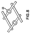
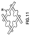
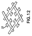
図5に示したのは、非構造的エレメントを備えていない従来のストラットの具体例であり、図6〜図14に示したのは、この従来のストラットに一体的に設けた様々な非構造的エレメントの具体例である。非構造的エレメントの形状は様々なものとすることができ、ここに具体的に示したものに限定されない。具体例として図示した非構造的エレメントの形状には、直線ロッド形(図6の21)、円錐形(図7の22)、円錐台形(不図示)、輪状部形(図8の23)、こぶ状部形(図9の24)、屈曲ロッド形(図10の25)、楕円体形(図11の26)、それに、先端に頭部を有するロッド形(図12の27及び図13の28)がある。更に、ストラットそれ自体の屈曲部(図14の29a及び29b)も、それがストラットの機械的特性に影響を及ぼさない限りにおいて、非構造的エレメントとして用いることができる。 FIG. 5 shows a specific example of a conventional strut having no non-structural elements. FIGS. 6 to 14 show various non-structures provided integrally with the conventional strut. This is a specific example of a dynamic element. The shape of the non-structural element can vary and is not limited to what is specifically shown here. Non-structural elements illustrated as specific examples include straight rod shapes (21 in FIG. 6), cone shapes (22 in FIG. 7), truncated cone shapes (not shown), ring-shaped portions (23 in FIG. 8), Hump-shaped portion (24 in FIG. 9), bent rod shape (25 in FIG. 10), ellipsoidal shape (26 in FIG. 11), and rod shape having a head at the tip (27 in FIG. 12 and 28 in FIG. 13). ) Furthermore, the bends of the struts themselves (29a and 29b in FIG. 14) can also be used as non-structural elements as long as they do not affect the mechanical properties of the struts.
本発明の実施の形態にかかる医用デバイスは、任意の種類の生体活性物質をデリバリーするという目的に使用することができる。デリバリーする生体活性物質は、疎水性のものであることが好ましく、その具体例を挙げるならば、例えば、パクリタクセル、アクチノマイシン、シロリムス、タクロリムス、エベロリムス、デキサメタゾン、ハロフギノン、それに、様々な疎水性酸化窒素アダクトなどがある。デリバリーすることのできる生体活性物質のその他の具体例と、生体活性物質を含有するコーティング層の具体例と、医用デバイスの具体例とについて、本明細書中において後ほど説明する。 The medical device according to the embodiment of the present invention can be used for the purpose of delivering any kind of bioactive substance. The bioactive substance to be delivered is preferably a hydrophobic substance. Specific examples thereof include, for example, paclitaxel, actinomycin, sirolimus, tacrolimus, everolimus, dexamethasone, halofuginone, and various hydrophobic nitric oxides. There are adducts. Other specific examples of bioactive substances that can be delivered, specific examples of coating layers containing bioactive substances, and specific examples of medical devices will be described later in this specification.
第5.1.2章 複数のストラットと複数の非構造的エレメントとを備えた医用デバイスを設計する方法
本発明は、患者の生体組織へ生体活性物質をデリバリーするための、複数のストラットとそれらストラットに一体的に設けた複数の非構造的エレメントとを備えた医用デバイスを設計する方法に関する。既述のごとく、複数のストラットがある形状パターンで配列されているときに、その形状パターンの各セルの中心における生体活性物質の濃度が、その生体活性物質のCminに達しないことがある。しかるに、本発明の設計方法によれば、ストラットに隣接している生体組織における生体活性物質の濃度をCmax以上に上昇させることなく、処置対象の生体組織の全領域に亘って生体活性物質の濃度をCmin以上にすることができる、ストラットの形状パターンが提供される。
5.1.2 Method for designing a medical device comprising a plurality of struts and a plurality of non-structural elements The present invention relates to a plurality of struts for delivering a bioactive substance to a patient's biological tissue The present invention relates to a method for designing a medical device comprising a plurality of non-structural elements integrally provided on a strut. As described above, when a plurality of struts are arranged in a certain shape pattern, the concentration of the bioactive substance at the center of each cell of the shape pattern may not reach C min of the bioactive substance. However, according to the design method of the present invention, the concentration of the bioactive substance in the living tissue adjacent to the strut is increased over the entire region of the living tissue to be treated without increasing the concentration of the bioactive substance to C max or higher. A strut shape pattern is provided in which the concentration can be C min or higher.
本発明の方法においては、ある形状パターンで配列されている複数のストラットを備えている暫定医用デバイスに対して、それら複数のストラットに複数の非構造的エレメントを一体的に設けるという改変を加えることによって、その医用デバイスから処置対象の生体組織の中へ放出される生体活性物質の濃度分布を改善する。複数のストラットがある形状パターンで配列されている医用デバイスとは、例えばステントなどであるが、ただし、ステントのみに限定されず、そのように配列されている複数のストラットが生体活性物質を備えているものであるならば、任意の種類の医用デバイスが本発明の方法における暫定医用デバイスとして用いられる。 In the method of the present invention, the provisional medical device including a plurality of struts arranged in a certain shape pattern is modified such that a plurality of nonstructural elements are integrally provided on the plurality of struts. Improves the concentration distribution of the bioactive substance released from the medical device into the biological tissue to be treated. A medical device in which a plurality of struts are arranged in a shape pattern is, for example, a stent, but is not limited to a stent, and a plurality of struts arranged in such a manner include a bioactive substance. Any type of medical device can be used as a temporary medical device in the method of the present invention.
本発明の方法においては、先ず、暫定医用デバイスから生体組織へデリバリーされる生体活性物質の濃度分布を求める。こうして求めた濃度分布に基づいて、生体活性物質の濃度がCmin以下になるような生体組織の領域を求めることができる。続いて、そのような領域を、前記暫定医用デバイスの前記複数のストラットの前記形状パターンのうちの、そのような領域に接触しまたは近接している部分に関連付ける。 In the method of the present invention, first, a concentration distribution of a bioactive substance delivered from a provisional medical device to a living tissue is obtained. Based on the concentration distribution thus obtained, a region of the biological tissue where the concentration of the bioactive substance is C min or less can be obtained. Subsequently, such regions are associated with portions of the shape pattern of the plurality of struts of the provisional medical device that are in contact with or close to such regions.
濃度分布を求めるには、例えば、処置対象の生体組織と特性が類似した生体組織モデルを用いて、試験管内で生体活性物質を適用してその濃度を実測するなどすればよい。生体組織モデルとしては、例えば、カニューレ状の動物の動脈及びその周囲組織や、人工生体組織などを用いることができる。或いはまた、動物モデルを用いて、生体内で生体活性物質を適用してその濃度を実測するようにしてもよい。動物モデルとしては、例えば、ラビット、モルモット、ブタなどを用いることができる。実験に使用する生体活性物質に、蛍光物質、放射性物質、或いは染料などで、ラベル付けをしておくようにしてもよく、或いはまた、生体組織を蒸解した上でHPLC法によって分析を行うようにしてもよい。生体活性物質にラベル付けする方法を採用する場合には、そのラベル付けした生体活性物質を医用デバイスにコーティングし、そして、そのコーティングを施した医用デバイスを、生体組織モデルまたは人工生体組織の中に挿入し、或いは、動物の体内に植込むようにする。一方、例えばHPLC分離法や質量分光法などをはじめとする、直接的な分析法を用いて生体活性物質を検出するようにすることもできる。医用デバイスを挿入して時間が経過した後に、生体組織を切開して切片を作成し、生体活性物質の濃度を測定することによって、濃度分布を求めることができる。生体活性物質の濃度を測定する方法は、その実験に使用しているラベルに応じた適当な方法で行えばよい。尚、ラベル付けする方法を採用する場合には、そのラベルが生体活性物質の拡散に大きな影響を及ぼさないように注意を払う必要がある。 In order to obtain the concentration distribution, for example, a biological tissue model having characteristics similar to those of the biological tissue to be treated may be used, and the concentration may be measured by applying a bioactive substance in a test tube. As the biological tissue model, for example, a cannulated animal artery and surrounding tissue, an artificial biological tissue, or the like can be used. Alternatively, the concentration may be measured by applying a bioactive substance in vivo using an animal model. Examples of animal models that can be used include rabbits, guinea pigs, and pigs. The bioactive substance used in the experiment may be labeled with a fluorescent substance, radioactive substance, dye, etc., or the biological tissue is digested and analyzed by the HPLC method. May be. When a method for labeling a bioactive substance is adopted, the labeled bioactive substance is coated on a medical device, and the coated medical device is placed in a biological tissue model or artificial biological tissue. Insert or implant into the animal's body. On the other hand, the bioactive substance can be detected by using a direct analysis method such as HPLC separation method or mass spectrometry. After the medical device is inserted and time elapses, the biological tissue is cut open to create a section, and the concentration of the bioactive substance can be measured to obtain the concentration distribution. The method for measuring the concentration of the bioactive substance may be performed by an appropriate method according to the label used in the experiment. When employing a labeling method, care must be taken so that the label does not significantly affect the diffusion of the bioactive substance.
一方、数学的シミュレーションによって濃度分布を求めることも可能である。そのようなシミュレーションは、例えば、以下に示す条件並びに数式に従って行うことができる。 On the other hand, it is also possible to obtain the concentration distribution by mathematical simulation. Such a simulation can be performed, for example, according to the following conditions and mathematical expressions.

上式において、Cは生体組織における生体活性物質の濃度であり、xは医用デバイスと生体組織との境界面に対して垂直なx軸の方向にとった医用デバイスからの距離であり、zはその境界面に対して平行なz軸の方向にとった医用デバイスからの距離であり、Dxは生体活性物質のx軸方向の拡散係数であり、Dzは生体活性物質のz軸方向の拡散係数である。尚、ここでいうx軸及びz軸については、その具体例を、図1、図2B、図3、及び図4Bに示した。Dx及びDzは、ラベル付けした生体活性物質を用いて、上で説明したような試験管内または生体内の実験を行うことによって求めることができる。t=0においてC=0であり、また、その他の境界条件としては以下に示すものがある。 Where C is the concentration of the bioactive substance in the biological tissue, x is the distance from the medical device in the direction of the x axis perpendicular to the interface between the medical device and the biological tissue, and z is The distance from the medical device in the z-axis direction parallel to the boundary surface, Dx is the diffusion coefficient of the bioactive substance in the x-axis direction, and Dz is the diffusion coefficient of the bioactive substance in the z-axis direction It is. Specific examples of the x-axis and z-axis here are shown in FIGS. 1, 2B, 3, and 4B. Dx and Dz can be determined by performing in-vitro or in-vivo experiments as described above using labeled bioactive substances. At t = 0, C = 0, and other boundary conditions include the following.
(i)ストラットと生体組織との境界面(x=0)における共通境界条件として、下記の条件式で表される境界条件が存在する。 (I) As a common boundary condition at the boundary surface (x = 0) between the strut and the living tissue, there is a boundary condition represented by the following conditional expression.
上式において、Crはストラットにおける生体活性物質の濃度であり、h1は物質移動係数である。h1の値は、上で説明したような実験を行って求めることもでき、或いは、当業者には周知の情報に基づいて推定により求めることもできる。 In the above equation, Cr is the concentration of the bioactive substance in the strut, and h 1 is the mass transfer coefficient. The value of h 1 can be obtained by conducting an experiment as described above, or can be obtained by estimation based on information well known to those skilled in the art.
(ii)血流と生体組織との境界面(x=0)における境界条件として、下記の条件式で表される境界条件が存在する。 (Ii) As a boundary condition on the boundary surface (x = 0) between the blood flow and the living tissue, there is a boundary condition represented by the following conditional expression.
上式において、h2はh1とは別のもう1つの物質移動係数である。h2の値は、上で説明したような実験を行って求めることもでき、或いは、当業者には周知の情報に基づいて推定により求めることもできる。 In the above formula, h 2 is another mass transfer coefficient different from h 1 . The value of h 2 can be obtained by performing an experiment as described above, or can be obtained by estimation based on information well known to those skilled in the art.
(iii)血管壁の外膜側の壁面(x=L)における境界条件として、下記の条件式で表される境界条件が存在する。 (Iii) There is a boundary condition represented by the following conditional expression as a boundary condition on the outer wall side wall (x = L) of the blood vessel wall.
上式において、h3は更に別のもう1つの物質移動係数であり、Lは対象領域の幅寸法である。h3の値は、上で説明したような実験を行って求めることもでき、或いは、当業者には周知の情報に基づいて推定により求めることもできる。 In the above equation, h 3 is yet another mass transfer coefficient, and L is the width dimension of the target region. The value of h 3 can be obtained by performing an experiment as described above, or can be obtained by estimation based on information well known to those skilled in the art.
(iv)z軸に対して垂直な断面における「対称性」に基づいた(ゼロ・フラックス)境界条件として、下記の条件式で表される境界条件が存在する。 (Iv) As a (zero flux) boundary condition based on “symmetry” in a cross section perpendicular to the z-axis, there is a boundary condition represented by the following conditional expression.
以上に1つの具体例として説明した方法は、生体活性物質の拡散係数として、生体組織へ浸透して行く方向である深さ方向と、そこから周囲へ拡散して行く方向である拡散距離方向との、2つの方向における2つの拡散係数を用いた簡明なモデルに基づいた方法であるが、本発明の方法は、更に複雑なモデルに基づいた方法とすることも可能である。より複雑なモデルとは、以上に言及した変数の他に更にその他の変数も考慮に入れたモデルであり、考慮に入れられる可能性のある変数としては、例えば、対流の影響を表す変数、血管壁の不均質を反映した変数、細胞の種類に応じた変数、病変部に応じた変数、コーティング層の成分や多孔度に応じた変数、また更に、血流量、体温、血圧、及び/または、インプラントから血管壁に作用する接触圧に応じた変数などがある。 The method described above as one specific example includes a depth direction which is a direction of penetrating into living tissue and a diffusion distance direction which is a direction of diffusing from there to the surroundings as a diffusion coefficient of the bioactive substance. Although the method is based on a simple model using two diffusion coefficients in two directions, the method of the present invention can also be a method based on a more complicated model. A more complex model is a model that takes into account other variables in addition to the variables mentioned above. Examples of variables that may be taken into account include variables representing the effects of convection and blood vessels. Variable reflecting wall heterogeneity, variable according to cell type, variable according to lesion, variable according to coating layer composition and porosity, and also blood flow, body temperature, blood pressure, and / or There are variables depending on the contact pressure acting on the blood vessel wall from the implant.
暫定医用デバイスから放出される生体活性物質の濃度分布が得られたならば、その暫定医用デバイスの形状パターンに対して、複数の非機能的エレメントをその暫定医用デバイスのストラットに一体的に設けて付加するという改変を加え、それによって、処置対象の生体組織における生体活性物質の濃度分布をより望ましいものにする。この場合、付加した非構造的エレメントも、ストラットと同様に、生体活性物質を備えたものとされる。より具体的には、例えば、先に求めた濃度分布に基づいて、生体活性物質の濃度がCmin以下であるような生体組織の領域を求める。続いて、暫定医用デバイスのストラットの形状パターンのどの部分がそのような領域に隣接し、または近接しているかを判定する。そして、形状パターンのそのような部分の近傍に、非構造的エレメントを付加すれば、その非構造的エレメントから放出される生体活性物質によって、生体活性物質の濃度がCmin以下であった生体組織の領域において、その濃度を変化させることができる。 Once the concentration distribution of the bioactive substance released from the provisional medical device is obtained, a plurality of non-functional elements are integrally provided on the strut of the provisional medical device with respect to the shape pattern of the provisional medical device. The modification is added to thereby make the concentration distribution of the bioactive substance in the living tissue to be treated more desirable. In this case, the added nonstructural element is also provided with a bioactive substance, like the strut. More specifically, for example, based on the previously obtained concentration distribution, a region of the biological tissue where the concentration of the bioactive substance is C min or less is obtained. Subsequently, it is determined which part of the shape pattern of the strut of the provisional medical device is adjacent to or close to such a region. If a non-structural element is added in the vicinity of such a portion of the shape pattern, the bioactive substance released from the non-structural element causes the bioactive substance concentration to be C min or less. In the region, the concentration can be changed.
暫定医用デバイスとして、例えば、図1に示したような従来の形状パターンの複数のストラット13を備えたステント10があるものとする。複数のストラット13には生体活性物質がコーティングされている。この場合、先ず、それらストラット13から放出される生体活性物質の生体組織における濃度分布を求める。この濃度分布の具体例を、図2A及び図2Bに、血管15内のステント10の断面図と共に示してある。この濃度分布は、濃度を実測して求めることもでき、また、上で説明したように数学的シミュレーションによって求めることもできる。続いて、その求めた濃度分布に基づいて、暫定ステント10のストラット13の形状パターンに対して、複数の非構造的エレメント14を付加するという改変を加え、そのような改変を加えた形状パターンは、例えば、図3に示したようなものとなる。また、その改変によって、血管壁12における生体活性物質の濃度分布は、図4A及び図4Bに示したような濃度分布になる。図2A及び図2Bの濃度分布と図4A及び図4Bの濃度分布とを比較すれば分かるように、図4A及び図4Bでは、処置対象の血管壁12の全領域に亘って濃度分布がCminより高くCmaxより低くなっている。即ち、改変を加えたステント10’では、暫定ステント10と比べて、処置対象の血管壁12における生体活性物質の濃度分布が、より望ましい分布となっている。
As an interim medical device, for example, there is a
そして、このように改変を加えた医用デバイスから放出される生体活性物質の生体組織における濃度分布を求め、その結果、生体活性物質の局所的濃度がCminより低くなっている生体組織の領域が存在していた場合には、このように改変を加えた医用デバイスに対して更に、そのストラットに非構造的エレメントを付加するという改変を加えることが好ましい。ただし、非構造的エレメントを更に付加する替わりに、或いは、非構造的エレメントを付加することと併せて、求めた濃度分布に基づいて、先に付加した非構造的エレメントの除去ないし移動を行うようにしてもよい。そうすることによって、生体活性物質のデリバリー状態が更に改善された医用デバイスが得られる。また、必要に応じて、以上に説明した濃度分布を求めるステップ及び改変を加えるステップを、何度も反復して実行するようにしてもよい。 Then, the concentration distribution of the biologically active substance released from the modified medical device in the biological tissue is obtained, and as a result, the region of the biological tissue in which the local concentration of the biologically active substance is lower than C min is obtained. If present, it is preferable to further modify the medical device thus modified by adding a non-structural element to the strut. However, instead of adding additional non-structural elements, or in addition to adding non-structural elements, the previously added non-structural elements may be removed or moved based on the obtained concentration distribution. It may be. By doing so, a medical device in which the delivery state of the bioactive substance is further improved can be obtained. Further, if necessary, the step of obtaining the concentration distribution and the step of adding the modification described above may be repeatedly executed.
第5.1.3章 周方向に非対称的な領域に複数の非構造的エレメントを配置した医用デバイス
先の章(5.1.1章、及び、5.1.2章)では、暫定医用デバイスに非構造的エレメントを付加することによって、医用デバイスから生体組織の中へ放出される生体活性物質の濃度分布をより望ましいものとする方法について説明した。複数のストラットと複数の非構造的エレメントとを備えた医用デバイスの外表面の全領域を、生体組織に処置を施すための表面として利用するのであれば、当然のことながら、複数の非構造的エレメントを、その医用デバイスの外表面の全領域に亘って均一に分布するように配置しておくべきである。
Chapter 5.1.3 circumferential section asymmetrical medical device destination in which a plurality of non-structural elements in the region in (5.1.1 Section, and 5.1.2), the provisional medical A method has been described that makes the concentration distribution of bioactive substances released from medical devices into biological tissue more desirable by adding non-structural elements to the device. Of course, if the entire area of the outer surface of a medical device with multiple struts and multiple nonstructural elements is used as a surface for treatment of living tissue, then multiple nonstructural The elements should be placed so that they are evenly distributed over the entire area of the outer surface of the medical device.
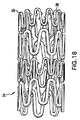
しかるに、処置対象の生体組織の表面積が、医用デバイスの外表面の全領域の表面積より小さいのであれば、複数の非構造的エレメントを、その医用デバイスの外表面の全領域に亘って分布するように配置しておく必要はない。例えば、医用デバイスがステントである場合などには、その医用デバイスを、複数のストラットと複数の非構造的エレメントとで画成された外表面を有する筒状部分を備えたものとすることができる。そして、複数の非構造的エレメントを、例えば図17に示したように、周方向に非対称的に分布するように配置したものとすることができ、同図に模式図で示したステント32では、その外表面のうちの参照番号33で示した部分だけに複数の非構造的エレメントを配置してある。即ち、この図においては、外表面のうちの矩形部分だけに非構造的エレメントが分布している。図18に示したステントは、その外表面のうちの矩形部分においてのみ、ストラットに非構造的エレメントを設けたものである。前記矩形部分は、筒状部分の長手方向軸に平行に延在するものとすることができ、また、前記筒状部分と同じ長さを有するものとすることができる。前記矩形部分は、前記外表面の全領域のうちの、約10%〜約90%に相当するものとすることが好ましい。 However, if the surface area of the tissue to be treated is less than the surface area of the entire area of the outer surface of the medical device, the plurality of non-structural elements are distributed over the entire area of the outer surface of the medical device. There is no need to place it in. For example, when the medical device is a stent, the medical device may include a cylindrical portion having an outer surface defined by a plurality of struts and a plurality of non-structural elements. . And, for example, as shown in FIG. 17, a plurality of non-structural elements can be arranged so as to be distributed asymmetrically in the circumferential direction. In the stent 32 shown in the schematic diagram in FIG. A plurality of non-structural elements are arranged only in the portion indicated by reference numeral 33 on the outer surface. That is, in this figure, nonstructural elements are distributed only in the rectangular portion of the outer surface. The stent shown in FIG. 18 is a structure in which a non-structural element is provided on a strut only in a rectangular portion of its outer surface. The rectangular portion may extend parallel to the longitudinal axis of the cylindrical portion, and may have the same length as the cylindrical portion. It is preferable that the rectangular portion corresponds to about 10% to about 90% of the entire area of the outer surface.
本発明は更に、以上に述べた医用デバイスを用いて生体組織へ生体活性物質をデリバリーする方法に関するものであり、ここでいう以上に述べた医用デバイスとは、複数のストラットと複数の非構造的エレメントとで画成された外表面を有する筒状部分を備え、前記複数の非構造的エレメントが、前記外表面上に、径方向に非対称的な分布を成すように配置された医用デバイスである。この方法においては、前記医用デバイスを、患者の体内に挿入するようにする。前記複数の非構造的エレメントは、医用デバイスの前記外表面のうちの矩形部分だけに分布するように配置されたものとすることが好ましく、前記医用デバイスを挿入する際には、前記矩形部分が処置対象の生体組織に直接接触するようにする。こうすることによって、処置対象の生体組織に対して、望ましい分布で生体活性物質を供給することが可能となる。一方、処置を施す必要のない生体組織は、より少ない量の生体活性物質に曝露されるだけで済む。 The present invention further relates to a method for delivering a bioactive substance to a biological tissue using the medical device described above. The medical device described above includes a plurality of struts and a plurality of non-structural elements. A medical device having a cylindrical portion having an outer surface defined by the elements, wherein the plurality of non-structural elements are arranged on the outer surface to have a radially asymmetric distribution . In this method, the medical device is inserted into a patient's body. The plurality of non-structural elements are preferably arranged so as to be distributed only on a rectangular portion of the outer surface of the medical device, and when the medical device is inserted, the rectangular portion is Direct contact with the living tissue to be treated. By doing so, it is possible to supply the biologically active substance in a desired distribution to the biological tissue to be treated. On the other hand, living tissue that does not need to be treated need only be exposed to a smaller amount of bioactive substance.
第5.2章 端部領域における生体活性物質の実装容量ないし含有容量をより大きくした医用デバイス
本発明に係る患者の体内に挿入可能な医用デバイスのその他の実施の形態として、複数のストラットにより画成された外表面を有する医用デバイスにおいて、その外表面の中央領域よりも端部領域の方で、単位長さ外表面あたりの生体活性物質の実装容量ないし含有容量を、より大きくした医用デバイスがある。より詳しくは、このような医用デバイスの1つの実施の形態においては、中央領域よりも端部領域の方で、単位長さ外表面あたりの各々のストラットの利用可能表面積をより大きなものにしている。また、このような医用デバイスの別の実施の形態では、中央領域よりも端部領域の方で、生体活性物質に対する単位長さ外表面あたりの親和力をより大きなものにしている。
As installing capacity to other embodiments of the insertable medical device into a patient's body according to containing capacity larger the medical device invention of the biological active substance in the 5.2 end region, fractionated by a plurality of struts In the medical device having an outer surface formed, there is a medical device in which the mounting capacity or the content capacity of the bioactive substance per unit length outer surface is larger in the end region than in the central region of the outer surface. is there. More particularly, in one embodiment of such a medical device, the available surface area of each strut per unit length outer surface is greater in the end region than in the central region. . In another embodiment of such a medical device, the affinity per unit length outer surface for the bioactive substance is made larger in the end region than in the central region.
また、このような本発明の医用デバイスは、生体活性物質を既に備えたものを製造メーカーが製品として出荷するようにしてもよく、或いは、生体活性物質を備えていないものを製品として出荷するようにしてもよい。このような本発明の医用デバイスが、生体活性物質を備えていない製品として出荷される場合には、処置実施者(医師や看護士など)がその医用デバイスに生体活性物質を塗布するようにすればよい。いずれの場合にせよ、このような医用デバイスでは、外表面の中央領域よりも端部領域の方で、単位長さ外表面あたりの生体活性物質の実装容量ないし含有容量がより大きなものとなっているため、単にその医用デバイスに生体活性物質を塗布するだけで、端部領域の方により大量の生体活性物質が実装されることになり、それゆえ、端部領域と中央領域とで生体活性物質を塗布する方法を異ならせる必要はない。従って、処置実施者が、生体活性物質を含有するコーティング用配合材料をその医用デバイスの外表面に塗布する際には、例えば浸漬塗布法などの方法を用いて単に塗布を行うだけで、単位長さ外表面あたりの生体活性物質の量が、中央領域よりも端部領域の方においてより多くなる。 In addition, such a medical device of the present invention may be shipped by a manufacturer as a product that already includes a bioactive substance, or may be shipped as a product that does not include a bioactive substance. It may be. When such a medical device of the present invention is shipped as a product that does not include a bioactive substance, a procedure practitioner (such as a doctor or a nurse) applies a bioactive substance to the medical device. That's fine. In any case, in such a medical device, the mounting capacity or content capacity of the bioactive substance per unit length of the outer surface is larger in the end region than in the central region of the outer surface. Therefore, simply applying a bioactive substance to the medical device will result in a larger amount of bioactive substance being mounted in the end region, and hence the bioactive substance in the end region and the central region. It is not necessary to apply a different method for coating. Accordingly, when a treatment practitioner applies a coating compound containing a bioactive substance to the outer surface of the medical device, the unit is simply applied by using, for example, a dip coating method. The amount of bioactive substance per outer surface is greater in the end region than in the central region.
尚、ここでいう「単位長さ外表面」における長さとは、外表面の一方の端縁上の一点と外表面の他方の端縁上の一点とを結び、外表面に沿って延在する仮想直線上における長さをいう。従って、例えば、「単位長さ外表面あたりの容量」、「単位長さ外表面あたりの利用可能表面積」、それに「単位長さ外表面あたりの量」というとき、それらは、かかる仮想直線の単位長さあたりの容量、利用可能表面積、及び量のことを意味している。 In addition, the length in the “unit length outer surface” referred to here connects one point on one edge of the outer surface and one point on the other edge of the outer surface, and extends along the outer surface. The length on the virtual straight line. Thus, for example, when “capacity per unit length outer surface”, “available surface area per unit length outer surface”, and “quantity per unit length outer surface”, they are units of such virtual straight lines. By volume per length, surface area available, and quantity.
第5.2.1章 端部領域において利用可能表面積をより大きくした医用デバイス
既述のごとく、1つの実施の形態に係る医用デバイスでは、中央領域よりも端部領域の方で、単位長さ外表面あたりの利用可能表面積をより大きなものにしている。ここでいう「利用可能表面積」とは、生体活性物質を含有するコーティング用配合材料をその表面にコーティングすることができるという意味で利用可能な表面の、表面積のことである。
As the medical devices described above was larger available surface area in the first 5.2.1 end region, in the medical device according to one embodiment, the direction of the end region than in the central area, unit length The available surface area per outer surface is made larger. As used herein, “available surface area” refers to the surface area of the surface that can be used in the sense that the surface can be coated with a coating compounding material containing a bioactive substance.
端部領域における利用可能表面積をより大きなものとするための1つの方法は、医用デバイスの外表面を画成する材料の使用量を、端部領域の方でより多くすることである。例えば、医用デバイスが複数のストラットを備えたものであるならば、それらストラットに複数の非構造的エレメントを付加することによって端部領域における単位長さ外表面あたりの利用可能表面積を増大させることができる。非構造的エレメントについては、既に説明したとおりである(第5.1.1章を参照されたい)。そして、中央領域よりも端部領域の方で、単位長さ外表面あたりの非構造的エレメントの個数をより多くすればよい。また、中央領域には、より少ない個数の非構造的エレメントを備えるようにしてもよいが、全く非構造的エレメントを備えないようにしてもよい。 One way to increase the available surface area in the end region is to use more material in the end region that defines the outer surface of the medical device. For example, if the medical device is equipped with a plurality of struts, the available surface area per unit length outer surface in the end region can be increased by adding a plurality of non-structural elements to the struts. it can. Non-structural elements are as already described (see Chapter 5.1.1). Then, the number of non-structural elements per unit length outer surface may be increased in the end region than in the central region. Further, the central region may be provided with a smaller number of non-structural elements, but may not be provided with any non-structural elements.
更に、ストラットそれ自体の表面積を増大させることによっても、利用可能表面積を増大させることができる。例えば、図15に示した波形ストラット30は、図5に示した直線状ストラットと比べて、単位長さあたり表面積をより大きなものとすることができる。また、図16に示した、ある部分31を太くしたストラットのように、平均線径を増大させたストラットでは、平均線径が小さいストラットと比べて、やはり単位長さあたり表面積をより大きなものとすることができる。更にまた、端部領域の外表面が、より大きな利用可能表面積を持つようにするための方法として、ストラットの表面を粗面化するという方法や、ストラットの表面に刻み目や溝を形成するという方法がある。以上に述べた波形ストラット、広くまたは太くしたストラット、刻み目、及び溝は、それらがステントの構造的な機能に影響を及ぼさない限り、様々な形状のものとすることができる。例えば、以上に述べた様々な構造は、自己拡張ステントの自己拡張を阻害したり、患者の身体に害を及ぼすものであってはならない。以上に述べた波形ストラット、刻み目、及び溝は、レーザーアブレーション法によって製作することができる。
Furthermore, the available surface area can also be increased by increasing the surface area of the strut itself. For example, the
中央領域よりも端部領域の方で生体活性物質の実装容量ないし含有容量をより大きくした医用デバイスの別の実施の形態としては、外表面の端部領域の多孔度を高め、外表面の中央領域の多孔度を比較的低く抑えたものがある。尚、中央領域は全く細孔を持たない非多孔質のものとしてもよい。例えば、図19において、円45及び円47の中に示したのは、夫々、ステント40の中央領域44及び端部領域46におけるストラット42の外表面の拡大部分図である。中央領域44のストラットの外表面よりも、端部領域46のストラットの外表面の方が、空孔48をより多く含んでいる。この実施の形態では、中央領域44よりも端部領域46の方で、単位長さ外表面あたりの利用可能表面積がより大きなものとなっており、それは、空孔48が存在することによって、利用可能表面積が増大しているからである。
As another embodiment of the medical device in which the mounting capacity or content capacity of the bioactive substance is larger in the end region than in the central region, the porosity of the end region on the outer surface is increased and the center of the outer surface is increased. Some have a relatively low porosity in the region. The central region may be non-porous with no pores at all. For example, in FIG. 19, shown in a
外表面の端部領域を多孔質のものとするには、外表面の端部領域それ自体を多孔質材料で形成するようにしてもよく、または、端部領域を非多孔質材料で形成した後に、その端部領域を多孔質コーティング層で被覆するようにしてもよい。例えば、燒結金属によって多孔質金属製ストラットを製作することができ、その場合には、金属の粉体粒子を型成形やプレスによって所望の形状に成形した上で、その成形体をその金属の融点より僅かに低い温度にまで加熱する。粉体粒子の粒径、及び/または、成形体の寸法、及び/または、加熱温度を異ならせることによって多孔度を様々に変更することができる。また、多孔質金属製ストラットは金属フィラメントまたはファイバを用いて製作することもできる。これに関しては、例えば米国特許第5,843,172号公報(発明者:Yan)などを参照されたい。同米国特許公報には、多孔質金属製ストラットの様々な具体例が開示されており、同米国特許公報の内容はこの言及をもって本願開示に組込まれたものとする。 In order to make the end region of the outer surface porous, the end region of the outer surface itself may be formed of a porous material, or the end region is formed of a non-porous material. Later, the end region may be covered with a porous coating layer. For example, porous metal struts can be produced from sintered metal, in which case the metal powder particles are molded into a desired shape by molding or pressing, and the molded product is then melted into the melting point of the metal. Heat to a slightly lower temperature. The porosity can be variously changed by changing the particle diameter of the powder particles and / or the size of the compact and / or the heating temperature. Porous metal struts can also be made using metal filaments or fibers. For this, refer to, for example, US Pat. No. 5,843,172 (inventor: Yan). Various specific examples of porous metal struts are disclosed in the US Patent Publication, and the contents of the US Patent Publication are incorporated herein by reference.
外表面の端部領域を多孔質のものとする方法として、多孔質コーティング層を形成するという方法もある。多孔質コーティング層を形成するには、例えば、ポリマーと、溶離可能な粒子材料と、溶剤との混合物を表面に塗布して層を形成し、その後に、その層から溶離可能な粒子材料を溶離するようにすればよい。以下に、本発明の多孔質コーティング層を形成するために有用な適当な材料及び方法について詳細に説明する。 As a method for making the end region of the outer surface porous, there is a method of forming a porous coating layer. In order to form a porous coating layer, for example, a layer is formed by applying a mixture of a polymer, an eluting particulate material, and a solvent to the surface, and then eluting the particulate material from the layer. You just have to do it. In the following, suitable materials and methods useful for forming the porous coating layer of the present invention will be described in detail.
多孔質コーティング層を形成するための適当なポリマーは、例えば、生体安定性及び生体適合性を有するポリマーであり、これらの性質は特に、その医用デバイスが体内に挿入されているとき、ないしは植込まれているときに必要とされる性質であり、これらの性質を備えることによって、生体組織に刺激を与えることを回避することができる。このようなポリマーの具体例としては、例えば、ポリウレタン類、ポリイソブチレン及びそのコポリマー類、シリコン類、それにポリエステル類などがあり、またこれらに限定されるものではなく、更にその他にも様々な適当なポリマーがある。その他の適当なポリマーとしては、ポリオレフィン類、ポリイソブチレン、エチレン・αオレフィン・コポリマー類、アクリル系ポリマー類及びコポリマー類、ポリ塩化ビニルなどのハロゲン化ビニルのポリマー類及びコポリマー類、ポリビニルメチルエーテルなどのポリビニルエーテル類、ポリフッ化ビニリデンやポリ塩化ビニリデンなどのポリハロゲン化ビニリデン類、ポリアクリロニトリル、ポリビニルケトン類、ポリスチレンなどのポリビニル芳香族類、ポリビニルアセテートなどのポリビニルエステル類、ビニルモノマー類のコポリマー類、エチレン・メタクリル酸メチル・コポリマー類などのビニルモノマー類とオレフィン類とのコポリマー類、アクリロニトリル・スチレン・コポリマー類、ABS樹脂類、エチレン・ビニルアセテート・コポリマー類、ナイロン66やポリカプロラクトンなどのポリアミド類、アルキド樹脂類、ポリカーボネート類、ポリオキシエチレン類、ポリイミド類、ポリエーテル類、エポキシ樹脂類、ポリウレタン類、レーヨン・トリアセテート、セルロース、酢酸セルロース、酪酸セルロース、酢酸酪酸セルロース、セロファン、硝酸セルロース、プロピオン酸セルロース、セルロースエーテル類、カルボキシメチルセルロース、コラーゲン類、キチン類、ポリ乳酸、ポリグリコール酸、それに、ポリ乳酸・ポリエチレンオキサイド・コポリマー類などがある。ポリマー材料は、医用デバイスの例えば伸縮部分などのように機械的条件が過酷な部分にも塗布されるため、エラストマーとしての性質を有するポリマーのうちから選択することが好ましく、そのようなポリマーには、例えば、シリコン類(ポリシロキサン類や置換ポリシロキサン類など)、ポリウレタン類、熱可塑性エラストマー類、エチレン・酢酸ビニル・コポリマー類、ポリオレフィン系エラストマー類、それにEPDMラバー類がある。ポリマーを選択するに際しては、医用デバイスの拡張可能な部分に荷重ないし応力が作用したときにも、当該部分の表面にコーティング層が良好に被着した状態が維持されるようなポリマーを選択するようにする。また、多孔質コーティング層は、1種類のポリマー材料によって形成することも可能であるが、2種類以上のポリマー材料を様々に組み合わせて形成するようにしてもよい。 Suitable polymers for forming the porous coating layer are, for example, biostable and biocompatible polymers, and these properties are particularly relevant when the medical device is inserted into the body or implanted. It is a property that is required when it is rare, and by providing these properties, it is possible to avoid stimulating living tissue. Specific examples of such polymers include, but are not limited to, polyurethanes, polyisobutylene and copolymers thereof, silicones, and polyesters, and various other suitable types. There is a polymer. Other suitable polymers include polyolefins, polyisobutylene, ethylene / α-olefin copolymers, acrylic polymers and copolymers, vinyl halide polymers and copolymers such as polyvinyl chloride, and polyvinyl methyl ether. Polyvinyl ethers, polyvinyl halides such as polyvinylidene fluoride and polyvinylidene chloride, polyacrylonitrile, polyvinyl ketones, polyvinyl aromatics such as polystyrene, polyvinyl esters such as polyvinyl acetate, copolymers of vinyl monomers, ethylene・ Copolymers of vinyl monomers such as methyl methacrylate copolymers and olefins, acrylonitrile / styrene copolymers, ABS resins, ethylene / vinyl copolymers Tate copolymers, polyamides such as nylon 66 and polycaprolactone, alkyd resins, polycarbonates, polyoxyethylenes, polyimides, polyethers, epoxy resins, polyurethanes, rayon triacetate, cellulose, cellulose acetate, Examples include cellulose butyrate, cellulose acetate butyrate, cellophane, cellulose nitrate, cellulose propionate, cellulose ethers, carboxymethylcellulose, collagens, chitins, polylactic acid, polyglycolic acid, and polylactic acid / polyethylene oxide copolymers. Since the polymer material is also applied to a part having a severe mechanical condition such as a stretchable part of a medical device, it is preferable to select from polymers having an elastomeric property. Examples include silicones (polysiloxanes and substituted polysiloxanes), polyurethanes, thermoplastic elastomers, ethylene / vinyl acetate copolymers, polyolefin elastomers, and EPDM rubbers. When selecting a polymer, a polymer should be selected so that when a load or stress is applied to the expandable portion of the medical device, the coating layer is satisfactorily applied to the surface of the portion. To. In addition, the porous coating layer can be formed of one kind of polymer material, but may be formed by combining two or more kinds of polymer materials in various combinations.
ポリマーに混合する溶離可能な粒子材料には、例えば、酸化ポリエチレン、ポリエチレングリコール、酸化ポリエチレン/酸化ポリプロピレン・コポリマー類、ポリヒドロキシエチルメタクリレート、ポリビニルピロリドン、ポリアクリルアミド及びそのコポリマー類、塩化ナトリウムなどの塩類、糖類、それに、ヘパリンなどの溶離可能な生体活性物質があり、またこれらに限定されず、更にその他の様々なものがある。ポリマーに混合する溶離可能な粒子材料の量は、多孔質コーティング層の全体に対して、約20重量%〜約90重量%とすることが好ましい。更に、外表面の端部領域に形成するコーティング層の多孔度を高めるために、外表面の中央領域に多孔質コーティング層を形成するために用いる溶離可能な粒子材料の量よりも、外表面の端部領域にコーティング層を形成するために用いる溶離可能な粒子材料の量の方を多くするようにしてもよい。その具体的な一例は、例えば、溶離可能な粒子材料の成分量を、中央領域を被覆する多孔質コーティング層を形成するためには約0%〜約40%とし、端部領域を被覆する多孔質コーティング層を形成するためには約50%〜約90%とするというものである。更に、溶離可能な粒子材料を平均粒径の大きなものとすることによって、更に多孔度の高いコーティング層を実現することができる。その具体的な一例は、例えば、端部領域を覆う多孔質コーティング層を形成するために用いる粒子材料の平均粒径は60μm〜100μmとし、一方、中央領域を覆う多孔質コーティング層を形成するために用いる粒子材料の平均粒径は0〜約30μmとするというものである。 Elutable particulate materials mixed with the polymer include, for example, polyethylene oxide, polyethylene glycol, polyethylene oxide / polypropylene copolymers, polyhydroxyethyl methacrylate, polyvinyl pyrrolidone, polyacrylamide and copolymers thereof, salts such as sodium chloride, There are saccharides and bioactive substances that can be eluted such as heparin, but are not limited to these, and there are various other substances. The amount of eluable particulate material mixed with the polymer is preferably about 20% to about 90% by weight relative to the total porous coating layer. Furthermore, in order to increase the porosity of the coating layer formed in the end region of the outer surface, the outer surface is more than the amount of eluable particulate material used to form the porous coating layer in the central region of the outer surface. The amount of eluable particulate material used to form the coating layer in the end region may be increased. One specific example is, for example, that the amount of the eluting particulate material is about 0% to about 40% for forming a porous coating layer covering the central region, and the porous region covering the end region is formed. In order to form a quality coating layer, it is about 50% to about 90%. Furthermore, a coating layer with higher porosity can be realized by making the eluting particle material have a large average particle diameter. A specific example thereof is, for example, that the average particle diameter of the particulate material used to form the porous coating layer covering the end region is 60 μm to 100 μm, while the porous coating layer covering the central region is formed. The average particle size of the particulate material used in the method is 0 to about 30 μm.
ポリマーと溶離可能な粒子材料とを含有する混合材料であるスラリーを調製するために用いる溶剤は、そのポリマーを溶解して溶液とすることができ、しかも、使用する生体活性物質の治療特性を変化させたり、その治療特性に悪影響を及ぼしたりすることのない溶剤である。有用な溶剤の具体例を挙げるならば、例えば、ポリマーとしてシリコン類を用いる場合には、テトラヒドロフラン(THF)、クロロホルム、それにジクロロメタンなどが挙げられる。ポリマー及び溶離可能な粒子材料を含有する配合材料を医用デバイスの夫々の部分へ塗布する方法としては様々な方法を用いることができる。その具体例を挙げるならば、例えば、その配合材料を噴霧塗布法によって医用デバイスに塗布することも可能であり、その配合材料の中へ医用デバイスを浸漬するという方法を用いることもできる。医用デバイスにコーティングを施す方法は、当業者の知悉するところのものである。 The solvent used to prepare the slurry, which is a mixed material containing the polymer and eluting particulate material, can dissolve the polymer into a solution and change the therapeutic properties of the bioactive substance used. And does not adversely affect its therapeutic properties. Specific examples of useful solvents include, for example, tetrahydrofuran (THF), chloroform, and dichloromethane when using silicon as the polymer. Various methods can be used to apply the compounded material containing the polymer and eluable particulate material to the respective portions of the medical device. If the specific example is given, the compounding material can also be apply | coated to a medical device by the spray application method, and the method of immersing a medical device in the compounding material can also be used, for example. Methods for applying coatings to medical devices are known to those skilled in the art.
多孔質コーティング層の厚さは、約25μm〜0.5mmの範囲内の様々な厚さとすることができ、好ましい厚さは、約30μm〜100μmである。コーティング用配合材料を医用デバイスに塗布したならば、続いてそれに硬化処理を施して、粒子材料を含有したポリマーを生成し、溶剤を蒸散させる。 The thickness of the porous coating layer can vary from about 25 μm to 0.5 mm, with a preferred thickness being about 30 μm to 100 μm. Once the coating formulation has been applied to the medical device, it is subsequently subjected to a curing process to produce a polymer containing particulate material and evaporate the solvent.
粒子材料をポリマーから溶離するには、溶剤を用いる。それには、例えば、医用デバイスを溶剤の中に浸漬して粒子材料を溶離するなどの方法を用いる。粒子材料を溶離する方法はこればかりではなく、当業者には周知の様々な方法を用いることができる。いかなる溶剤を使用するかは、その溶剤に対する溶離可能な粒子材料の溶解性によって決まる。例えば、ヘパリンなどの水溶性の粒子材料には、水を用いることができる。有機溶剤に溶解する溶離可能な粒子材料には、そのような有機溶剤を用いればよい。適当な溶剤の具体例としては、エタノールや、ジメチルスルフォキシドなどがあり、またこれらのみに限定されず、その他にも使用可能な溶剤が存在する。 A solvent is used to elute the particulate material from the polymer. For this purpose, for example, a method of immersing the medical device in a solvent and eluting the particulate material is used. The method for eluting the particulate material is not limited to this, and various methods well known to those skilled in the art can be used. Which solvent is used depends on the solubility of the eluable particulate material in that solvent. For example, water can be used for a water-soluble particulate material such as heparin. Such an organic solvent may be used as the eluable particulate material that dissolves in the organic solvent. Specific examples of suitable solvents include ethanol, dimethyl sulfoxide, and the like, but are not limited thereto, and other usable solvents exist.
多孔質コーティング層を形成する方法の別の具体例として、ポリアミド、パリレン、またはパリレン誘導体を含有するコーティング層を、無触媒蒸着法によって形成するという方法がある。これに関しては米国特許第6,299,604号公報(発明者:Ragheb et al.)を参照されたい。尚、同米国特許公報の開示内容はこの言及をもって本願開示に組込まれたものとする。 As another specific example of the method for forming the porous coating layer, there is a method in which a coating layer containing polyamide, parylene, or a parylene derivative is formed by a non-catalytic vapor deposition method. In this regard, see US Pat. No. 6,299,604 (Inventor: Ragheb et al.). It should be noted that the disclosure of the US Patent Gazette is incorporated herein by reference.
本発明の別の実施の形態として、端部領域と中央領域とを含めた表面全体を同一組成の多孔質コーティング層で被覆し、ただし、端部領域においては、その多孔質コーティング層の厚さを中央領域よりも厚くしたものがある。このようにするには、例えば、表面全体に亘って多孔質コーティング層を形成した後に、中央領域をシースで覆い、端部領域だけに、更にもう1層の多孔質コーティング層を重ねて形成するなどすればよい。この場合、多孔質コーティング層の厚さは、例えば、端部領域では約80μm〜約0.5mmとし、中央領域では約10μm〜40μmとするとよい。端部領域では多孔質コーティング層を形成している材料の量が中央領域より多くなるため、外表面の中央領域よりも端部領域の方で、生体活性物質の実装容量ないし含有容量がより大きなものとなる。 As another embodiment of the present invention, the entire surface including the end region and the central region is covered with a porous coating layer having the same composition, provided that the thickness of the porous coating layer is provided in the end region. Is thicker than the central region. In order to do this, for example, after forming a porous coating layer over the entire surface, the central region is covered with a sheath, and another porous coating layer is formed only on the end region. And so on. In this case, the thickness of the porous coating layer may be, for example, about 80 μm to about 0.5 mm in the end region and about 10 μm to 40 μm in the central region. Since the amount of the material forming the porous coating layer is larger in the end region than in the central region, the mounting capacity or contained capacity of the bioactive substance is larger in the end region than in the central region of the outer surface. It will be a thing.
第5.2.2章 端部領域において生体活性物質に対する親和力をより大きくした医用デバイス
先に説明した本発明の医用デバイスの別の実施の形態では、外表面の中央領域よりも端部領域の方で、生体活性物質に対する親和力をより大きなものにしている。これについて更に具体的に説明すると、端部領域は第1の母材料を備えたものとし、中央領域は第2の母材料を備えたものとしている。第1の母材料は第2の母材料と比べて、使用する生体活性物質に対する親和力がより大きなものであり、それによって、中央領域よりも端部領域の方で、単位長さ外表面あたりの実装可能ないし含有可能な生体活性物質の量が、より多くなるようにしている。また、この実施の形態では、外表面の端部領域を第1の母材料で形成し、外表面の中央領域を第2の母材料で形成するようにしてもよい。ただし、好ましいのは、外表面の端部領域と中央領域との両方を、第1の母材料と第2の母材料とのいずれでもない別の材料でまず形成し、しかる後に、外表面の端部領域は、第1の母材料から成るコーティング層で被覆し、外表面の中央領域は、第2の母材料から成るコーティング層で被覆するという方法である。
In another embodiment of the medical device of the present invention described in 5.2.2 Section end region an affinity for bioactive substances larger the medical device location, than the central region of the outer surface of the end region On the other hand, the affinity for the bioactive substance is increased. More specifically, the end region is assumed to be provided with the first base material, and the central region is assumed to be provided with the second base material. The first base material has a greater affinity for the bioactive substance used than the second base material, so that the per unit length outer surface is greater in the end region than in the central region. The amount of bioactive substance that can be mounted or contained is increased. In this embodiment, the end region of the outer surface may be formed of the first base material, and the central region of the outer surface may be formed of the second base material. However, it is preferred that both the edge region and the central region of the outer surface are first formed of another material that is neither the first matrix material nor the second matrix material, and then the outer surface surface The end region is covered with a coating layer made of a first matrix material, and the central region of the outer surface is covered with a coating layer made of a second matrix material.
一般的に、使用する生体活性物質が、例えばヘパリンなどの親水性のものである場合には、親水性の大きな材料から成る母材料の方が、親水性の小さな母材料と比べて、その生体活性物質に対するより大きな親和力を持つことになる。これとは逆に、使用する生体活性物質が、例えばパクリタクセル、アクチノマイシン、シロリムス(ラパマイシン)、タクロリムス、エベロリムス、デキサメタゾンなどの疎水性のものである場合には、疎水性の大きな母材料の方が、疎水性の小さな母材料と比べて、その生体活性物質に対するより大きな親和力を持つことになる。 In general, when the bioactive substance to be used is a hydrophilic substance such as heparin, the base material made of a material having a large hydrophilicity is compared with the base material having a small hydrophilicity. It will have a greater affinity for the active substance. On the other hand, if the bioactive substance used is hydrophobic, such as paclitaxel, actinomycin, sirolimus (rapamycin), tacrolimus, everolimus, dexamethasone, the more hydrophobic matrix is preferred. It will have a greater affinity for the bioactive substance compared to a less hydrophobic matrix.
適当な疎水性ポリマーの具体例としては、例えば以下に列挙するものがあり、ただしそれらのみに限定されず、その他にも様々な適当な疎水性ポリマーが存在する。具体例として先ず、ポリオレフィン類を挙げることができ、これに該当するものには、例えば、ポリエチレン、ポリプロピレン、ポリ(1−ブテン)、ポリ(2−ブテン)、ポリ(1−ペンテン)、ポリ(2−ペンテン)、ポリ(3−メチル・1−ペンテン)、ポリ(4−メチル・1−ペンテン)、ポリ(イソプレン)、ポリ(4−メチル・1−ペンテン)、エチレン・プロピレン・コポリマー類、エチレン・プロピレン・ヘキサジエン・コポリマー類、エチレン・酢酸ビニル・コポリマー類、2種類以上のポリオレフィン類の混合体、それに、2種類以上の不飽和モノマーから成るランダム・コポリマー類及びブロック・コポリマー類などがある。また、スチレン系ポリマー類が挙げられ、これに該当するものには、例えば、ポリ(スチレン)、ポリ(2−メチルスチレン)、約20モルパーセント以下のアクリロニトリルを含有するスチレン・アクリロニトリル・コポリマー類、それに、スチレン・2,2,3,3−テトラフルオロプロピルメタクリレート・コポリマー類などがある。また、ハロゲン化炭化水素系ポリマー類が挙げられ、これに該当するものには、例えば、ポリ(クロロトリフルオロエチレン)、クロロトリフルオロエチレン・テトラフルオロエチレン・コポリマー類、ポリ(ヘキサフルオロプロピレン)、ポリ(テトラフルオロエチレン)、テトラフルオロエチレン、テトラフルオロエチレン・エチレン・コポリマー類、ポリ(トリフルオロエチレン)、ポリ(フッ化ビニル)、それに、ポリ(フッ化ビニリデン)などがある。また、ビニル系ポリマー類が挙げられ、これに該当するものには、例えば、ポリ(酪酸ビニル)、ポリ(デカン酸ビニル)、ポリ(ドデカン酸ビニル)、ポリ(ヘキサデカン酸ビニル)、ポリ(ヘキサン酸ビニル)、ポリ(プロピオン酸ビニル)、ポリ(オクタン酸ビニル)、ポリ(ヘプタフルオロイソプロポキシエチレン)、ポリ(ヘプタフルオロイソプロポキシプロピレン)、それに、ポリ(メタクリロニトリル)などがある。また、アクリル系ポリマー類が挙げられ、これに該当するものには、例えば、ポリ(酢酸n−ブチル)、ポリ(アクリル酸エチル)、ポリ(1−クロロジフルオロメチル)アクリル酸テトラフルオロエチル、ポリジ(クロロフルオロメチル)アクリル酸フルオロメチル、ポリ(1,1−アクリル酸ジヒドロヘプタフルオロブチル)、ポリ(1,1−アクリル酸ジヒドロペンタフルオロイソプロピル)、ポリ(1,1−アクリル酸ジヒドロペンタデカフルオロオクチル)、ポリ(アクリル酸ヘプタフルオロイソプロピル)、ポリ5−(ヘプタフルオロイソプロポキシ)アクリル酸ペンチル、ポリ11−(ヘプタフルオロイソプロポキシ)アクリル酸ウンデシル、ポリ2−(ヘプタフルオロプロポキシ)アクリル酸エチル、それに、ポリ(アクリル酸ノナフルオロイソブチル)などがある。また、メタクリル系ポリマー類が挙げられ、これに該当するものには、例えば、ポリ(メタクリル酸ベンジル)、ポリ(メタクリル酸n−ブチル)、ポリ(メタクリル酸イソブチル)、ポリ(メタクリル酸t−ブチル)、ポリ(メタクリル酸t−ブチルアミノエチル)、ポリ(メタクリル酸ドデシル)、ポリ(メタクリル酸エチル)、ポリ(メタクリル酸2−エチルヘキシル)、ポリ(メタクリル酸n−ヘキシル)、ポリ(メタクリル酸フェニル)、ポリ(メタクリル酸n−プロピル)、ポリ(メタクリル酸オクタデシル)、ポリ(メタクリル酸1,1−ジヒドロペンタデカフルオロオクチル)、ポリ(メタクリル酸ヘプタフルオロイソプロピル)、ポリ(メタクリル酸ヘプタデカフルオロオクチル)、ポリ(メタクリル酸1−ヒドロテトラフルオロエチル)、ポリ(メタクリル酸1,1−ジヒドロテトラフルオロプロピル)、ポリ(メタクリル酸1−ヒドロヘキサフルオロイソプロピル)、それに、ポリ(メタクリル酸t−ノナフルオロブチル)などがある。また、ポリエステル類が挙げられ、これに該当するものには、例えば、ポリ(テレフタル酸エチレン)や、ポリ(テレフタル酸ブチレン)などがある。また、縮合系ポリマー類が挙げられ、これに該当するものには、例えば、ポリウレタン類や、シロキサン・ウレタン・コポリマー類などがある。また、ポリ有機シロキサン類が挙げられ、このポリマー材料は、Rを置換または非置換の一価の炭化水素ラジカルとし、aの値を1または2とするとき、RaSiO4−a/2で表されるシロキサン基が反復することを特徴とするポリマー材料である。また、天然産の疎水性ポリマーが挙げられ、これに該当するものとしては、例えばゴムなどがある。 Specific examples of suitable hydrophobic polymers include those listed below, for example, but are not limited thereto, and there are various other suitable hydrophobic polymers. Specific examples include polyolefins, and examples thereof include polyethylene, polypropylene, poly (1-butene), poly (2-butene), poly (1-pentene), poly ( 2-pentene), poly (3-methyl-1-pentene), poly (4-methyl-1-pentene), poly (isoprene), poly (4-methyl-1-pentene), ethylene-propylene copolymers, Ethylene / propylene / hexadiene copolymers, ethylene / vinyl acetate copolymers, mixtures of two or more polyolefins, random copolymers and block copolymers of two or more unsaturated monomers . Also included are styrenic polymers, such as poly (styrene), poly (2-methylstyrene), styrene-acrylonitrile copolymers containing up to about 20 mole percent acrylonitrile, There are styrene-2,2,3,3-tetrafluoropropyl methacrylate copolymers and the like. In addition, halogenated hydrocarbon-based polymers may be mentioned, and examples thereof include poly (chlorotrifluoroethylene), chlorotrifluoroethylene / tetrafluoroethylene copolymers, poly (hexafluoropropylene), Examples include poly (tetrafluoroethylene), tetrafluoroethylene, tetrafluoroethylene-ethylene copolymers, poly (trifluoroethylene), poly (vinyl fluoride), and poly (vinylidene fluoride). Examples of vinyl polymers include poly (vinyl butyrate), poly (vinyl decanoate), poly (vinyl dodecanoate), poly (vinyl hexadecanoate), and poly (hexane). Acid vinyl), poly (vinyl propionate), poly (vinyl octoate), poly (heptafluoroisopropoxyethylene), poly (heptafluoroisopropoxypropylene), and poly (methacrylonitrile). Acrylic polymers are also included. Examples of such polymers include poly (n-butyl acetate), poly (ethyl acrylate), poly (1-chlorodifluoromethyl) tetrafluoroethyl acrylate, (Chlorofluoromethyl) fluoromethyl acrylate, poly (1,1-dihydroheptafluorobutyl acrylate), poly (1,1-dihydropentafluoroisopropyl acrylate), poly (1,1-acrylate dihydropentadecafluoro) Octyl), poly (heptafluoroisopropyl acrylate), poly 5- (heptafluoroisopropoxy) pentyl acrylate, poly 11- (heptafluoroisopropoxy) undecyl acrylate, poly 2- (heptafluoropropoxy) ethyl acrylate, Also, Poly (Acry Acid nonafluoroisobutyl butyl) and the like. Further, methacrylic polymers can be mentioned, and examples of such polymers include poly (benzyl methacrylate), poly (n-butyl methacrylate), poly (isobutyl methacrylate), poly (t-butyl methacrylate). ), Poly (t-butylaminoethyl methacrylate), poly (dodecyl methacrylate), poly (ethyl methacrylate), poly (2-ethylhexyl methacrylate), poly (n-hexyl methacrylate), poly (phenyl methacrylate) ), Poly (n-propyl methacrylate), poly (octadecyl methacrylate), poly (1,1-dihydropentadecafluorooctyl methacrylate), poly (heptafluoroisopropyl methacrylate), poly (heptadecafluorooctyl methacrylate) ), Poly (1-hydrotetramethacrylate) Ruoroechiru), poly (methacrylic acid, 1,1-dihydro-tetrafluoropropyl), poly (methacrylic acid 1 hydro hexafluoroisopropyl) Besides, poly (t-nonafluorobutyl methacrylate) and the like. Polyesters are also included, and examples of such polyesters include poly (ethylene terephthalate) and poly (butylene terephthalate). Condensation-type polymers may be mentioned, and examples of such polymers include polyurethanes and siloxane / urethane copolymers. Polyorganosiloxanes may also be mentioned. This polymer material is represented by RaSiO 4-a / 2, where R is a substituted or unsubstituted monovalent hydrocarbon radical, and the value of a is 1 or 2. It is a polymer material characterized by repeating siloxane groups. In addition, naturally occurring hydrophobic polymers are listed, and examples of such polymers include rubber.
適当な親水性モノマーの具体例としては、例えば以下に列挙するものがあり、ただしそれらのみに限定されず、その他にも様々な適当な親水性モノマーが存在する。具体例として先ず、(メタ)アクリル酸、ないしはそのアルカリ金属塩類もしくはアンモニウム塩類を挙げることができる。また、(メタ)アクリルアミドや、(メタ)アクリロニトリルが挙げられる。また、以上のポリマーに、例えばマレイン酸やフマル酸などの不飽和二塩基酸類、または不飽和二塩基酸類の半エステル類、または不飽和二塩基酸類の付加エステル類もしくは半エステル類のアルカリ金属塩類もしくはアンモニウム塩類などを付加したものが挙げられる。また、以上のポリマーに、例えば、2−アクリルアミド−2−メチルプロパンスルホン酸や、2−(メタ)アクリロイレタンスルホン酸などの不飽和スルホン酸類、または不飽和スルホン酸類のアルカリ金属塩類もしくはアンモニウム塩類などを付加したものが挙げられる。また、(メタ)アクリル酸2−ヒドロキシエチルや、(メタ)アクリル酸2−ヒドロキシプロピルが挙げられる。 Specific examples of suitable hydrophilic monomers include, for example, those listed below, but are not limited thereto, and various other suitable hydrophilic monomers exist. Specific examples include (meth) acrylic acid or alkali metal salts or ammonium salts thereof. Moreover, (meth) acrylamide and (meth) acrylonitrile are mentioned. Further, for example, unsaturated dibasic acids such as maleic acid and fumaric acid, half esters of unsaturated dibasic acids, addition esters or unsaturated esters of unsaturated dibasic acids, and alkali metal salts of the above polymers. Or what added ammonium salt etc. is mentioned. Moreover, for example, 2-acrylamido-2-methylpropanesulfonic acid, unsaturated sulfonic acids such as 2- (meth) acryloylethanesulfonic acid, or alkali metal salts or ammonium salts of unsaturated sulfonic acids. And the like. Moreover, 2-hydroxyethyl (meth) acrylate and 2-hydroxypropyl (meth) acrylate are mentioned.
親水性ポリマーの具体例としては、更に、ポリビニルアルコールが挙げられる。ポリビニルアルコールは複数の親水基を含むことができ、含まれる親水基の具体例としては、例えば、ヒドロキシル基、アミド基、カルボキシル基、アミノ基、アンモニウム基、それにスルホニル基(−SO3)などがある。親水性ポリマーの具体例としては、更に、以下に列挙するものがあり、無論それらのみに限定されるものではない。先ず、デンプン、多糖類、及びそれらに関連したセルロース系ポリマー類が挙げられる。また、ポリアルキレングリコール類、それに、例えばポリエチレンオキサイドなどのポリアルキレンオキサイド類が挙げられる。また、例えばアクリル酸、メタクリル酸、それにマレイン酸などのエチレン系不飽和カルボン酸類をポリマー化したものや、エチレン系不飽和カルボン酸類と例えばアルキレングリコール類などの多価アルコール類とから誘導された部分エステル類をポリマー化したものが挙げられる。また、アクリルアミド類から誘導されたホモポリマー類及びコポリマー類が挙げられる。また、ビニルピロリドンのホモポリマー類及びコポリマー類が挙げられる。 Specific examples of the hydrophilic polymer further include polyvinyl alcohol. Polyvinyl alcohol can contain a plurality of hydrophilic groups. Specific examples of the hydrophilic groups contained include, for example, a hydroxyl group, an amide group, a carboxyl group, an amino group, an ammonium group, and a sulfonyl group (—SO 3 ). is there. Specific examples of the hydrophilic polymer further include those listed below, and of course not limited thereto. First, starch, polysaccharides, and cellulosic polymers related to them are mentioned. In addition, polyalkylene glycols, and polyalkylene oxides such as polyethylene oxide are exemplified. In addition, a polymer derived from an ethylenically unsaturated carboxylic acid such as acrylic acid, methacrylic acid and maleic acid, or a portion derived from an ethylenically unsaturated carboxylic acid and a polyhydric alcohol such as an alkylene glycol The thing which polymerized ester is mentioned. Also included are homopolymers and copolymers derived from acrylamides. Also included are vinylpyrrolidone homopolymers and copolymers.
第1の母材料及び第2の母材料は、親水性ポリマーを用いて調製されることもあれば、疎水性ポリマーを用いて調製されることもあり、更には、疎水性ポリマーと親水性ポリマーとが適宜の割合で混合して用いられることもある。その具体例を挙げるならば、生体活性物質が親水性のものである場合には、例えば、第1の母材料を約55%〜約100%の親水性ポリマーと約45%〜約0%の疎水性ポリマーとを混合して調製し、第2の母材料を約55%〜約100%の疎水性ポリマーと約45%〜約0%の親水性ポリマーとを混合して調製することができる。こうすることで、第1の母材料は第2の母材料と比べて、より大量の親水性ポリマーを含有することになる。一方、生体活性物質が疎水性のものである場合には、例えば、第1の母材料を約55%〜約95%の疎水性ポリマーと約45%〜約5%の親水性ポリマーとを混合して調製し、第2の母材料を約55%〜約95%の親水性ポリマーと約45%〜約5%の疎水性ポリマーとを混合して調製することができる。こうすることで、第1の母材料は第2の母材料と比べて、より大量の疎水性ポリマーを含有することになる。 The first base material and the second base material may be prepared using a hydrophilic polymer, may be prepared using a hydrophobic polymer, and further, the hydrophobic polymer and the hydrophilic polymer may be prepared. And may be used in a mixture at an appropriate ratio. For example, when the bioactive substance is hydrophilic, for example, the first matrix may be about 55% to about 100% hydrophilic polymer and about 45% to about 0%. The second matrix can be prepared by mixing about 55% to about 100% hydrophobic polymer and about 45% to about 0% hydrophilic polymer. . By doing so, the first base material contains a larger amount of the hydrophilic polymer than the second base material. On the other hand, when the bioactive substance is hydrophobic, for example, the first base material is mixed with about 55% to about 95% hydrophobic polymer and about 45% to about 5% hydrophilic polymer. And a second matrix can be prepared by mixing about 55% to about 95% hydrophilic polymer and about 45% to about 5% hydrophobic polymer. By doing so, the first base material will contain a larger amount of hydrophobic polymer than the second base material.
先にも述べたように、本発明の医用デバイスは、その外表面を領域ごとに別々の母材料で被覆したものとすることができ、即ち、端部領域は第1の母材料で被覆し、中央領域は第2の母材料で被覆したものとすることができる。第1の母材料を形成するために調製した配合材料を医用デバイスの表面に塗布するには、任意の塗布方法を用いればよく、例えば、噴霧塗布法、浸漬塗布法、回転塗布法、それに、静電塗布法などを用いることができる。同様に、第2の母材料を形成するために調製した配合材料を塗布するにも、それら塗布方法を用いることができる。また、第1の母材料を形成するための配合材料を外表面の端部領域に塗布する際には、中央領域を覆って、中央領域には第1の母材料がコーティングされないようにするとよい。これに続いて、第2の母材料を形成するための配合材料を中央領域に塗布する際には、端部領域を覆うようにすればよい。また別の実施の形態として、第2の母材料を形成するための配合材料を、中央領域と端部領域とを含めた外表面の全領域に塗布し、その後に、中央領域を覆った状態で、端部領域に第1の母材料を形成するための配合材料を塗布するという方法を用いることも可能である。 As previously mentioned, the medical device of the present invention can have its outer surface coated with a separate matrix for each region, i.e., the end region is coated with a first matrix. The central region may be coated with a second base material. In order to apply the compounding material prepared to form the first base material to the surface of the medical device, any application method may be used, for example, spray application method, dip coating method, spin coating method, An electrostatic coating method or the like can be used. Similarly, these coating methods can be used to apply the compounding material prepared to form the second base material. Further, when the compounding material for forming the first base material is applied to the end region of the outer surface, it is preferable to cover the central region so that the first base material is not coated on the central region. . Subsequently, when the compounding material for forming the second base material is applied to the central region, the end region may be covered. In another embodiment, the compounding material for forming the second base material is applied to the entire outer surface including the central region and the end region, and then the central region is covered. Thus, it is possible to use a method of applying a compounding material for forming the first base material in the end region.
第1及び第2の母材料を形成するための夫々の配合材料を外表面に塗布したならば、その外表面に対して硬化処理を施して、それら母材料から成るコーティング層を形成する。それら母材料から成るコーティング層の厚さは、例えば、約25μm〜約0.5mmとする。好ましい厚さは、約30μm〜100μmである。 When the respective compounding materials for forming the first and second base materials are applied to the outer surface, the outer surface is subjected to a curing treatment to form a coating layer made of the base materials. The thickness of the coating layer made of these base materials is, for example, about 25 μm to about 0.5 mm. A preferred thickness is from about 30 μm to 100 μm.
第5.2.3章 端部領域において生体活性物質を実装ないし含有するための化学結合材料の量をより多くした医用デバイス
本発明の更に別の実施の形態では、外表面の中央領域よりも外表面の端部領域の方において、生体活性物質の実装容量ないし含有容量をより大きくするための手段として、生体活性物質を医用デバイスの外表面に結合させるために用いる化学結合材料の使用量を、外表面の端部領域においてより多くするようにしている。この実施の形態について更に詳しく説明すると、外表面の中央領域及び端部領域を化学結合材料で被覆するようにしており、しかもその際に、中央領域よりも端部領域の方において、単位長さ外表面あたりの化学結合材料の実装量ないし含有量をより多くするようにしている。化学結合材料は、生体活性物質が外表面に付着できるようにする薬剤である。この「結合材料」としては、当業界において周知の様々な結合力のうちの任意の結合力によって生体活性物質に結合することのできる物質を用いればよく、ここでいう周知の結合力とは、例えば、ファンデルワールス力、イオン結合力、共有結合力、水素結合力、それに、化学架橋力などであり、また、これらのみに限定されず、更にその他の結合力を利用した結合材料も存在する。
In yet another embodiment of the medical device invention as more the amount of chemical binding materials for implementing or contain biological active substance In the 5.2.3 end region, than in the central region of the outer surface In the end region of the outer surface, as a means for increasing the mounting capacity or the containing capacity of the bioactive substance, the amount of the chemical binding material used for binding the bioactive substance to the outer surface of the medical device is reduced. , More in the end region of the outer surface. This embodiment will be described in more detail. The central region and the end region of the outer surface are covered with a chemical bonding material, and in this case, the unit length is more in the end region than in the central region. The mounting amount or content of the chemical bonding material per outer surface is increased. A chemical binding material is an agent that allows a bioactive substance to adhere to an outer surface. As the “binding material”, a substance that can be bonded to a bioactive substance by any bonding force among various bonding forces well known in the art may be used. For example, van der Waals force, ionic bond force, covalent bond force, hydrogen bond force, chemical cross-linking force, and the like, but not limited to these, there are also binding materials using other bond forces. .
化学結合材料による結合の具体例として、例えば米国特許第5,356,433号公報(発明者:Rowland et al.)には、金属表面にアミン機能を持つ有機シランのコーティング層を形成し、それに続いてカルボジイミドを結合剤として使用して多糖類をコーティングすることによって、その金属表面に多糖類を固定できるということが開示されている。本発明において、このようなアミン機能を持つ有機シランを結合材料として使用する場合には、単位長さ外表面あたりのその有機シランの量を、中央領域よりも端部領域の方においてより多くするようにすればよい。それによって、生体活性物質である多糖類を、端部領域の方により大量に結合させることができる。 As a specific example of bonding by a chemical bonding material, for example, in US Pat. No. 5,356,433 (inventor: Rowland et al.), A coating layer of organosilane having an amine function is formed on a metal surface, followed by carbodiimide. It is disclosed that the polysaccharide can be immobilized on the metal surface by coating the polysaccharide using it as a binder. In the present invention, when an organic silane having such an amine function is used as a binding material, the amount of the organic silane per unit length outer surface is larger in the end region than in the central region. What should I do? Thereby, the polysaccharide which is a bioactive substance can be bound in a larger amount toward the end region.
もう1つの具体例として、米国特許第5,336,518号公報(発明者Narayanan ee al.)には、高周波(RF)プラズマ蒸着法によってメタクリル酸ヘプタフルオロブチル(HFBMA)のコーティング層を形成し、続いて、水蒸気存在下のRFプラズマによってその表面に機能基を形成し、更に続いてカルボジイミドを用いて多糖類をコーティングすることによって、表面に多糖類を固定できることが開示されている。本発明においては、結合材料であるHFBMAを、端部領域の方により大量に蒸着することによって、生体活性物質である多糖類をより大量に結合できるようにする。 As another specific example, US Pat. No. 5,336,518 (Narayanan ee al.) Forms a coating layer of heptafluorobutyl methacrylate (HFBMA) by radio frequency (RF) plasma deposition, It is disclosed that a polysaccharide can be immobilized on a surface by forming a functional group on the surface by RF plasma in the presence of water vapor and then coating the polysaccharide with carbodiimide. In the present invention, a large amount of HFBMA, which is a binding material, is deposited in a larger amount toward the end region, so that a polysaccharide, which is a bioactive substance, can be bound in a larger amount.
第5.3章 生体活性物質の実装容量ないし含有容量を周方向において非対称的に増強した医用デバイス
第5.3.1章 非構造的エレメントを周方向に非対称的な分布で配置した医用デバイス
既述のごとく、医用デバイスにおける生体活性物質の実装容量ないし含有容量を増大させる方法の1つに、利用可能表面積を拡大するという方法がある。そして、本発明の医用デバイスの1つの実施の形態では、利用可能表面積の拡大を、外表面の端部領域だけで行うのではなく、外表面の全体に亘って行い、ただし、周方向に非対称的に行うようにしている。そのようにした実施の形態の1つにおいては、外表面に非構造的エレメント(非構造的エレメントについては、5.1.3章を参照されたい)を付加することによる利用可能表面積の拡大を、周方向に非対称的に行うようにしている。その具体例を挙げるならば、例えば、外表面の全体のうちの矩形部分だけに、非構造的エレメントを設けるようにする。この矩形部分は、例えば、筒状部分の長手方向軸に平行に延在し、筒状部分と同じ長さを有するものとすることができる。また、この矩形部分は、外表面の全領域のうちの約25%〜約75%に相当するものとすることが好ましい。また、このような医用デバイスを用いて生体組織へ生体活性物質をデリバリーする方法については、第5.1.3章を参照されたい。
Chapter 5.3 medical devices already placing the medical device Chapter 5.3.1 nonstructural elements that implement capacity to contain capacity asymmetrically enhanced in the circumferential direction of the biological active substance circumferentially asymmetrical distribution As described above, one of the methods for increasing the mounting capacity or the containing capacity of the bioactive substance in the medical device is to increase the available surface area. And in one embodiment of the medical device of the present invention, the available surface area is enlarged not only in the end region of the outer surface but over the entire outer surface, but asymmetric in the circumferential direction. I try to do it. In one such embodiment, the available surface area can be increased by adding non-structural elements to the outer surface (see Chapter 5.1.3 for non-structural elements). The asymmetrical operation is performed in the circumferential direction. If the specific example is given, a nonstructural element will be provided only in the rectangular part of the whole outer surface, for example. This rectangular portion can extend, for example, parallel to the longitudinal axis of the cylindrical portion and have the same length as the cylindrical portion. Further, it is preferable that the rectangular portion corresponds to about 25% to about 75% of the entire area of the outer surface. For the method of delivering a bioactive substance to living tissue using such a medical device, refer to Chapter 5.1.3.
第5.3.2章 利用可能表面積または親和力を周方向に非対称的に拡大または増強した医用デバイス
本発明の医用デバイスの別の実施の形態においては、その医用デバイスが筒状部分を備えており、その筒状部分は複数のストラットで構成され、外表面を有している。そして、その外表面の一部において利用可能表面積を拡大しまたは生体活性物質に対する親和力を増強することによって、利用可能表面積の分布を、または生体活性物質に対する親和力の分布を、周方向に非対称的なものにしている。この周方向に非対称的な分布の具体例については、既述の章(第5.3.1章)を参照されたい。また、利用可能表面積の拡大または生体活性物質に対する親和力の増強をどのようにして行えばよいかという方法についても、既述の章(5.2.1章及び5.2.2章)を参照されたい。更に、このような医用デバイスを用いて生体組織へ生体活性物質をデリバリーする方法については、第5.1.3章を参照されたい。
Chapter 5.3.2 Medical Device with Asymmetrically Expanded or Enhanced Available Surface Area or Affinity in the Circumferential Direction In another embodiment of the medical device of the present invention, the medical device comprises a tubular portion The cylindrical portion is composed of a plurality of struts and has an outer surface. Then, by expanding the available surface area or enhancing the affinity for the bioactive substance on a part of the outer surface, the distribution of the available surface area or the affinity distribution for the bioactive substance is asymmetric in the circumferential direction. I'm making things. Please refer to the previous chapter (Chapter 5.3.1) for specific examples of this circumferentially asymmetric distribution. See also the previous chapters (chapter 5.2.1 and 5.2.2) on how to increase the available surface area or increase the affinity for bioactive substances. I want to be. Furthermore, refer to Chapter 5.1.3 for a method of delivering a bioactive substance to living tissue using such a medical device.
第5.4章 適当な医用デバイス
本発明の医用デバイスは、患者の体内に挿入可能な医用デバイスである。即ち、本発明の医用デバイスは、その少なくとも一部分が、一時的に患者の体内に挿入されるか、或いは、半永久的または永久的に患者の体内に植込まれるものである。本発明の医用デバイスは、患者の体内に挿入可能な筒状部分を備えたものとすることが好ましい。その場合の医用デバイスの筒状部分は、完全な円筒形である必要はない。例えば、筒状部分の断面形状は、四角形や三角形をはじめとする任意の形状とすることができ、円形だけに限られるものではない。
Chapter 5.4 Suitable Medical Device The medical device of the present invention is a medical device that can be inserted into a patient's body. That is, at least a part of the medical device of the present invention is temporarily inserted into the patient's body, or semipermanently or permanently implanted in the patient's body. The medical device of the present invention preferably includes a cylindrical portion that can be inserted into a patient's body. The cylindrical part of the medical device in that case need not be perfectly cylindrical. For example, the cross-sectional shape of the cylindrical portion can be any shape including a quadrangle and a triangle, and is not limited to a circle.
本発明を適用するのに適した医用デバイスの具体例としては、例えば、ステント、手術用ステープル、中心静脈カテーテルや中心動脈カテーテルなどの種々のカテーテル、ガイドワイヤ、カニューラ、心ペースメーカのリードないしリードチップ、心細動除去器のリードないしリードチップ、植込型血管アクセスポート、血管グラフトなどの種々のグラフト、大動脈内バルーンポンプ、人工心弁、心臓血管縫合糸、全人工心臓、それに心室補助ポンプなどがあり、また、これらに限定されるものではなく、更にその他にも様々な適当な医用デバイスが存在する。 Specific examples of medical devices suitable for application of the present invention include, for example, various catheters such as stents, surgical staples, central venous catheters and central arterial catheters, guide wires, cannulaes, and lead or lead chips of cardiac pacemakers Various types of grafts such as cardiac defibrillator leads or lead tips, implantable vascular access ports, vascular grafts, intra-aortic balloon pumps, artificial heart valves, cardiovascular sutures, total artificial hearts, and ventricular assist pumps In addition, there are various other suitable medical devices, which are not limited to these.
本発明を適用するのに特に適した医用デバイスは、当業者に周知のあらゆる種類の医用ステントである。適当な医用ステントの具体例としては、例えば、自己拡張型ステントやバルーン拡張型ステントをはじめとする種々の血管ステントが挙げられる。本発明を適用することが有用な自己拡張型ステントの具体例としては、例えば米国特許第4,655,771号公報(発明者:Wallsten)、米国特許第4,954,126号公報(発明者:Wallsten)、それに米国特許第5,061,275号公報(発明者:Wallsten et al.)などに示されている自己拡張型ステントがある。本発明を適用することが適当なバルーン拡張型ステントの具体例としては、例えば米国特許第4,733,665号公報(発明者:Palmaz)、米国特許第4,800,882号公報(発明者:Gianturco)、米国特許第4,886,062号公報(発明者:Wiktor)、それに米国特許第5,449,373号公報(発明者:Pinchasik et al.)などに示されているバルーン拡張型ステントがある。更に、分岐型ステントも、本発明を適用するのに適した医用デバイスのうちの1つである。幾つかの好適な実施の形態では、本発明を適用するのに適した適当なステントを、Express(登録商標)ステントとしている。具体的な実施の形態にかかるステントは、Express(登録商標)ステント、及びExpress 2(登録商標)ステントである(これらのステントは、米国、マサチューセッツ州、ナティックに所在のボストン・サイエンティフィック・コーポレーションの製品である)。
Medical devices that are particularly suitable for applying the present invention are all types of medical stents well known to those skilled in the art. Specific examples of suitable medical stents include various vascular stents including self-expandable stents and balloon expandable stents. Specific examples of the self-expanding stent to which the present invention is useful include, for example, US Pat. No. 4,655,771 (inventor: Wallsten), US Pat. No. 4,954,126 (inventor: Wallsten), and US Pat. There is a self-expanding stent disclosed in US Pat. No. 5,061,275 (inventor: Wallsten et al.). Specific examples of balloon expandable stents to which the present invention is suitable include US Pat. No. 4,733,665 (inventor: Palmaz), US Pat. No. 4,800,882 (inventor: Gianturco), US Pat. No. 4,886,062 No. (Inventor: Wiktor) and U.S. Pat. No. 5,449,373 (Inventor: Pinchasik et al.). Furthermore, a bifurcated stent is one of the medical devices suitable for applying the present invention. In some preferred embodiments, a suitable stent suitable for applying the present invention is an Express® stent. Stents according to specific embodiments are Express® stents and
本発明を適用するのに適した医用デバイスは、ポリマー材料及び/または金属材料を用いて製作することができる。適当なポリマー材料の具体例としては、例えば、ポリウレタン及びそのコポリマー類、シリコン及びそのコポリマー類、エチレン酢酸ビニル、ポリテレフタル酸エチレン、熱可塑性エラストマー、ポリ塩化ビニル、ポリオレフィン類、セルロース化合物、ポリアミド類、ポリエステル類、ポリスルホン類、ポリテトラフルオロエチレン類、アクリロニトリル・ブタジエン・スチレン・コポリマー類、アクリル化合物、ポリアクト酸、ポリクリコール酸、ポリカプロラクトン、ポリアセタール、ポリ乳酸、ポリ乳酸・ポリエチレンオキサイド・コポリマー類、ポリカーボネート、セルロース、コラーゲン、それにキチン類などがある。また、適当な金属材料の具体例としては、例えば、チタン系の金属材料及び合金材料(ニチノール、ニッケル−チタン合金、感熱型形状記憶合金材料など)、ステンレス鋼、プラチナ、タンタル、ニッケル−クロム、コバルト−クロム−ニッケル合金を含むある種のコバルト合金(エルジロイ7、フィノックス7など)、それに、金合金ないしプラチナ合金などがある。更には、PCT特許第WO94/16646号公報に開示されているクラッド複合フィラメントなども、適当な金属材料である。 Medical devices suitable for applying the present invention can be fabricated using polymeric and / or metallic materials. Specific examples of suitable polymer materials include, for example, polyurethane and copolymers thereof, silicon and copolymers thereof, ethylene vinyl acetate, ethylene polyterephthalate, thermoplastic elastomer, polyvinyl chloride, polyolefins, cellulose compounds, polyamides, Polyesters, polysulfones, polytetrafluoroethylenes, acrylonitrile / butadiene / styrene copolymers, acrylic compounds, polyactic acid, polyglycolic acid, polycaprolactone, polyacetal, polylactic acid, polylactic acid / polyethylene oxide copolymers, polycarbonate, There are cellulose, collagen, and chitins. Specific examples of suitable metal materials include titanium-based metal materials and alloy materials (Nitinol, nickel-titanium alloy, heat-sensitive shape memory alloy materials, etc.), stainless steel, platinum, tantalum, nickel-chromium, There are certain types of cobalt alloys including cobalt-chromium-nickel alloys (Elgiloy 7, Finox 7, etc.), gold alloys and platinum alloys. Furthermore, a clad composite filament disclosed in PCT Patent No. WO94 / 16646 is also a suitable metal material.
更に、本発明を適用するのに適した医用デバイスは、外表面を有するものであり、しかも、その外表面は、端部領域と中央領域とを有するものである。ここでいう「外表面」とは、医用デバイスの表面のうちの、生体組織に対して曝される部分の表面を意味している。例えば、図20に示した筒状構造体は、ステント40の模式図であるが、このステント40の外表面に該当するのは、このステント40の表面のうちの、このステント40即ち医用デバイスを体内に挿入したときに生体組織に直接接触する表面をいう。また、医用デバイスが、図19に示したように、複数のストラット42によって構成されたステント40である場合には、このステント40の「外表面」とは、ストラット42の表面のうちの、体内管路ないし生体組織に直接接触する表面をいう。
Furthermore, a medical device suitable for applying the present invention has an outer surface, and the outer surface has an end region and a central region. The “outer surface” as used herein refers to the surface of the surface of the medical device that is exposed to the living tissue. For example, the cylindrical structure shown in FIG. 20 is a schematic view of the stent 40. The outer surface of the stent 40 corresponds to the stent 40, that is, the medical device on the surface of the stent 40. A surface that comes into direct contact with living tissue when inserted into the body. Further, when the medical device is a stent 40 composed of a plurality of
また、外表面の「端部領域」とは、外表面のうちの、筒状部分の端縁からある位置までの部分をいい、その部分の長さは、外表面の全長に対して最大で約25%までの長さであり、好ましくは、外表面の全長に対して約3%〜約20%の長さである。その具体例として、例えば、その医用デバイスが、図19ないし図20に示したような、ステント40である場合には、その外表面の端部領域46は、このステントの外表面のうちの、外表面の端縁から延在する長さがeのリング形の部分であり、この長さeは、ステントの外表面の全長αに対して最大で25%までの長さである。図19及び図20では、端部領域をハッチング部分46で表している。
Further, the “end region” of the outer surface refers to a portion of the outer surface from the edge of the cylindrical portion to a certain position, and the length of the portion is the maximum with respect to the entire length of the outer surface. The length is up to about 25%, preferably about 3% to about 20% of the total length of the outer surface. As a specific example, for example, when the medical device is a stent 40 as shown in FIGS. 19 to 20, the
また、外表面の「中央領域」とは、外表面のうちの、以上に規定した端部領域によって両側を挟まれた残りの部分をいう。例えば、図19ないし図20において、中央領域44とは、両側を端部領域によって挟まれた、長さがmのリング形の部分である。
The “central region” of the outer surface refers to the remaining portion of the outer surface sandwiched on both sides by the end region defined above. For example, in FIGS. 19 to 20, the
第5.5章 外表面に生体活性物質を塗布する方法
既述のごとく、第5.2.1章〜第5.2.3章で説明した実施の形態の医用デバイスは、その医用デバイスが製品として出荷される時点で既に生体活性物質が塗布されているようにしてもよく、或いは、その医用デバイスを患者の体内に挿入する直前に医療従事者が生体活性物質を塗布するようにしてもよい。また、第5.1.1章〜第5.1.3章、第5.2.1章〜第5.2.3章、及び、第5.3.1章〜第5.3.2章に記載したように構成した医用デバイスの外表面に、生体活性物質を塗布する際には、その生体活性物質を単独で塗布することもでき、また、ポリマー材料などの他の材料と組み合わせて塗布することもできる。例えば、中央領域よりも端部領域の方において、単位長さ外表面あたりの利用可能表面積をより大きなものとする実施の形態では、生体活性物質を外表面に塗布する際に、生体活性物質とポリマー材料とを含有する配合材料をコーティングするという方法を用いることができる。より詳しくは、生体活性物質とポリマー材料とを含有するコーティング用配合材料を調製して、それを外表面に塗布するという方法を用いることができる。また別法として、この実施の形態でも、生体活性物質を単独で外表面に塗布するという方法を用いることも可能である。
As methods described above for applying a bioactive substance to Chapter 5.5 outer surface, a medical device embodiment described in Section 5.2.1 through Chapter 5.2.3, the medical device The bioactive substance may already be applied at the time of shipment as a product, or the medical staff may apply the bioactive substance immediately before inserting the medical device into the patient's body. Good. Also, chapters 5.1.1 to 5.1.3, chapters 5.2.1 to 5.2.3, and chapters 5.3.1 to 5.3.2 When a bioactive substance is applied to the outer surface of a medical device configured as described in the chapter, the bioactive substance can be applied alone or in combination with other materials such as polymer materials. It can also be applied. For example, in an embodiment in which the available surface area per unit length outer surface is larger in the end region than in the central region, when applying the bioactive material to the outer surface, A method of coating a compounding material containing a polymer material can be used. More specifically, a method of preparing a compounding material for coating containing a bioactive substance and a polymer material and applying it to the outer surface can be used. Alternatively, in this embodiment, it is also possible to use a method in which a bioactive substance is applied alone to the outer surface.
生体活性物質に対する親和力を外表面の一部のみにおいて増強するようにした実施の形態や、化学結合材料の含有量を外表面の一部のみにおいて増量するようにした実施の形態などでは、生体活性物質を単独で外表面に塗布するという方法を用いることが好ましい。例えば、外表面の一部において、生体活性物質に対する親和力のより大きな母材料を用いる場合には、外表面の母材料のコーティング層の上に重ねて生体活性物質を塗布するようにするとよい。ただし、生体活性物質とポリマー材料とを混合したものを、母材料のコーティング層の上に塗布するという方法を用いることも可能である。更に、母材料として用いるコーティング用配合材料の中に生体活性物質を配合することによって、母材料で構成されるコーティング層が既に生体活性物質を含有しているようにしてもよい。 In an embodiment where the affinity for a bioactive substance is enhanced only on a part of the outer surface, or in an embodiment where the content of the chemical binding material is increased only on a part of the outer surface, the bioactivity It is preferable to use a method in which a substance is applied alone to the outer surface. For example, when a base material having a higher affinity for the bioactive substance is used on a part of the outer surface, the bioactive substance may be applied over the coating layer of the base material on the outer surface. However, it is also possible to use a method in which a mixture of a bioactive substance and a polymer material is applied on the coating layer of the base material. Further, a bioactive substance may be blended in a coating compounding material used as a base material so that the coating layer composed of the base material already contains the bioactive substance.
第5.5.1章 コーティング用配合材料及びコーティング層
本発明に用いるのに適したコーティング用配合材料を、医用デバイスの表面に塗布してコーティング層を形成する際には、任意の塗布方法を用いることができる。塗布方法の具体例を挙げるならば、例えば噴霧塗布法、浸漬塗布法、回転塗布法、それに静電塗布法などを挙げることができ、更に、バイオ分子を表面に固定するための最近開発された全ての化学的方法を用いることができる。
5.5.1 Coating compounding material and coating layer When a coating compounding material suitable for use in the present invention is applied to the surface of a medical device to form a coating layer, any coating method may be used. Can be used. Specific examples of the coating method include spray coating method, dip coating method, spin coating method, electrostatic coating method, and the like. Further, recently developed for immobilizing biomolecules on the surface. All chemical methods can be used.
本発明に用いるコーティング用配合材料は、例えば、水溶性溶剤または有機溶剤に生体活性物質を溶解した溶液などの形態のものとすることができる。このようなコーティング用配合材料を用いる場合には、その配合材料を表面に塗布して、溶剤を蒸散させるようにすればよい。先に説明したように、医用デバイスの筒状部分の端部領域において、表面積を拡大させたり、親和力を増強したりする場合には、また特に、端部領域を多孔質とする場合には、このように、生体活性物質を溶液としたものを使用するとよい。 The coating compounding material used in the present invention can be in the form of, for example, a solution in which a bioactive substance is dissolved in a water-soluble solvent or an organic solvent. When such a coating compounding material is used, the compounding material may be applied to the surface to evaporate the solvent. As described above, in the end region of the cylindrical portion of the medical device, when the surface area is increased or the affinity is increased, particularly when the end region is made porous, Thus, it is good to use what made the bioactive substance the solution.
更に、本発明に好適に用いることのできるコーティング用配合材料は、例えば、医用デバイスに用いるのに適した溶剤に、ポリマー材料を分散または溶解させ、場合によっては生体活性物質も併せて分散または溶解させた配合材料などであり、医用デバイスに用いるのに適した溶剤は、当業者には周知のものである。コーティング用配合材料を調製するために用いるこの溶剤は、例えば、ポリマー材料を溶解して溶液とし得ると共に、使用する生体活性物質の治療効果特性を変化させたりそれに悪影響を及ぼしたりすることのない溶剤などである。その具体例を挙げるならば、例えば、ポリマー材料がシリコンである場合には、テトラヒドロフラン(THF)、クロロホルム、トルエン、アセトン、イソオクタン、1,1,1−トリクロロエタン、ジクロロメタン、それに、それらの混合物などを、溶剤として使用することができる。 Furthermore, the compounding material for coating that can be suitably used in the present invention includes, for example, a polymer material dispersed or dissolved in a solvent suitable for use in a medical device, and in some cases a bioactive substance is also dispersed or dissolved. Solvents suitable for use in medical devices, such as formulated materials, are well known to those skilled in the art. The solvent used for preparing the coating compound is, for example, a solvent that can dissolve the polymer material into a solution and does not change or adversely affect the therapeutic effect characteristics of the bioactive substance used. Etc. Specific examples thereof include, for example, when the polymer material is silicon, tetrahydrofuran (THF), chloroform, toluene, acetone, isooctane, 1,1,1-trichloroethane, dichloromethane, and a mixture thereof. Can be used as a solvent.
本発明の医用デバイスにおけるコーティングの構成は、複数のコーティング層を様々な組合せで組合せたものとすることも可能である。その具体例として、例えば、第1層と第2層とが異なった生体活性物質を含有している構成とすることができる。また、別の具体例として、第1層と第2層とが同一の生体活性物質を含有しており、ただし異なった濃度で含有している構成とすることもできる。また、1つの実施の形態として、第1層と第2層との一方が生体活性物質を含有していない構成とするのもよい。その具体例を挙げるならば、例えば、生体活性物質を溶解した溶液を表面に塗布して(第1層)乾燥させ、しかる後に、その乾燥した生体活性物質の上に、生体活性物質を含有していないコーティング用配合材料を塗布する(第2層)ようにすればよい。 The configuration of the coating in the medical device of the present invention may be a combination of a plurality of coating layers in various combinations. As a specific example thereof, for example, the first layer and the second layer may have different bioactive substances. As another specific example, the first layer and the second layer may contain the same bioactive substance, but may contain different concentrations. In one embodiment, one of the first layer and the second layer may be configured not to contain a bioactive substance. As a specific example, for example, a solution in which a bioactive substance is dissolved is applied to the surface (first layer) and dried, and then the bioactive substance is contained on the dried bioactive substance. What is necessary is just to make it apply | coat the coating compounding material which is not (2nd layer).
ポリマー材料としては、生体適合性を有し、生体組織に刺激を与えることのない材料を用いるべきである。本発明におけるコーティング用配合材料に用いることのできる好ましいポリマー材料の具体例としては、例えば以下に列挙するものがあり、ただしそれらのみに限定されず、その他にも様々な適当なポリマー材料が存在する。具体例として先ず、ポリカルボン酸類、酢酸セルロースや硝酸セルロースなどのセルロース系ポリマー類、ゼラチン、ポリビニルピロリドン、架橋ポリビニルピロリドン、無水マレイン酸ポリマーなどのポリアンヒロリド類、ポリアミド類、ポリビニルアルコール類、EVAなどのビニルモノマー類のコポリマー類、ポリビニルエーテル類、ポリビニル芳香族化合物、酸化ポリエチレン、グリコースアミノグリカン類、多糖類、ポリエチレンテレフタル酸などのポリエステル類、ポリアクリルアミド類、ポリエーテル類、ポリエーテルスルホン、ポリカーボネート、ポリプロピレンやポリエチレンや高分子量ポリエチレンなどのポリアルキレン類、ポリテトラフルオロエチレンなどのポリハロゲン化アルキレン類、ポリウレタン類、ポリオルソエステル類、蛋白質類、ポリペプチド類、シリコン類、シロキサンポリマー類、ポリ乳酸、ポリグリコール酸類、ポリカプロラクトン、ポリヒドロキシ酪酸吉草酸、スチレン・イソブチレン・コポリマー類、それに、以上に列挙したものの混合物並びにコポリマー類が挙げられる。更にその他の適当なポリマー材料の具体例を挙げるならば、ポリウレタン類(BAYHDROL(登録商標)など)、フィブリン、コラーゲン及びその誘導体、それに、多糖類を挙げることができ、多糖類に該当するものには、例えば、セルロース、デンプン、デキストラン、アルギン酸及びその誘導体、それに、ヒアルロン酸などがあり、また、スクアレンを挙げることができる。更にその他の本発明におけるコーティング用配合材料に用いられるポリマー材料の具体例としては、ポリウレタン類、シリコン類(ポリシロキサン類や置換ポリシロキサン類など)、及びポリエステル類のうちから選択されるポリマー材料が挙げられる。用いることのできる更にその他のポリマー材料の具体例としては、溶解した上で医用デバイスの表面で硬化即ちポリマー化することのできる種々のポリマー材料や、比較的融点が低く、生体活性物質と混合することのできるポリマー材料が挙げられる。更にその他の適当なポリマー材料の具体例としては、殆どの熱可塑性エラストマー類、ポリオレフィン類、ポリイソブチレン、エチレン・αオレフィン・コポリマー類、アクリル系ポリマー類及びコポリマー類、ポリ塩化ビニルなどのハロゲン化ビニルのポリマー類及びコポリマー類、ポリビニルメチルエーテルなどのポリビニルエーテル類、ポリフッ化ビニリデンやポリ塩化ビニリデンなどのポリハロゲン化ビニリデン類、ポリアクリロニトリル、ポリビニルケトン類、ポリスチレンなどのポリビニル芳香族類、ポリビニルアセテートなどのポリビニルエステル類、ビニルモノマー類のコポリマー類、エチレン・メタクリル酸メチル・コポリマー類などのビニルモノマー類とオレフィン類とのコポリマー類、アクリロニトリル・スチレン・コポリマー類、ABS(アクリロニトリル・ブタジエン・スチレン)樹脂類、エチレン・ビニルアセテート・コポリマー類、ナイロン66やポリカプロラクトンなどのポリアミド類、アルキド樹脂類、ポリカーボネート類、ポリオキシエチレン類、ポリイミド類、ポリエーテル類、エポキシ樹脂類、レーヨン・トリアセテート、セルロース、酢酸セルロース、酪酸セルロース、酢酸酪酸セルロース、セロファン、硝酸セルロース、プロピオン酸セルロース、セルロースエーテル類、カルボキシメチルセルロース、コラーゲン類、キチン類、ポリ乳酸、ポリグリコール酸、それに、ポリ乳酸・ポリエチレンオキサイド・コポリマー類、EPDM(エチレン・プロピレン・ジエン)ラバー類、フッ化シリコン類、ポリエチレングリコール、多糖類、リン脂質類、それに、以上に列挙したポリマー材料を組合せたポリマー材料を挙げることができる。 As the polymer material, a material that is biocompatible and does not irritate living tissue should be used. Specific examples of preferable polymer materials that can be used for the coating compounding material in the present invention include, for example, those listed below, but are not limited thereto, and there are various other suitable polymer materials. . As specific examples, first, polycarboxylic acids, cellulose polymers such as cellulose acetate and cellulose nitrate, gelatin, polyvinylpyrrolidone, crosslinked polyvinylpyrrolidone, polyanhydrides such as maleic anhydride polymer, polyamides, polyvinyl alcohols, vinyl such as EVA, etc. Copolymers of monomers, polyvinyl ethers, polyvinyl aromatic compounds, polyethylene oxide, glycolose aminoglycans, polysaccharides, polyesters such as polyethylene terephthalic acid, polyacrylamides, polyethers, polyethersulfone, polycarbonate, polypropylene, Polyalkylenes such as polyethylene and high molecular weight polyethylene, polyhalogenated alkylenes such as polytetrafluoroethylene, polyurethanes, polyols Esters, proteins, polypeptides, silicones, siloxane polymers, polylactic acid, polyglycolic acids, polycaprolactone, polyhydroxybutyric acid valeric acid, styrene / isobutylene copolymers, and mixtures and copolymers of those listed above Kind. Specific examples of other suitable polymer materials include polyurethanes (BAYHDROL (registered trademark), etc.), fibrin, collagen and derivatives thereof, and polysaccharides. Examples thereof include cellulose, starch, dextran, alginic acid and derivatives thereof, and hyaluronic acid, and examples thereof include squalene. Furthermore, specific examples of the polymer material used for the coating compounding material in the present invention include polymer materials selected from polyurethanes, silicons (polysiloxanes and substituted polysiloxanes), and polyesters. Can be mentioned. Specific examples of other polymer materials that can be used include various polymer materials that can be dissolved and cured or polymerized on the surface of a medical device, or mixed with a bioactive substance that has a relatively low melting point. Polymer materials that can be used. Examples of other suitable polymeric materials include most thermoplastic elastomers, polyolefins, polyisobutylene, ethylene / alpha olefin copolymers, acrylic polymers and copolymers, vinyl halides such as polyvinyl chloride. Polymers and copolymers, polyvinyl ethers such as polyvinyl methyl ether, polyvinylidene halides such as polyvinylidene fluoride and polyvinylidene chloride, polyacrylonitrile, polyvinyl ketones, polyvinyl aromatics such as polystyrene, polyvinyl acetate, etc. Polyvinyl esters, copolymers of vinyl monomers, copolymers of olefins with vinyl monomers such as ethylene / methyl methacrylate / copolymers, acrylonitrile / styrene / Polymers, ABS (acrylonitrile butadiene styrene) resins, ethylene vinyl acetate copolymers, polyamides such as nylon 66 and polycaprolactone, alkyd resins, polycarbonates, polyoxyethylenes, polyimides, polyethers , Epoxy resins, rayon triacetate, cellulose, cellulose acetate, cellulose butyrate, cellulose acetate butyrate, cellophane, cellulose nitrate, cellulose propionate, cellulose ethers, carboxymethylcellulose, collagens, chitins, polylactic acid, polyglycolic acid, In addition, polylactic acid / polyethylene oxide copolymers, EPDM (ethylene / propylene / diene) rubbers, silicon fluorides, polyethylene glycol, polysaccharides, Mention may be made of phospholipids and polymer materials in combination with the polymer materials listed above.
特に好ましいポリマー材料としては、ポリアクリル酸を挙げることができ、その入手可能な製品としては、例えばHYDROPLUS(登録商標)(これは、米国、マサチューセッツ州、ナティックに所在の、ボストン・サイエンティフィック・コーポレーションの製品である)がある。また、このポリアクリル酸については、米国特許第5,091,205号公報の中で論じられており、同米国特許公報の開示内容はこの言及をもって本願開示に組込まれたものとする。本発明の最も好適な実施の形態の1つにおいては、ポリマー材料としてポリ乳酸とポリカプロラクトンとのコポリマーが用いられている。 Particularly preferred polymeric materials include polyacrylic acid, and available products include, for example, HYDROPLUS® (which is Boston Scientific, USA, Natick, Massachusetts, USA). Is a product of the Corporation). The polyacrylic acid is discussed in US Pat. No. 5,091,205, and the disclosure of the US patent publication is incorporated herein by reference. In one of the most preferred embodiments of the present invention, a copolymer of polylactic acid and polycaprolactone is used as the polymer material.
例えば伸縮などの過酷な機械的条件に曝される医用デバイスでは、使用するポリマー材料を、エラストマーとしての性質を有するポリマーのうちから選択することが好ましく、そのようなポリマーには、例えば、シリコン類(ポリシロキサン類や置換ポリシロキサン類など)、ポリウレタン類、熱可塑性エラストマー類、エチレン・酢酸ビニル・コポリマー類、ポリオレフィン系エラストマー類、それにEPDMラバー類がある。これらポリマーは、エラストマーとしての性質を有するため、医用デバイスが荷重、応力、ないしは過酷な機械的条件に曝される場合にも、その医用デバイスの表面にコーティング用配合材料が良好に被着した状態が維持される。 For medical devices that are exposed to harsh mechanical conditions such as stretching, it is preferable to select the polymer material to be used from polymers having properties as elastomers, such as silicones. (Polysiloxanes and substituted polysiloxanes), polyurethanes, thermoplastic elastomers, ethylene / vinyl acetate copolymers, polyolefin elastomers, and EPDM rubbers. These polymers have elastomeric properties so that the coating compound is well deposited on the surface of the medical device even when the medical device is exposed to loads, stresses, or harsh mechanical conditions. Is maintained.
放出量を制御しつつ生体活性物質を放出する機能であるコントロールド・リリース機能を備えたコーティング層(コントロールド・リリース・コーティング層)を形成するためには、例えば、適当な疎水性ポリマーを含有するコーティング用配合材料を用いてコーティング層を形成するようにすればよい。その具体例を挙げるならば、生体活性物質を含有するコーティング層の上に、疎水性ポリマーを含有するコーティング層を重ねて形成することによって、それら2つの層の複合層としてのコントロールド・リリース・コーティング層を形成することができる。また、疎水性ポリマーと生体活性物質との混合物を含有するコーティング用配合材料によってコーティング層を形成することによっても、コントロールド・リリース・コーティング層を形成することができる。 In order to form a coating layer with a controlled release function (controlled release coating layer) that releases bioactive substances while controlling the release amount, for example, it contains a suitable hydrophobic polymer The coating layer may be formed using the coating compounding material. For example, a controlled release layer as a composite layer of these two layers is formed by superposing a coating layer containing a hydrophobic polymer on a coating layer containing a bioactive substance. A coating layer can be formed. The controlled release coating layer can also be formed by forming a coating layer with a coating compounding material containing a mixture of a hydrophobic polymer and a bioactive substance.
コーティング層におけるポリマー材料の配合量は、その医用デバイスに用途によって異なる。コーティング層におけるポリマー材料の種類及び目標配合量をどのようにして決定すればよいかは、当業者の知悉するところである。ポリマー材料の配合量は、コーティング用配合材料の全体に対して約1重量%〜約15重量%とすることが好ましい。また、ポリマー材料の配合量は、コーティング用配合材料の全体に対して約1重量%〜約3重量%とすれば、更に好ましい。 The blending amount of the polymer material in the coating layer varies depending on the use of the medical device. One skilled in the art knows how to determine the type of polymer material and the target blending amount in the coating layer. The blending amount of the polymer material is preferably about 1% by weight to about 15% by weight with respect to the entire coating compounding material. Further, the blending amount of the polymer material is more preferably about 1% by weight to about 3% by weight with respect to the entire blending material for coating.
コーティング用配合材料を表面に塗布したならば、それに硬化処理を施して、粒子材料を含有するポリマーを生成し、溶剤を蒸散させる。シリコンをはじめとするある種のポリマーは、比較的低温(例えば室温)で硬化させることができ、そのプロセスは、室温硬化(RTV)プロセスと呼ばれている。より一般的なプロセスは、高温で実施する硬化/蒸散プロセスであり、これは、コーティング用配合材料を塗布した医用デバイスをオーブンに入れて加熱することによって行われる。ポリマーとしてシリコンが使用されている場合には、通常、約90℃以上の温度で加熱処理を行い、その加熱時間は約1〜16時間である。また、コーティング用配合材料の種類によっては、150℃もの高温で加熱処理を行うこともある。加熱処理の処理時間及び処理温度は、無論、使用する具体的なポリマー、薬剤、及び溶剤に応じて異なったものとなる。これらパラメータに必要とされる調節は、当業者の知るところのものである。 Once the coating compound is applied to the surface, it is cured to produce a polymer containing particulate material and the solvent is evaporated. Certain polymers, including silicon, can be cured at relatively low temperatures (eg, room temperature), and the process is referred to as a room temperature cure (RTV) process. A more common process is a curing / evaporation process performed at high temperatures, which is performed by heating the medical device with the coating formulation applied in an oven. When silicon is used as the polymer, the heat treatment is usually performed at a temperature of about 90 ° C. or higher, and the heating time is about 1 to 16 hours. Moreover, depending on the kind of coating compounding material, heat treatment may be performed at a high temperature of 150 ° C. The treatment time and treatment temperature of the heat treatment will of course vary depending on the specific polymer, agent and solvent used. The adjustments required for these parameters are known to those skilled in the art.
コーティング層の厚さに制限はないが、一般的には約25μm〜約0.5mmとする。また、好ましい厚さは約30μm〜100μmである。 The thickness of the coating layer is not limited, but is generally about 25 μm to about 0.5 mm. A preferred thickness is about 30 μm to 100 μm.
第5.5.2章 適当な生体活性物質
本発明に関して使用する「生体活性物質」という用語は、処置薬や麻酔薬などの薬剤、遺伝物質、それに生体物質などを包含する用語であり、それらの同義語として「生体活性物質」という用語を使用するものである。本発明に用いるのに適した適当な処置薬の具体例を挙げるならば、例えば以下に列挙するものなどがあり、ただしそれらのみに限定されず、その他にも適当な処置薬が存在する。先ず挙げられるのは、ヘパリン、ヘパリン誘導体、ウロキナーゼ、デキストロフェニルアラニン・プロリン・アルギニン・クロロメチルケトン(PPack)、エノクサプリン、アンジオペプチン、ヒルジン、アセチルサリチル酸、タクロリムス、エベロリムス、ラパマイシン(シロリムス)、アムロジピン、デキサゾシン、グルココルチコイド、βメタゾン、デキサメタゾン、プレドニゾロン、コルチコステロン、ブデソニド、スルファサラジン、ロシグリタゾン、マイコフェノール酸、メサラミン、パクリタクセル、5−フルオロウラシル、シスプラチン、ビンブラスチン、ビンクリスチン、エポチロン、メトトリキセート、アザチオプリン、アドリアマイシン、ムタマイシン、エンドスタチン、アンジオスタチン、チミジンキナーゼ阻害剤、クラドリビン、リドカイン、ブピバカイン、ロピバカイン、D−Phe−Pro−Argクロロメチルケトン、血小板レセプター拮抗剤、抗トロンビン抗体、抗血小板レセプター抗体、アスピリン、ジピリダモール、プロタミン、ヒルジン、プロスタグランジン阻害剤、血小板凝集阻害剤、トラピジル、リプロスチン、ダニ由来抗血小板ペプチド製剤、5−アザシチジン、血管内皮成長因子、成長因子レセプター、転写アクティベーター、翻訳プロモーター、抗増殖剤、成長因子阻害剤、成長因子レセプター拮抗剤、転写リプレッサー、翻訳リプレッサー、複製阻害剤、阻害性抗体、抗成長因子抗体、成長因子とシトトキシンとを含むバイファンクショナル分子、抗体とシトトキシンとを含むバイファンクショナル分子、コレステロール降下剤、血管拡張剤、内因性血管作動性機序干渉剤、抗酸化剤、プロブコール、抗生剤、ペニシリン、セフォキシチン、オキサシリン、トブラナイシン、血管形成物質、線維芽細胞成長因子、エストロゲン、エストラジオール(E2)、エストリオール(E3)、17−βエストラジオール、ジゴキシン、βブロッカー、カプトプリル、エナロプリル、スタチン類、ステロイド類、ビタミン類、タキソール、パクリタクセル、2’−サクシニール・タキソール、2’−サクシニール・タキソール・トリエタノールアミン、2’−グルタリル・タキソール、2’−グルタリル・タキソール・トリエタノールアミン塩、N−(ジメチルアミノエチル)グルタミンを含む2’−O−エステル、N−(ジメチルアミノエチル)グルタミド・ハイドロクロライド塩を含む2’−O−エステル、ニトログリセリン、酸化二窒素、一酸化窒素、抗生剤、アスピリン、ジギタリス、エストロゲン、エストラジオール、それにグリコシド類である。1つの実施の形態においては、処置薬として平滑筋細胞増殖阻害剤または抗生剤を使用するようにしている。また、好ましい1つの実施の形態においては、処置薬としてタキソール(例えばTaxol(登録商標)など)またはその類似体ないし誘導体を使用するようにしている。また、別の好適な実施の形態においては、処置薬としてパクリタクセルまたはその類似体ないし誘導体を使用するようにしている。また、更に別の好適な実施の形態では、処置薬として抗生剤を使用するようにしており、使用する抗生剤は、例えば、エリトロマイシン、アンフォテリシン、ラパマイシン、アドリアマイシン、等々である。
Chapter 5.5.2 Appropriate Bioactive Substance The term “bioactive substance” used in connection with the present invention is a term encompassing drugs such as treatment drugs and anesthetics, genetic substances, and biological substances. The term “bioactive substance” is used as a synonym. Specific examples of suitable treatment agents suitable for use in the present invention include those listed below, but are not limited thereto, and there are other suitable treatment agents. First, heparin, heparin derivatives, urokinase, dextrophenylalanine / proline / arginine / chloromethyl ketone (PPack), enoxaprine, angiopeptin, hirudin, acetylsalicylic acid, tacrolimus, everolimus, rapamycin (sirolimus), amlodipine, dexazosin, Glucocorticoid, β-metazone, dexamethasone, prednisolone, corticosterone, budesonide, sulfasalazine, rosiglitazone, mycophenolic acid, mesalamine, paclitaxel, 5-fluorouracil, cisplatin, vinblastine, vincristine, epothilone, methotrixate, azathioprine, Statins, angiostatins, thymidine kinase inhibitors Agent, cladribine, lidocaine, bupivacaine, ropivacaine, D-Phe-Pro-Arg chloromethyl ketone, platelet receptor antagonist, antithrombin antibody, antiplatelet receptor antibody, aspirin, dipyridamole, protamine, hirudin, prostaglandin inhibitor, platelet Aggregation inhibitor, trapidil, liprostin, tick-derived antiplatelet peptide preparation, 5-azacytidine, vascular endothelial growth factor, growth factor receptor, transcription activator, translation promoter, antiproliferative agent, growth factor inhibitor, growth factor receptor antagonist, transcription Repressor, translational repressor, replication inhibitor, inhibitory antibody, anti-growth factor antibody, bifunctional molecule containing growth factor and cytotoxin, bifunctional molecule containing antibody and cytotoxin, cholesterol Depressant, Vasodilator, Endogenous vasoactive mechanism interference agent, Antioxidant, Probucol, Antibiotic, Penicillin, Cefoxitin, Oxacillin, Tobranaisin, Angiogenic substance, Fibroblast growth factor, Estrogen, Estradiol (E2) , Estriol (E3), 17-β estradiol, digoxin, β blocker, captopril, enaropril, statins, steroids, vitamins, taxol, paclitaxel, 2′-succinyl taxol, 2′-succinyl taxol triethanol Amine, 2′-glutaryl / taxol, 2′-glutaryl / taxol / triethanolamine salt, 2′-O-ester containing N- (dimethylaminoethyl) glutamine, N- (dimethylaminoethyl) glutamide hydrochloride 2'-O- ester containing, nitroglycerin, nitrous oxide, nitric oxide, an antibiotic, aspirin, digitalis, estrogen, estradiol, glycosides. In one embodiment, a smooth muscle cell growth inhibitor or antibiotic is used as a therapeutic agent. In one preferred embodiment, taxol (for example, Taxol (registered trademark)) or an analog or derivative thereof is used as a therapeutic agent. In another preferred embodiment, paclitaxel or an analog or derivative thereof is used as a therapeutic agent. In still another preferred embodiment, an antibiotic is used as a therapeutic agent. Examples of the antibiotic used include erythromycin, amphotericin, rapamycin, adriamycin, and the like.
また「遺伝物質」とは、例えば、以下に列挙する様々な有用蛋白質をエンコードしているDNA/RNAの、そのDNAまたはRNAであって、しかもヒトの体内に導入することを意図したものをいい、ウイルスベクターと非ウイルスベクターとがあり、またそれらのみに限定されず、更にその他の様々なものがある。 “Genetic material” means, for example, DNA / RNA that encodes various useful proteins listed below, and the DNA or RNA intended to be introduced into the human body. In addition, there are viral vectors and non-viral vectors, and there are various other types without being limited thereto.
また「生体物質」とは、例えば、細胞、酵母菌、バクテリア、蛋白質類、ペプチド類、シトキン類、それに、ホルモン類などを含むものである。ペプチド類ないしは蛋白質類の具体例を挙げるならば、例えば、血管内皮成長因子(VEGF)、トランスフォーミング成長因子(TGF)、線維芽細胞成長因子(FGF)、表皮成長因子(EGF)、軟骨成長因子(CGF)、神経成長因子(NGF)、ケラチン生成細胞成長因子(KGF)、骨格筋成長因子(SGF)、骨芽細胞由来成長因子(BDGF)、肝細胞成長因子(HGF)、インスリン様成長因子(IGF)、サイトカイン成長因子(CFG)、血小板由来成長因子(PDGF)、低酸素症発症因子−1(HIF−1)、幹細胞由来因子(SDF)、幹細胞因子(SCF)、内皮細胞成長サプリメント(ECGS)、顆粒細胞・マクロファージ・コロニー刺激因子(GM−CSF)、成長分化因子(GDF)、インテグリン調節因子(IMF)、カルモジュリン(CaM)、チミジンキナーゼ(TK)、腫瘍壊死因子(TNF)、成長ホルモン(GH)、種々の骨形成蛋白質(BMP)(例えば、BMP−2、BMP−3、BMP−4、BMP−5、BMP−6(Vgr−1)、BMP−7(PO−1)、BMP−8、BMP−9、BMP−10、BMP−11、BMP−12、BMP−14、BMP−15、BMP−16、等々)、マトリックス・メタロプロテイナーゼ(MMP)、マトリックス・メタロプロテイナーゼの組織阻害因子(TIMP)、シトキン類、インターロイキン(例えば、IL−1、IL−2、IL−3、IL−4、IL−5、IL−6、IL−7、IL−8、IL−9、IL−10、IL−11、IL−12、IL−15、等々)、リンフォカイン、インターフェロン、インテグリン、コラーゲン(全種類)、エラスチン、フィブリリン、フィブロネクチン、ビトロネクチン、ラミニン、グリコースアミノグリカン、プロテオグリカン、トランスフェリン、サイトタクチン、細胞接着ドメイン(例えばRGDなど)、それに、テナスチンなどがある。現時点で好適なBMPであると考えられているのは、BMP−2、BMP−3、BMP−4、BMP−5、BMP−6、それに、BMP−7である。これらは二量体蛋白質であり、ホモ二量体とすることも、ヘテロ二量体とすることも、或いはそれらを組合せた形のものとすることもでき、また、他の分子を伴うものとすることも、他の分子を伴わないものとすることもできる。移植部位へ必要な蛋白質をデリバリーするための細胞としては、ヒトの臓器の細胞も用いられ(自己由来細胞と同種異系細胞とのいずれも用いられる)、また、動物細胞(即ち、異種細胞)も用いられ、更には、必要に応じてその細胞に遺伝子操作を施すこともある。デリバリー媒体は、細胞の機能及び生存能力を維持することができるように、必要に応じて適宜調製すればよい。用いられる細胞の具体例を挙げるならば、例えば、前駆細胞(内皮前駆細胞など)、幹細胞(組織幹細胞、造血幹細胞、神経幹細胞など)、間質細胞、実質細胞、未分化細胞、線維芽細胞、マクロファージ、それに、サテライト細胞などがある。 The “biological substance” includes, for example, cells, yeasts, bacteria, proteins, peptides, cytokins, hormones, and the like. Specific examples of peptides or proteins include, for example, vascular endothelial growth factor (VEGF), transforming growth factor (TGF), fibroblast growth factor (FGF), epidermal growth factor (EGF), cartilage growth factor. (CGF), nerve growth factor (NGF), keratinocyte growth factor (KGF), skeletal muscle growth factor (SGF), osteoblast-derived growth factor (BDGF), hepatocyte growth factor (HGF), insulin-like growth factor (IGF), cytokine growth factor (CFG), platelet-derived growth factor (PDGF), hypoxia-onset factor-1 (HIF-1), stem cell-derived factor (SDF), stem cell factor (SCF), endothelial cell growth supplement ( ECGS), granule cells / macrophages / colony stimulating factor (GM-CSF), growth differentiation factor (GDF), integrin Node factor (IMF), calmodulin (CaM), thymidine kinase (TK), tumor necrosis factor (TNF), growth hormone (GH), various bone morphogenetic proteins (BMP) (for example, BMP-2, BMP-3, BMP) -4, BMP-5, BMP-6 (Vgr-1), BMP-7 (PO-1), BMP-8, BMP-9, BMP-10, BMP-11, BMP-12, BMP-14, BMP -15, BMP-16, etc.), matrix metalloproteinase (MMP), matrix metalloproteinase tissue inhibitor (TIMP), cytokins, interleukins (eg IL-1, IL-2, IL-3, IL-4, IL-5, IL-6, IL-7, IL-8, IL-9, IL-10, IL-11, IL-12, IL-15, etc.), phosphorus Okain, interferon, integrin, collagen (all types), elastin, fibrillin, fibronectin, vitronectin, laminin, glycosaminoglycans, proteoglycans, transferrin, cytotactin, cell binding domain (e.g., RGD, etc.), it, and the like Tenasuchin. BMP-2, BMP-3, BMP-4, BMP-5, BMP-6, and BMP-7 are currently considered preferred BMPs. These are dimeric proteins that can be homodimers, heterodimers, or a combination of them, and with other molecules. Or without other molecules. As a cell for delivering a necessary protein to the transplantation site, a human organ cell is used (both autologous cells and allogeneic cells are used), and animal cells (that is, heterologous cells). In addition, the cells may be genetically manipulated as necessary. The delivery medium may be appropriately prepared as necessary so that the function and viability of the cells can be maintained. Specific examples of cells to be used include, for example, progenitor cells (endothelial progenitor cells etc.), stem cells (tissue stem cells, hematopoietic stem cells, neural stem cells etc.), stromal cells, parenchymal cells, undifferentiated cells, fibroblasts, There are macrophages and satellite cells.
その他の非遺伝子治療に用いられる処置薬としては、例えば、以下に列挙するものなどがある。
・抗血栓剤。これに該当するものには、例えば、ヘパリン、ヘパリン誘導体、ウロキナーゼ、それに、PPack(デキストロフェニルアラニン・プロリン・アルギニン・クロロメチルケトン)などがある。
・抗増殖剤。これに該当するものには、例えば、エノクサプリン、アンジオペプチン、または平滑筋細胞の増殖をブロックすることのできる単クローン抗体、ヒルジン、アセチルサリチル酸、タクロリムス、エベロリムス、アムロジピン、それに、デキサゾシンなどがある。
・抗炎症剤。これに該当するものには、例えば、グルココルチコイド、βメタゾン、デキサメタゾン、プレドニソロン、コルチコステロン、ブデソニド、エストロゲン、スルファサラジン、ロシグリタゾン、マイコフェノール酸、それに、メサラミンなどがある。
・抗腫瘍/抗増殖/抗縮瞳剤。これに該当するものには、例えば、5−フルオロウラシル、シスプラチン、ビンブラスチン、ビンクリスチン、エポチロン、メトトリキセート、アザチオプリン、アドリアマイシン、ムタマイシン、エンドスタチン、アンジオスタチン、チミジンキナーゼ阻害剤、クラドリビン、それに、タキソール及びその類似体ないし誘導体などがある。
・麻酔剤。これに該当するものには、例えば、リドカイン、ブピバカイン、それに、ロピバカインなどがある。
・抗凝血剤。これに該当するものには、例えば、D−Phe−Pro−Argクロロメチルケトン、合成物を含むRGDペプチド製剤、ヘパリン、アンチトロンビン製剤、血小板レセプター拮抗剤、抗トロンビン抗体、抗血小板レセプター抗体、アスピリン(アスピリンは更に、鎮痛・解熱・抗炎症剤にも分類される)、ジピリダモール、プロタミン、ヒルジン、プロスタグランジン阻害剤、血小板凝集阻害剤、トラピジルやリプロスチンなどの抗血小板剤、それに、ダニ由来抗血小板ペプチド製剤などがある。
・DNA脱メチル化剤。これに該当するものには、例えば5−アザシチジンなどがあり、この5−アザシチジンは、RNAまたはDNAのメタボライトにも分類され、細胞の成長を阻害し、ある種の癌細胞にアポプトーシスを誘発するものである。
・血管細胞成長プロモーター。これに該当するものには、例えば、成長因子、血管内皮成長因子(VEGF、全ての種類のものが含まれ、従ってVEGF−2も含まれる)、成長因子レセプター、転写アクティベーター、それに、翻訳プロモーターなどがある。
・血管細胞成長阻害剤。これに該当するものには、例えば、抗増殖剤、成長因子阻害剤、成長因子レセプター拮抗剤、転写リプレッサー、翻訳リプレッサー、複製阻害剤、阻害性抗体、抗成長因子抗体、成長因子とシトトキシンとを含むバイファンクショナル分子、それに、抗体とシトトキシンとを含むバイファンクショナル分子などがある。
・コレステロール降下剤、血管拡張剤、それに、内因性血管作動性機序干渉剤。
・抗酸化剤。これに該当するものには、例えば、プロブコールなどがある。
・抗生剤。これに該当するものには、例えば、ペニシリン、セフォキシチン、オキサシリン、トブラナイシン、それに、ラパマイシン(シロリムス)などがある。
・血管形成物質。これに該当するものには、例えば、酸性及び塩基性の線維芽細胞成長因子やエストロゲンなどがあり、エストロゲンとしては、エストラジオール(E2)、エストリオール(E3)、17−βエストラジオールなどがある。
・心臓発作処置薬。これに該当するものには、例えば、ジゴキシン、βブロッカー、アンジオテンシン変換酵素(ACE)阻害剤などがあり、ACE阻害剤としては、カプトプリル、エナロプリル、スタチン類、及びその関連製剤などがある。
・マクロライド系薬剤。これに該当するものには、例えば、シロリムスやエベロリムスなどがある。
Examples of other therapeutic agents used for non-gene therapy include those listed below.
-Antithrombotic agents. Examples of this include heparin, heparin derivatives, urokinase, and PPack (dextrophenylalanine / proline / arginine / chloromethyl ketone).
-Antiproliferative agents. These include, for example, enoxaprine, angiopeptin, or monoclonal antibodies that can block smooth muscle cell proliferation, hirudin, acetylsalicylic acid, tacrolimus, everolimus, amlodipine, and dexazosin.
・ Anti-inflammatory agents. Examples of this include glucocorticoid, β-metazone, dexamethasone, prednisolone, corticosterone, budesonide, estrogen, sulfasalazine, rosiglitazone, mycophenolic acid, and mesalamine.
Antitumor / antiproliferation / antimiotics. This includes, for example, 5-fluorouracil, cisplatin, vinblastine, vincristine, epothilone, methotrexate, azathioprine, adriamycin, mutamycin, endostatin, angiostatin, thymidine kinase inhibitor, cladribine, and taxol and its analogs Or derivatives.
・ Anesthetics. Examples of this include lidocaine, bupivacaine, and ropivacaine.
・ Anticoagulant. Applicable to this are, for example, D-Phe-Pro-Arg chloromethyl ketone, RGD peptide preparations including synthetic products, heparin, antithrombin preparations, platelet receptor antagonists, antithrombin antibodies, antiplatelet receptor antibodies, aspirin (Aspirin is further classified as an analgesic / antipyretic / anti-inflammatory agent), dipyridamole, protamine, hirudin, prostaglandin inhibitors, platelet aggregation inhibitors, antiplatelet agents such as trapidil and lipostine, and tick-derived anti There are platelet peptide preparations and the like.
DNA demethylating agent. Examples of this include 5-azacytidine, which is also classified as an RNA or DNA metabolite, which inhibits cell growth and induces apoptosis in certain cancer cells. Is.
-Vascular cell growth promoter. This includes, for example, growth factors, vascular endothelial growth factor (VEGF, including all types, thus including VEGF-2), growth factor receptor, transcriptional activator, translational promoter, etc. There is.
-Vascular cell growth inhibitor. This includes, for example, anti-proliferative agents, growth factor inhibitors, growth factor receptor antagonists, transcriptional repressors, translational repressors, replication inhibitors, inhibitory antibodies, anti-growth factor antibodies, growth factors and cytotoxins And a bifunctional molecule containing an antibody and cytotoxin.
・ Cholesterol lowering agents, vasodilators, and endogenous vasoactive mechanism interference agents.
・ Antioxidants. An example of this is probucol.
·Antibiotic agents. Examples of this include penicillin, cefoxitin, oxacillin, tobranaicin, and rapamycin (sirolimus).
・ Angiogenic substances. Examples of this include acidic and basic fibroblast growth factors and estrogens. Examples of estrogens include estradiol (E2), estriol (E3), and 17-β estradiol.
・ Heart attack medicine. Examples of this include digoxin, β-blocker, angiotensin converting enzyme (ACE) inhibitor, and the like. Examples of ACE inhibitors include captopril, enaropril, statins, and related preparations.
・ Macrolide drugs. Examples of this include sirolimus and everolimus.
好ましい生体物質のうちに、抗増殖剤があり、抗増殖剤に該当するものとしては、ステロイド類、ビタミン類、再狭窄防止剤などがある。好ましい再狭窄防止剤の具体例を挙げるならば、例えば、微小管安定化剤などがあり、微小管安定化剤に該当するものには、Taxol(登録商標)やパクリタクセル(これには、パクリタクセルの他に、パクリタクセルの類似体、パクリタクセルの誘導体、それに、それらの混合薬も含まれる)などがある。本発明に用いるのに適した誘導体の具体例を挙げるならば、例えば、2’−サクシニール・タキソール、2’−サクシニール・タキソール・トリエタノールアミン、2’−グルタリル・タキソール、2’−グルタリル・タキソール・トリエタノールアミン塩、N−(ジメチルアミノエチル)グルタミンを含む2’−O−エステル、それに、N−(ジメチルアミノエチル)グルタミド・ハイドロクロライド塩を含む2’−O−エステルなどがある。 Among preferred biological substances are antiproliferative agents, and examples of antiproliferative agents include steroids, vitamins, and restenosis prevention agents. Specific examples of preferable anti-restenosis agents include, for example, microtubule stabilizers, and those corresponding to microtubule stabilizers include Taxol (registered trademark) and paclitaxel (including paclitaxel). Other examples include paclitaxel analogs, paclitaxel derivatives, and combinations thereof. Specific examples of derivatives suitable for use in the present invention include, for example, 2'-succinyl taxol, 2'-succinyl taxol, triethanolamine, 2'-glutaryl taxol, 2'-glutaryl taxol. -2'-O-ester containing triethanolamine salt, N- (dimethylaminoethyl) glutamine, and 2'-O-ester containing N- (dimethylaminoethyl) glutamide hydrochloride salt.
その他の適当な処置薬としては、タクロリムス、ハロフギノン、ゲルダナマイシンなどの熱ショック蛋白質であるHSP90の阻害剤、エポチロンDなどの微小管安定化剤、クリオスタゾールなどのホスホジエステラーゼ阻害剤、Barkct阻害剤、ホスホランバン阻害剤、それに、Serca2遺伝子/蛋白質などがある。 Other suitable therapeutic agents include inhibitors of HSP90, which is a heat shock protein such as tacrolimus, halofuginone, geldanamycin, microtubule stabilizers such as epothilone D, phosphodiesterase inhibitors such as cryostatazole, Barkct inhibitors Phospholamban inhibitors, and Serca2 gene / protein.
その他の好適な処置薬としては、ニトログリセリン、酸化二窒素、一酸化窒素、アスピリン、ジギタリス、エストラジオールなどのエストロゲン誘導体、それに、グリコシド類などがある。 Other suitable treatment agents include nitroglycerin, dinitrogen oxide, nitric oxide, aspirin, digitalis, estrogen derivatives such as estradiol, and glycosides.
1つの実施の形態においては、細胞の代謝を変化させる機能を有する処置薬や、細胞のある種の作用を阻害する機能を有する処置薬が用いられ、その変化ないし阻害の対象となる代謝ないし作用には、例えば、蛋白質合成、DNA合成、紡錘糸形成、細胞増殖、細胞移動、微小管形成、微小繊維形成、細胞外マトリックス合成、細胞外マトリックス分泌、それに細胞体積の増大などがある。別の1つの実施の形態においては、細胞増殖及び/または細胞移動を阻害する機能を有する処置薬が用いられれる。 In one embodiment, a therapeutic agent having a function of changing cell metabolism or a therapeutic agent having a function of inhibiting a certain action of cells is used, and the metabolism or action to be changed or inhibited. Examples include protein synthesis, DNA synthesis, spindle formation, cell proliferation, cell migration, microtubule formation, microfiber formation, extracellular matrix synthesis, extracellular matrix secretion, and cell volume increase. In another embodiment, a therapeutic agent having the function of inhibiting cell proliferation and / or cell migration is used.
幾つかの実施の形態においては、本発明の医用デバイスに用いられる処置薬は、当業界において周知の合成方法によって合成可能なものである。別法として、処置薬を、化学薬品会社ないし製薬会社から購入してもよい。 In some embodiments, the therapeutic agent used in the medical device of the present invention can be synthesized by synthetic methods well known in the art. Alternatively, the treatment drug may be purchased from a chemical company or a pharmaceutical company.
第5.5.3章 中央領域よりも端部領域の方において生体活性物質の実装量ないし含有量をより多くした医用デバイス
本発明の別の実施の形態として、中央領域よりも端部領域の方において生体活性物質の実装量ないし含有量がより多くなっているような医用デバイスとすることによって、その医用デバイスの外表面の長手方向における生体活性物質の放出量分布をより均一にできるようにしたものがある。
Chapter 5.5.3 Medical device with more mounting amount or content of bioactive substance in the end region than in the center region As another embodiment of the present invention, the end region is more than in the center region. By making the medical device in which the mounting amount or content of the bioactive substance is larger in the direction, the distribution amount of the bioactive substance in the longitudinal direction of the outer surface of the medical device can be made more uniform. There is what I did.
先の第5.2章では、本発明の医用デバイスとして、中央領域よりも端部領域の方において生体活性物質の実装容量ないし含有容量をより大きなものとした実施の形態について説明した。このような医用デバイスでは、生体活性物質を含有するコーティング用配合材料を、例えば噴霧塗布法、浸漬塗布法、回転塗布法、静電塗布法などの一般的な塗布法を用いて塗布したならば、それだけで、外表面の中央領域よりも外表面の端部領域の方において単位長さ外表面あたりの生体活性物質の実装量ないし含有量がより多くなる。 In the previous Chapter 5.2, the embodiment in which the mounting capacity or the content capacity of the bioactive substance is larger in the end region than in the central region as the medical device of the present invention has been described. In such a medical device, if a coating compound containing a bioactive substance is applied using a general application method such as a spray coating method, a dip coating method, a spin coating method, or an electrostatic coating method, for example. By itself, the mounting amount or content of the bioactive substance per unit length outer surface is larger in the end region of the outer surface than in the central region of the outer surface.
一方、これとは別の方式で、中央領域よりも端部領域の方において生体活性物質の量がより多くなるようにすることもでき、その方式とは、中央領域及び端部領域に塗布する生体活性物質の量それ自体を制御するというものである。例えば、生体活性物質を含有するコーティング用配合材料を端部領域に塗布する際に、中央領域よりも端部領域の方においてそのコーティング層の厚さがより厚くなるようにすれば、それによって、中央領域よりも端部領域の方において生体活性物質の含有量がより多くなる。このような医用デバイスを製作する方法の1つは、例えば、先ず、外表面の端部領域と中央領域とに生体活性物質を含有する第1のコーティング配合材料を塗布し、次に、中央領域に覆いを設けた上で、外表面の端部領域に更に、前記第1のコーティング用配合材料を塗布するか、または別の第2のコーティング用配合材料を塗布するというものである。第2のコーティング用配合材料は、第1のコーティング用配合材料と同一の生体活性物質を含有するものであってもよく、その場合の生体活性物質の含有濃度は第1のコーティング用配合材料における含有濃度と同一であっても、また、異なっていてもよく、更には、第1のコーティング用配合材料とは異なった生体活性物質を含有するものであってもよい。 On the other hand, the amount of the bioactive substance can be increased more in the end region than in the central region by a different method, which is applied to the central region and the end region. It controls the amount of bioactive substance itself. For example, when a coating compound containing a bioactive substance is applied to the end region, if the thickness of the coating layer is thicker in the end region than in the central region, The content of the bioactive substance is higher in the end region than in the central region. One method for making such a medical device is, for example, first applying a first coating compound containing a bioactive substance to the end region and the central region of the outer surface, and then to the central region. Then, the first coating compounding material is further applied to the end region of the outer surface, or another second coating compounding material is applied. The second coating compounding material may contain the same bioactive substance as the first coating compounding material, and the content concentration of the bioactive substance in that case is the same as that in the first coating compounding material. The concentration may be the same as or different from the concentration, and may further contain a bioactive substance different from the first coating compounding material.
中央領域よりも端部領域の方において生体活性物質の量がより多くなるようにするための更に別の有用な方法の1つに、中央領域を被覆することを伴う方法がある。この方法では、中央領域と端部領域とに所望の生体活性物質を含有するコーティング配合材料を塗布する。次に、シースやメッシュなどで中央領域を覆う。中央領域を覆う方法として、フォトリソグラフィ技術を用いてマスキングするという方法を用いることも可能である。続いて、端部領域に更なるコーティング用配合材料を塗布する。中央領域を覆うことによって、この更なるコーティング用配合材料が中央領域に付着することが防止され、そのため中央領域よりも端部領域の方において生体活性物質の含有量がより多くなる。 One further useful method for increasing the amount of bioactive substance in the end region than in the central region is to involve coating the central region. In this method, a coating compound material containing a desired bioactive substance is applied to the central region and the end region. Next, the central region is covered with a sheath or mesh. As a method of covering the central region, a method of masking using a photolithography technique can also be used. Subsequently, a further coating compounding material is applied to the end region. By covering the central region, this further coating compound is prevented from adhering to the central region, so that the content of the bioactive substance is higher in the end region than in the central region.
本発明の医用デバイスの更に別の実施の形態として、中央領域と端部領域とに、第1の生体活性物質を互いに異なった濃度で含有している別々のコーティング用配合材料を塗布することによって、中央領域よりも端部領域の方において生体活性物質の量が多くなるようにしたものがある。例えば、中央領域を覆っておき、端部領域に、ある生体活性物質を第1の濃度で含有している第1のコーティング配合材料を塗布する。次に、中央領域に、その生体活性物質を第1の濃度より低い第2の濃度で含有している第2のコーティング用配合材料を塗布する。領域を覆う際には、シースを用いるようにしてもよく、上で説明したようにマスキングするようにしてもよい。 As yet another embodiment of the medical device of the present invention, a separate coating compound containing different concentrations of the first bioactive substance is applied to the central region and the end region. In some cases, the amount of the bioactive substance is larger in the end region than in the central region. For example, the central region is covered and a first coating compound material containing a certain bioactive substance at a first concentration is applied to the end region. Next, a second coating compounding material containing the bioactive substance at a second concentration lower than the first concentration is applied to the central region. When covering the region, a sheath may be used, or masking may be performed as described above.
第5.5.4章 生体活性物質の分布を周方向に非対称的にした医用デバイス
本発明の更に別の実施の形態では、生体活性物質をデリバリーする必要のある生体組織へより多くの量の生体活性物質を放出できるようにしている。この医用デバイスは、その外表面における生体活性物質の分布を周方向に非対称的にしたものである。それには、例えば、外表面のうちの矩形部分における生体活性物質の量を、外表面のその他の部分における生体活性物質の量より多くする。医用デバイスが筒状部分を備えている場合には、この矩形部分は、筒状部分の長手軸方向に平行に延在する領域とすることができる。矩形部分は、筒状部分と同じ長さとすることができる。生体活性物質を矩形部分に、より大量に分布させる方法としては、生体活性物質を端部領域に、より大量に分布させる方法を準用すればよい(先の第5.3章を参照されたい)。
5.5.4 Medical device with bioactive substance distribution asymmetric in the circumferential direction In yet another embodiment of the present invention, a greater amount of bioactive substance is delivered to the biological tissue that needs to be delivered. The bioactive substance can be released. In this medical device, the distribution of the bioactive substance on the outer surface thereof is asymmetrical in the circumferential direction. For example, the amount of the bioactive substance in the rectangular portion of the outer surface is made larger than the amount of the bioactive substance in other portions of the outer surface. When the medical device includes a cylindrical portion, the rectangular portion can be a region extending in parallel to the longitudinal axis direction of the cylindrical portion. The rectangular portion can be the same length as the cylindrical portion. As a method of distributing a larger amount of bioactive substance in the rectangular portion, a method of distributing a larger amount of bioactive substance in the end region may be applied mutatis mutandis (see the previous Chapter 5.3). .
第5.6章 中央領域をバリア層で覆った医用デバイス
更に別の実施の形態では、外表面の中央領域を覆うバリヤ層を設けることによって、外表面の中央領域よりも端部領域の方において、より多くの生体活性物質を放出できるようにしている。この実施の形態では、先ず、生体活性物質を含有しているコーティング用配合材料を中央領域及び端部領域に塗布してそれら領域を覆うコーティング層を形成する。次に、中央領域において、そのコーティング層の表面を、カバー層であるバリア層で覆うことによって、そのコーティング層からの生体活性物質の放出を制限する。こうすることで、中央領域よりも端部領域の方において、生体活性物質の放出速度がより大きくなるようにしている。
5.6 . Medical device with central region covered with barrier layer In yet another embodiment, a barrier layer is provided over the central region of the outer surface to provide an edge region closer to the end region than the central region of the outer surface. More bioactive substances can be released. In this embodiment, first, a coating compounding material containing a bioactive substance is applied to the central region and the end region to form a coating layer covering these regions. Next, in the central region, the release of the bioactive substance from the coating layer is limited by covering the surface of the coating layer with a barrier layer that is a cover layer. By doing so, the release rate of the bioactive substance is made higher in the end region than in the central region.
この場合のバリア層の具体例としては、例えば、中央領域を覆う表面コーティング層を形成し、その表面コーティング層をもってバリア層とすることができ、ただしそれのみに限定されるものではない。また、本発明のこのような医用デバイスがステントである場合には、バリア層の具体例として、シースを用いることも可能であり、多孔シースと無孔シースとのいずれを使用することもでき、ただし、その場合にも、バリア層はシースのみに限定されるものではない。また、以上のようなバリア層を形成するための適当な材料の具体例としては、先に、第5.2.2章で列記した疎水性ポリマーなどを挙げることができるが、ただしそれらのみに限定されるものではない。 As a specific example of the barrier layer in this case, for example, a surface coating layer covering the central region can be formed, and the surface coating layer can be used as the barrier layer, but is not limited thereto. Further, when such a medical device of the present invention is a stent, a sheath can be used as a specific example of the barrier layer, and either a porous sheath or a non-porous sheath can be used, However, also in that case, the barrier layer is not limited to the sheath. Specific examples of suitable materials for forming the barrier layer as described above include the hydrophobic polymers previously listed in Chapter 5.2.2, but only for them. It is not limited.
第5.7章 バンド
本発明の医用デバイスの更に別の実施の形態では、ステントの端部領域にバンドを取付けるようにしており、1つの端部領域に対して1つのバンドを取付けることもあれば、複数のバンドを取付けることもある。バンドとは、適宜の材料を帯状に形成した部片であって、ステントに取付けられたならば、そのステントに対して同心的に延在するようになるものである。例えば、バンドを円環帯状の部片として形成して、それをステントの周壁の内表面または外表面に取付けるようにすることができる。図21に示したのは、中央領域44とその両側の一対の端部領域46とを備えたステントである。一対の端部領域に2つのバンド49a及び49bが取付けられている。各端部領域の外端は、即ち、中央領域から離れている方の端部は、端縁50を画成している。ステントの周壁部は、このステントの長手方向に延在している。この周壁部は、生体活性物質を備えたものとすることができる。
Chapter 5.7 Band In yet another embodiment of the medical device of the present invention, a band is attached to the end region of the stent, and one band may be attached to one end region. For example, a plurality of bands may be attached. A band is a piece formed of an appropriate material in a band shape, and when attached to a stent, it extends concentrically with respect to the stent. For example, the band can be formed as a toroidal strip and attached to the inner or outer surface of the peripheral wall of the stent. FIG. 21 shows a stent having a
図21、図22、及び図23に示したのは、バンドの様々な実施の形態であり、それらバンドはステントの端部領域に取付けられている。図21に示した実施の形態では、バンドが端部領域の全周を囲繞している。別の実施の形態として、バンドが端部領域の全周のうちの一部のみを囲繞するようなものとすることもできる。図示したように、バンドはその幅寸法や形状を様々なものとすることができ、病変部領域に処置を施すのに最適な幅寸法及び形状とすればよい。バンドを端部領域に取付ける際には、そのバンドが端部領域の外表面の10%、20%、30%、40%、50%、60%、70%、80%、90%、または98%までの面積を覆うようなものとするとよい。 Shown in FIGS. 21, 22, and 23 are various embodiments of bands, which are attached to the end region of the stent. In the embodiment shown in FIG. 21, the band surrounds the entire circumference of the end region. As another embodiment, the band may surround only a part of the entire circumference of the end region. As shown in the figure, the band can have various width dimensions and shapes, and the band width and shape may be optimal for performing treatment on the lesion area. When the band is attached to the end region, the band is 10%, 20%, 30%, 40%, 50%, 60%, 70%, 80%, 90%, or 98 of the outer surface of the end region. It is good to cover the area up to%.
図21に示したように、一方のバンド49aは端部領域46の一部だけを覆っている。他方のバンド49bはその外端52が、即ち、ステント44の中央領域から遠い方の端部が、このバンド49bが配設されている端部領域の外端を超えて突出している。このバンドの内端は、ステントの周壁部の中央領域に近い方の端部である。
As shown in FIG. 21, one band 49 a covers only a part of the
図22に示したものでは、バンド52の外端の一部が端部領域の端縁50を超えて軸方向へ突出している。このバンドはテーパ部分51を備えている。そのため、ステントの端縁を超えて突出した拡張用バルーンの先端を覆うことができるという利点を備えている。テーパ部分の寸法及び形状は様々なものとすることができ、用途に応じて最適の寸法及び形状とすればよい。バンドは、端縁50に直接取付けることも可能である。ここでいう端部領域の端縁とは、各端部領域の両端のうち中央領域に隣接していない方の端部の、その先端のことである。図22において、バンド52はステントの内周面に取付けられ、端部領域の内表面に密接している。図21のものと同様に、図22の実施の形態でも、バンドが端部領域の外端を超えて軸方向に突出しているようにするか否かは任意であり、また、バンドの寸法及び形状は様々なものとすることができる。
In the case shown in FIG. 22, a part of the outer end of the
図23に示したステントは、複数のストラットで構成されたステントであり、このステントの端部領域にバンド49が取付けられている。同図は、このステントが生体管路の中に植込まれた状態を示している。
The stent shown in FIG. 23 is a stent composed of a plurality of struts, and a
図24に示したステントは、複数のバンド49を備えており、それらバンドは、このステントの端部領域46の全周のうちの一部のみを被覆している。バンド49は、端部領域の外表面に取付けるようにしてもよく、内表面に取付けるようにしてもよい。1つの実施の形態では、端部領域46の一部を除去した上で、その端部領域46にバンド49を取付けて、そのバンド49の表面と端部領域46の表面とで、連続した滑らかな表面が形成されるようにしている。また、別の実施の形態では、バンド49の表面に細かな凹凸を設けるようにしている。
The stent shown in FIG. 24 includes a plurality of
バンドを製作する材料としては、当業界において周知の適当な材料を用いればよい。ただし、好ましいのは、バンドを製作する材料としてポリマー材料を用いるというものであり、例えば、第5.2.1章で列挙したポリマー材料などを使用することができ、ただしそれらのみに限定されず、その他にも使用可能なポリマー材料が存在する。また、バンドの製作材料をエラストマー材料とするのも好ましいことである。その他の適当な材料としては、セラミック材料及び金属材料がある。また、バンドの材料は、生体適合性材料である必要がある。 As a material for manufacturing the band, an appropriate material known in the art may be used. However, it is preferable to use a polymer material as a material for manufacturing the band. For example, the polymer materials listed in Chapter 5.2.1 can be used, but not limited to them. There are other polymer materials that can be used. It is also preferable to use an elastomeric material for the band. Other suitable materials include ceramic materials and metal materials. The material of the band needs to be a biocompatible material.
バンドを製作する方法としては、任意の適当な方法を用いればよく、例えば、モールド成形法、押出成形法、鋳造法、モールド内ポリマー化法、架橋法、それに編組法などを用いることができ、ただしこれらに限定されず、更にその他にも採用可能な方法がある。また、バンドの表面は、細かな凹凸を設けた表面としてもよく、滑らかな表面を持たないものとしてもよい。細かな凹凸を設けるときのパターンは、例えば、多数の凸部を列設したパターンなどとするのもよい。 As a method for producing the band, any appropriate method may be used, for example, a molding method, an extrusion method, a casting method, an in-mold polymerization method, a crosslinking method, a braiding method, and the like can be used. However, it is not limited to these, and there are other methods that can be employed. Further, the surface of the band may be a surface provided with fine irregularities, or may not have a smooth surface. The pattern for providing fine irregularities may be, for example, a pattern in which a large number of convex portions are arranged.
バンドを製作する材料として、放射線不透過性材料を用いるのもまた、好ましいことである。バンドを放射性不透過性のものとするためには、任意の放射線不透過性材料を用いて、任意の製作方法によってバンドを製作すればよい。例えば、バンドを形成する基礎材料の中に、放射線不透過性材料を吸収させ、またはポリマー化して組込み、または押し込んで一体化し、または混合することなどすればよい。バンドの材料に関しては、更に、好適な実施の形態として、音波を良好に反射する材料を用いるのもよく、これは、超音波でバンドを容易に検出できるようにし、もって、超音波によるバンドの位置特定を容易にするものである。このようなバンドは、音波を良好に反射する音波反射性ステントに取付けて使用するのもよく、また、そうでないステントに取付けて使用するのもよい。 It is also preferred to use a radiopaque material as the material from which the band is made. In order to make the band radiopaque, the band may be manufactured by an arbitrary manufacturing method using an arbitrary radiopaque material. For example, the radiopaque material may be absorbed or polymerized and incorporated into the base material forming the band, or may be integrated by being pushed in, or mixed. Regarding the material of the band, as a preferred embodiment, a material that reflects sound waves well may be used, which makes it easy to detect the band with ultrasonic waves, so that the band of ultrasonic waves can be easily detected. It facilitates the location. Such a band may be used attached to a sound-reflective stent that reflects sound waves well, or may be used attached to a stent that does not.
更に、バンドに処置薬を含有させるようにするのもよく、それによって、ステントの端部より更に先に位置している生体組織にまで処置を施すことができるようになる。また、バンドを装備することによって、表面積が増大するため、より多くの処置薬をステントの端部近傍にデリバリーすることが可能となり、及び/または、放射性不透過性を利用した視認性が強化されることからステントを目標部位に定位する際にそのステントの位置をより正確に視認できるようになる。更に、表面積が増大することによって、薬剤の実装面積も増大する。それゆえ、バンドを装備することによって、指定投与量が大量の処置薬にも対応可能になる。更に、投与量レンジが拡大されるため、薬効の向上が期待でき、安全率も大きく取れるようになる。 Further, a treatment agent may be contained in the band, so that the treatment can be performed even to a living tissue located further than the end portion of the stent. Equipping the band also increases the surface area, allowing more treatment to be delivered near the end of the stent and / or enhancing visibility using radio-opacity. Therefore, when the stent is localized at the target site, the position of the stent can be visually recognized more accurately. Furthermore, the mounting area of the medicine increases as the surface area increases. Therefore, by equipping the band, the designated dose can be applied to a large amount of treatment drug. Furthermore, since the dose range is expanded, improvement in drug efficacy can be expected, and a large safety factor can be obtained.
また、複数のバンドを装備するようにし、それらバンドに同一の処置薬を異なった濃度で含有させたり、それらバンドに異なった処置薬を含有させるなど、バンドを様々な組合せで使用するのもよい。バンドに処置薬を含有させる方法としては、任意の適当な方法を用いればよい。例えば、処置薬それ自体をバンドの表面にコーティングするようにしてもよい。或いは、処置薬を配合したコーティング用配合材料をバンドの表面にコーティングするようにしてもよい。 It is also possible to use a plurality of bands in various combinations, for example, to equip a plurality of bands so that the bands contain the same treatment agent at different concentrations, or the bands contain different treatment agents. . Any appropriate method may be used as a method for containing a treatment agent in the band. For example, the treatment agent itself may be coated on the surface of the band. Alternatively, the surface of the band may be coated with a coating compounding material containing a treatment agent.
バンドはステントの端部に重ねて嵌合するようにしてもよく、ステントの端部の近傍に定置するようにしてもよい。端部に重ねて嵌合する場合には、その重なり量を、処置対象の病変部の広さに応じて調節するようにするのもよい。バンドの寸法は任意の適当な寸法とすればよい。バンドの長さが少なくとも約1mm〜少なくとも約10mmであるようにすることが好ましい。バンドの長さを変えることによって、処置薬の量を調節することができる。バンドの長さは、例えば、指定された量の処置薬をそのバンドに実装するためにそのバンドを形成する材料の量がどれほど必要かということなどに応じて算出することになる。バンドをバルーンの末端側端部の方へ延出させて、ステントないし生体組織の、膨張したバルーンに臨む領域に、そのバンドが接触しているようにするのも好ましい。またその場合に、そのバンドの形状をテーパ部分を備えた形状としておき、その形状が、ステントの基端側端部におけるバルーンの端部の円錐形の形状に少なくとも部分的に一致するようにしておくのもよい。この場合、バルーンの端部より更に先の領域は、薬剤の拡散によって処置がなされるようにすることができる。このようにすることが特に有用であるのは、生体組織の病変部の領域が、ステントの実効長さを超えて更に広く延在しているために、その病変部の領域の全域において、病変部にじかに薬剤をデリバリーして処置を施すことが不可能な場合などである。 The band may be overlapped and fitted to the end of the stent, or may be placed in the vicinity of the end of the stent. In the case of being fitted over the end portion, the amount of overlap may be adjusted according to the size of the lesion to be treated. The size of the band may be any appropriate size. Preferably, the length of the band is at least about 1 mm to at least about 10 mm. By changing the length of the band, the amount of treatment can be adjusted. The length of the band is calculated depending on, for example, how much material is required to form the band in order to mount a specified amount of treatment agent on the band. It is also preferable to extend the band toward the distal end of the balloon so that the band is in contact with the region of the stent or living tissue facing the inflated balloon. In that case, the shape of the band is set to a shape having a tapered portion so that the shape at least partially matches the conical shape of the balloon end at the proximal end of the stent. It is good to leave. In this case, the region further beyond the end of the balloon can be treated by diffusion of the drug. This is particularly useful because the area of the lesion in the living tissue extends more widely than the effective length of the stent, so that the lesion is spread over the entire area of the lesion. This is the case when it is impossible to deliver a drug directly to the department.
バンドの形状は任意の適当な形状とすることができる。例えば、バンドを円環帯状の形状とし、ステントの1つの端部に、1本または複数本のバンドを装備するようにすることができる。バンドを取付ける方式は、例えば、ステントの端部の外周に嵌合するなどの方式とすることができる。更に、バンドを利用して、方向性拡散が生じるようにすることも可能である。その場合には、例えば、バンドの内表面に備えた第1の処置薬が生体管路の管路内へ拡散して行き、バンドの外表面に備えた第2の処置薬が生体管路の壁面から生体組織の内部へ拡散して行くように、バンドを形成することができる。そして、第1の処置薬と第2の処置薬とは、同一薬剤とすることもでき、異なった薬剤とすることもできる。1つの実施の形態として、内表面と外表面とを有する第1のバンドにおいて、そのバンドの内表面から生体活性物質が拡散して出て行かないように、内表面に拡散防止を施したものがある。また、別の実施の形態として、バンドの外表面から拡散して出て行く生体活性物質の量と、内表面から拡散して出て行く生体活性物質の量とが異なるようにしたものがある。また、バンドに実装する生体活性物質は、ステントの周壁に実装する生体活性物質と異なったものとすることもでき、同一のものとすることもできる。 The shape of the band can be any suitable shape. For example, the band may be in the shape of an annular band, and one or more bands may be provided at one end of the stent. For example, the band may be attached to the outer periphery of the end of the stent. Furthermore, directional diffusion can be generated using a band. In that case, for example, the first treatment agent provided on the inner surface of the band diffuses into the conduit of the biological conduit, and the second treatment agent provided on the outer surface of the band passes through the biological conduit. A band can be formed so as to diffuse from the wall surface into the living tissue. And the 1st treatment medicine and the 2nd treatment medicine can also be made into the same medicine, and can also be considered as a different medicine. In one embodiment, in the first band having an inner surface and an outer surface, diffusion prevention is applied to the inner surface so that the bioactive substance does not diffuse out of the inner surface of the band. There is. In another embodiment, the amount of the bioactive substance that diffuses and exits from the outer surface of the band is different from the amount of the bioactive substance that diffuses and exits from the inner surface. . In addition, the bioactive substance mounted on the band can be different from the bioactive substance mounted on the peripheral wall of the stent, or can be the same.
バンドは、複数のポリマー層から成る積層構造とすることもできる。その場合には、例えば、薬剤の拡散性の大きなポリマー層に薬剤を実装し、そのポリマー層に不透過性のバリア層を張り合わせたものとすることができる。この場合、薬剤はその積層構造のバリア層で覆われていない露出面のみから溶出する。こうすることで薬剤が所定の方向にのみ溶出するバンドを構成することができ、例えば、血管壁からその内部へ向かう方向にだけ拡散するようにすること、血流の中にだけ溶出するようにすること、それに、軸方向にだけ溶出するようにすることなどが可能になる。更には、使用するポリマーのpH、イオン組成、それに、疎水性または親水性などの特性も、様々なものとすることができる。また、薬剤を実装したバンドを、ステントの端部を超えて突出させることによって、そのバンドを実際にステントの先に位置させることができ、それによって軸方向の拡散を促進することが可能になる。 The band may have a laminated structure composed of a plurality of polymer layers. In that case, for example, the drug may be mounted on a polymer layer having a high drug diffusibility, and an impermeable barrier layer may be bonded to the polymer layer. In this case, the drug elutes only from the exposed surface that is not covered with the barrier layer of the laminated structure. By doing this, it is possible to configure a band in which the drug elutes only in a predetermined direction, for example, to diffuse only in the direction from the blood vessel wall to the inside, or to elute only into the bloodstream. And elution only in the axial direction. Further, the pH, ionic composition, and characteristics such as hydrophobicity or hydrophilicity of the polymer used can be varied. Also, by projecting the drug loaded band beyond the end of the stent, the band can actually be positioned at the tip of the stent, thereby facilitating axial diffusion. .
バンドをステントの端部に取付ける際の取付方法は、様々なものとすることができる。例えば、バンドをステントの端部の外周に嵌合するようにしてもよく、或いは、例えば接着剤などを用いて、ステントの端部のストラットに物理的に結合するようにしてもよい。その他の取付手段としては、例えば、縫合糸による縫着、加熱による融着、バンドを2層構造としてその2つの層の間にストラットを挟み込むという方法、それに、バンドの材料をステントの構造に編み付ける方法などがある。 There are various attachment methods for attaching the band to the end of the stent. For example, the band may be fitted to the outer periphery of the end of the stent, or may be physically bonded to the strut at the end of the stent using, for example, an adhesive. Other attachment means include, for example, sewing with sutures, fusion by heating, a method of sandwiching a strut between two layers of the band as a two-layer structure, and knitting the band material into the stent structure. There is a method of attaching.
以上の説明は、具体例を提示することを目的としたものであり、本発明の範囲を示すことを目的したものではない。以上に説明した数々の実施の形態に対しては、様々な変更ないし改変を加えることができ、そのような変更ないし改変を加えたものもまた、本発明の範囲に包含される。更に、当業者であれば、種々の自明な変更、改変、別構成例にも想到することは当然である。尚、以上の説明において引用した数々の文献の開示内容のうち、本願開示に関連するものは全て、以上の説明においてそれら文献に言及したことをもって本願開示に組込まれたものとする。 The above description is intended to present specific examples and is not intended to illustrate the scope of the present invention. Various changes or modifications can be made to the various embodiments described above, and such changes or modifications are also included in the scope of the present invention. Furthermore, it is natural for those skilled in the art to come up with various obvious changes, modifications, and other configuration examples. It should be noted that, among the disclosure contents of a number of documents cited in the above description, all those related to the disclosure of the present application are incorporated into the present disclosure with reference to those documents in the above description.
Claims (22)
第1の生体活性物質を備えた第1のバンドを備え、
前記第1のバンドが前記第1の端部領域に取付けられている、
ことを特徴とする医用デバイス。 Comprising a peripheral wall having a central region, a first end region, and a second end region;
Comprising a first band comprising a first bioactive substance;
The first band is attached to the first end region;
A medical device characterized by that.
Applications Claiming Priority (2)
| Application Number | Priority Date | Filing Date | Title |
|---|---|---|---|
| US10/987,284 US7445629B2 (en) | 2002-01-31 | 2004-11-11 | Medical device for delivering biologically active material |
| PCT/US2005/040822 WO2006053159A2 (en) | 2004-11-11 | 2005-11-08 | Medical device for delivering biologically active material |
Publications (1)
| Publication Number | Publication Date |
|---|---|
| JP2008519663A true JP2008519663A (en) | 2008-06-12 |
Family
ID=36337227
Family Applications (1)
| Application Number | Title | Priority Date | Filing Date |
|---|---|---|---|
| JP2007541326A Pending JP2008519663A (en) | 2004-11-11 | 2005-11-08 | Medical device for delivering bioactive substances |
Country Status (6)
| Country | Link |
|---|---|
| US (1) | US7445629B2 (en) |
| EP (1) | EP1817066B1 (en) |
| JP (1) | JP2008519663A (en) |
| AT (1) | ATE553793T1 (en) |
| CA (1) | CA2586968A1 (en) |
| WO (1) | WO2006053159A2 (en) |
Cited By (4)
| Publication number | Priority date | Publication date | Assignee | Title |
|---|---|---|---|---|
| JP2011528939A (en) * | 2008-07-23 | 2011-12-01 | ボストン サイエンティフィック サイムド,インコーポレイテッド | Medical device having an inorganic barrier coating |
| CN101703812B (en) * | 2009-11-20 | 2013-01-02 | 东华大学 | Polyamide 66 membrane covered nickel-titanium alloy intravascular scaffold and preparation method thereof |
| JP2013192886A (en) * | 2012-03-22 | 2013-09-30 | Terumo Corp | Stent |
| KR101804079B1 (en) | 2013-09-12 | 2017-12-01 | 보스톤 싸이엔티픽 싸이메드 인코포레이티드 | Stent with anti-migration connectors |
Families Citing this family (70)
| Publication number | Priority date | Publication date | Assignee | Title |
|---|---|---|---|---|
| US6290673B1 (en) * | 1999-05-20 | 2001-09-18 | Conor Medsystems, Inc. | Expandable medical device delivery system and method |
| US7807211B2 (en) | 1999-09-03 | 2010-10-05 | Advanced Cardiovascular Systems, Inc. | Thermal treatment of an implantable medical device |
| US20070032853A1 (en) | 2002-03-27 | 2007-02-08 | Hossainy Syed F | 40-O-(2-hydroxy)ethyl-rapamycin coated stent |
| US6953560B1 (en) | 2000-09-28 | 2005-10-11 | Advanced Cardiovascular Systems, Inc. | Barriers for polymer-coated implantable medical devices and methods for making the same |
| US20040073294A1 (en) * | 2002-09-20 | 2004-04-15 | Conor Medsystems, Inc. | Method and apparatus for loading a beneficial agent into an expandable medical device |
| US6764505B1 (en) | 2001-04-12 | 2004-07-20 | Advanced Cardiovascular Systems, Inc. | Variable surface area stent |
| US7862495B2 (en) | 2001-05-31 | 2011-01-04 | Advanced Cardiovascular Systems, Inc. | Radiation or drug delivery source with activity gradient to minimize edge effects |
| US6656216B1 (en) * | 2001-06-29 | 2003-12-02 | Advanced Cardiovascular Systems, Inc. | Composite stent with regioselective material |
| US7842083B2 (en) | 2001-08-20 | 2010-11-30 | Innovational Holdings, Llc. | Expandable medical device with improved spatial distribution |
| US7445629B2 (en) * | 2002-01-31 | 2008-11-04 | Boston Scientific Scimed, Inc. | Medical device for delivering biologically active material |
| US7326245B2 (en) | 2002-01-31 | 2008-02-05 | Boston Scientific Scimed, Inc. | Medical device for delivering biologically active material |
| US7709048B2 (en) * | 2002-05-02 | 2010-05-04 | Labcoat, Ltd. | Method and apparatus for coating a medical device |
| US6645547B1 (en) | 2002-05-02 | 2003-11-11 | Labcoat Ltd. | Stent coating device |
| EP2668933A1 (en) * | 2002-09-20 | 2013-12-04 | Innovational Holdings, LLC | Expandable medical device with openings for delivery of multiple beneficial agents |
| US7169178B1 (en) * | 2002-11-12 | 2007-01-30 | Advanced Cardiovascular Systems, Inc. | Stent with drug coating |
| US7758881B2 (en) | 2004-06-30 | 2010-07-20 | Advanced Cardiovascular Systems, Inc. | Anti-proliferative and anti-inflammatory agent combination for treatment of vascular disorders with an implantable medical device |
| US20060002968A1 (en) | 2004-06-30 | 2006-01-05 | Gordon Stewart | Anti-proliferative and anti-inflammatory agent combination for treatment of vascular disorders |
| US8435550B2 (en) | 2002-12-16 | 2013-05-07 | Abbot Cardiovascular Systems Inc. | Anti-proliferative and anti-inflammatory agent combination for treatment of vascular disorders with an implantable medical device |
| AU2004226327A1 (en) | 2003-03-28 | 2004-10-14 | Innovational Holdings, Llc | Implantable medical device with beneficial agent concentration gradient |
| US20050118344A1 (en) | 2003-12-01 | 2005-06-02 | Pacetti Stephen D. | Temperature controlled crimping |
| US20050278023A1 (en) * | 2004-06-10 | 2005-12-15 | Zwirkoski Paul A | Method and apparatus for filling a cavity |
| US8709469B2 (en) | 2004-06-30 | 2014-04-29 | Abbott Cardiovascular Systems Inc. | Anti-proliferative and anti-inflammatory agent combination for treatment of vascular disorders with an implantable medical device |
| US7648727B2 (en) | 2004-08-26 | 2010-01-19 | Advanced Cardiovascular Systems, Inc. | Methods for manufacturing a coated stent-balloon assembly |
| WO2006036319A2 (en) * | 2004-09-15 | 2006-04-06 | Conor Medsystems, Inc. | Bifurcation stent with crushable end and method for delivery of a stent to a bifurcation |
| AU2005314565B2 (en) * | 2004-12-08 | 2012-02-02 | Innovational Holdings, Llc | Expandable medical device with differential hinge performance |
| US7998195B2 (en) * | 2005-03-25 | 2011-08-16 | Boston Scientific Scimed, Inc. | Device with engineered surface architecture coating for controlled drug release |
| JP5523700B2 (en) * | 2005-04-04 | 2014-06-18 | フレキシブル ステンティング ソリューションズ,インク. | Flexible stent |
| US8778375B2 (en) | 2005-04-29 | 2014-07-15 | Advanced Cardiovascular Systems, Inc. | Amorphous poly(D,L-lactide) coating |
| US8021676B2 (en) | 2005-07-08 | 2011-09-20 | Advanced Cardiovascular Systems, Inc. | Functionalized chemically inert polymers for coatings |
| US7785647B2 (en) | 2005-07-25 | 2010-08-31 | Advanced Cardiovascular Systems, Inc. | Methods of providing antioxidants to a drug containing product |
| US8956400B2 (en) * | 2005-10-14 | 2015-02-17 | Flexible Stenting Solutions, Inc. | Helical stent |
| US7976891B1 (en) | 2005-12-16 | 2011-07-12 | Advanced Cardiovascular Systems, Inc. | Abluminal stent coating apparatus and method of using focused acoustic energy |
| US7867547B2 (en) | 2005-12-19 | 2011-01-11 | Advanced Cardiovascular Systems, Inc. | Selectively coating luminal surfaces of stents |
| US20070196428A1 (en) | 2006-02-17 | 2007-08-23 | Thierry Glauser | Nitric oxide generating medical devices |
| US7713637B2 (en) | 2006-03-03 | 2010-05-11 | Advanced Cardiovascular Systems, Inc. | Coating containing PEGylated hyaluronic acid and a PEGylated non-hyaluronic acid polymer |
| US8304012B2 (en) | 2006-05-04 | 2012-11-06 | Advanced Cardiovascular Systems, Inc. | Method for drying a stent |
| US8003156B2 (en) | 2006-05-04 | 2011-08-23 | Advanced Cardiovascular Systems, Inc. | Rotatable support elements for stents |
| US7985441B1 (en) | 2006-05-04 | 2011-07-26 | Yiwen Tang | Purification of polymers for coating applications |
| US7775178B2 (en) | 2006-05-26 | 2010-08-17 | Advanced Cardiovascular Systems, Inc. | Stent coating apparatus and method |
| US8568764B2 (en) | 2006-05-31 | 2013-10-29 | Advanced Cardiovascular Systems, Inc. | Methods of forming coating layers for medical devices utilizing flash vaporization |
| US9561351B2 (en) | 2006-05-31 | 2017-02-07 | Advanced Cardiovascular Systems, Inc. | Drug delivery spiral coil construct |
| US8703167B2 (en) | 2006-06-05 | 2014-04-22 | Advanced Cardiovascular Systems, Inc. | Coatings for implantable medical devices for controlled release of a hydrophilic drug and a hydrophobic drug |
| US8778376B2 (en) | 2006-06-09 | 2014-07-15 | Advanced Cardiovascular Systems, Inc. | Copolymer comprising elastin pentapeptide block and hydrophilic block, and medical device and method of treating |
| US8603530B2 (en) | 2006-06-14 | 2013-12-10 | Abbott Cardiovascular Systems Inc. | Nanoshell therapy |
| US8114150B2 (en) | 2006-06-14 | 2012-02-14 | Advanced Cardiovascular Systems, Inc. | RGD peptide attached to bioabsorbable stents |
| US8048448B2 (en) | 2006-06-15 | 2011-11-01 | Abbott Cardiovascular Systems Inc. | Nanoshells for drug delivery |
| US8017237B2 (en) | 2006-06-23 | 2011-09-13 | Abbott Cardiovascular Systems, Inc. | Nanoshells on polymers |
| US9028859B2 (en) | 2006-07-07 | 2015-05-12 | Advanced Cardiovascular Systems, Inc. | Phase-separated block copolymer coatings for implantable medical devices |
| US8703169B1 (en) | 2006-08-15 | 2014-04-22 | Abbott Cardiovascular Systems Inc. | Implantable device having a coating comprising carrageenan and a biostable polymer |
| US8597673B2 (en) | 2006-12-13 | 2013-12-03 | Advanced Cardiovascular Systems, Inc. | Coating of fast absorption or dissolution |
| AU2008211193A1 (en) * | 2007-01-29 | 2008-08-07 | Cook Incorporated | Medical prosthesis and method of production |
| WO2008097511A2 (en) * | 2007-02-07 | 2008-08-14 | Cook Incorporated | Medical device coatings for releasing a therapeutic agent at multiple rates |
| US20080249608A1 (en) * | 2007-04-04 | 2008-10-09 | Vipul Dave | Bioabsorbable Polymer, Bioabsorbable Composite Stents |
| US20080249605A1 (en) * | 2007-04-04 | 2008-10-09 | Vipul Dave | Bioabsorbable Polymer, Non-Bioabsorbable Metal Composite Stents |
| US8147769B1 (en) | 2007-05-16 | 2012-04-03 | Abbott Cardiovascular Systems Inc. | Stent and delivery system with reduced chemical degradation |
| US9056155B1 (en) | 2007-05-29 | 2015-06-16 | Abbott Cardiovascular Systems Inc. | Coatings having an elastic primer layer |
| US8048441B2 (en) | 2007-06-25 | 2011-11-01 | Abbott Cardiovascular Systems, Inc. | Nanobead releasing medical devices |
| US8109904B1 (en) | 2007-06-25 | 2012-02-07 | Abbott Cardiovascular Systems Inc. | Drug delivery medical devices |
| US7988723B2 (en) | 2007-08-02 | 2011-08-02 | Flexible Stenting Solutions, Inc. | Flexible stent |
| EP2205292B1 (en) * | 2007-09-21 | 2013-05-15 | Boston Scientific Scimed, Inc. | Therapeutic agent-eluting medical devices having textured polymeric surfaces |
| US8142490B2 (en) | 2007-10-24 | 2012-03-27 | Cordis Corporation | Stent segments axially connected by thin film |
| US7863387B2 (en) * | 2007-10-25 | 2011-01-04 | Boston Scientific Scimed, Inc. | Dehydrofluorination and surface modification of fluoropolymers for drug delivery applications |
| ES2371380T3 (en) * | 2008-01-24 | 2011-12-30 | Boston Scientific Scimed, Inc. | STENT TO SUPPLY A THERAPEUTIC AGENT FROM A SIDE SURFACE OF A STENT STEM. |
| US9149376B2 (en) | 2008-10-06 | 2015-10-06 | Cordis Corporation | Reconstrainable stent delivery system |
| US9320890B2 (en) * | 2009-11-09 | 2016-04-26 | W. L. Gore & Associates, Inc. | Drug eluting composite |
| US9504771B2 (en) | 2009-11-09 | 2016-11-29 | W. L. Gore & Associates, Inc. | Drug eluting composite |
| AU2016201035B2 (en) * | 2009-11-09 | 2017-09-14 | W. L. Gore & Associates, Inc. | Drug eluting composite |
| RU2012129844A (en) * | 2009-12-21 | 2014-01-27 | Колопласт А/С | WETING MEDIA WITH LOW-MOLECULAR MULTI-ATOMIC ALCOHOL AND BUFFER |
| US20150342915A1 (en) * | 2012-12-28 | 2015-12-03 | Suvash Kafley | Instantized product and methods |
| CN108245278B (en) | 2016-12-28 | 2020-12-18 | 先健科技(深圳)有限公司 | Covered stent |
Family Cites Families (83)
| Publication number | Priority date | Publication date | Assignee | Title |
|---|---|---|---|---|
| SE445884B (en) * | 1982-04-30 | 1986-07-28 | Medinvent Sa | DEVICE FOR IMPLANTATION OF A RODFORM PROTECTION |
| US4728328A (en) * | 1984-10-19 | 1988-03-01 | Research Corporation | Cuffed tubular organic prostheses |
| US4733665C2 (en) * | 1985-11-07 | 2002-01-29 | Expandable Grafts Partnership | Expandable intraluminal graft and method and apparatus for implanting an expandable intraluminal graft |
| SE453258B (en) * | 1986-04-21 | 1988-01-25 | Medinvent Sa | ELASTIC, SELF-EXPANDING PROTEST AND PROCEDURE FOR ITS MANUFACTURING |
| US4800882A (en) * | 1987-03-13 | 1989-01-31 | Cook Incorporated | Endovascular stent and delivery system |
| US4886062A (en) * | 1987-10-19 | 1989-12-12 | Medtronic, Inc. | Intravascular radially expandable stent and method of implant |
| US5318529A (en) * | 1989-09-06 | 1994-06-07 | Boston Scientific Corporation | Angioplasty balloon catheter and adaptor |
| US6004346A (en) * | 1990-02-28 | 1999-12-21 | Medtronic, Inc. | Intralumenal drug eluting prosthesis |
| US5064435A (en) * | 1990-06-28 | 1991-11-12 | Schneider (Usa) Inc. | Self-expanding prosthesis having stable axial length |
| US5356433A (en) * | 1991-08-13 | 1994-10-18 | Cordis Corporation | Biocompatible metal surfaces |
| US5282823A (en) * | 1992-03-19 | 1994-02-01 | Medtronic, Inc. | Intravascular radially expandable stent |
| US5336518A (en) * | 1992-12-11 | 1994-08-09 | Cordis Corporation | Treatment of metallic surfaces using radiofrequency plasma deposition and chemical attachment of bioactive agents |
| ES2166370T3 (en) | 1993-01-19 | 2002-04-16 | Schneider Usa Inc | IMPLANTABLE FILAMENT IN COMPOSITE MATERIAL. |
| US5643309A (en) * | 1993-03-25 | 1997-07-01 | Myler; Richard | Cardiovascular stent and retrieval apparatus |
| ATE164056T1 (en) * | 1993-04-23 | 1998-04-15 | Schneider Europ Ag | STENT HAVING A COATING OF ELASTIC MATERIAL AND METHOD FOR APPLYING THE COATING TO THE STENT |
| US6087479A (en) * | 1993-09-17 | 2000-07-11 | Nitromed, Inc. | Localized use of nitric oxide-adducts to prevent internal tissue damage |
| US5449373A (en) * | 1994-03-17 | 1995-09-12 | Medinol Ltd. | Articulated stent |
| JP2825452B2 (en) * | 1994-04-25 | 1998-11-18 | アドヴァンスド カーディオヴァスキュラー システムズ インコーポレーテッド | Radiopak stent marker |
| ATE310839T1 (en) * | 1994-04-29 | 2005-12-15 | Scimed Life Systems Inc | STENT WITH COLLAGEN |
| US5522881A (en) * | 1994-06-28 | 1996-06-04 | Meadox Medicals, Inc. | Implantable tubular prosthesis having integral cuffs |
| US7204848B1 (en) * | 1995-03-01 | 2007-04-17 | Boston Scientific Scimed, Inc. | Longitudinally flexible expandable stent |
| US6099562A (en) * | 1996-06-13 | 2000-08-08 | Schneider (Usa) Inc. | Drug coating with topcoat |
| US5667523A (en) * | 1995-04-28 | 1997-09-16 | Impra, Inc. | Dual supported intraluminal graft |
| US5609629A (en) * | 1995-06-07 | 1997-03-11 | Med Institute, Inc. | Coated implantable medical device |
| AU716005B2 (en) * | 1995-06-07 | 2000-02-17 | Cook Medical Technologies Llc | Implantable medical device |
| US5776161A (en) * | 1995-10-16 | 1998-07-07 | Instent, Inc. | Medical stents, apparatus and method for making same |
| GB9522332D0 (en) * | 1995-11-01 | 1996-01-03 | Biocompatibles Ltd | Braided stent |
| US5824045A (en) * | 1996-10-21 | 1998-10-20 | Inflow Dynamics Inc. | Vascular and endoluminal stents |
| US6197013B1 (en) * | 1996-11-06 | 2001-03-06 | Setagon, Inc. | Method and apparatus for drug and gene delivery |
| US5827321A (en) * | 1997-02-07 | 1998-10-27 | Cornerstone Devices, Inc. | Non-Foreshortening intraluminal prosthesis |
| KR100526913B1 (en) | 1997-02-20 | 2005-11-09 | 쿡 인코포레이티드 | Coated implantable medical device |
| US5817126A (en) * | 1997-03-17 | 1998-10-06 | Surface Genesis, Inc. | Compound stent |
| US6048360A (en) * | 1997-03-18 | 2000-04-11 | Endotex Interventional Systems, Inc. | Methods of making and using coiled sheet graft for single and bifurcated lumens |
| US5843172A (en) * | 1997-04-15 | 1998-12-01 | Advanced Cardiovascular Systems, Inc. | Porous medicated stent |
| US6273913B1 (en) * | 1997-04-18 | 2001-08-14 | Cordis Corporation | Modified stent useful for delivery of drugs along stent strut |
| US5746691A (en) * | 1997-06-06 | 1998-05-05 | Global Therapeutics, Inc. | Method for polishing surgical stents |
| US6488701B1 (en) * | 1998-03-31 | 2002-12-03 | Medtronic Ave, Inc. | Stent-graft assembly with thin-walled graft component and method of manufacture |
| US6241762B1 (en) * | 1998-03-30 | 2001-06-05 | Conor Medsystems, Inc. | Expandable medical device with ductile hinges |
| JP4583597B2 (en) * | 1998-05-05 | 2010-11-17 | ボストン サイエンティフィック リミテッド | Smooth end stent |
| JP4898991B2 (en) * | 1998-08-20 | 2012-03-21 | クック メディカル テクノロジーズ エルエルシー | Sheathed medical device |
| US7018401B1 (en) * | 1999-02-01 | 2006-03-28 | Board Of Regents, The University Of Texas System | Woven intravascular devices and methods for making the same and apparatus for delivery of the same |
| US6325825B1 (en) * | 1999-04-08 | 2001-12-04 | Cordis Corporation | Stent with variable wall thickness |
| US6192271B1 (en) * | 1999-04-20 | 2001-02-20 | Michael Hayman | Radiotherapy stent |
| US6287628B1 (en) * | 1999-09-03 | 2001-09-11 | Advanced Cardiovascular Systems, Inc. | Porous prosthesis and a method of depositing substances into the pores |
| US6716242B1 (en) * | 1999-10-13 | 2004-04-06 | Peter A. Altman | Pulmonary vein stent and method for use |
| DE69934990T2 (en) | 1999-11-23 | 2007-11-15 | Sorin Biomedica Cardio S.R.L., Saluggia | Method of transferring radioactive substances to stents in angioplasty and kit |
| US6471979B2 (en) * | 1999-12-29 | 2002-10-29 | Estrogen Vascular Technology, Llc | Apparatus and method for delivering compounds to a living organism |
| US6379382B1 (en) * | 2000-03-13 | 2002-04-30 | Jun Yang | Stent having cover with drug delivery capability |
| US6315708B1 (en) * | 2000-03-31 | 2001-11-13 | Cordis Corporation | Stent with self-expanding end sections |
| US6451050B1 (en) * | 2000-04-28 | 2002-09-17 | Cardiovasc, Inc. | Stent graft and method |
| NL1015973C2 (en) * | 2000-08-21 | 2002-02-25 | Fountain Tech Bv | Punching device, in particular suitable for forming labels and similar foil elements. |
| US6254632B1 (en) * | 2000-09-28 | 2001-07-03 | Advanced Cardiovascular Systems, Inc. | Implantable medical device having protruding surface structures for drug delivery and cover attachment |
| US6863685B2 (en) * | 2001-03-29 | 2005-03-08 | Cordis Corporation | Radiopacity intraluminal medical device |
| US6764507B2 (en) * | 2000-10-16 | 2004-07-20 | Conor Medsystems, Inc. | Expandable medical device with improved spatial distribution |
| US6506437B1 (en) * | 2000-10-17 | 2003-01-14 | Advanced Cardiovascular Systems, Inc. | Methods of coating an implantable device having depots formed in a surface thereof |
| US6471980B2 (en) * | 2000-12-22 | 2002-10-29 | Avantec Vascular Corporation | Intravascular delivery of mycophenolic acid |
| US7077859B2 (en) * | 2000-12-22 | 2006-07-18 | Avantec Vascular Corporation | Apparatus and methods for variably controlled substance delivery from implanted prostheses |
| US6752829B2 (en) * | 2001-01-30 | 2004-06-22 | Scimed Life Systems, Inc. | Stent with channel(s) for containing and delivering a biologically active material and method for manufacturing the same |
| US6964680B2 (en) * | 2001-02-05 | 2005-11-15 | Conor Medsystems, Inc. | Expandable medical device with tapered hinge |
| DE10107795B4 (en) * | 2001-02-13 | 2014-05-15 | Berlex Ag | Vascular support with a basic body, method for producing the vascular support, apparatus for coating the vascular support |
| US6540777B2 (en) * | 2001-02-15 | 2003-04-01 | Scimed Life Systems, Inc. | Locking stent |
| US20030069630A1 (en) * | 2001-03-02 | 2003-04-10 | Robert Burgermeister | Stent with radiopaque markers incorporated thereon |
| US6764505B1 (en) * | 2001-04-12 | 2004-07-20 | Advanced Cardiovascular Systems, Inc. | Variable surface area stent |
| US6613083B2 (en) * | 2001-05-02 | 2003-09-02 | Eckhard Alt | Stent device and method |
| US7862495B2 (en) * | 2001-05-31 | 2011-01-04 | Advanced Cardiovascular Systems, Inc. | Radiation or drug delivery source with activity gradient to minimize edge effects |
| US6656216B1 (en) | 2001-06-29 | 2003-12-02 | Advanced Cardiovascular Systems, Inc. | Composite stent with regioselective material |
| US6786919B1 (en) * | 2001-07-10 | 2004-09-07 | Endovascular Technologies, Inc. | Self-expanding intravascular device with protector members |
| US20060224234A1 (en) * | 2001-08-29 | 2006-10-05 | Swaminathan Jayaraman | Drug eluting structurally variable stent |
| US20030064965A1 (en) * | 2001-10-02 | 2003-04-03 | Jacob Richter | Method of delivering drugs to a tissue using drug-coated medical devices |
| US6517889B1 (en) * | 2001-11-26 | 2003-02-11 | Swaminathan Jayaraman | Process for coating a surface of a stent |
| US6981985B2 (en) * | 2002-01-22 | 2006-01-03 | Boston Scientific Scimed, Inc. | Stent bumper struts |
| US7473273B2 (en) * | 2002-01-22 | 2009-01-06 | Medtronic Vascular, Inc. | Stent assembly with therapeutic agent exterior banding |
| US7326245B2 (en) * | 2002-01-31 | 2008-02-05 | Boston Scientific Scimed, Inc. | Medical device for delivering biologically active material |
| US7291165B2 (en) | 2002-01-31 | 2007-11-06 | Boston Scientific Scimed, Inc. | Medical device for delivering biologically active material |
| US7445629B2 (en) * | 2002-01-31 | 2008-11-04 | Boston Scientific Scimed, Inc. | Medical device for delivering biologically active material |
| EP1348402A1 (en) * | 2002-03-29 | 2003-10-01 | Advanced Laser Applications Holding S.A. | Intraluminal endoprosthesis, radially expandable, perforated for drug delivery |
| EP2529707B1 (en) * | 2002-05-08 | 2015-04-15 | Abbott Laboratories | Endoprosthesis having foot extensions |
| JP2006500996A (en) * | 2002-09-26 | 2006-01-12 | エンドバスキュラー デバイセス インコーポレイテッド | Apparatus and method for delivering mitomycin via an eluting biocompatible implantable medical device |
| US20060100695A1 (en) * | 2002-09-27 | 2006-05-11 | Peacock James C Iii | Implantable stent with modified ends |
| US6918869B2 (en) | 2002-12-02 | 2005-07-19 | Scimed Life Systems | System for administering a combination of therapies to a body lumen |
| US20050038497A1 (en) * | 2003-08-11 | 2005-02-17 | Scimed Life Systems, Inc. | Deformation medical device without material deformation |
| US20070073385A1 (en) * | 2005-09-20 | 2007-03-29 | Cook Incorporated | Eluting, implantable medical device |
| US7833261B2 (en) * | 2005-12-12 | 2010-11-16 | Advanced Cardiovascular Systems, Inc. | Severable support for a stent |
-
2004
- 2004-11-11 US US10/987,284 patent/US7445629B2/en not_active Expired - Fee Related
-
2005
- 2005-11-08 EP EP05826108A patent/EP1817066B1/en active Active
- 2005-11-08 WO PCT/US2005/040822 patent/WO2006053159A2/en active Application Filing
- 2005-11-08 JP JP2007541326A patent/JP2008519663A/en active Pending
- 2005-11-08 CA CA002586968A patent/CA2586968A1/en not_active Abandoned
- 2005-11-08 AT AT05826108T patent/ATE553793T1/en active
Cited By (4)
| Publication number | Priority date | Publication date | Assignee | Title |
|---|---|---|---|---|
| JP2011528939A (en) * | 2008-07-23 | 2011-12-01 | ボストン サイエンティフィック サイムド,インコーポレイテッド | Medical device having an inorganic barrier coating |
| CN101703812B (en) * | 2009-11-20 | 2013-01-02 | 东华大学 | Polyamide 66 membrane covered nickel-titanium alloy intravascular scaffold and preparation method thereof |
| JP2013192886A (en) * | 2012-03-22 | 2013-09-30 | Terumo Corp | Stent |
| KR101804079B1 (en) | 2013-09-12 | 2017-12-01 | 보스톤 싸이엔티픽 싸이메드 인코포레이티드 | Stent with anti-migration connectors |
Also Published As
| Publication number | Publication date |
|---|---|
| US20050113903A1 (en) | 2005-05-26 |
| WO2006053159A3 (en) | 2006-11-09 |
| WO2006053159A2 (en) | 2006-05-18 |
| CA2586968A1 (en) | 2006-05-18 |
| US7445629B2 (en) | 2008-11-04 |
| ATE553793T1 (en) | 2012-05-15 |
| EP1817066A2 (en) | 2007-08-15 |
| EP1817066B1 (en) | 2012-04-18 |
Similar Documents
| Publication | Publication Date | Title |
|---|---|---|
| JP2008519663A (en) | Medical device for delivering bioactive substances | |
| US7879086B2 (en) | Medical device having a coating comprising an adhesion promoter | |
| US8070797B2 (en) | Medical device with a porous surface for delivery of a therapeutic agent | |
| US8431149B2 (en) | Coated medical devices for abluminal drug delivery | |
| US8147539B2 (en) | Stent with a coating for delivering a therapeutic agent | |
| US7326245B2 (en) | Medical device for delivering biologically active material | |
| US20060085058A1 (en) | System and method for delivering a biologically active material to a body lumen | |
| US20090036977A1 (en) | Drug-releasing stent having extension(s) for treating long lesions | |
| US20060095123A1 (en) | Stent for delivering a therapeutic agent having increased body tissue contact surface | |
| JP2005523049A (en) | Medical device for releasing biologically active substances | |
| US20090198321A1 (en) | Drug-Coated Medical Devices for Differential Drug Release | |
| EP2111241B1 (en) | Stent with differential timing of abluminal and luminal release of a therapeutic agent | |
| US20080215136A1 (en) | Differential drug release from a medical device | |
| JP2009535165A (en) | Non-sticky coatings containing therapeutic agents for medical devices |