JP2008515625A - Apparatus and method for specifying non-conductive fluid droplets - Google Patents
Apparatus and method for specifying non-conductive fluid droplets Download PDFInfo
- Publication number
- JP2008515625A JP2008515625A JP2007535758A JP2007535758A JP2008515625A JP 2008515625 A JP2008515625 A JP 2008515625A JP 2007535758 A JP2007535758 A JP 2007535758A JP 2007535758 A JP2007535758 A JP 2007535758A JP 2008515625 A JP2008515625 A JP 2008515625A
- Authority
- JP
- Japan
- Prior art keywords
- droplet
- conductive
- stimulation
- conductive fluid
- electrode
- Prior art date
- Legal status (The legal status is an assumption and is not a legal conclusion. Google has not performed a legal analysis and makes no representation as to the accuracy of the status listed.)
- Withdrawn
Links
- 239000012530 fluid Substances 0.000 title claims abstract description 229
- 238000000034 method Methods 0.000 title claims abstract description 45
- 230000000638 stimulation Effects 0.000 claims abstract description 129
- 238000012546 transfer Methods 0.000 claims abstract description 18
- 230000004936 stimulating effect Effects 0.000 claims description 49
- 239000000758 substrate Substances 0.000 claims description 27
- 230000008859 change Effects 0.000 claims description 6
- 230000004044 response Effects 0.000 claims description 3
- 239000007769 metal material Substances 0.000 claims 2
- 239000000725 suspension Substances 0.000 claims 1
- 238000004891 communication Methods 0.000 abstract description 4
- 239000000976 ink Substances 0.000 description 22
- 238000007639 printing Methods 0.000 description 20
- 238000007600 charging Methods 0.000 description 19
- 230000000694 effects Effects 0.000 description 12
- 239000002184 metal Substances 0.000 description 11
- 229910052751 metal Inorganic materials 0.000 description 11
- 230000005684 electric field Effects 0.000 description 7
- 238000005530 etching Methods 0.000 description 7
- 239000000463 material Substances 0.000 description 7
- 238000004519 manufacturing process Methods 0.000 description 5
- 230000007246 mechanism Effects 0.000 description 5
- 238000013519 translation Methods 0.000 description 5
- 238000005459 micromachining Methods 0.000 description 4
- 239000004065 semiconductor Substances 0.000 description 4
- 238000000926 separation method Methods 0.000 description 4
- 239000004020 conductor Substances 0.000 description 3
- 239000000975 dye Substances 0.000 description 3
- 238000005516 engineering process Methods 0.000 description 3
- 238000001465 metallisation Methods 0.000 description 3
- 238000001020 plasma etching Methods 0.000 description 3
- VYPSYNLAJGMNEJ-UHFFFAOYSA-N Silicium dioxide Chemical compound O=[Si]=O VYPSYNLAJGMNEJ-UHFFFAOYSA-N 0.000 description 2
- 238000009826 distribution Methods 0.000 description 2
- 238000007786 electrostatic charging Methods 0.000 description 2
- 238000010438 heat treatment Methods 0.000 description 2
- 238000009413 insulation Methods 0.000 description 2
- 230000007935 neutral effect Effects 0.000 description 2
- 229920000642 polymer Polymers 0.000 description 2
- 230000001360 synchronised effect Effects 0.000 description 2
- 238000011144 upstream manufacturing Methods 0.000 description 2
- XLYOFNOQVPJJNP-UHFFFAOYSA-N water Substances O XLYOFNOQVPJJNP-UHFFFAOYSA-N 0.000 description 2
- 238000005299 abrasion Methods 0.000 description 1
- 230000009471 action Effects 0.000 description 1
- 230000015556 catabolic process Effects 0.000 description 1
- 239000000919 ceramic Substances 0.000 description 1
- 239000002826 coolant Substances 0.000 description 1
- 230000007423 decrease Effects 0.000 description 1
- 238000013461 design Methods 0.000 description 1
- 239000003989 dielectric material Substances 0.000 description 1
- 230000005686 electrostatic field Effects 0.000 description 1
- 230000009881 electrostatic interaction Effects 0.000 description 1
- 239000011521 glass Substances 0.000 description 1
- 238000003384 imaging method Methods 0.000 description 1
- 230000006698 induction Effects 0.000 description 1
- 239000011810 insulating material Substances 0.000 description 1
- 230000010354 integration Effects 0.000 description 1
- 230000003993 interaction Effects 0.000 description 1
- 239000008204 material by function Substances 0.000 description 1
- 150000002739 metals Chemical class 0.000 description 1
- 239000000203 mixture Substances 0.000 description 1
- 239000003921 oil Substances 0.000 description 1
- 230000000737 periodic effect Effects 0.000 description 1
- 230000000704 physical effect Effects 0.000 description 1
- 239000000049 pigment Substances 0.000 description 1
- 230000010287 polarization Effects 0.000 description 1
- 229910052710 silicon Inorganic materials 0.000 description 1
- 239000010703 silicon Substances 0.000 description 1
- 235000012239 silicon dioxide Nutrition 0.000 description 1
- 239000000377 silicon dioxide Substances 0.000 description 1
- 239000002904 solvent Substances 0.000 description 1
- 239000000126 substance Substances 0.000 description 1
- 229910021642 ultra pure water Inorganic materials 0.000 description 1
- 239000012498 ultrapure water Substances 0.000 description 1
- 238000003631 wet chemical etching Methods 0.000 description 1
Images


Classifications
-
- B—PERFORMING OPERATIONS; TRANSPORTING
- B41—PRINTING; LINING MACHINES; TYPEWRITERS; STAMPS
- B41J—TYPEWRITERS; SELECTIVE PRINTING MECHANISMS, i.e. MECHANISMS PRINTING OTHERWISE THAN FROM A FORME; CORRECTION OF TYPOGRAPHICAL ERRORS
- B41J2/00—Typewriters or selective printing mechanisms characterised by the printing or marking process for which they are designed
- B41J2/005—Typewriters or selective printing mechanisms characterised by the printing or marking process for which they are designed characterised by bringing liquid or particles selectively into contact with a printing material
- B41J2/01—Ink jet
- B41J2/07—Ink jet characterised by jet control
- B41J2/105—Ink jet characterised by jet control for binary-valued deflection
Abstract
流体液滴の生成用装置及び方法は、ノズルチャネル(20)、特定用電極と流体のやり取りをする非導電性流体の加圧源(64)及び刺激用電極(100)を有する。加圧源は、ノズルチャネルを介して非導電性流体のジェットを生成するように動作させることが可能である。刺激用電極の少なくとも一部(112)は、導電性を有し、非導電性流体ジェット(63)の一部と接触可能である。刺激用電極の前記少なくとも一部の導電性かつ接触可能部分は、第1電荷を非導電性流体ジェットの第1部分の領域に移し、かつ第2電荷を非導電性流体ジェットの第2部分の領域に移すように動作させることが可能である。
The apparatus and method for generating fluid droplets includes a nozzle channel (20), a non-conductive fluid pressure source (64) in fluid communication with the identification electrode, and a stimulation electrode (100). The pressurized source can be operated to produce a jet of non-conductive fluid through the nozzle channel. At least a portion (112) of the stimulation electrode is conductive and can contact a portion of the non-conductive fluid jet (63). The at least some conductive and contactable portion of the stimulation electrode transfers a first charge to a region of the first portion of the non-conductive fluid jet and a second charge of the second portion of the non-conductive fluid jet. It can be operated to move to a region.
Description
本発明は一般的に、デジタル制御された流体滴下物生成素子の分野に関し、特に非導電性流体で滴下物を生成する素子に関する。 The present invention relates generally to the field of digitally controlled fluid drop generating elements, and more particularly to elements that generate drops with a non-conductive fluid.
記録媒体への情報のプリントにおけるインクジェットプリンタの利用は、十分に確立されている。この目的に用いられるプリンタは2つのグループに分類される。1つは、連続的に流体滴下物の流れを放出するプリンタで、もう1つは、対応する情報がプリントされるときにのみ滴下物を放出するプリンタである。前者のグループは一般的に、連続式インクジェットプリンタとして知られ、後者のグループはドロップ・オン・デマンド式インクジェットプリンタとして知られている。両グループのプリンタの動作に関する一般的原理は十分に知られている。ドロップ・オン・デマンド式インクジェットプリンタは、家庭用コンピュータシステムで利用されるプリンタにおいて主流を占める。その一方で、連続式インクジェットシステムは、産業用及び業務用に主として利用される。一般的には、連続式インクジェットシステムは、ドロップ・オン・デマンド式よりも高速で高品質の像を生成する。 The use of ink jet printers for printing information on recording media is well established. Printers used for this purpose fall into two groups. One is a printer that continuously discharges a flow of fluid drops, and the other is a printer that discharges drops only when the corresponding information is printed. The former group is generally known as a continuous ink jet printer, and the latter group is known as a drop-on-demand ink jet printer. The general principles regarding the operation of both groups of printers are well known. Drop-on-demand ink jet printers dominate printers used in home computer systems. On the other hand, continuous ink jet systems are mainly used for industrial and business purposes. In general, continuous ink jet systems produce higher quality images at higher speeds than drop on demand.
連続式インクジェットシステムは一般的にプリントヘッドを有する。そのプリントヘッドは、流体用の流体供給システム、及び流体供給部によって供される1つ以上のノズルを有するノズル板を内蔵する。流体はノズル板を介してジェットとなり、1つ以上のほぼ連続した流体の流れを生成する。各液滴流内部では、一部の液滴が記録面上にプリントされるように選択される一方で、他の液滴はプリントされないように選択され、その結果ガターに回収される。ガターアセンブリは一般的に、ガターに回収される液滴の経路中の、ノズル板から下流に位置している。 Continuous ink jet systems typically have a printhead. The printhead incorporates a fluid supply system for fluid and a nozzle plate having one or more nozzles provided by a fluid supply. The fluid becomes a jet through the nozzle plate and produces one or more substantially continuous fluid flows. Within each droplet stream, some droplets are selected to be printed on the recording surface while other droplets are selected not to be printed and are therefore collected in the gutter. The gutter assembly is typically located downstream from the nozzle plate in the path of droplets collected in the gutter.
液滴流を生成するため、液滴生成装置がプリントヘッドに取り付けられている。液滴生成装置は、当技術分野で既知の様々な方法により、ある周波数で、プリントヘッド内部及び外部の流体流を刺激する。その周波数では、連続的な流体流は、ノズル板近傍内における特定の中断点で一連の液滴に分割される。最も単純な場合では、流体流への刺激は、ある固定周波数で実行される。その固定周波数は、特定の流体にとって最適と計算された値で、かつノズルオリフィスから排出される流体ジェット滴下物の固有間隔に一致する。連続して生成される液滴間の距離Sは、ジェット速度v及び刺激周波数fと、v=fSの式で関係づけられる。特許文献1は、一定速度及び質量を有する、連続式インクジェットレコーダにおける、固定周波数での液滴の発生方法を3種類開示している。第1の方法は、ノズルそのものを振動させる方法を有する。第2の方法は、一般的にはノズルを供する空洞内に設けられる圧電トランスデューサの手段によって、ノズル中の流体に圧力変化をかける。第3の方法は、流体ジェットを電気流体力学(EHD)液滴刺激電極で電気流体力学的に励起する方法を有する。
A droplet generator is attached to the print head to generate a droplet stream. The droplet generator stimulates the fluid flow inside and outside the printhead at a certain frequency by various methods known in the art. At that frequency, the continuous fluid stream is divided into a series of droplets at specific break points in the vicinity of the nozzle plate. In the simplest case, stimulation of the fluid flow is performed at a fixed frequency. The fixed frequency is a value calculated to be optimal for a particular fluid and corresponds to the natural spacing of the fluid jet drops ejected from the nozzle orifice. The distance S between continuously generated droplets is related to the jet velocity v and the stimulation frequency f by the equation v = fS.
それに加えて、高品質プリント操作に用いられる連続式インクジェットシステムは一般的に、高均一性の製作公差を有し、互いに密接した小さなノズルを必要とする。これらのノズルでの圧力によって流れる流体は一般的に、大きさにして数ピコリットルオーダーの小さな液滴を、10m/sから50m/sの範囲の速度で進行するように排出する。これらの液滴は、数十kHzから数百kHzの範囲のレートで生成される。しっかりとした幾何学的形状で、しっかりと設置された、互いに密接した小さなノズルは、半導体産業において知られるようになったマイクロマシニング技術を用いて構築されて良い。一般的には、これらの方法によって作製されたノズルチャネル板は、マイクロマシニング製造(MEMS)で一般的に用いられているシリコン及び他の材料で作製される。様々な機能を有する、多層に組み合わせられた材料が用いられて良い。そのような機能には伝導性が含まれる。マイクロマシニング技術はエッチングを含んで良い。従って、ノズル板基板に貫通孔がエッチングされることで、ノズルが作製されて良い。これらのエッチング技術は、湿式化学エッチング法、不活性プラズマエッチング法、又は化学反応性プラズマエッチング法を有して良い。これらの他の構造物は、インク供給チャネル及びインク容器を有して良い。よって、ノズルチャネルのアレイは、基板表面を介して、大きな凹部又は容器へ貫通させるようにエッチングすることによって形成されて良い。大きな凹部又は容器それ自体は、基板のもう一方の面をエッチングすることによって形成される。 In addition, continuous ink jet systems used for high quality printing operations typically have high uniformity manufacturing tolerances and require small nozzles in close proximity to each other. The fluid flowing by the pressure at these nozzles typically discharges small droplets on the order of a few picoliters to travel at a speed in the range of 10 m / s to 50 m / s. These droplets are generated at a rate in the range of tens to hundreds of kHz. Small nozzles in tight geometry, firmly placed and in close proximity to each other may be constructed using micromachining techniques that have become known in the semiconductor industry. In general, nozzle channel plates made by these methods are made of silicon and other materials commonly used in micromachining manufacturing (MEMS). Materials combined in multiple layers having various functions may be used. Such functions include conductivity. Micromachining techniques can include etching. Accordingly, the nozzle may be manufactured by etching the through hole in the nozzle plate substrate. These etching techniques may include wet chemical etching methods, inert plasma etching methods, or chemically reactive plasma etching methods. These other structures may include ink supply channels and ink containers. Thus, an array of nozzle channels may be formed by etching through the substrate surface to penetrate a large recess or container. The large recess or the container itself is formed by etching the other side of the substrate.
図1は、導電性流体のジェットを液滴流に励起するのに用いられる、従来技術の電気流体力学(EHD)刺激手段を概略的に図示している。流体供給部10は、ある圧力下で導電性流体12を含む。その圧力は、導電性流体ジェットの状態でノズルチャネル20を介してインクを流す。導電性流体12は接地されているか、さもなければ電流経路を介して接続している。従来技術の液滴刺激電極15は、図1Aの断面図に示されているように、ノズルチャネル20の排出オリフィス21に対してほぼ同心円状である。液滴刺激電極15は一般的に、導電性電極構造13を有する。導電性電極構造13は、表面メタライゼーション層を含む様々な導電性材料から、又はある伝導性レベルを実現するためにドーピングされた1層以上の半導体基板から作製される。従来技術の導電性電極構造13は、刺激信号駆動装置17と電気的に接続する。刺激信号駆動装置17は、刺激信号19に従って、選択された電圧振幅、周期及び時間に対する関数関係を有する電位波形を生成する。図1では、刺激信号19の例は、50%の負荷サイクルを有する単極性方形波を有する。その結果生成されるEHD刺激は、排出オリフィス21近傍の導電性流体12の表面で生成される電場強度の2乗の関数である。そのEHD刺激は、導電性流体ジェット22内に電荷を誘起し、そのジェットに沿って圧力変化を生じさせる。導電性電極構造13は、1層以上の絶縁層24によって被覆されている。1層以上の絶縁層24は、導電性流体12の電場の破綻、過剰な電流引き込み、及び/又は抵抗加熱を防ぐために、液滴刺激電極15を導電性流体12から隔離するのに必要である。導電性流体ジェット22を電気流体力学的に刺激することで、中断点26に生成される液滴を生成するため、導電性流体12は、電荷が接地された流体供給部10から流体を介して移動できるくらい十分な導電性を有していなければならない。導電性流体が用いられるため、刺激電場の外側の流体ジェット柱内では、不均一な電荷分布をとることができない。電気流体力学的刺激効果は、ノズルオリフィス20で導電性流体12内に電荷が絶え間なく誘起されるために起こる。刺激信号19の正確に選択された周波数では、中断点26で中断が起こるまで、圧力の変化によって生じる摂動が、導電性流体ジェット22で大きくなる。
FIG. 1 schematically illustrates a prior art electrohydrodynamic (EHD) stimulation means used to excite a jet of conductive fluid into a droplet stream. The
液滴の連続流中のプリントされない液滴からプリントされる液滴を区別すなわち特徴づけるための様々な手段が、当技術分野で説明されてきた。一般的に用いられている1つの方法は、特許文献2及び特許文献3で説明されているような、選択された液滴を静電的に帯電させ、かつ静電的に偏向させる方法である。これらの特許では、帯電電極は、流体ジェットの中断点に隣接して設けられている。この電極に電圧が印加されることで、液滴が流体から分離される領域内に電場が発生する。帯電電極の機能は、液滴が流体ジェットから分離するように、液滴を選択的に帯電させることである。 Various means for distinguishing or characterizing printed droplets from unprinted droplets in a continuous stream of droplets have been described in the art. One commonly used method is a method of electrostatically charging and electrostatically deflecting selected droplets, as described in Patent Document 2 and Patent Document 3. . In these patents, the charging electrode is provided adjacent to the breakpoint of the fluid jet. When a voltage is applied to this electrode, an electric field is generated in the region where the droplet is separated from the fluid. The function of the charging electrode is to selectively charge the droplets so that they separate from the fluid jet.
再度図1を参照すると、典型的な従来技術の静電液滴特定用手段は帯電電極30を有する。導電性流体12は、電流の戻り経路が流体供給部10を介して存在するように用いられる(たとえば接地を介して)。帯電電極30によって発生する電場の影響下にある特定の液滴中に電荷が誘起される。この液滴の電荷は、流体ジェット22から分離するときに、液滴上に固定される。帯電電極30は、帯電電極駆動装置32と電気的に接続する。帯電電極30は、時間変化する電圧によって駆動される。電圧は、導電性流体12を介して、流体流端部へ電荷を引きつける。流体流端部では、一旦液滴がジェット22から分離すると、電荷は帯電した液滴34に固定すなわち捕獲される。
Referring again to FIG. 1, a typical prior art means for identifying electrostatic droplets has a
これらの従来技術のシステムでは、生成される液滴を有効に帯電させるには、流体12の伝導性は高レベルであることが求められる。静電液滴特定用手段を利用する従来技術のインクジェットプリントヘッドは一般的に、5mS/cmオーダーの伝導性を有する導電性流体12を用いる。これらの伝導性レベルによって、下流での静電偏向が可能になるほどに十分な電荷を、帯電液滴34に誘起することが可能となる。液滴帯電に必要な伝導性は一般的に、液滴刺激に必要な伝導性よりもはるかに大きい。一般的には、帯電に適した導電性流体はまた、EHDの原理を用いることによって刺激させても良い。従来技術のインクジェットシステムで液滴を選択的に帯電させることによって、各液滴を明確にすることができる。つまり、導電性インクは、様々なレベル及び極性の電荷を、液滴に選択的に誘起させることができる。それにより、液滴が様々な目的で特定できる。そのような目的は、プリントに用いられる液滴又はプリントに用いられない液滴の各々を選択的に明らかにする工程を有して良い。
In these prior art systems, the conductivity of the fluid 12 is required to be high to effectively charge the generated droplets. Prior art ink jet printheads that utilize means for identifying electrostatic droplets typically use a
再度、図1に図示されている従来技術のシステムを参照すると、帯電電極駆動装置32によって生成される電位波形が、生成された液滴がどのように明らかにされるのかを決定する。電位波形は、生成された液滴のうちのどれがプリント用に選択され、どれがプリント用に選択されないのかを決定する。この例の液滴は、図示されているように、帯電液滴34及び非帯電液滴36に帯電されることによって特定される。特定の液滴を特定することが、その液滴がプリントに用いられるのか否かに依存するので、電位波形は一般的に、1つ以上のシステムコントローラ(図示されていない)によって供されるプリントデータ流の少なくとも一部に基づく。プリントデータ流は一般的に、液滴流内のどの特定液滴がプリントに用いられ、又は用いられないのかについての命令を有する。従って、電位波形は、生成される特定像の像内容に従って変化する。
Referring again to the prior art system illustrated in FIG. 1, the potential waveform generated by the charging
それに加えて、電位波形はまた、たとえばプリント用に選択された液滴の正確な位置設定のような、様々なプリント品質態様を改善するのに用いられる方法にも基づいて良い。ガードドロップ法(guard drop scheme)は、これらの方法の一例である。ガードドロップ法は一般的に、液滴の連続流内において、特定液滴の規則的な繰り返しパターンを画定する。プリントデータ流によって要求された場合にプリントに用いられるように選択されることのできる、これら特定の液滴は、“プリント選択可能な(print-selectable)”液滴と呼ばれる。そのパターンは、さらなる液滴がプリント可能な液滴を分離するように、さらに備えられている。これらのさらなる液滴は、プリントデータ流に関係なくプリントには用いることができない。このような液滴は、“プリント選択不可能な”液滴と呼ばれる。プリント選択不可能な液滴によるプリント選択可能な液滴の分離は、連続するプリント選択可能な液滴間での意図しない静電場効果を最小限にするために行われる。ガードドロップ法は、1つ以上のシステムコントローラ(図示されていない)にプログラムされて良く、従ってプリント可能な液滴を画定するために電位を変更する。従って電圧波形は、プリントデータ流及び利用されるガードドロップ法に従って、液滴流内の個々の液滴を選択的に帯電させることによって、非プリント液滴からプリント液滴を明らかにする。 In addition, the potential waveform may also be based on the methods used to improve various print quality aspects, such as, for example, the precise positioning of selected drops for printing. The guard drop scheme is an example of these methods. The guard drop method generally defines a regular repeating pattern of specific drops within a continuous stream of drops. These particular droplets that can be selected for use in printing when required by the print data stream are referred to as “print-selectable” droplets. The pattern is further provided so that further drops separate printable drops. These additional drops cannot be used for printing regardless of the print data stream. Such a droplet is called a “print-nonselectable” droplet. Separation of print-selectable droplets by non-print-selectable droplets is done to minimize unintended electrostatic field effects between successive print-selectable droplets. The guard drop method may be programmed into one or more system controllers (not shown), thus changing the potential to define printable drops. The voltage waveform thus reveals printed droplets from non-printed droplets by selectively charging individual droplets in the droplet stream according to the print data stream and the guard drop method utilized.
図1に図示された従来技術のシステムを再度参照すると、明らかにされた液滴の軌跡の近くに設けられる静電偏向板38は、帯電液滴34の電荷及び板間の電場に従って帯電液滴34を導くことによって、帯電液滴34と相互作用する。この例では、偏向板38によって偏向される帯電液滴34は、ガター40に回収される。その一方で、非帯電液滴36は、実質的に偏向されずに通過し、受像面42に塗布される。別なシステムでは、この状況は逆であって良い。つまり、偏向した帯電液滴が受像面42に塗布される。いずれの場合においても、帯電電極駆動装置32が、最適な電荷レベルが液滴に輸送されることを保証するために刺激用信号駆動装置17と同期しなければならないため、さらに複雑化する。最適な電荷レベルが液滴に輸送されることを保証することにより、記録装置の基本設計に従った、正確な液滴プリント又はガターへの回収が保証される。これらの同期に関する制約は、刺激から離れた場所及び時間での導電性流体液滴を帯電又は特定した結果起こる。たとえ従来技術の静電特定及び偏向システムは、大きな液滴の偏向を可能にする点で有利であるとしても、基本的には導電性流体しか使えないために、これらのシステムの用途が限定されてしまうとことが欠点である。
Referring back to the prior art system illustrated in FIG. 1, the
商業上でのインクジェット利用では、流体特性は広範囲であることが望ましい。ジェットインクは、油、溶媒、高分子又は水で構成される流体媒体中に懸濁又は溶解する染料又は色素で作られて良い。これらの流体は一般的に、粘性、表面張力及び伝導性を含む、広範にわたる物理的特性を有する。これらの流体の中には非導電性流体であるので、その伝導性は、導電性流体液滴の選択的静電帯電及び偏向に依存する連続式インクジェットシステムで用いるには不十分なレベルであると思われるものがある。 For commercial inkjet applications, it is desirable that the fluid properties be in a wide range. Jet inks may be made of dyes or pigments that are suspended or dissolved in a fluid medium composed of oil, solvent, polymer or water. These fluids generally have a wide range of physical properties, including viscosity, surface tension and conductivity. Since these fluids are non-conductive fluids, their conductivity is insufficient for use in continuous ink jet systems that rely on selective electrostatic charging and deflection of conductive fluid droplets. There seems to be something.
非導電性流体を刺激することで一連の液滴を生成し、かつ一連の液滴を明らかにすることで、“プリント”液滴及び“非プリント”液滴を生成する様々なシステム及び方法が提案されてきた。たとえば特許文献4は、ノズルから放出されるジェット中の導電性流体液滴をEHD刺激するのに有用なモノリシック構造の利用について説明している。 Various systems and methods for generating a series of droplets by stimulating a non-conductive fluid and creating a series of droplets to produce “printed” and “non-printed” droplets Has been proposed. For example, U.S. Patent No. 6,057,059 describes the use of a monolithic structure useful for EHD stimulation of conductive fluid droplets in a jet emitted from a nozzle.
特許文献5及び特許文献6は、液滴が非導電性流体流から刺激されない、様々なインクジェットプリントヘッドの構造について説明している。むしろプリントヘッドは、プリントヘッドノズル自体の内部にEHDポンプを有する。液滴は、ドロップ・オン・デマンド式プリンタと同様の方法で、流体供給部から排出される。 Patent Documents 5 and 6 describe various inkjet printhead structures in which droplets are not stimulated from a non-conductive fluid stream. Rather, the printhead has an EHD pump inside the printhead nozzle itself. Droplets are ejected from the fluid supply in the same manner as a drop-on-demand printer.
特許文献7は、非プリントインク液滴を液滴捕獲装置に向かって偏向させる第1空気制御偏向装置の利用について説明している。第2空気制御偏向装置は、行単位プリント用に“オン・オフ”に基づいて動作するか、又は文字単位のプリント用に連続的に動作するかのいずれである。 Patent Document 7 describes the use of a first air control deflection device that deflects non-printed ink droplets toward a droplet capture device. The second air control deflection device either operates on an “on / off” basis for line-by-line printing or operates continuously for character-by-character printing.
特許文献8は、連続式インクジェット記録装置で生成される個々の液滴を生成及び偏向する非対称的ヒーターの利用について説明している。液滴の偏向は、ジェットが非対称的に加熱されることによって生じる。 Patent Document 8 describes the use of an asymmetric heater that generates and deflects individual droplets generated by a continuous ink jet recording apparatus. Droplet deflection is caused by asymmetric heating of the jet.
特許文献9は、中断点の上流での偏向電極の利用について説明している。中断点の上流から、液滴が対応するジェットから生成される。流体流によって生成される液滴は、周期的に異なる電荷信号を偏向電極に印加することによって、様々な横方向の距離を有するプリント位置に導かれる。このことにより、液滴を所望のプリント位置へ導く、中断しない流体流の偏向が生じる。
非導電性流体液滴又は非導電性流体ジェットから生成される液滴を明らかにする装置及び方法を提供する必要があると思われる。 It would be necessary to provide an apparatus and method for revealing non-conductive fluid droplets or droplets generated from non-conductive fluid jets.
本発明の態様に従うと、流体液滴を生成する装置は、ノズルチャネル、ノズルチャネルと流体のやり取りをする非導電性流体の加圧源、及び刺激用電極を有する。加圧源は、ノズルチャネルを介する非導電性流体のジェットを生成するように動作することができる。刺激用電極の少なくとも一部は導電性で、かつ非導電性流体ジェットの一部との接触が可能である。前記刺激用電極の前記少なくとも一部は、電荷を非導電性流体ジェットの一部の領域に移送するように動作できる。電荷は、非導電性流体を刺激することで、非導電性流体液滴を生成する。 In accordance with an aspect of the present invention, an apparatus for generating fluid droplets includes a nozzle channel, a pressurized source of non-conductive fluid in fluid communication with the nozzle channel, and a stimulation electrode. The pressurized source can operate to generate a jet of non-conductive fluid through the nozzle channel. At least a portion of the stimulation electrode is conductive and can contact a portion of the non-conductive fluid jet. The at least a portion of the stimulation electrode is operable to transfer charge to a partial region of the non-conductive fluid jet. The charge stimulates the non-conductive fluid to generate non-conductive fluid droplets.
本発明の別な態様に従うと、流体液滴を生成する方法は、非導電性流体ジェットを供する工程、刺激用電極の導電性部分に電荷を供する工程、電荷を、刺激用電極の導電性部分から非導電性流体ジェットの一部へ移送することによって、非導電性流体ジェットを刺激して、非導電性流体液滴を生成する工程を有する。 In accordance with another aspect of the present invention, a method for generating a fluid droplet includes providing a non-conductive fluid jet, providing a charge to a conductive portion of a stimulation electrode, and charging the conductive portion of a stimulation electrode. Irrigating the non-conductive fluid jet by generating a non-conductive fluid droplet by transferring from the to a portion of the non-conductive fluid jet.
本発明の別な態様に従うと、非導電性流体ジェットから流体液滴を生成する刺激用電極は、少なくとも1つの導電性部分を有する。その少なくとも1つの導電性部分は、非導電性流体ジェットの一部と接触可能で、かつ電荷を非導電性流体ジェットの一部の領域へ移送するように動作できる。それにより、電荷は非導電性流体を刺激して、非導電性流体液滴を生成する。 According to another aspect of the invention, a stimulation electrode that generates fluid droplets from a non-conductive fluid jet has at least one conductive portion. The at least one conductive portion can contact a portion of the non-conductive fluid jet and is operable to transfer charge to a partial region of the non-conductive fluid jet. Thereby, the charge stimulates the non-conductive fluid to produce non-conductive fluid droplets.
本発明の別な態様に従うと、液滴又は液滴流が、非導電性流体の対応するジェットから生成される。各液滴は、特定の目的のために特定される。液滴刺激用電極は、非導電性流体ジェットを刺激することで流れの中に存在する各液滴を生成するのに用いられる。液滴刺激用電極は、非導電性流体ジェットの1つ以上の領域に電荷を移送する。移送された電荷はジェットを刺激する。刺激されることにより、所与の液滴が一般的には、ジェットの対応する領域から生成される。特定液滴は、対応する領域又は電荷が生成された領域へ移送される電荷の少なくとも一部を有して良い。1つ以上のシステム制御装置が、液滴刺激用信号の生成及び提供に用いられる。液滴刺激用信号は、生成される液滴の必要なシーケンスに従って構成される波形を有する。液滴刺激用信号は、液滴刺激用駆動装置へ供される。液滴刺激用駆動装置は、液滴刺激用電極へ電位波形を供することで、非導電性流体ジェットの様々な領域へ、電荷を選択的に移送する。この電荷の移送は、ジェットの様々な領域を電気流体力学的に刺激することで、対応する液滴を生成する。 According to another aspect of the invention, a droplet or droplet stream is generated from a corresponding jet of non-conductive fluid. Each droplet is identified for a specific purpose. The droplet stimulating electrode is used to generate each droplet present in the flow by stimulating a non-conductive fluid jet. The droplet stimulating electrode transfers charge to one or more regions of the non-conductive fluid jet. The transferred charge stimulates the jet. By being stimulated, a given droplet is typically generated from a corresponding region of the jet. A particular droplet may have at least a portion of the charge that is transferred to a corresponding region or region where charge was generated. One or more system controllers are used to generate and provide droplet stimulation signals. The droplet stimulation signal has a waveform configured according to the required sequence of droplets to be generated. The droplet stimulation signal is supplied to the droplet stimulation driving device. The droplet stimulation drive device selectively transfers charge to various regions of the non-conductive fluid jet by providing a potential waveform to the droplet stimulation electrode. This charge transfer generates corresponding droplets by electrohydrodynamically stimulating various areas of the jet.
上述の典型的特徴及び実施例に加えて、さらなる態様及び実施例は、以降の図及び説明を参照することで明らかになる。 In addition to the exemplary features and examples described above, further aspects and examples will become apparent by reference to the figures and description that follow.
上述の典型的な態様及び実施例に加えて、さらに別な態様及び実施例は、以降の図及び説明を参照することで明らかになる。 In addition to the exemplary aspects and embodiments described above, further aspects and embodiments will become apparent by reference to the figures and description that follow.
ここでの説明は特に、本発明に従った装置及び方法の一部を形成し、かつそれらと直接的に協働する素子に関する。特に図示又は説明されない素子は、当業者に周知である様々な形態をとって良いことに留意すべきである。 The description herein relates in particular to elements forming part of and cooperating directly with the apparatus and method according to the invention. It should be noted that elements not specifically shown or described may take various forms well known to those skilled in the art.
図2は、本発明の典型的実施例を有するプリント装置50を概略的に図示している。プリント装置50は筐体52を有して良い。筐体52は、箱、閉じた構造物、連続した面又は内部チャンバを画定する他の筐体のうちのいずれかを有して良い。図2の実施例では、筐体52の内部チャンバ54は、インクジェットプリントヘッド56、インクジェットプリントヘッド56に対する受像面42の位置を設定する並進ユニット58、及びシステム制御装置60を保持する。システム制御装置60は、マイクロコンピュータ、マイクロプロセッサ、マイクロ制御装置、又は電気、電気機械及び電気光学回路の他の既知である構成を有して良い。システム制御装置60が有するこれらの構成部品は、インクジェットプリントヘッド56及び並進ユニット58へ信号を確実に伝送することで、非導電性流体ドナー流体62が受像面42でパターン状に配置できるようになる。システム制御装置60は、単一又は複数の制御装置を有して良い。
FIG. 2 schematically illustrates a
図2に図示されているように、インクジェットプリントヘッド56は、加圧容器又はポンプ構成のような、加圧された非導電性ドナー流体64の源、及びノズルチャネル20を有する。ノズルチャネル20により、その加圧された非導電性ドナー流体64は、受像面42へ向かって第1方向に進行する非導電性流体ジェット63を生成することが可能となる。液滴生成回路66は、本発明の液滴刺激(つまり生成)電極100と電気的にやり取りする。液滴刺激(つまり生成)信号に応答して、液滴刺激用電極100は、非導電性流体ジェット63に力を印加し、流体ジェット63を不安定にさせることで、中断点26で液滴流70を生成する。当業者に周知であるタイミング回路のような液滴生成回路66内部の個々の部品又は集積された部品は、液滴を生成するための液滴刺激用信号を発生するのに用いられて良い。
As shown in FIG. 2, the
液滴70の流れの中の選択された液滴は、プリントされる液滴とプリントされない液滴とに特定化されて良い。プリント装置50は、液滴70の流れの中で選択された液滴を特定する、本発明の実施例で説明されている方法及び装置を用いて良い。本発明の実施例は、液滴を選択的に特定するのに液滴刺激用電極100を用いて良い。この特定化方法に基づいて、液滴刺激用手段74は、プリント用液滴を他の液滴から分離するのに用いられる。液滴分離手段74は、用いられる特定化法に基づいて液滴を分離できる如何なる適切な手段を有して良い。無制限に、液滴分離手段74は、1つ以上の静電偏向板を有して良い。その1つ以上の静電偏向板は、特定化法が液滴の選択的帯電を有するとき、静電力を印加することで液滴70の流れの中で液滴を分離するように動作できる。液滴が、各異なる大きさ及び体積で選択的に生成されることによって特徴づけられるとき、液滴分離手段74は、ジーンマイア(Jeanmaire)他によって特許文献10で説明されている横方向ガス偏向装置を有して良い。特許文献10では、連続式ガス源が、液滴流に対してある角度をなす位置に設けられている。ガス源は、液滴流と相互作用するように動作できることで、ある1種類の液滴体積からなる液滴を、それとは別な大きさの液滴体積からなる液滴から分離する。図2に図示されているように、液滴分離手段74は、第1特性を有する液滴を受像面42に塗布する一方で、第2特性を有する他の液滴をガター40へ送る。
Selected droplets in the stream of
液滴70はまた、他の装置及び方法を用いることによって特定されて良い。そのような装置及び方法については、たとえば特許文献11を参照のこと。
図3から図6aで説明される実施例では、インクジェットプリントヘッド56内で非導電性ドナー流体62を刺激する、少なくとも1つの装置及び方法が説明されている。非導電性流体62はインクに限定されず、本明細書で説明されているように、ジェット及び液滴を生成できる如何なる非導電性流体を有して良い。一般的には、非導電性ドナー流体62は、冷却剤、インク、色素、染料又は他の像生成材料を運ぶ。しかしドナー流体62はまた、誘電材料、絶縁材料又は他の機能材料をも運んで良い。
In the embodiment illustrated in FIGS. 3-6a, at least one apparatus and method for stimulating a
さらに図2に図示された実施例では、一般的には紙である受像媒体を有する受像面42が図示されている。しかし本発明はそのようには限定されず、受像面42は多数の形状及び形態を有して良い。また受像面42は、一貫した方法で非導電性流体62のパターンを与えることのできる如何なる種類の材料で構成されても良い。それに加えて、図2に図示された実施例では、モーター76、及び静止したインクジェットプリントヘッド56に対して紙の受像面42を選択的に位置設定するように配置されているローラー78を有する並進ユニット58が図示されている。これも簡便のために図示されており、受像面42は如何なる型の受像面42であって良く、かつ並進ユニット58は、受像面42及びインクジェットプリントヘッド56のいずれか1つを動かし、互いの位置設定をする。
Further, in the embodiment illustrated in FIG. 2, an
図3は、本発明の典型的実施例として、非導電性流体ジェット63からの液滴70の流れを刺激する液滴刺激用電極100を概略的に図示している。流体供給部64は、ある圧力下で非導電性流体62を有する。その圧力は、ノズルチャネル20を介する非導電性流体62をジェットの状態にする。液滴刺激用電極100は、導電性材料から構成されることが好ましく、排出オリフィスに対して同心円状であることが好ましい。液滴刺激用電極100は、導電性材料で構成されるのが好ましく、かつ排出オリフィス21に対して同心円状であることが好ましい。液滴刺激駆動装置102と一緒になった液滴刺激用電極100は、液滴流への非導電性流体ジェットを電気流体力学的に刺激するように動作できる。
FIG. 3 schematically illustrates a
液滴刺激用電極100は、非導電性ドナー流体62と直接電気的にやり取りするように備えられている。液滴刺激用電極100は、導電性であるか、又は非導電性ドナー流体62に近接する少なくとも1層の導電性電気コンタクト層112若しくはその一部を有する。電気コンタクト層は、非導電性ドナー流体62の組成物に対して適切な耐摩耗性及び耐化学性を有する材料から製造されなければならない。液滴刺激用電極100は、様々なマイクロマシニング法によって構築されて良く、かつ基板110上で、又は基板110から形成されて良い。電気コンタクト層112は、表面メタライゼーション層から構成されて良い。表面メタライゼーション層は一般的に、特に基板110が導電特性を有するときには、1層以上の絶縁層114上に堆積される。本発明の実施例に適している基板110は、ガラス、金属、ポリマー、セラミックス、及び様々な導電性のレベルにドーピングされた半導体を有して良いが、これらに限定されるわけではない。
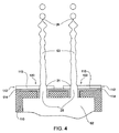
図4は、本発明の別な典型的実施例としての複数の液滴刺激用電極100を有する基板110の断面を図示している。各液滴刺激用電極100は、ノズルチャネルの排出オリフィス21を取り囲む電気コンタクト層112を有する。本発明のこの実施例では、電気コンタクト層は、絶縁層114上に形成される金属層115として形成される。絶縁層114は、基板110から金属層115を隔離する。基板110は、本実施例では導電性基板である。ノズルチャネル20及びそれらに対応する排出オリフィス21は、エッチングによって形成されて良い。エッチングは、反応性イオンエッチングであることが好ましい。好適には二酸化シリコンで構成される絶縁層114はまた、ノズルチャネル20の内側面に成膜されることで、金属層115と基板110との間を電気的にさらに隔離して良い。任意で金属層115はまた、絶縁層114の一部の上に成膜されても良い。絶縁層114は、ノズルチャネル21の内側面を覆って良い。図3を再度参照すると、ノズルチャネル20は、集積アセンブリに組み込まれた、基板110中の対応する開口部、絶縁層114及び電気コンタクト層112によって画定されて良い。図4では、電気コンタクト層112は、ジェット63が放出される排出オリフィス21を画定する。
FIG. 4 illustrates a cross-section of a
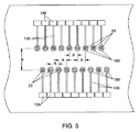
図5に図示されているように、電気コンタクト層112は、ノズルチャネル20周辺でパターニングされることで、各ノズルオリフィス100に設けられた各液滴刺激用電極100への様々な電流経路を形成して良い。電気コンタクト層135は、各独立した電流経路に形成されて良い。電気リード線は、たとえばワイヤボンディングのような手段によって電流経路に取り付けられて良い。ノズル穴を取り囲む各電極を独立して駆動するため、分離した液滴刺激駆動装置102(たとえば図3に図示されているようなもの)は、各電気リード線と接続して良い。あるいはその代わりに、液滴刺激用電極駆動装置102は、基板110に組み込まれても良い。本発明の他の実施例では、電気コンタクト層112は、パターニングされずに独立した電流経路を形成する。そのような実施例では、すべてのノズルは、単一の共通液滴刺激用駆動装置102によって駆動される。本発明のさらに別な実施例では、電気コンタクト層112は、パターニングされることで、ノズルの群を同時に駆動し、その一方で1つ以上のさらなるノズルを独立して駆動して良い。
As shown in FIG. 5, the
図5では、ノズルが2つの平行列をなすように基板上に配置されている。固定された間隔Aで、各列内のノズルチャネル20は互いに分離している。列自体は、距離Bによって互いに分離している。この配置では、2列の各々でのノズルチャネル20は、共に同一の中心間距離Aを有するが、列それ自体は、この間隔より小さな値で補正されて良い。このように構築することで、大きな間隔を有する(つまり解像度が低い)2列のノズルは、列同士を組み合わせることで実効的間隔の小さな(つまり解像度の高い)系を形成することが可能となる。2つの列の間隔B、及び所与の列内におけるノズルの間隔Aは一般的に、基板表面上の電気コンタクト135の余地をより大きくすることができるので、各異なるノズルチャネル20によって生成された液滴間での静電相互作用が減少するだけでなく、導電性経路130間での相互作用も減少する。本発明の他の実施例は、ノズルチャネル20及び液滴刺激用電極100に関して様々な配置を有して良い。
In FIG. 5, the nozzles are arranged on the substrate so as to form two parallel rows. With a fixed spacing A, the
再度図4を参照すると、電気コンタクト層112が金属層115を有するとき、ノズルチャネル20周辺の金属層115がパターニングされる前に、1つ以上のノズルチャネル20がまず基板110内でエッチングされて良い。あるいはその代わりに、金属層115はまず、基板110上でパターニングされて良い。それにより、ノズルチャネル20の意図した位置を有するパターンが登録される。マスクとしてパターニングされた金属を用いることによって、ノズルチャネル20は、基板110を貫通するようにエッチングされて良い。
Referring again to FIG. 4, when the
たとえ図4に図示された典型的実施例において電気コンタクト層112が金属層を有して良いとしても、十分な導電性を有し、かつジェットとなる所望の非導電性流体との相性がよい特性を有する他の材料が用いられても良い。MEMS製造技術が用いられるとき、液滴刺激用電極100は、導電性を含む必要な特性を有する適切な半導体基板から作製されて良い。さらに、たとえ本明細書で説明された液滴刺激用電極が、MEMS製造技術を用いることで製造されるのが好ましいとしても、MEMSだけが利用可能な技術ではない。そのようなものとして、本発明のさらに別な典型的実施例は、当技術分野で既知となっている適切な製造技術を用いることによって、適切な材料から製造される液滴刺激用電極を有して良い。
Even though the
図3、図4及び図5に図示されている本発明の典型的実施例では、電気コンタクト層112内の開口部は、排出オリフィス周辺に設けられ、かつそのオリフィスと同程度の大きさを有する。それにより、非導電性流体62が排出オリフィスからジェットされるときに電気コンタクト層が非導電性流体62と直接的に接する。電気コンタクト層112の位置は、これらの図に示された実施例に限定されない。本発明の代替的実施例は、液滴刺激用電極を有して良いが、それに限定されるわけではない。その液滴刺激用電極は、ノズルチャネル20の内側表面上に設けられた電気コンタクト層112を有する。電気コンタクト層112が非導電性ドナー流体62に近接する限り、液滴刺激用電極の設置場所は変化して良い。近接していることで、非導電性流体ジェット63を刺激することで液滴70の流れを生成するために、電荷を非導電性ドナー流体62へ移送することが可能となる。
In the exemplary embodiment of the present invention illustrated in FIGS. 3, 4 and 5, the opening in the
液滴刺激駆動装置102の影響下で、液滴刺激用電極100は一般的に、装置上の複数の位置に設けられている接地点に対してある電位で駆動する。接地点の取り得る位置の1つは、導電性基板の一部であって良い。図3に図示されているように、その導電性基板は、1つ以上のノズルチャネル20を有するノズル板を形成する。所与の刺激電位で流体ジェット63に移送される電荷量は、接地位置に依存して変化し、一般的には接地点が液滴刺激用電極から離れることで小さくなる。
Under the influence of the droplet
図3に図示された本発明の典型的な実施例では、非導電性流体ジェット63の電気流体力学的刺激により、液滴70の流れが生成される。外側半径圧力が大きくなる結果、液滴の生成が可能となる。外側半径圧力の増大は、液滴刺激用電極100によってジェット63の表面に移送される“同種の”電荷の反発に起因する。たとえ本発明のこの実施例が、非導電性流体ジェットへの電荷の移送による電気流体力学的な圧力の増大について説明しているとしても、これらの電気流体力学的圧力は、複数の機構によって発生しうる。主な機構は、電場中の自由電荷に作用するクーロン力に起因すると思われる。自由電荷は一般的に、注入されるか、又は流体と接する高電位の電極から流体へ直接移送される。非導電性流体に電気流体力学的圧力を発生させる第2の機構は、電荷分極効果及び電気歪み効果を含んで良い。たとえ非導電性流体中に電荷を確立することによるEHD圧力効果の誘起が一般的に、直接的電荷移送に起因するとしても、他のEHD機構もこれらの効果の確率に寄与しうることに留意すべきである。
In the exemplary embodiment of the present invention illustrated in FIG. 3, the flow of
非導電性流体ジェットを刺激し、反対符号を有する電荷を、ジェットの周辺に位置する様々な領域へ移送することによって液滴流を生成することもまた可能である。そのような場合では、液滴は、移送される反対符号を有する電荷の引力によって生じるピンチ効果によって生成することができる。これらの場合、液滴刺激用電極は、複数の対応する電極部分に分割されて良い。所望の極性を有する電荷でジェットの各対応する領域を帯電させる個々の液滴刺激駆動装置によって、液滴刺激用電極の各部分は駆動されて良い。そのような場合には、正味としては中性の電荷を有する液滴を生成することができる。 It is also possible to generate a droplet stream by stimulating a non-conductive fluid jet and transferring charges with opposite signs to various regions located around the jet. In such cases, the droplets can be generated by a pinch effect caused by the attractive force of the charge having the opposite sign being transported. In these cases, the droplet stimulating electrode may be divided into a plurality of corresponding electrode portions. Each portion of the droplet stimulation electrode may be driven by an individual droplet stimulation drive that charges each corresponding region of the jet with a charge having a desired polarity. In such a case, a droplet having a net neutral charge can be generated.
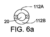
図6及び図6Aは、本発明に従った液滴刺激用電極100の別な典型的実施例を図示している。液滴刺激用電極100は、複数の導電性部分112A及び112Bを有する。この実施例では、液滴刺激用電極100は、2つの電気コンタクト層部分112A及び112Bに分割される。各層は、非導電性流体ジェット63の対向する領域と近接するように備えられている。それぞれが分離している液滴刺激駆動装置102A及び102Bは、それぞれが分離している電気コンタクト層部分112A及び112Bと電気的に接続する。液滴刺激駆動装置102A及び102Bは、2つの液滴刺激用信号72A及び72Bによって駆動する。各液滴刺激用信号はたとえば、負荷サイクルが50%の単極性方形信号の波形を有して良い。たとえ2つの信号波形が、実質的に等しい振幅及び波長を有するとしても、それぞれの極性が異なっているので、2つの信号は異なっている。
6 and 6A illustrate another exemplary embodiment of a
液滴刺激用電極72A及び72Bの影響下では、対応する電位波形が生成される。そこでは、正の電荷が非導電性流体ジェット63の一部である第1領域138に付与される一方で、負の電荷が非導電性流体ジェット63の一部である第2領域139に付与される。2つの領域は、互いに対向した位置にあるのが好ましい。非導電性流体ジェット63の対向する領域に、大きさは等しいが異なる極性の電荷が付与されることで、2つの領域を有する流体の一部での正味の電荷は、実質的にゼロになる。しかし、これらの異なる電荷の引力により、これらの領域で、非導電性流体ジェット63への電気流体力学的ピンチ効果が発生する。その結果、異なった帯電状態の領域間に位置するジェットの領域から液滴が生成される。さらに、正と負の電荷が等しく分布した状態で、中断後に液滴に移送されるので、液滴70の全体としての電荷は、実質的に中性である。生成された液滴は、実質的に等しく帯電し、かつ実質的に等しい大きさを有する。液滴刺激用電極72Aと液滴刺激用電極72Bとは両方とも、異なる電荷分布における対向する領域が、ピンチ効果を発生させる位置になるように同期する。
Under the influence of the
図3に図示された、液滴刺激用電極100の実施例によって示された刺激効果はまた、液滴刺激用電極102A及び102Bの各々に、同一波形(極性も含まれる)を有する液滴刺激用信号を同期させて供するだけで、図6に図示された電極の実施例でも実質的に再現できることに留意すべきである。
The stimulation effect illustrated by the embodiment of the
再度図3を参照すると、液滴刺激駆動装置102は、選択された電圧振幅、周期、及び時間に対する関数関係を有する電位波形(図示されていない)を発生させる。この電位波形は、非導電性流体ジェット63の様々な領域を交互に帯電させる。本明細書で説明されているように、非導電性流体ジェットの領域は、液滴刺激用電極の電気コンタクト面によって近接するジェットの領域を有して良く、このことは、電荷がその領域に移送されるか否かに依存しない。そのようなものとして、領域は、ジェットの周囲を延在する表面領域全体、又はその一部を有して良い。所望の液滴生成特性に従うと、帯電領域120は、非導電性流体ジェット63の様々な帯電部分に相当する一方で、非帯電領域125は、ジェットの非帯電部分に相当する。電位波形の適切に選択された周波数では、液滴がさらに下流となる位置でジェットから中断するまで、非導電性流体ジェット63上でこれらの帯電及び非帯電領域から生じた摂動は大きくなる。
Referring again to FIG. 3, the
非導電性流体ジェット63からの液滴の中断は、中断点26で起こる。簡明を期すため、この液滴の中断は、図3では誇張して表されているが、中断の開始は、液滴間隔の何倍ものオーダーをとって良い。典型的には、”S”が生成された液滴間の中心間距離とすると、20Sである。従来技術の連続式インクジェットプリンタで、電気流体力学的に液滴が生成される間、刺激による電荷の再分布はすぐに消失する。その理由は、導電性流体が用いられるからである。本発明では、非導電性流体に移送され、その結果として、ジェットのEHD刺激を引き起こす電荷はすぐには消失しない。図3に図示されているように、非導電性流体ジェット63が、帯電領域120の間にある領域で分離することで、液滴が生成される。液滴刺激用信号72の非限定的実施例は、50%の負荷サイクルを有する単極性方形波を含む。図3に図示されているように、刺激用信号波形72が事実上均一でかつ周期的なため、結果として生成されるそれぞれの液滴は、実質的に等しい大きさすなわち体積を有し、等しい中心間距離で互いに均等に分離している。液滴の電荷レベル及び帯電の均一性は、液滴刺激用電極100に印加される電位波形、及び液滴が中断する前における流体ジェット63を介した電荷の漏れによって制御される。本発明のこの実施例は、非導電性流体ジェットからの液滴への刺激と帯電を同時に起こす液滴刺激用手段について開示している。
The break of the droplet from the
本発明の実施例では、非導電性流体ジェットからの液滴への刺激を誘起する電荷を、生成される液滴に“固定”することが可能となる。この電荷の“固定”により、生成された液滴は様々な目的で特定可能となる。前記目的には、プリントに用いられるか否かの判断が含まれて良い。刺激された非導電性流体ジェット63から生成される選択された液滴が生成される間、刺激用信号波形の様々な部分が必ず同一とはならないように、特定化は一般的に、液滴刺激用信号72の調節を必要とする。液滴刺激用信号72の信号波形の一部は、複数の形式について変化して良い。そのような形式には、振幅、周期、パルス幅及び極性が含まれるが、それらに限定されるわけではない。液滴刺激用信号72の信号波形の一部は、様々な電荷レベル、又は様々な大きさを有する液滴70の流れの中にある選択された液滴を特定するために変化して良い。そのような液滴刺激用信号72の調節は、各異なって特定された液滴の中断時間を変化させてしまうと思われるが、本発明の実施例で説明されているような液滴刺激機構には基本的に影響を及ぼさない。
In embodiments of the present invention, it is possible to “fix” the charge that induces stimulation of the droplet from the non-conductive fluid jet to the generated droplet. This “fixing” of charge allows the generated droplets to be identified for various purposes. The purpose may include determining whether to use for printing. While the selected droplets generated from the stimulated
本発明の実施例に従った液滴刺激に適する非導電性流体は、ある抵抗値の範囲で画定されて良い。その数値範囲は、パラメータによって決定されて良い。そのパラメータは液滴が中断する時間、流体ジェットの直径及び生成される液滴間の中心間距離Sを含むが、それらに限定されるわけではない。本明細書で説明された本発明の典型的実施例に従うと、非導電性流体ジェットの液滴を刺激すること及び特定することが可能となる。その理由は、一旦電荷がジェットの様々な領域へ移送されると、電荷は、例外的に制限された容量を有することで、消失するか、又はジェットの長さ方向に移動するからである。好適には、移送された電荷は、続けて生成された液滴の中心間距離Sよりも長い距離での放電又は移動をしてはならない。移送された電荷の放電又は移動に必要な期間は、電荷が非導電性流体ジェット63の帯電領域へ移送され、それに続いてその帯電領域を中断点26での対応する液滴に組み込むのに必要な積算期間よりも長くてはならない。
Non-conductive fluids suitable for droplet stimulation according to embodiments of the present invention may be defined with a range of resistance values. The numerical range may be determined by parameters. The parameters include, but are not limited to, the time that the droplet breaks, the diameter of the fluid jet and the center-to-center distance S between the generated droplets. In accordance with the exemplary embodiments of the present invention described herein, it is possible to stimulate and identify a droplet of a non-conductive fluid jet. The reason is that once the charge is transferred to the various areas of the jet, it disappears or moves in the length of the jet, with an exceptionally limited capacity. Preferably, the transferred charge should not discharge or move at a distance longer than the center-to-center distance S of subsequently generated droplets. The period required to discharge or move the transferred charge is necessary to transfer the charge to the charged area of the
液滴の刺激に必要な、非導電性流体の抵抗値の範囲を推定するのは、移送される電荷の放電時定数TRCが、液滴の中断間隔Tb以上の長さ、つまりTRC≧Tbであることが必要となることから決定されて良い。中断間隔の期間Tbは、電気コンタクト層112から所与の帯電領域へ電荷が移送される時間から、その所与の領域から、中断点26で特定の液滴が生成される時間までの期間で計測されて良い。中断感覚期間Tbは一般的に、電気流体力学的刺激強度、流体ジェット62及び非導電性流体特性それ自体の関数として変化する。
The range of the resistance value of the non-conductive fluid required for droplet stimulation is estimated by the fact that the discharge time constant T RC of the transferred charge is longer than the droplet interruption interval T b , that is, T RC It may be determined from the fact that ≧ T b is required. Period T b of the interruption interval is the period from the
放電時定数TRCは、非導電性流体ジェットを、接地された円柱面によって囲まれた自由空間内の流体柱とするモデルを立てることで推定されて良い。流体柱の単位長さでのキャパシタンスCLは、以下の関係式から推定されて良い。 The discharge time constant T RC may be estimated by establishing a model in which a non-conductive fluid jet is a fluid column in a free space surrounded by a grounded cylindrical surface. The capacitance C L in unit length of the fluid column can be estimated from the following equation.
CL=2πε/|ln(rj/rg)|
ここで、rjは非導電性流体ジェットの半径、rgはジェットからそれを取り囲む接地面までの半径方向の距離で、εは非導電性流体ジェットを取り囲む媒体の誘電率である。
C L = 2πε / | ln (r j / r g ) |
Where r j is the radius of the non-conductive fluid jet, r g is the radial distance from the jet to the surrounding ground plane, and ε is the dielectric constant of the medium surrounding the non-conductive fluid jet.
非導電性流体ジェットが空気によって取り囲まれているとき、上述の関係式でのεの値は、ε0で表される自由空間すなわち真空での誘電率からわずかにしか異ならない。従って、ε=εair=1.0006ε0である(大気圧で、20℃)。他の種類の取り囲む媒体は、実効誘電率を、ε=εeff*ε0、εeff >1の関係式が成立するように変化させて良い。単位長さあたりのキャパシタンスを推定する目的で、キャパシタンスの下限を計算するのにε=ε0の関係が用いられて良い。上述のように、様々な接地点が、本発明によって定義される装置に設けられて良い。たとえこれらの接地点が非導電性流体ジェット63の近傍に設けられて良いにもかかわらず、距離を置いて設けられている、ジェットを取り囲む円柱面として参照接地面のモデルを立てるのは、単位長さあたりのキャパシタンスの下限、つまり放電時定数TRCの下限を供するのに用いられる。
When the non-conductive fluid jet is surrounded by air, the value of ε in the above relational expression differs only slightly from the free space represented by ε 0 , ie the dielectric constant in vacuum. Therefore, ε = ε air = 1.0006ε 0 (at atmospheric pressure, 20 ° C.). In other types of surrounding media, the effective dielectric constant may be changed so that the relational expression of ε = ε eff * ε 0 and ε eff > 1 holds. For the purpose of estimating the capacitance per unit length, the relationship ε = ε 0 may be used to calculate the lower limit of capacitance. As mentioned above, various ground points may be provided in the device defined by the present invention. Even though these grounding points may be provided in the vicinity of the
1つの液滴間距離Sの最大ジェット長での電荷の消失が起こっても良い本発明の実施例では、液滴間距離Sに等しい長さの非導電性流体ジェットの長さでの全キャパシタンスCは、関係式C=CL・Sによって推定されて良い。 In an embodiment of the invention where charge loss at a maximum jet length of one interdroplet distance S may occur, the total capacitance at the length of a non-conductive fluid jet of length equal to the interdroplet distance S C may be estimated by the relation C = C L · S.
放電時定数は、TRC=RCの関係式で与えられる。従って、本発明の実施例によって説明されたような液滴の刺激に必要な、非導電性流体の最小抵抗率ρfは、関係式ρf≧|Tb(1/2ε)(rj 2/S2)ln(rj/rg)|によって推定されて良い。ここで、変数Tb、ε、rj、rg及びSは先に定義されており、εは、大気存在下では実質的にはε0に等しい。 The discharge time constant is given by the relational expression of T RC = RC. Accordingly, the minimum resistivity ρ f of the non-conductive fluid required for droplet stimulation as described by the embodiments of the present invention is given by the relation ρ f ≧ | T b (1 / 2ε) (r j 2 / S 2 ) ln (r j / r g ) |. Here, the variable T b, ε, r j, r g and S are defined above, epsilon is substantially in the presence air equal to epsilon 0.
例として、ジェット半径rj=5μm、液滴の中心間距離S=50μmで、中断時間Tb=0.1msecでは、必要な非導電性流体の抵抗率ρfは、70MΩ-cmよりも大きな値となる。この値は、超純水の抵抗率のオーダー(約18 MΩ-cm)である。この例として挙げた抵抗率のレベルは、ほぼ下限であると見なして良い。この下限の設定により、本発明の実施例で様々な水性インクが使用できても良いし、又は使用できなくても良い。しかし、低粘性でかつ高抵抗の流体からなるインクは一般的には、推定された最小値よりも数桁も大きい抵抗率のレベルを有する。そのような流体の例には、2・1013 MΩ-cmの抵抗率を有するイソパラフィンがある。上の例で推定された抵抗率レベルは、非導電性流体ジェットから接地面までの距離を1m未満に特定したモデルに基づくため、非常に変化しにくいということに留意すべきである。本発明の実施例の実用にあたっては、非導電性流体ジェットと接地面との距離がより近接することで、非導電性流体の抵抗率の下限が可能となる。本発明の実施例で用いられた非導電性流体の抵抗率に関する実際の下限は、使用される接地面の構成に依存するが、1MΩ-cm程度と思われる。 As an example, at a jet radius r j = 5 μm, a drop center distance S = 50 μm, and an interruption time T b = 0.1 msec, the required non-conductive fluid resistivity ρ f is greater than 70 MΩ-cm. It becomes. This value is on the order of resistivity of ultrapure water (approximately 18 MΩ-cm). The resistivity level given as an example in this example may be regarded as almost the lower limit. Depending on the setting of this lower limit, various water-based inks may or may not be used in the embodiments of the present invention. However, inks composed of low viscosity and high resistance fluids typically have a resistivity level that is orders of magnitude greater than the estimated minimum. An example of such a fluid is isoparaffin having a resistivity of 2 · 10 13 MΩ-cm. It should be noted that the resistivity level estimated in the above example is very unlikely to change because it is based on a model that specifies the distance from the non-conductive fluid jet to the ground plane to be less than 1 m. In practical use of the embodiments of the present invention, the lower limit of the resistivity of the non-conductive fluid is possible because the distance between the non-conductive fluid jet and the ground plane is closer. The actual lower limit on the resistivity of the non-conductive fluid used in the examples of the present invention depends on the configuration of the ground plane used, but seems to be about 1 MΩ-cm.
本発明の実施例は、電荷を非導電性流体へ移送することで、液滴流を生成する方法について説明する。この電荷の移送はまた、ある電荷極性で液滴を特定するための電荷の移送をも含んで良い。電荷の移送はまた、ジェットを刺激することで所望の形状、大きさ又は体積の特性を有する液滴を選択的に生成するための電荷の移送をも含んで良い。非導電性流体ジェットへ移送される電荷は一般的には、導電性流体ジェットとは異なり、固定される。所与のレベルの電荷では、本発明の様々な実施例で説明された、発生する電気流体力学的刺激は一般的には、導電性流体の電気流体力学的刺激を含む従来技術よりも強い。 Embodiments of the present invention describe a method for generating a droplet stream by transferring charge to a non-conductive fluid. This charge transfer may also include charge transfer to identify the droplet with a certain charge polarity. Charge transfer may also include charge transfer to selectively produce droplets having the desired shape, size, or volume characteristics by stimulating the jet. The charge transferred to the non-conductive fluid jet is generally fixed, unlike the conductive fluid jet. At a given level of charge, the generated electrohydrodynamic stimulation described in the various embodiments of the present invention is generally stronger than the prior art involving electrohydrodynamic stimulation of conductive fluids.
液滴を生成する刺激の強度は一般的に、非導電性流体ジェット63への電気流体力学的効果によって発生する内部での半径方向の圧力に比例する。ジェット63の領域へ移送される電荷による半径方向の圧力Pは、関係式P=1/(2ε)・σ2によって推定されて良い。ここで、εは先に定義されていて、大気存在下ではε0と実質的に等しい。σは電荷密度で、関係式σ=q/(2πrj・S)によって導出されて良い。ここで、変数qは結果として生じた液滴の電荷で、変数rj及びSは先に定義されている。
The intensity of the stimulus that produces the droplet is generally proportional to the internal radial pressure generated by the electrohydrodynamic effect on the
例として、結果として生じた液滴の電荷qが100fCのオーダーで、液滴の中心間距離S=50μmで、ジェット半径rj=5μmでは、ジェットでの半径方向の圧力Pは、約230Paと推定されるものと思われる。この半径圧力値は、導電性流体ジェットを刺激するのに用いられた従来技術のEHD液滴刺激用電極によって誘起される圧力と同程度である。しかし、本発明の実施例での非導電性流体ジェットの刺激は一般的に、導電性流体ジェットでの同様の刺激よりも長い時間作用する。この作用時間の延長は、非導電性流体ジェットに移送された電荷が相対的に移動しにくくなったことに起因する。従って、本発明の実施例によって供される非導電性EHD刺激は、従来技術である導電性流体EHD刺激よりも強いものと考えられる。 As an example, if the resulting droplet charge q is on the order of 100 fC, the droplet center-to-center distance S = 50 μm and the jet radius r j = 5 μm, the radial pressure P in the jet is about 230 Pa. It seems to be estimated. This radial pressure value is comparable to the pressure induced by the prior art EHD droplet stimulating electrode used to stimulate the conductive fluid jet. However, stimulation of a non-conductive fluid jet in embodiments of the present invention generally operates for a longer time than a similar stimulus with a conductive fluid jet. This extension of the action time is due to the fact that the charge transferred to the non-conductive fluid jet becomes relatively difficult to move. Thus, the non-conductive EHD stimulation provided by the embodiments of the present invention is considered stronger than the prior art conductive fluid EHD stimulation.
本発明の様々な実施例の液滴刺激中での電荷の移送に必要な電位Vの対応する上限は、関係式V=q/Cによって推定されて良い。ここで、変数q及びCは先に定義されている。 The corresponding upper limit of potential V required for charge transfer during droplet stimulation of various embodiments of the present invention may be estimated by the relation V = q / C. Here, the variables q and C are defined previously.
電位Vは、先の例である、q=100fC、S=50μm、rj=5μmで、さらにrgを1mとした場合、430Vと推定されるものと思われる。この推定値を得るのに用いられたキャパシタンスの値は、大きな直径の接地円柱面内部での自由空間に位置する非導電性流体ジェットの単位長さあたりの導出されたキャパシタンスに基づく。従って、このキャパシタンスの値は下限と考えられ、従って上述の関係式から推定される電位は上限であると考えられる。実際には、液滴刺激用電極100に対する非導電性流体ジェット63のキャパシタンスは、電極形状の幾何学的構造及び非導電性流体ジェット63近傍の電極100の位置の関数である。実際のキャパシタンス値は一般的に、上で推定されたキャパシタンス値よりも大きい。従って、特に、電極の幾何学的構造を適切に選択し、かつ近傍の接地電極をさらに設けることで、さらにキャパシタンスを増大させるような適切な電位は、上で推定された値よりもはるかに小さくて良い。
The potential V is estimated to be 430 V when q = 100 fC, S = 50 μm, r j = 5 μm, and r g is 1 m, which is the previous example. The value of capacitance used to obtain this estimate is based on the derived capacitance per unit length of the non-conductive fluid jet located in free space within the large diameter grounded cylindrical surface. Therefore, the value of this capacitance is considered as the lower limit, and therefore the potential estimated from the above relational expression is considered as the upper limit. In practice, the capacitance of the
10 流体供給部
12 導電性流体
13 従来技術の導電性流体構造
15 従来技術の液滴刺激用電極
17 従来技術の刺激用信号駆動装置
19 刺激用信号
20 ノズルチャネル
21 排出オリフィス
22 従来技術の導電性流体ジェット
24 絶縁層
26 中断点
30 帯電電極
32 帯電電極駆動装置
34 帯電液滴
36 非帯電液滴
38 静電的偏向板
40 ガター
42 受像面
50 プリント装置
52 筐体
54 内部チャンバ
56 プリントヘッド
58 並進ユニット
60 システム制御装置
62 非導電性ドナー流体
63 非導電性流体ジェット
64 加圧された非導電性ドナー流体源
65 第1方向
66 液滴生成回路
70 液滴流
72 液滴刺激用信号
72A 液滴刺激用信号
72B 液滴刺激用信号
74 液滴分離手段
76 モーター
78 ローラー
100 液滴刺激用電極
102 液滴刺激用駆動装置
102A 液滴刺激用駆動装置
102B 液滴刺激用駆動装置
110 基板
112 導電性電気コンタクト層
112A 電気コンタクト層の一部
112B 電気コンタクト層の一部
114 絶縁層
115 金属層
120 帯電領域
120A 帯電領域
120B 帯電領域
125 非帯電領域
130 電流経路
135 電気コンタクト
137 導電性接地リング
138 非導電性流体ジェット63の一部の第1領域
139 非導電性流体ジェット63の一部の第2領域
10 Fluid supply section
12 Conductive fluid
13 Prior art conductive fluid structure
15 Prior art droplet stimulation electrodes
17 Prior art stimulation signal driver
19 Stimulation signal
20 nozzle channel
21 Discharge orifice
22 Prior art conductive fluid jets
24 Insulation layer
26 Breakpoint
30 Charging electrode
32 Charged electrode drive unit
34 Charged droplets
36 Uncharged droplets
38 Electrostatic deflector
40 gutter
42 Image receiving surface
50 printing equipment
52 Enclosure
54 Internal chamber
56 Print head
58 Translation unit
60 System controller
62 Non-conductive donor fluid
63 Non-conductive fluid jet
64 Pressurized non-conductive donor fluid source
65 First direction
66 Droplet generation circuit
70 droplet flow
72 Droplet stimulation signal
72A Droplet stimulation signal
72B Droplet stimulation signal
74 Droplet separation means
76 motor
78 Roller
100 Electrode for droplet stimulation
102 Drive device for droplet stimulation
102A droplet stimulation drive
102B Drive device for droplet stimulation
110 substrates
112 Conductive electrical contact layer
Part of 112A electrical contact layer
Part of 112B electrical contact layer
114 Insulation layer
115 metal layers
120 Charging area
120A charged area
120B charged area
125 Uncharged area
130 Current path
135 Electrical contacts
137 Conductive grounding ring
138 First region of part of
139 Second region of part of
Claims (26)
ノズルチャネル;
前記ノズルチャネルと流体のやり取りをし、かつ前記ノズルチャネルを介して前記非導電性流体のジェットを生成するように動作できる加圧源;及び
刺激用電極;
を有し、
前記刺激用電極の少なくとも一部は導電性で、かつ前記非導電性流体の一部と接触可能で、
前記刺激用電極の前記少なくとも一部の導電性部分は、前記非導電性流体ジェットの前記一部の領域へ電荷を移送するように動作でき、
前記電荷は前記非導電性流体ジェットを刺激することで非導電性流体液滴を生成する、
装置。 An apparatus for generating fluid droplets comprising:
Nozzle channel;
A pressurized source operable to communicate fluid with the nozzle channel and to generate a jet of the non-conductive fluid through the nozzle channel; and a stimulation electrode;
Have
At least a portion of the stimulation electrode is electrically conductive and in contact with a portion of the non-conductive fluid;
The at least a portion of the conductive portion of the stimulation electrode is operable to transfer charge to the portion of the non-conductive fluid jet;
The charge stimulates the non-conductive fluid jet to produce a non-conductive fluid droplet;
apparatus.
前記刺激用電極の前記少なくとも一部の導電性部分は、前記ノズルチャネルの前記排出オリフィス近傍に設けられている、
請求項1に記載の装置。 The nozzle channel has a discharge orifice;
The at least part of the conductive portion of the stimulation electrode is provided in the vicinity of the discharge orifice of the nozzle channel;
The apparatus according to claim 1.
前記刺激用電極の前記少なくとも一部の導電性部分は、前記ノズルチャネルの前記内部表面近傍に設けられている、
請求項1に記載の装置。 The nozzle channel has an internal surface;
The at least part of the conductive portion of the stimulation electrode is provided near the inner surface of the nozzle channel;
The apparatus according to claim 1.
非導電性流体ジェットを供する工程;
刺激用電極の導電性部分に電荷を供する工程;
前記電荷を、前記刺激用電極の前記導電性部分から前記非導電性流体ジェットの一部へ移送することによって、前記非導電性流体ジェットを刺激することで非導電性流体液滴を生成する工程;
を有する方法。 A method for generating fluid droplets comprising:
Providing a non-conductive fluid jet;
Providing a charge to the conductive portion of the stimulation electrode;
Generating non-conductive fluid droplets by stimulating the non-conductive fluid jet by transferring the charge from the conductive portion of the stimulation electrode to a portion of the non-conductive fluid jet. ;
Having a method.
前記非導電性流体は、関係式ρf≧|Tb(1/2ε)(rj 2/S2)ln(rj/rg)|を満たすように選択された抵抗率ρfを有し、
Tbは各流体液滴の中断時間で、
εは前記非導電性流体ジェットを取り囲む媒体の誘電率で、
rjは前記非導電性流体ジェットの半径で、
rgは前記非導電性流体ジェットから接地面への距離で、かつ
Sは連続して生成される流体液滴間の中心間距離である、
請求項11に記載の方法。 Generating the non-conductive fluid droplets by stimulating the non-conductive fluid jet comprises generating a plurality of fluid droplets;
The non-conductive fluid has a resistivity ρ f chosen to satisfy the relation ρ f ≧ | T b (1 / 2ε) (r j 2 / S 2 ) ln (r j / r g ) | And
T b is the suspension time of each fluid droplet,
ε is the dielectric constant of the medium surrounding the non-conductive fluid jet,
r j is the radius of the non-conductive fluid jet,
r g is the distance from the non-conductive fluid jet to the ground plane, and
S is the center-to-center distance between successively generated fluid droplets,
The method of claim 11.
前記少なくとも1つの導電性部分は、導電性でかつ前記非導電性流体ジェットの一部と接触可能で、
前記少なくとも1つの導電性部分は、電荷を、前記非導電性流体ジェットの前記一部へ移送し、かつ、
前記電荷は非導電性流体ジェットを刺激することで非導電性流体液滴を生成する、
電極。 A stimulating electrode for generating a fluid droplet from a non-conductive fluid jet having at least one conductive portion comprising:
The at least one conductive portion is conductive and in contact with a portion of the non-conductive fluid jet;
The at least one conductive portion transfers charge to the portion of the non-conductive fluid jet; and
The charge stimulates a non-conductive fluid jet to produce a non-conductive fluid droplet;
electrode.
前記第1部分及び前記第2部分の各々は導電性でかつ前記非導電性流体ジェットと接触可能で、
前記第1部分は、第1電荷を前記非導電性流体ジェットへ移送するように動作でき、かつ
前記第2部分は、第2電荷を前記非導電性流体ジェットへ移送するように動作できる、
請求項1に記載の装置。 The at least part of the stimulation electrode has a first portion and a second portion;
Each of the first portion and the second portion is conductive and in contact with the non-conductive fluid jet;
The first portion is operable to transfer a first charge to the non-conductive fluid jet, and the second portion is operable to transfer a second charge to the non-conductive fluid jet;
The apparatus according to claim 1.
前記刺激用電極の前記第2部分と電気的にやり取りし、第2液滴刺激用信号を受信し、かつ前記第2液滴刺激用信号に応答して前記刺激用電極の前記第2部分へ電圧電位波形を供するように動作できる、第2液滴刺激駆動装置;
をさらに有する、請求項24に記載の装置。 Electrically communicate with the first portion of the stimulation electrode, receive a first droplet stimulation signal, and respond to the first droplet stimulation signal to the first portion of the stimulation electrode A first droplet stimulation drive device operable to provide a voltage potential waveform;
Electrically communicate with the second portion of the stimulation electrode, receive a second droplet stimulation signal, and respond to the second droplet stimulation signal to the second portion of the stimulation electrode A second droplet stimulation drive device operable to provide a voltage potential waveform;
25. The apparatus of claim 24, further comprising:
Applications Claiming Priority (3)
| Application Number | Priority Date | Filing Date | Title |
|---|---|---|---|
| US61572004P | 2004-10-04 | 2004-10-04 | |
| US11/235,831 US7658478B2 (en) | 2004-10-04 | 2005-09-27 | Non-conductive fluid droplet forming apparatus and method |
| PCT/US2005/035713 WO2006041853A1 (en) | 2004-10-04 | 2005-10-03 | Non-conductive fluid droplet forming apparatus and method |
Publications (2)
| Publication Number | Publication Date |
|---|---|
| JP2008515625A true JP2008515625A (en) | 2008-05-15 |
| JP2008515625A5 JP2008515625A5 (en) | 2008-11-13 |
Family
ID=35686523
Family Applications (1)
| Application Number | Title | Priority Date | Filing Date |
|---|---|---|---|
| JP2007535758A Withdrawn JP2008515625A (en) | 2004-10-04 | 2005-10-03 | Apparatus and method for specifying non-conductive fluid droplets |
Country Status (4)
| Country | Link |
|---|---|
| US (2) | US7658478B2 (en) |
| EP (1) | EP1805019A1 (en) |
| JP (1) | JP2008515625A (en) |
| WO (1) | WO2006041853A1 (en) |
Cited By (6)
| Publication number | Priority date | Publication date | Assignee | Title |
|---|---|---|---|---|
| KR20150020272A (en) * | 2012-04-10 | 2015-02-25 | 코린시언 아프샐믹 인코포레이티드 | Spray ejector mechanisms and devices providing charge isolation and controllable droplet charge, and low dosage volume opthalmic administration |
| US10646373B2 (en) | 2011-12-12 | 2020-05-12 | Eyenovia, Inc. | Ejector mechanism, ejector device, and methods of use |
| US10839960B2 (en) | 2010-07-15 | 2020-11-17 | Eyenovia, Inc. | Ophthalmic drug delivery |
| US11260416B2 (en) | 2012-05-15 | 2022-03-01 | Eyenovia, Inc. | Ejector devices, methods, drivers, and circuits therefor |
| US11285504B2 (en) | 2012-04-20 | 2022-03-29 | Eyenovia, Inc. | Spray ejector device and methods of use |
| US11938056B2 (en) | 2017-06-10 | 2024-03-26 | Eyenovia, Inc. | Methods and devices for handling a fluid and delivering the fluid to the eye |
Families Citing this family (1)
| Publication number | Priority date | Publication date | Assignee | Title |
|---|---|---|---|---|
| WO2022031866A1 (en) * | 2020-08-04 | 2022-02-10 | The Regents Of The University Of Michigan | Combined electrohydrodynamic and aerosol printing |
Family Cites Families (23)
| Publication number | Priority date | Publication date | Assignee | Title |
|---|---|---|---|---|
| US1941001A (en) * | 1929-01-19 | 1933-12-26 | Rca Corp | Recorder |
| US3060332A (en) * | 1959-05-11 | 1962-10-23 | Research Inc | Method and apparatus for simultaneous programming and recording |
| US3596275A (en) * | 1964-03-25 | 1971-07-27 | Richard G Sweet | Fluid droplet recorder |
| US3373437A (en) * | 1964-03-25 | 1968-03-12 | Richard G. Sweet | Fluid droplet recorder with a plurality of jets |
| US3462285A (en) * | 1964-11-02 | 1969-08-19 | Phillips Petroleum Co | Electromagnetic fusion of thermoplastic printing |
| US3787881A (en) * | 1972-09-18 | 1974-01-22 | Mead Corp | Apparatus and method for bar code printing |
| US3984843A (en) * | 1974-07-01 | 1976-10-05 | International Business Machines Corporation | Recording apparatus having a semiconductor charge electrode |
| US3949410A (en) * | 1975-01-23 | 1976-04-06 | International Business Machines Corporation | Jet nozzle structure for electrohydrodynamic droplet formation and ink jet printing system therewith |
| US4070679A (en) * | 1975-06-30 | 1978-01-24 | International Business Machines Corporation | Method and apparatus for recording information on a recording surface by the use of magnetic ink |
| US4123760A (en) * | 1977-02-28 | 1978-10-31 | The Mead Corporation | Apparatus and method for jet deflection and recording |
| GB1521874A (en) * | 1977-03-01 | 1978-08-16 | Itt Creed | Printing apparatus |
| US5438739A (en) * | 1993-05-25 | 1995-08-08 | Compaq Computer Corporation | Method of making an elongated ink jet printhead |
| US5747192A (en) * | 1995-06-07 | 1998-05-05 | Avery Dennison Corporation | Single ply PSA labels for battery applications |
| US6158844A (en) * | 1996-09-13 | 2000-12-12 | Kabushiki Kaisha Toshiba | Ink-jet recording system using electrostatic force to expel ink |
| US6154226A (en) * | 1997-05-13 | 2000-11-28 | Sarnoff Corporation | Parallel print array |
| US6079821A (en) * | 1997-10-17 | 2000-06-27 | Eastman Kodak Company | Continuous ink jet printer with asymmetric heating drop deflection |
| US6312110B1 (en) * | 1999-09-28 | 2001-11-06 | Brother International Corporation | Methods and apparatus for electrohydrodynamic ejection |
| US6986566B2 (en) * | 1999-12-22 | 2006-01-17 | Eastman Kodak Company | Liquid emission device |
| US6508542B2 (en) * | 2000-12-28 | 2003-01-21 | Eastman Kodak Company | Ink drop deflection amplifier mechanism and method of increasing ink drop divergence |
| US6554410B2 (en) * | 2000-12-28 | 2003-04-29 | Eastman Kodak Company | Printhead having gas flow ink droplet separation and method of diverging ink droplets |
| US7275812B2 (en) * | 2003-01-29 | 2007-10-02 | Fujifilm Corporation | Ink jet head and recording apparatus using the same |
| US7073896B2 (en) * | 2004-02-25 | 2006-07-11 | Eastman Kodak Company | Anharmonic stimulation of inkjet drop formation |
| EP1725406A4 (en) * | 2004-03-17 | 2011-11-02 | Kodak Graphic Comm Canada Co | Method and apparatus for controlling charging of droplets |
-
2005
- 2005-09-27 US US11/235,831 patent/US7658478B2/en not_active Expired - Fee Related
- 2005-10-03 JP JP2007535758A patent/JP2008515625A/en not_active Withdrawn
- 2005-10-03 EP EP05802858A patent/EP1805019A1/en not_active Withdrawn
- 2005-10-03 WO PCT/US2005/035713 patent/WO2006041853A1/en active Application Filing
-
2010
- 2010-01-05 US US12/652,064 patent/US7992975B2/en active Active
Cited By (12)
| Publication number | Priority date | Publication date | Assignee | Title |
|---|---|---|---|---|
| US10839960B2 (en) | 2010-07-15 | 2020-11-17 | Eyenovia, Inc. | Ophthalmic drug delivery |
| US11011270B2 (en) | 2010-07-15 | 2021-05-18 | Eyenovia, Inc. | Drop generating device |
| US11398306B2 (en) | 2010-07-15 | 2022-07-26 | Eyenovia, Inc. | Ophthalmic drug delivery |
| US11839487B2 (en) | 2010-07-15 | 2023-12-12 | Eyenovia, Inc. | Ophthalmic drug delivery |
| US10646373B2 (en) | 2011-12-12 | 2020-05-12 | Eyenovia, Inc. | Ejector mechanism, ejector device, and methods of use |
| KR20150020272A (en) * | 2012-04-10 | 2015-02-25 | 코린시언 아프샐믹 인코포레이티드 | Spray ejector mechanisms and devices providing charge isolation and controllable droplet charge, and low dosage volume opthalmic administration |
| JP2018126583A (en) * | 2012-04-10 | 2018-08-16 | アイノビア,インコーポレイティド | Spray ejector mechanism, and devices providing charge isolation and controllable droplet charge, and low dosage volume ophthalmic administration |
| KR102107258B1 (en) | 2012-04-10 | 2020-05-28 | 아이노비아 인코포레이티드 | Spray ejector mechanisms and devices providing charge isolation and controllable droplet charge, and low dosage volume opthalmic administration |
| US11110000B2 (en) | 2012-04-10 | 2021-09-07 | Eyenovia, Inc. | Spray ejector mechanisms and devices providing charge isolation and controllable droplet charge, and low dosage volume ophthalmic administration |
| US11285504B2 (en) | 2012-04-20 | 2022-03-29 | Eyenovia, Inc. | Spray ejector device and methods of use |
| US11260416B2 (en) | 2012-05-15 | 2022-03-01 | Eyenovia, Inc. | Ejector devices, methods, drivers, and circuits therefor |
| US11938056B2 (en) | 2017-06-10 | 2024-03-26 | Eyenovia, Inc. | Methods and devices for handling a fluid and delivering the fluid to the eye |
Also Published As
| Publication number | Publication date |
|---|---|
| US7992975B2 (en) | 2011-08-09 |
| US7658478B2 (en) | 2010-02-09 |
| US20060092230A1 (en) | 2006-05-04 |
| US20100103228A1 (en) | 2010-04-29 |
| WO2006041853A1 (en) | 2006-04-20 |
| EP1805019A1 (en) | 2007-07-11 |
Similar Documents
| Publication | Publication Date | Title |
|---|---|---|
| JP5133691B2 (en) | Apparatus and method for identifying non-conductive fluid droplets | |
| EP2331333B1 (en) | Continuous printing system including common charge electrode | |
| US7992975B2 (en) | Non-conductive fluid droplet forming apparatus and method | |
| EP1219430A1 (en) | Printhead having gas flow ink droplet separation and method of diverging ink droplets | |
| US20040095441A1 (en) | Method and apparatus for printing ink droplets that strike print media substantially perpendicularly | |
| US8840229B2 (en) | Continuous inkjet printing system and method for producing selective deflection of droplets formed from two different break off lengths | |
| JP2002210981A (en) | Ink jet unit having amplified asymmetrically heated droplet deflection | |
| US20090231398A1 (en) | Printing by Differential Ink Jet Deflection | |
| JP4130715B2 (en) | Continuous ink jet printer with variable contact ink particle deflection. | |
| US7533965B2 (en) | Apparatus and method for electrostatically charging fluid drops | |
| EP1260369B1 (en) | A continuous ink-jet printing method and apparatus with nozzle clusters | |
| US20070126799A1 (en) | Apparatus and method for synchronously stimulating a plurality of fluid jets | |
| US5070341A (en) | Liquid stream deflection printing method and apparatus | |
| US8267504B2 (en) | Printhead including integrated stimulator/filter device | |
| EP2563594A1 (en) | Printhead stimulator/filter device printing method | |
| US10315419B2 (en) | Method for assigning communication addresses | |
| US8277035B2 (en) | Printhead including sectioned stimulator/filter device | |
| US8919930B2 (en) | Stimulator/filter device that spans printhead liquid chamber |
Legal Events
| Date | Code | Title | Description |
|---|---|---|---|
| A521 | Request for written amendment filed |
Free format text: JAPANESE INTERMEDIATE CODE: A523 Effective date: 20080926 |
|
| A621 | Written request for application examination |
Free format text: JAPANESE INTERMEDIATE CODE: A621 Effective date: 20080926 |
|
| A761 | Written withdrawal of application |
Free format text: JAPANESE INTERMEDIATE CODE: A761 Effective date: 20110608 |