JP2008509724A - Stent with extrusion coating - Google Patents
Stent with extrusion coating Download PDFInfo
- Publication number
- JP2008509724A JP2008509724A JP2007525621A JP2007525621A JP2008509724A JP 2008509724 A JP2008509724 A JP 2008509724A JP 2007525621 A JP2007525621 A JP 2007525621A JP 2007525621 A JP2007525621 A JP 2007525621A JP 2008509724 A JP2008509724 A JP 2008509724A
- Authority
- JP
- Japan
- Prior art keywords
- stent
- coating
- assembly
- stent assembly
- extruded
- Prior art date
- Legal status (The legal status is an assumption and is not a legal conclusion. Google has not performed a legal analysis and makes no representation as to the accuracy of the status listed.)
- Abandoned
Links
Images


Classifications
-
- A—HUMAN NECESSITIES
- A61—MEDICAL OR VETERINARY SCIENCE; HYGIENE
- A61F—FILTERS IMPLANTABLE INTO BLOOD VESSELS; PROSTHESES; DEVICES PROVIDING PATENCY TO, OR PREVENTING COLLAPSING OF, TUBULAR STRUCTURES OF THE BODY, e.g. STENTS; ORTHOPAEDIC, NURSING OR CONTRACEPTIVE DEVICES; FOMENTATION; TREATMENT OR PROTECTION OF EYES OR EARS; BANDAGES, DRESSINGS OR ABSORBENT PADS; FIRST-AID KITS
- A61F2/00—Filters implantable into blood vessels; Prostheses, i.e. artificial substitutes or replacements for parts of the body; Appliances for connecting them with the body; Devices providing patency to, or preventing collapsing of, tubular structures of the body, e.g. stents
- A61F2/82—Devices providing patency to, or preventing collapsing of, tubular structures of the body, e.g. stents
- A61F2/86—Stents in a form characterised by the wire-like elements; Stents in the form characterised by a net-like or mesh-like structure
- A61F2/90—Stents in a form characterised by the wire-like elements; Stents in the form characterised by a net-like or mesh-like structure characterised by a net-like or mesh-like structure
- A61F2/91—Stents in a form characterised by the wire-like elements; Stents in the form characterised by a net-like or mesh-like structure characterised by a net-like or mesh-like structure made from perforated sheet material or tubes, e.g. perforated by laser cuts or etched holes
-
- A—HUMAN NECESSITIES
- A61—MEDICAL OR VETERINARY SCIENCE; HYGIENE
- A61F—FILTERS IMPLANTABLE INTO BLOOD VESSELS; PROSTHESES; DEVICES PROVIDING PATENCY TO, OR PREVENTING COLLAPSING OF, TUBULAR STRUCTURES OF THE BODY, e.g. STENTS; ORTHOPAEDIC, NURSING OR CONTRACEPTIVE DEVICES; FOMENTATION; TREATMENT OR PROTECTION OF EYES OR EARS; BANDAGES, DRESSINGS OR ABSORBENT PADS; FIRST-AID KITS
- A61F2/00—Filters implantable into blood vessels; Prostheses, i.e. artificial substitutes or replacements for parts of the body; Appliances for connecting them with the body; Devices providing patency to, or preventing collapsing of, tubular structures of the body, e.g. stents
- A61F2/95—Instruments specially adapted for placement or removal of stents or stent-grafts
- A61F2/958—Inflatable balloons for placing stents or stent-grafts
-
- A—HUMAN NECESSITIES
- A61—MEDICAL OR VETERINARY SCIENCE; HYGIENE
- A61F—FILTERS IMPLANTABLE INTO BLOOD VESSELS; PROSTHESES; DEVICES PROVIDING PATENCY TO, OR PREVENTING COLLAPSING OF, TUBULAR STRUCTURES OF THE BODY, e.g. STENTS; ORTHOPAEDIC, NURSING OR CONTRACEPTIVE DEVICES; FOMENTATION; TREATMENT OR PROTECTION OF EYES OR EARS; BANDAGES, DRESSINGS OR ABSORBENT PADS; FIRST-AID KITS
- A61F2/00—Filters implantable into blood vessels; Prostheses, i.e. artificial substitutes or replacements for parts of the body; Appliances for connecting them with the body; Devices providing patency to, or preventing collapsing of, tubular structures of the body, e.g. stents
- A61F2/02—Prostheses implantable into the body
- A61F2/04—Hollow or tubular parts of organs, e.g. bladders, tracheae, bronchi or bile ducts
- A61F2/06—Blood vessels
- A61F2/07—Stent-grafts
- A61F2002/072—Encapsulated stents, e.g. wire or whole stent embedded in lining
-
- A—HUMAN NECESSITIES
- A61—MEDICAL OR VETERINARY SCIENCE; HYGIENE
- A61F—FILTERS IMPLANTABLE INTO BLOOD VESSELS; PROSTHESES; DEVICES PROVIDING PATENCY TO, OR PREVENTING COLLAPSING OF, TUBULAR STRUCTURES OF THE BODY, e.g. STENTS; ORTHOPAEDIC, NURSING OR CONTRACEPTIVE DEVICES; FOMENTATION; TREATMENT OR PROTECTION OF EYES OR EARS; BANDAGES, DRESSINGS OR ABSORBENT PADS; FIRST-AID KITS
- A61F2/00—Filters implantable into blood vessels; Prostheses, i.e. artificial substitutes or replacements for parts of the body; Appliances for connecting them with the body; Devices providing patency to, or preventing collapsing of, tubular structures of the body, e.g. stents
- A61F2/82—Devices providing patency to, or preventing collapsing of, tubular structures of the body, e.g. stents
- A61F2002/828—Means for connecting a plurality of stents allowing flexibility of the whole structure
Abstract
押出成形被覆を設けたステントと、その製造方法は、セル(118)を形成するステント素子(116)と、ステント(112)に配置された被覆(114)とを備える。継ぎ目のない被覆(114)がステント素子(116)とセル(118)を封入する。押出成形被覆を設けたステントは、ステント組立体を放射方向に圧縮し(工程252)、溶融重合体をステント素子およびセルに塗布し(工程254)、ステント組立体を放射方向に拡張して被覆を形成し(工程256)、ステント組立体を冷却する(工程258)ことにより製造される。次に、ステント組立体は個別のステントに分離される。収縮ダイ(154)の中でステント組立体を引伸ばすことにより圧縮が実施され、溶融重合体は押出成形装置(156)において付けられる。ステント組立体を個別のステントに分離する前、または、分離した後で、後処理を実施し被膜を付ける。
【選択図】 図1A stent provided with an extruded coating, and a method for its manufacture, includes a stent element (116) forming a cell (118) and a coating (114) disposed on the stent (112). A seamless coating (114) encloses the stent elements (116) and cells (118). A stent with an extrusion coating is coated by compressing the stent assembly radially (step 252), applying a molten polymer to the stent elements and cells (step 254), and expanding the stent assembly radially. (Step 256) and the stent assembly is cooled (step 258). The stent assembly is then separated into individual stents. Compression is performed by stretching the stent assembly in a shrink die (154) and the molten polymer is applied in an extrusion device (156). After or after the stent assembly is separated into individual stents, post processing is performed and a coating is applied.
[Selection] Figure 1
Description
本件開示の技術分野は医療用の移植片装置であり、特に、押出成形被覆を設けたステントと、その製造方法である。 The technical field of the present disclosure is a medical graft device, in particular, a stent provided with an extrusion coating and a method for manufacturing the stent.
ステントは、肉体管腔内に移植した後に放射方向に拡張して、血管その他の解剖学的管腔の一部を開存状態に保つための、略円筒状の装置である。典型的な用途の例としては、大動脈瘤を通る血液を分流させるステント補綴や、狭窄血管を拡張させる血管形成ステントなどがある。従来からステントは、薬物、その他の治療剤を搬送するように被膜と一緒に開発されてきた。 A stent is a generally cylindrical device that is radially expanded after implantation into a body lumen to keep a portion of a blood vessel or other anatomical lumen open. Examples of typical applications include a stent prosthesis that diverts blood through an aortic aneurysm and an angioplasty stent that dilates a stenotic blood vessel. Traditionally, stents have been developed with coatings to deliver drugs and other therapeutic agents.
動脈瘤は血管の複数箇所にて発生する可能性があり、腹部大動脈と胸部大動脈では特に重大である。腹部大動脈瘤は最もありふれたタイプの動脈瘤のうちの1つを代表するものであり、合衆国では年間約1万5千人が死亡している。動脈瘤が発生するのは、血管内の薄くなった点すなわち脆弱な点が拡張して、最終的に、破裂したり、凝血が生じたり、解体する潜在的可能性があるために健康上の危険の脅威となる場合である。動脈瘤は動脈で発生することが多いが、静脈でできることもある。動脈瘤形成の原因は全容が解明されたわけではないが、動脈の先天的破裂、アテローム性動脈硬化症による血管変性、血管の外傷、感染、喫煙、高血圧、その他の血管変性に至る諸原因に関連していると考えられている。腹部大動脈瘤は治療しないまま放置されると、徐々に血管が膨張し、心臓発作の原因となる血栓形成や、それ以外の血管閉鎖、血管破裂、ショックを生じ、最終的には死に至ることがある。 Aneurysms can occur at multiple locations in the blood vessel, and are particularly serious in the abdominal and thoracic aorta. Abdominal aortic aneurysms represent one of the most common types of aneurysms, with approximately 15,000 deaths per year in the United States. An aneurysm occurs because the thinned or fragile point in the blood vessel is dilated and eventually has the potential to rupture, clot, or dismantle. This is a danger threat. Aneurysms often occur in the arteries, but can also occur in veins. The cause of aneurysm formation has not been fully elucidated, but is related to various causes of congenital rupture of the artery, vascular degeneration due to atherosclerosis, vascular trauma, infection, smoking, hypertension, and other vascular degeneration It is believed that If left untreated, an abdominal aortic aneurysm gradually dilates, causing blood clots that cause a heart attack, other vascular closure, vascular rupture, shock, and ultimately death. is there.
腹部大動脈瘤は、一般に、腎臓動脈の下位の長い腹部大動脈部に局在し、回腸動脈分岐路の一方または両方の中まで延びていることが多い。動脈瘤は小さな血管膨張で始まって、漸進的に多様な予測し難い割合で拡大してゆくことがある。腹部大動脈瘤は年間に約0.5 cmから0.5 cmの平均的割合で拡大することがある。腹部大動脈瘤は、破裂のような破滅的事象が発生するまでは、静かな態様で拡大し続ける可能性がある。破裂の危険を予測するのに最もよい手段は、寸法であり、すなわち、5 cm未満の腹部大動脈瘤では破裂することは比較的まれである。しかし、約8 cmに達すると、1年以内に破裂するチャンスは75パーセントぐらいある。破裂以外のもう1つ別な腹部大動脈瘤の危険性が血栓解体である。血管が肥大すると、血液流動力の擾乱により血栓が発達して動脈瘤となる。血餅の複数砕片が最終的に緩んで搬送され、最後に、脚部、肺、または、脳で閉塞部を形成することになる。 Abdominal aortic aneurysms are typically localized in the long abdominal aorta below the renal arteries and often extend into one or both ileal arterial branches. Aneurysms begin with small vasodilation and can gradually expand at various and unpredictable rates. Abdominal aortic aneurysms may enlarge at an average rate of about 0.5 cm to 0.5 cm per year. Abdominal aortic aneurysms can continue to expand in a quiet manner until a catastrophic event such as a rupture occurs. The best means to predict the risk of rupture is size, ie, it is relatively rare to rupture in an abdominal aortic aneurysm less than 5 cm. But when it reaches about 8 cm, there is about 75 percent chance to rupture within a year. Another risk of abdominal aortic aneurysm other than rupture is thrombus disassembly. When the blood vessel is enlarged, a thrombus develops due to the disturbance of blood flow force, resulting in an aneurysm. Multiple pieces of blood clot will eventually be loosely transported and will eventually form an occlusion in the leg, lung, or brain.
腹部大動脈瘤は切開外科手術処置で最も広く治療されるが、この場合、罹患血管部はバイパス手術により人工血管移植片を使って修復される。有効な外科手術技術であると思われており、特に、通常は致命的は破裂した腹部大動脈瘤の代替の外科手術技術であると見なされてはいるが、従来の血管補綴外科手術では多数の不利益を被る。外科手術処置は複雑で、経験を積んだ医者と十分な装備のある外科手術施設を必要とする。最良の医者と最高の装備を備えてみても、このような動脈瘤を患っている患者は老齢で心臓血管の疾病やその他の疾病で弱っていることが多い。このような要因により外科手術を受けるに適格な患者の数が少なくなる。動脈瘤が破裂する前は手術適格患者でさえ、従来の動脈瘤修復術は死亡率が、通常は2%から10%と比較的高い。従来の外科手術に関連する病状としては、心筋梗塞、腎不全、虚弱、麻痺、その他の諸症状などがあった。外科手術が成功しても、開腹には数週間を要し、長い入院を必要とすることが多かった。 Abdominal aortic aneurysms are most widely treated with open surgical procedures, where the affected vessel is repaired using a vascular graft by bypass surgery. It is believed to be an effective surgical technique, especially in many cases in conventional vascular prosthetic surgery, although it is usually regarded as an alternative surgical technique for fatal ruptured abdominal aortic aneurysms Suffer disadvantages. Surgical procedures are complex and require experienced doctors and well-equipped surgical facilities. Even with the best doctors and best equipment, patients suffering from such aneurysms are often older and vulnerable to cardiovascular and other diseases. These factors reduce the number of patients eligible for surgery. Even for patients eligible for surgery before the aneurysm ruptures, conventional aneurysm repair has a relatively high mortality rate, usually 2% to 10%. Medical conditions related to conventional surgery included myocardial infarction, renal failure, weakness, paralysis, and other symptoms. Even if surgery was successful, laparotomy took weeks and often required long hospital stays.
切開外科手術に付随する欠点のうちの幾つかを克服するために、多様な血管内補綴設置技術がすでに提案されている。切開腹部外科手術を必要とせずとも、患者の合併症と回復時間は相当に低減することができる。1つの血管内腹部大動脈瘤修復技術では、大腿部動脈を通して遠隔から挿入することにより、管状の補綴が配備される。補綴は、ステントのような膨張可能な構造によって支持された合成移植片鞘部材本体から構成されている。ステントは自己拡張式またはバルーン拡張式であればよく、通例は、血管壁に補綴を固定する手段を備えている。ステント移植片補綴は血液流を大動脈の健康な部分から搬送して動脈瘤を通り、回腸動脈分岐路の一方または両方に流れ込むような分流路として作用する。補綴は動脈瘤に存在する血栓を一切放出しながら、同時に、脆弱化した血管を機械的に補強して、血栓解体と破裂の危険をそれぞれに低減する。 A variety of endovascular prosthetic placement techniques have already been proposed to overcome some of the disadvantages associated with open surgery. Without requiring open abdominal surgery, patient complications and recovery time can be significantly reduced. In one endovascular abdominal aortic aneurysm repair technique, a tubular prosthesis is deployed by remote insertion through the femoral artery. The prosthesis is composed of a synthetic graft sheath member body supported by an expandable structure such as a stent. The stent may be self-expanding or balloon expandable and typically includes a means for securing the prosthesis to the vessel wall. A stent-graft prosthesis acts as a shunt path that carries blood flow from a healthy part of the aorta, through the aneurysm, and into one or both ileal arterial branches. While the prosthesis releases any thrombus present in the aneurysm, it simultaneously mechanically reinforces the weakened blood vessels, reducing the risk of thrombus disassembly and rupture, respectively.
ステント移植片の設計は、製造と使用について複数の問題点を提示している。ステント移植片はいずれも個別に製造される。移植片繊維は、ゆっくりとした労働集約的な高額なプロセスで手作業で個々のステントに取付けられる。ステントに移植片を縫い付けるには骨が折れる。移植片をステントに熱積層するほうが迅速ではあるが、厚い移植片素材が必要となり、そのような移植片素材をステントに接着するのは上手くいかないことがある。使用にあたり、縫付け設計と積層設計の両方が欠点を有している。縫付けられたステントの針穴の穿孔が移植片素材を通して漏出を起こり得るようにすることがある。移植片素材の沈下箇所が血栓形成の部位となることもある。積層式のステント移植片も沈下することがあるが、これもまた、移植片素材に動脈瘤を形成する可能性がある。移植片素材の厚みが増しても、ステント移植片の両端部に血栓を形成することができるようにする場合があり、このような場合は、ステント移植片の高プロファイル部が血管内に突出する。 Stent graft design presents several issues for manufacturing and use. All stent grafts are manufactured separately. Graft fibers are manually attached to individual stents in a slow, labor intensive and expensive process. To sew the graft on the stent, the bone is broken. While it is quicker to heat laminate the graft to the stent, thicker graft material is required and it may not be successful to adhere such graft material to the stent. In use, both the sewing design and the laminate design have drawbacks. Perforation of the needle hole in the stitched stent may allow leakage through the graft material. The settlement site of the graft material may be the site of thrombus formation. Laminated stent grafts can also sink, which can also form an aneurysm in the graft material. Even if the thickness of the graft material increases, it may enable thrombus formation at both ends of the stent graft, in which case the high profile portion of the stent graft protrudes into the blood vessel. .
ステントは上記以外の医学的治療の各種応用例で使用され、例えば、血管内血管形成術で使われる。具体例を挙げると、バルーンカテーテル装置がPTCA(経皮経管心臓血管形成術)の最中に膨張される。狭窄症はプラークまたは血栓のような組織障害の結果である。膨張後、加圧下にあるバルーンが組織障害部に圧迫力を及ぼすことで、罹患血管の内径が増大する。増大した内部血管径は血流の改善を促進する。しかし、処置後すぐに、相当な比率の治療血管が再狭窄する。 Stents are used in various medical treatment applications other than those described above, for example, in intravascular angioplasty. As a specific example, a balloon catheter device is inflated during PTCA (percutaneous transluminal cardiovascular angioplasty). Stenosis is the result of tissue damage such as plaque or thrombus. After the inflation, the balloon under pressure exerts a compressive force on the tissue lesion, thereby increasing the inner diameter of the affected blood vessel. Increased internal vessel diameter promotes improved blood flow. However, immediately after treatment, a significant proportion of the treatment vessels restenose.
短い可撓性の円筒状ステントは、金属または多様な重合体で構成されているが、血管内に移植されると管腔寸法を維持して、再狭窄を阻止する。ステントは開存位置に管腔を指示する足場として作用する。多様な形状のステントとして、網状構造体によって輪郭を画定されている円筒状管材、複数のステントの相互接続体、同様の分節体などがある。幾つかの具体的なステントが、ボノー(Boneau)に交付された米国特許第5,292,331号(特許文献1)、グロバーマン(Globerman)に交付された米国特許第6,090,127号(特許文献2)、ヴィクター(Wiktor)に交付された米国特許第5,133,732号(特許文献3)、ポルマズ(Palmaz)に交付された米国特許第4,739,762号(特許文献4)、および、ロー(Lau)に交付された米国特許第5,421,955号(特許文献5)に開示されている。バルーン拡張式ステントは、ステントの配備時よりも小さい直径で、収縮状態のバルーンの取付けられる。ステントはまた、自己拡張式で、バルーンのような装置の機械的補佐が無くても、配備時に最終直径の大きさになることができるようにしてもよい。 Short flexible cylindrical stents are constructed of metal or various polymers, but maintain a luminal size and prevent restenosis when implanted into a blood vessel. The stent acts as a scaffold that directs the lumen to the patency position. Stents of various shapes include cylindrical tubing that is delineated by a mesh structure, interconnected multiple stents, and similar segments. Several specific stents are described in US Pat. No. 5,292,331 issued to Boneau, US Pat. No. 6,090,127 issued to Globerman, US Pat. No. 5,090,127, and Wiktor. U.S. Pat. No. 5,133,732 (Patent Document 3), U.S. Pat. No. 4,739,762 (Patent Document 4) issued to Palmaz, and U.S. Pat. No. 5,421,955 issued to Lau. (Patent Document 5). Balloon expandable stents are attached to a deflated balloon with a smaller diameter than when the stent is deployed. The stent may also be self-expanding so that it can be sized at the final diameter when deployed without the mechanical assistance of a device such as a balloon.
ステントは被膜(コーティング)と併用されて、ステントのその部位で薬剤またはそれ以外の治療薬を供出するようにしている。被膜は、薬剤またはそれ以外の治療薬を含有する液体が重合体と溶剤の混合物中に分散されたものとして付与される。液状被膜は乾燥するとステント上の固体被膜になる。液状被膜は、ステントを回転させたり振動させながらステントを浸漬し、或いは、ステントに噴霧することにより、均一な被膜を達成するように付与することができる。多様な塗布技術を組合わせて利用することもできる。 The stent is used in combination with a coating to deliver a drug or other therapeutic agent at that site of the stent. The coating is applied as a liquid containing a drug or other therapeutic agent dispersed in a polymer and solvent mixture. The liquid film becomes a solid film on the stent when dried. The liquid coating can be applied to achieve a uniform coating by immersing or spraying the stent while rotating or vibrating the stent. Various coating techniques can also be used in combination.
被膜の目的は、動脈または静脈の内壁のような、ステントに隣接している組織に薬剤を供与することである。通例は、被膜はステントワイヤ上の1層または複数層として付与される。薬剤を含有する被膜のなかには、6ヶ月以上に亘って生体内分解して薬剤を供給するものもある。 The purpose of the coating is to deliver a drug to tissue adjacent to the stent, such as the inner wall of an artery or vein. Typically, the coating is applied as one or more layers on the stent wire. Some of the coatings containing the drug supply the drug after being biodegraded over 6 months.
ソガード(Sogard)ほかに交付された米国特許第6,139,573号(特許文献6)は、拡張自在ステントの周囲に形状一致した重合体被膜を用いた被覆血管内補綴を形成する方法およびその装置を開示している。第1の重合体裏打ち材は管状ステントの内面周辺に設置され、第2の重合体裏打ち材は管状ステントの外面周辺に設置されている。第1の重合体裏打ち材と第2の重合体裏打ち材は管状ステントと形状一致して共に積層体を作り、管状ステントの内面と同延の位置でステントの開通構造の中に薄く付けられる。 US Pat. No. 6,139,573 issued to Sogard et al. Discloses a method and apparatus for forming a coated endovascular prosthesis using a conformal polymer coating around an expandable stent. ing. The first polymer backing material is placed around the inner surface of the tubular stent, and the second polymer backing material is placed around the outer surface of the tubular stent. The first polymer backing material and the second polymer backing material conform to the tubular stent to form a laminate together and are thinly applied into the stent opening structure at a location coextensive with the inner surface of the tubular stent.
バナス(Banas)ほかに交付された米国特許第6,214,039号(特許文献7)は、放射方向に拡張自在な血管内被覆ステント組立体と、その製造方法および製造装置を開示している。長軸線方向および放射方向に拡張されたポリテトラフルオロエチレンの管状移植片は1個以上の放射方向に拡張可能なステントを取り巻いて周方向に嵌合し、更に、その周面上に維持されるようにするにあたり、管状移植片がステントに抗して押圧する放射方向の反動力を利用する。 US Pat. No. 6,214,039 issued to Banas et al. Discloses a radially expandable endovascularly coated stent assembly, and a method and apparatus for manufacturing the same. A longitudinally and radially expanded polytetrafluoroethylene tubular graft is circumferentially fitted around one or more radially expandable stents and is further maintained on its circumferential surface. In doing so, it utilizes the radial reaction force that the tubular graft presses against the stent.
ダヴィラ(Davila)ほかに交付された米国特許第6,296,661号(特許文献8)、および、米国特許第6,245,100号(特許文献9)は、患者の血管内の標的部位に挿入することを目的としたステント移植片とそのようなステント移植片の製造方法を開示している。この方法は、捲縮状態と拡張状態になる自己拡張型の管状弾性外側ステントと、この外側ステントの内部に沿って挿入される管状の可撓性有孔性移植片部材と、この移植片部材の内部に沿って挿入される自己拡張式の管状弾性内側ステントとを採用している。移植片部材には前端と後端が設けられており、この両端が折り返されて、外側ステントの前端および後端に接着されて、折返し部を形成するようになっている。 U.S. Pat. No. 6,296,661 issued to Davila et al. And U.S. Pat. No. 6,245,100 describe a stent intended for insertion into a target site within a patient's blood vessel. An implant and a method for manufacturing such a stent-graft are disclosed. The method comprises a self-expanding tubular elastic outer stent in a crimped state and an expanded state, a tubular flexible perforated graft member inserted along the inside of the outer stent, and the graft member And a self-expanding tubular elastic inner stent that is inserted along the inside. The graft member is provided with a front end and a rear end, and both ends are folded and bonded to the front end and the rear end of the outer stent to form a folded portion.
ハーヴェック(Herweck)ほかに交付された米国特許第6,270,523号(特許文献10)は、保護嚢の内部に包皮された放射方向に拡張自在な支持本体部を開示している。好ましい構成では、支持体はステントであり、また、ポリテトラフルオロエチレン(PTFE)などの重合体素材の管材がステント本体部の内部を通され、そのまま折り返されステント上に重なり、折返し部を形成する。続いて、組立体が加熱され、外側層が内側層と接触して合着し、切れ目も継ぎ目も無い端部を設けた折畳み状包皮の内部にステント本体部を密着包囲する。 U.S. Pat. No. 6,270,523 issued to Herweck et al. Discloses a radially expandable support body portion encased within a protective sac. In a preferred configuration, the support is a stent, and a tube material made of a polymer material such as polytetrafluoroethylene (PTFE) is passed through the inside of the stent body and folded as it is to overlap the stent to form a folded portion. . Subsequently, the assembly is heated so that the outer layer contacts and fuses with the inner layer and tightly surrounds the stent body within a folded envelope with an end without a break or seam.
ソレム(Solem)に交付された米国特許第6,395,212号(特許文献11)は、薄膜素材の管材の中にステントを導入して上昇させた温度下に管材を曝すことで管材の直径を低減させ、管材の内部でステントが付着するように構成した被覆ステントを製造する方法を開示している。管材の両端に環部材が形成されてもよいし、また、両端が薄膜素材によって被覆されるようにしてもよい。 US Pat. No. 6,395,212, issued to Solem, reduced the diameter of the tubing by exposing the tubing to elevated temperatures by introducing a stent into the tubing of the thin film material, Disclosed is a method of manufacturing a coated stent configured to attach a stent within a tube. Ring members may be formed at both ends of the tube material, or both ends may be covered with a thin film material.
上述の欠点を克服する押出し成形された被覆を設けたステントと、その製造方法を提供するのが望まれる。 It would be desirable to provide a stent with an extruded coating that overcomes the above-mentioned drawbacks and a method for its manufacture.
本発明の一観点は、継ぎ目がなく、ステントを完全に封入する被覆の取付けが簡単である、押出成形被覆を設けたステントを提供する。 One aspect of the present invention provides a stent with an extruded coating that is seamless and easy to install a coating that completely encloses the stent.
本発明の別な観点は、被覆がステントにじかに接合された、押出成形被覆を設けたステントを提供する。 Another aspect of the present invention provides a stent with an extrusion coating wherein the coating is directly joined to the stent.
本発明の別な観点は、薄く張りつめた被膜に穿孔が存在しない、押出成形被覆を設けたステントを提供する。 Another aspect of the present invention provides a stent provided with an extruded coating in which there are no perforations in a thin, taut coating.
本発明の別な観点は、低プロファイルの押出成形被覆を設けたステントを提供する。 Another aspect of the present invention provides a stent provided with a low profile extrusion coating.
本発明の別な観点は、幾つかのステントを一度にまとめて製造することができるようにした、押出成形被覆を設けたステントを提供する。 Another aspect of the present invention provides a stent with an extrusion coating that allows several stents to be manufactured together at once.
本発明の別な観点は、煩雑で時間がかかり高額につく手作業なしで製造することができる、押出成形被覆を設けたステントを提供する。 Another aspect of the present invention provides a stent with an extrusion coating that can be manufactured without cumbersome, time consuming and expensive manual labor.
本発明の前述の特徴および利点と、それ以外の特徴および利点は、本件の好ましい実施形態の後段の詳細な説明を添付の図面と関連づけて読めば、更に明らかとなる。詳細な説明と図面は、添付の特許請求の範囲の各請求項とその均等物によって限定される本発明の範囲を制約するものというよりは、むしろ本発明の例示にすぎない。 The foregoing and other features and advantages of the present invention will become more apparent from the following detailed description of the presently preferred embodiment, read in conjunction with the accompanying drawings. The detailed description and drawings are merely illustrative of the invention rather than limiting the scope of the invention as defined by the appended claims and their equivalents.
図1は、ステントの一部が配備された状態の、本発明により製造されたステント搬送システムを例示している。ステント搬送システム100は、カテーテル102と、カテーテル102の上に配置された押出成形ステント104と、ステント104の周囲に滑動自在に配置された鞘部材106とを含んでいる。押出成形ステント104は自己拡張式であって、押出成形ステント104を鞘部材106の内部で圧縮して移植部位まで搬送し、鞘部材を後退させることで、押出成形ステント104を拡張させて移植できるように構成されている。鞘部材106を後退させながら押出成形ステント104の一部を配備したところで、押出成形ステント104の遠位端が拡張されているのが例示されている。別な実施形態では、カテーテル102はバルーンカテーテルであり、例えば、PTCA(経皮経管心臓血管形成術)で使われるバルーンカテーテルなどであればよい。押出成形ステント104はバルーンの周囲に配置されており、このバルーンを膨張させて、押出成形ステント104を拡張させることができる。バルーンは、ポリエチレン、ポリエチレンテレフタレート(PET)、ナイロン、ペバックス(Pebax:登録商標)のポリエーテルブロック共ポリアミド重合体類などのような素材から製造することができる。押出成形ステントが自己拡張型である場合は、鞘部材が押出成形ステントを拘束するのに必要となることはないが、それでも、バルーン上に押出成形ステントを保持するためには使用されてもよい。
FIG. 1 illustrates a stent delivery system made in accordance with the present invention with a portion of the stent deployed. The
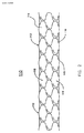
図2および図3では同じ構成要素には同じ参照番号が付与されているが、これらの図は本発明により製造された押出成形被覆を設けたステントの図とその断面図を提示している。押出成形ステント110はステント112と、ステント112上に配備された被覆114とを備えている。ステント112は、その複数のステント素子116がセル(隔室)118を形成している。被覆114がステント素子116とセル118を封入している。また別な実施形態では、追加被覆材が被覆114に付与されていてもよい。一例を挙げると、潤滑性被覆材が被覆114の外周部に付けられ、鞘部材から自己拡張型の押出成形ステントを出して配備するのを向上させることができる。また別な実施例では、治療薬を含有している1種類以上の重合体被覆材が被覆114に付けられて、押出成形ステント110が患者体内に移植された後に、治療薬が重合体被覆から溶出するようにしてもよい。
2 and 3, the same components have been given the same reference numerals, but these figures present a view of a stent with an extrusion coating made in accordance with the present invention and its cross-sectional view. The
ステント112は、当該技術分野で従来公知の、被覆材を保有することのできる移植可能な多様な補綴装置のうち、いずれであってもよい。ステント112は、収縮ダイの中で所望の直径まで弾性圧縮させることのできる弾性素材であれば、どのようなものから構成されていてもよい。通例、ステント112はニチノールなどのような形状記憶金属から製作される。ステント112は多様な方法で形成することができる。ステント112はレーザー切断またはレーザー溶接することができ、或いは、連続する構造体を形成するように一緒に巻き付けたり編組状にすることができる線条またはファイバーで構成してもよい。ステント素子116の断面部は、円形であってもよいし、楕円形であってもよいし、矩形であってもよいし、6角形であってもよいし、正方形であってもよいし、または、多角形であってもよいし、もしくは、所望に応じてそれ以外の断面形状から構成してもよい。素材次第で、ステント112は自己拡張型であってもよいし、或いは、バルーンまたは何か他の装置を利用して拡張することができるようにしてもよい。
The
被覆114は、ステント素子116を被膜するとともにセル118を充填することができる多様な被覆材のうちのいずれであってもよい。被覆114は継ぎ目がなく、ステント素子116上に在る場合よりもセル118内側に在る場合の方が薄くなってもよい。一実施例では、被覆材の厚さは1.27マイクロメートル〜7.62マイクロメートル(2000分の1インチから1000分の3インチ)の範囲となり、通例は、セル118内側の厚さが約3.81マイクロメートル(約2000分の3インチ)で、ステント素子116上の厚さが約5.08マイクロメートル(約1000分の2インチ)である。通例、被覆114はポリアミド類(ナイロン類)、ポリウレタン類、ポリエステル類、これらの各種組合せ、二元重合体類、二元重合体の共重合体類などのような重合体から構成されている。溶融重合体の中をくぐらせてステント112を押出成形して継ぎ目の無い被覆を生成することにより、被覆114がステント112に付与される。通例、被覆114は不浸透性であるけれども、浸透性があり、穿孔が設けられ、所望に応じてセルのうちの幾つかまたは全部を通して液体流通を行えるように構成してもよい。
The
図4は、本発明により製造される押出成形被覆を設けたステントの製造方法で使うためのステント組立体を例示している。ステント組立体130は複数のステント132がコネクタ134によって接合されているとともに、取付端部136を備えている。製造装備がステント組立体130の長さをうまく管理することができるかぎり、ステント組立体を作成するのに幾つのステント132が接合されてもよい。また別な実施形態では、ステント組立体130は、取付端部136を設けた1個のステント132にしてもよい。通例、ステント組立体130の周囲を廻って均一に間隔を設けて配置された少なくとも3個のコネクタ134が使用されて、軸線方向の剛性を供与するとともに、製造システムの中を円滑にステント組立体130が移動することを確実にする。取付端部136はステント組立体130を牽引部材に取付ける手段として作用し、押出成形装置と製造システムの中でステント組立体130を伸ばし成形するように構成している。
FIG. 4 illustrates a stent assembly for use in a method of manufacturing a stent with an extrusion coating made in accordance with the present invention. The
ステント組立体130は、使用されている特定の素材に適切な多数の方法によって製造される。ステント組立体130はニチノール管材のような金属管材からレーザー切断で切り離される。一実施形態では、管材は、切断されると、押出成形ステントに望ましい最終径になっている。また別な実施形態では、管材は、切断時には押出成形ステントに望ましい最終径よりも小さいが、切断された管材が拡張されてから熱硬化されて、所望の最終径にされる。
図5から図8は、本発明により製造された押出成形被覆を設けたステントを製造する方法を例示している。ステント組立体は圧縮により径が減じられ、内面と外面ともに重合体で被膜されてから、重合体が被膜を形成するように引伸ばされる。次に、ステント組立体を個々の押出成形ステントに分離する。 FIGS. 5-8 illustrate a method of making a stent with an extrusion coating made in accordance with the present invention. The stent assembly is reduced in diameter by compression and is coated with a polymer on both the inner and outer surfaces and then stretched so that the polymer forms a coating. The stent assembly is then separated into individual extruded stents.
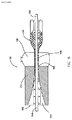
図5および図6では、同じ構成要素は同じ参照番号が付されているが、これらの図は押出成形被覆を設けたステントの製造方法を例示している。製造システムの前面部は図5では切り取られており、製造中のステント組立体の経路を露出している。図6ではステント組立体と上述の製造システムの前面部が切り取られており、芯材マンドレルを露出している。 5 and 6, the same components are labeled with the same reference numerals, but these figures illustrate a method for manufacturing a stent with an extrusion coating. The front side of the manufacturing system is cut away in FIG. 5 to expose the path of the stent assembly being manufactured. In FIG. 6, the stent assembly and the front portion of the manufacturing system described above are cut away to expose the core mandrel.
ステント組立体150は、収縮ダイ154と押出成形装置156を備えている製造システム152の中で伸ばし成形される。ステント組立体150の内部の芯材マンドレル158は製造システム152の中でステント組立体150の方向付けを行うのを助ける。ステント組立体150の取付端部160は牽引部材(図示せず)に取付けられて、この牽引部材が製造システム152の中でステント組立体150を引伸ばす。
The
ステント組立体150は収縮ダイ通路164の収縮ダイ入口162から収縮ダイ154に入る。収縮ダイ通路164は先細り状になって収縮ダイ出口166では直径が小さく、ステント組立体150が圧縮径まで低減されるようになっている。変形が主として弾性変形であり、かつ、押出成形装置156内の溶融重合体がステント組立体150の内側を外側を被覆することができるようにするのに十分なだけステント組立体150のセルが開いている限り、ステント組立体150の圧縮径はステント組立体150の内径の何分の1であれ、所望の低減径となる。一般に、圧縮されたステント組立体の直径が圧縮状態にないステント組立体の直径の約20パーセントから50パーセントになるように、収縮ダイ154がステント組立体150を圧縮させる。例えば、36 mmの非圧縮径のステントの圧縮径は約8 mmから約18 mmの間である。
The
圧縮状態のステント組立体150は、押出成形装置156内の押出成形装置通路168を通る。押出成形装置通路168は溶融重合体を貯蔵しており、この溶融重合体がステント組立体150の内側と外側を被膜し、該組立体のセルを充填する。溶融重合体はポリアミド類(ナイロン類)、プリウレタン類、ポリエステル類、これらの各種組合せなどのような好適な重合体であればよい。押出成形装置内の多様な溶融重合体に適する典型的温度の範囲は華氏200度から華氏700度の間である。
The
圧縮状態のステント組立体150は、押出成形装置156の外に出る時には、ステント組立体の初期直径まで拡張して戻るが、これは主として、ステント組立体150の弾性によるものである。ステント組立体150が拡張するにつれて、ステント組立体150のセル170の溶融重合体が伸張して薄くなる。セル170内の重合体とステント素子上の重合体がステント組立体150の被覆を形成している。通例、ステント組立体150の被覆は継ぎ目がない。薄い被覆材はステントの可撓性を増大させる。或る実施例では、被覆材の厚さは、1.27マイクロメートル〜7.62マイクロメートル(2000分の1インチから1000分の3インチ)の間にあり、通例は、セル内側の厚さが約3.81マイクロメートル(約2000分の3インチ)で、ステント素子上を覆う厚さが約5.08マイクロメートル(約1000分の2インチ)である。ステント組立体150の被覆が冷えた後、個々のステントを接合しているコネクタ位置でステント組立体150をレーザー切除または機械切除することにより、ステント組立体は個別のステントに分離される。個々のステントの切断端部は必要に応じて研磨される。
When the
ステント組立体150を個別のステントに分離する前、または、分離した後で、後処理が実施されるか、或いは、被膜が付けられる。被覆材は化学薬品または放射線で処理されて、所望の物理特性を生じるようにすることができる。例えば、熱またはガンマ線を利用して、被覆材を形成する重合体を架橋し、被覆材を硬化することができる。抗炎症剤または繁殖防止剤のような薬剤または治療薬を含有する重合体被膜をステント組立体または個別のステントに被覆の上から付けることができる。被覆材の上に被膜を付けるのは多数の方法で行えるが、例えば、噴霧、浸漬、塗装、塗布、ローラー塗装、印刷、これらの各種組合せなどがある。或る応用例については、重合体被膜は外周部のようなステントの一部に限定される。別な応用例では、異なる順序で複数の異なる治療薬を供与するのに多数の重合体被膜層を利用するのが望ましく、例えば、最外側の重合体被膜層が1種類の治療薬を供与した後に解体して、別な治療薬を含有する別な重合体被膜層を露出するのが望ましい。親水性潤滑被膜または疎水性潤滑被膜のような潤滑被膜材をステント組立体または個別のステントの被覆材または重合体被膜の上から付けて、ステントの搬送および移植中に摩擦を低減するように図ることができる。血管形成術用のステントについてのように、ステントを通る液流が望まれる場合は、被覆材はセルのうちの幾つかまたは全部に穿孔が設けられてもよい。多数の後処理技術を利用し、また、組み合わせることで、特定の応用例向きのステントを製造することができることを、当業者なら認識するだろう。
Post-treatment is performed or a coating is applied before or after the
図7は本発明により製造される押出成形被覆を設けたステントの更に別な製造方法を例示している。ステント組立体の冷却率を制御するのに、冷却槽が利用される。 FIG. 7 illustrates yet another method of manufacturing a stent provided with an extrusion coating manufactured in accordance with the present invention. A cooling bath is utilized to control the cooling rate of the stent assembly.
ステント組立体220は、収縮ダイ224、押出成形装置226、および、冷却槽228を備えている製造システム222の中で伸ばし成形される。ステント組立体220の内部の芯材マンドレル230は製造システム222の中でステント組立体220を方向付けるのを助ける。ステント組立体220は牽引部材(図示せず)に取付けられており、この牽引部材が製造システム222の中でステント組立体220を引伸ばす。
The
ステント組立体220は収縮ダイ224によって圧縮され、組立体の内側と外側が押出成形装置226内の溶融重合体で被膜される。ステント組立体220は押出成形装置226と冷却槽228の間の空隙232で伸張する。一実施形態では、この空隙232は約1 mmから10 mmである。別な実施形態では、この空隙232は省かれてもよいし、或いは、使用される特定の重合体に適合するような、また別な幅であってもよい。
The
ステント組立体220は、空隙232から出ると、冷却槽228に入る。冷却槽228は冷却液と、槽入口238を設けた容器236とを備えている。槽入口238は容器236の上端に設けた切欠きで、ステント組立体220が冷却槽228に入ると、ステント組立体が容器236の中に冷却液234を汲み戻すようになっていてもよい。冷却液234はステント組立体220の被覆材と適合性があるのであれば、どのような冷却液であってもよい。一実施形態では、冷却液は冷却水である。冷却液234の温度は、特定の重合体について所望されるように、ステント組立体220の被覆を迅速に冷却するように、または、徐々に冷却するように設定することができる。ステント組立体220の被覆材が冷えてしまうと、ステント組立体220は個別のステントに分離される。ステント組立体220または個別のステントに後処理が実施されて、更に、被膜が付けられる。
As the
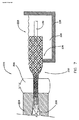
図8は、本発明により製造された押出成形被覆を設けたステントの更に別な製造方法を例示している。ステント組み立てたいの伸張を制御するのに伸張ダイが使用され、また、ステント組立体の冷却率を制御するのに冷却槽が使用される。 FIG. 8 illustrates yet another method of manufacturing a stent provided with an extrusion coating made in accordance with the present invention. A stretching die is used to control the stretching of the stent assembly and a cooling bath is used to control the cooling rate of the stent assembly.
ステント組立体180は、圧縮ダイ184と、押出成形装置186と、伸張ダイ188と、冷却槽190とを備える製造システム182の中で伸ばし成形される。ステント組立体180の内部の芯材マンドレル192は製造システム182の中でステント組立体180を方向付けるのを助ける。ステント組立体180は牽引部材(図示せず)に取付けられるが、この牽引部材が製造システム182の中でステント組立体180を引伸ばす。
The
ステント組立体180は圧縮ダイ184によって圧縮され、組立体の内側と外側は押出成形装置186の中の溶融重合体で被膜付けされる。ステント組立体180が押出成形装置186を離れる際に自由に伸張させられるのではなく、むしろ、ステント組立体180は伸張ダイ入口194の中に入ってから、伸張ダイ通路196を通りながら徐々に伸張して伸張ダイ出口198に向かう。伸張ダイ188の内部でステント組立体180を制御しながら伸張させることで、ステント組立体180のセル内の溶融重合体が伸張して薄くなっても、被覆材が裂けるのを回避することができる。制御下での伸張は、或る重合体について必要となることがある。一実施形態では、伸張ダイ出口198の直径はステントの所望の最終径である。また別な実施形態では、伸張ダイ出口198はステントの所望の最終径よりも小さく、ステント組立体180は伸張ダイ出口198を離れる際に更に拡張する。
The
伸張ダイ188を離れると、ステント組立体180は冷却槽190に入る。冷却槽190は冷却液204と、槽入口202を設けた容器200とを備えている。槽入口202は容器200の上端に設けた切欠きで、ステント組立体180が冷却槽190に入ると、ステント組立体が容器200の中に冷却液204を汲み戻すようになっていてもよい。冷却液204はステント組立体180の被覆材と適合性があるのであれば、どのような冷却液であってもよい。一実施形態では、冷却液は冷却水である。冷却液204の温度は、特定の重合体について所望されるように、ステント組立体180の被覆を迅速に冷却するように、または、徐々に冷却するように設定することができる。また別な実施形態では、冷却槽190を省いて、ステント組立体180が伸張ダイ188を出ると、遮るもののない空気中に入るようにしてもよい。ステント組立体180の被覆材が冷えてしまうと、ステント組立体180は個別のステントに分離される。ステント組立体180または個別のステントに後処理が実施され、更に、被膜が付けられる。
Upon leaving the expansion die 188, the
図9は、本発明により製造された押出成形被覆を設けたステントの製造方法のフローチャートを提示している。工程250で、ステント素子を設けてセルを形成しているステント組立体が準備される。工程252で、ステント組立体は放射方向に圧縮されるが、その手段としては、例えば、収縮ダイの中で圧縮する方法がある。工程254で、溶融重合体がステント組立体のステント素子とセルに付けられるが、その手段としては、例えば、押出成形装置を使って溶融重合体を付与する方法がある。ステント組立体は、工程256で放射方向に拡張して被覆を形成し、工程258で冷える。一実施形態では、ステント組立体は自由に拡張して初期径に戻るが、これは、ステント組立体の弾性のためである。また別な実施形態では、ステント組立体は制御された伸張率で伸張するが、その手段としては、例えば、伸張ダイの内部でステント組立体を伸張させる方法がある。また別な実施形態では、ステント組立体は、冷却槽の中で冷やすというような手段で、制御された冷却率で冷える。また別な実施形態では、ステント組立体は制御された伸張率で伸張してから、制御された冷却率で冷える。ステント組立体が冷えてしまうと、個別のステントに分離することができる。ステント組立体または個別のステントに後処理が実施され、更に、被膜が塗布される。この製造方法は使用される素材と所望される効果ごとに変更することができることが、当業者には認識することができるだろう。
FIG. 9 presents a flow chart of a method of manufacturing a stent provided with an extrusion coating made according to the present invention. At
図1から図9は本発明の特定の応用例と実施形態を例示しており、本件に提示されている開示内容または各請求項の範囲を限定するものと解釈するべきではないことに留意するのが重要となる。明細書を読んでその図面を吟味すれば、本発明の上記以外の実施形態が無数に存在し得ること、また、かかる実施形態は本件で特許請求の範囲に記載されている発明の範囲に入るものと企図されていることが、当業者には即座に明瞭となるであろう。 It should be noted that FIGS. 1-9 illustrate specific applications and embodiments of the present invention and should not be construed as limiting the disclosure or the scope of the claims presented herein. Is important. After reading the specification and examining the drawings, there may be countless other embodiments of the present invention, and such embodiments fall within the scope of the invention described in the claims herein. What is intended will be readily apparent to those skilled in the art.
本件に開示されている発明の実施形態は本件では好ましいと考えられるが、本発明の精神および範囲から逸脱せずに、多様な変更と修正を行うことができる。本発明の範囲は添付の特許請求の範囲に示されており、それらの均等物の趣意と範囲に入る変更は全て、本件に包含されるものと解釈するべきである。 While embodiments of the invention disclosed herein are considered to be preferred herein, various changes and modifications can be made without departing from the spirit and scope of the invention. The scope of the invention is indicated in the appended claims, and all changes that come within the spirit and scope of their equivalents should be construed as being encompassed by the present invention.
Claims (34)
カテーテル(102)と、
前記カテーテル(102)の上に配置された押出成形ステント(104)とを備え、押出成形ステント(104)に継ぎ目のない被覆が設けられることを特徴とする、ステント搬送システム。 A stent delivery system,
A catheter (102);
A stent delivery system comprising an extruded stent (104) disposed on the catheter (102), wherein the extruded stent (104) is provided with a seamless coating.
ステント(112)を備え、前記ステント(112)は複数のセル(118)を形成する複数のステント素子(116)を有しており、
さらに、前記ステント(112)上に配置されている被覆(114)を備え、
前記被覆(114)は前記ステント素子(116)と前記セル(118)を封入しており、前記被覆(114)は継ぎ目がないことを特徴とする、押出成形ステント。 An extruded stent,
A stent (112), the stent (112) having a plurality of stent elements (116) forming a plurality of cells (118);
And further comprising a coating (114) disposed on the stent (112),
Extruded stent, wherein the covering (114) encloses the stent element (116) and the cell (118), and the covering (114) is seamless.
ステント組立体を準備する工程(250)を含み、前記ステント組立体が複数のセルを形成する複数のステント素子を有しており、
さらに、ステント組立体を放射方向に圧縮する工程(252)と、
溶融重合体を前記ステント素子および前記セルに付ける工程(254)と、
前記ステント組立体を放射方向に拡張させて被覆を形成する工程(256)と、
前記ステント組立体を冷却する工程(258)と、
を含むことを特徴とする方法。 A method of manufacturing a stent provided with an extrusion coating comprising:
Providing a stent assembly (250), the stent assembly having a plurality of stent elements forming a plurality of cells;
Further compressing (252) the stent assembly radially;
Attaching a molten polymer to the stent element and the cell (254);
Expanding the stent assembly radially to form a coating (256);
Cooling (258) the stent assembly;
A method comprising the steps of:
ステント組立体を放射方向に圧縮する手段と、
溶融重合体をステント素子およびセルに付ける手段と、
前記ステント組立体を放射方向に拡張して被覆を形成する手段と、
を備えることを特徴とするシステム。 A system for manufacturing a stent with an extrusion coating from a stent assembly, wherein the stent assembly comprises a plurality of stent elements forming a plurality of cells;
Means for radially compressing the stent assembly;
Means for attaching the molten polymer to the stent elements and cells;
Means for radially expanding the stent assembly to form a coating;
A system comprising:
Applications Claiming Priority (2)
| Application Number | Priority Date | Filing Date | Title |
|---|---|---|---|
| US10/917,594 US20060036308A1 (en) | 2004-08-12 | 2004-08-12 | Stent with extruded covering |
| PCT/US2005/024616 WO2006019712A1 (en) | 2004-08-12 | 2005-07-12 | Stent with extruded covering |
Publications (2)
| Publication Number | Publication Date |
|---|---|
| JP2008509724A true JP2008509724A (en) | 2008-04-03 |
| JP2008509724A5 JP2008509724A5 (en) | 2008-09-04 |
Family
ID=35355330
Family Applications (1)
| Application Number | Title | Priority Date | Filing Date |
|---|---|---|---|
| JP2007525621A Abandoned JP2008509724A (en) | 2004-08-12 | 2005-07-12 | Stent with extrusion coating |
Country Status (4)
| Country | Link |
|---|---|
| US (1) | US20060036308A1 (en) |
| EP (1) | EP1802254A1 (en) |
| JP (1) | JP2008509724A (en) |
| WO (1) | WO2006019712A1 (en) |
Families Citing this family (16)
| Publication number | Priority date | Publication date | Assignee | Title |
|---|---|---|---|---|
| US8715340B2 (en) * | 2004-03-31 | 2014-05-06 | Merlin Md Pte Ltd. | Endovascular device with membrane |
| US8500751B2 (en) | 2004-03-31 | 2013-08-06 | Merlin Md Pte Ltd | Medical device |
| WO2005094725A1 (en) * | 2004-03-31 | 2005-10-13 | Merlin Md Pte Ltd | A method for treating aneurysms |
| US8267985B2 (en) * | 2005-05-25 | 2012-09-18 | Tyco Healthcare Group Lp | System and method for delivering and deploying an occluding device within a vessel |
| DE102005050386A1 (en) * | 2005-10-20 | 2007-04-26 | Campus Gmbh & Co. Kg | Temporary stent which can be deposited in a body vial |
| US8801777B2 (en) * | 2007-04-18 | 2014-08-12 | David Elmaleh | Intravascular device with netting system |
| US8597341B2 (en) * | 2006-03-06 | 2013-12-03 | David Elmaleh | Intravascular device with netting system |
| US9622888B2 (en) | 2006-11-16 | 2017-04-18 | W. L. Gore & Associates, Inc. | Stent having flexibly connected adjacent stent elements |
| US8221821B1 (en) * | 2007-11-09 | 2012-07-17 | Abbott Cardiovascular Systems Inc. | Methods of modifying ablumenal/lumenal stent coating thicknesses |
| US8926688B2 (en) | 2008-01-11 | 2015-01-06 | W. L. Gore & Assoc. Inc. | Stent having adjacent elements connected by flexible webs |
| US20100268320A1 (en) * | 2009-04-17 | 2010-10-21 | Medtronic Vascular, Inc. | Endovascular Implant Having an Integral Graft Component and Method of Manufacture |
| ES2943709T3 (en) | 2012-04-06 | 2023-06-15 | Merlin Md Pte Ltd | Devices to treat an aneurysm |
| WO2014062713A1 (en) | 2012-10-15 | 2014-04-24 | Elmaleh David R | Material structures for intravascular device |
| US9326856B2 (en) | 2013-03-14 | 2016-05-03 | St. Jude Medical, Cardiology Division, Inc. | Cuff configurations for prosthetic heart valve |
| US10299948B2 (en) | 2014-11-26 | 2019-05-28 | W. L. Gore & Associates, Inc. | Balloon expandable endoprosthesis |
| US10568752B2 (en) | 2016-05-25 | 2020-02-25 | W. L. Gore & Associates, Inc. | Controlled endoprosthesis balloon expansion |
Family Cites Families (24)
| Publication number | Priority date | Publication date | Assignee | Title |
|---|---|---|---|---|
| US4733665C2 (en) * | 1985-11-07 | 2002-01-29 | Expandable Grafts Partnership | Expandable intraluminal graft and method and apparatus for implanting an expandable intraluminal graft |
| US5133732A (en) * | 1987-10-19 | 1992-07-28 | Medtronic, Inc. | Intravascular stent |
| US5292331A (en) * | 1989-08-24 | 1994-03-08 | Applied Vascular Engineering, Inc. | Endovascular support device |
| CA2380683C (en) * | 1991-10-28 | 2006-08-08 | Advanced Cardiovascular Systems, Inc. | Expandable stents and method for making same |
| JPH09501585A (en) * | 1993-08-18 | 1997-02-18 | ダブリュ.エル.ゴア アンド アソシエイツ,インコーポレイティド | Thin and seamless porous polytetrafluoroethylene tube |
| CA2163708C (en) * | 1994-12-07 | 2007-08-07 | Robert E. Fischell | Integrated dual-function catheter system for balloon angioplasty and stent delivery |
| CA2213403C (en) * | 1995-02-22 | 2007-01-16 | Menlo Care, Inc. | Covered expanding mesh stent |
| US6053943A (en) * | 1995-12-08 | 2000-04-25 | Impra, Inc. | Endoluminal graft with integral structural support and method for making same |
| US6451047B2 (en) * | 1995-03-10 | 2002-09-17 | Impra, Inc. | Encapsulated intraluminal stent-graft and methods of making same |
| EP0850030B1 (en) * | 1995-08-24 | 2004-07-21 | Bard Peripheral Vascular, Inc. | Method of assembly of a covered endoluminal stent |
| US5776161A (en) * | 1995-10-16 | 1998-07-07 | Instent, Inc. | Medical stents, apparatus and method for making same |
| US6010529A (en) * | 1996-12-03 | 2000-01-04 | Atrium Medical Corporation | Expandable shielded vessel support |
| AU727411B2 (en) * | 1996-12-03 | 2000-12-14 | Atrium Medical Corporation | Multi-stage prosthesis |
| ATE287679T1 (en) * | 1997-03-05 | 2005-02-15 | Boston Scient Ltd | COMPLIANT MULTI-LAYER STENT DEVICE |
| US6488701B1 (en) * | 1998-03-31 | 2002-12-03 | Medtronic Ave, Inc. | Stent-graft assembly with thin-walled graft component and method of manufacture |
| US6544278B1 (en) * | 1998-11-06 | 2003-04-08 | Scimed Life Systems, Inc. | Rolling membrane stent delivery system |
| US6273911B1 (en) * | 1999-04-22 | 2001-08-14 | Advanced Cardiovascular Systems, Inc. | Variable strength stent |
| SE515231C2 (en) * | 1999-10-13 | 2001-07-02 | Jan Otto Solem | Covered stent and way to manufacture the same |
| US6296661B1 (en) * | 2000-02-01 | 2001-10-02 | Luis A. Davila | Self-expanding stent-graft |
| US6245100B1 (en) * | 2000-02-01 | 2001-06-12 | Cordis Corporation | Method for making a self-expanding stent-graft |
| US6379382B1 (en) * | 2000-03-13 | 2002-04-30 | Jun Yang | Stent having cover with drug delivery capability |
| US20030009213A1 (en) * | 2000-03-13 | 2003-01-09 | Jun Yang | Stent having cover with drug delivery capability |
| US7597775B2 (en) * | 2001-10-30 | 2009-10-06 | Boston Scientific Scimed, Inc. | Green fluoropolymer tube and endovascular prosthesis formed using same |
| US20040024448A1 (en) * | 2002-08-05 | 2004-02-05 | Chang James W. | Thermoplastic fluoropolymer-coated medical devices |
-
2004
- 2004-08-12 US US10/917,594 patent/US20060036308A1/en not_active Abandoned
-
2005
- 2005-07-12 JP JP2007525621A patent/JP2008509724A/en not_active Abandoned
- 2005-07-12 EP EP05769267A patent/EP1802254A1/en not_active Withdrawn
- 2005-07-12 WO PCT/US2005/024616 patent/WO2006019712A1/en active Application Filing
Also Published As
| Publication number | Publication date |
|---|---|
| WO2006019712A1 (en) | 2006-02-23 |
| EP1802254A1 (en) | 2007-07-04 |
| US20060036308A1 (en) | 2006-02-16 |
Similar Documents
| Publication | Publication Date | Title |
|---|---|---|
| JP2008509724A (en) | Stent with extrusion coating | |
| JP6741706B2 (en) | lattice | |
| JP2020114545A (en) | Medical device | |
| CA2566929C (en) | Endoluminal encapsulated stent and methods of manufacture and endoluminal delivery | |
| US5749880A (en) | Endoluminal encapsulated stent and methods of manufacture and endoluminal delivery | |
| CA2581855C (en) | Thin film medical device and delivery system | |
| US6143022A (en) | Stent-graft assembly with dual configuration graft component and method of manufacture | |
| EP3150176B1 (en) | Balloon-expandable/self-expanding prosthesis | |
| CA2822321C (en) | Stent | |
| EP1355591B1 (en) | Deployment system for intraluminal devices | |
| US20090043330A1 (en) | Embolic protection devices and methods | |
| US20050096725A1 (en) | Expandable stent having removable slat members | |
| JPH11347133A (en) | Endoluminal supporting assembly with end cap | |
| US8679572B2 (en) | Coated stent | |
| JP2002531219A (en) | Multi-stage expandable stent / graft | |
| WO2002022024A2 (en) | Stent with overlapping cover | |
| US9486346B2 (en) | Balloon expandable stent graft and apparatus and method for expanding a balloon expandable stent graft | |
| US20170360552A1 (en) | Expandable Stent with Constrained End | |
| JP2005342104A (en) | Stent assembly |
Legal Events
| Date | Code | Title | Description |
|---|---|---|---|
| A521 | Written amendment |
Free format text: JAPANESE INTERMEDIATE CODE: A523 Effective date: 20080711 |
|
| A621 | Written request for application examination |
Free format text: JAPANESE INTERMEDIATE CODE: A621 Effective date: 20080711 |
|
| A762 | Written abandonment of application |
Free format text: JAPANESE INTERMEDIATE CODE: A762 Effective date: 20091204 |