JP2008288598A - Controlled annealing method - Google Patents
Controlled annealing method Download PDFInfo
- Publication number
- JP2008288598A JP2008288598A JP2008132074A JP2008132074A JP2008288598A JP 2008288598 A JP2008288598 A JP 2008288598A JP 2008132074 A JP2008132074 A JP 2008132074A JP 2008132074 A JP2008132074 A JP 2008132074A JP 2008288598 A JP2008288598 A JP 2008288598A
- Authority
- JP
- Japan
- Prior art keywords
- substrate
- amount
- lamps
- annealing
- power
- Prior art date
- Legal status (The legal status is an assumption and is not a legal conclusion. Google has not performed a legal analysis and makes no representation as to the accuracy of the status listed.)
- Pending
Links
Images
Classifications
-
- H—ELECTRICITY
- H01—ELECTRIC ELEMENTS
- H01L—SEMICONDUCTOR DEVICES NOT COVERED BY CLASS H10
- H01L21/00—Processes or apparatus adapted for the manufacture or treatment of semiconductor or solid state devices or of parts thereof
- H01L21/67—Apparatus specially adapted for handling semiconductor or electric solid state devices during manufacture or treatment thereof; Apparatus specially adapted for handling wafers during manufacture or treatment of semiconductor or electric solid state devices or components ; Apparatus not specifically provided for elsewhere
- H01L21/67005—Apparatus not specifically provided for elsewhere
- H01L21/67242—Apparatus for monitoring, sorting or marking
- H01L21/67248—Temperature monitoring
-
- H—ELECTRICITY
- H01—ELECTRIC ELEMENTS
- H01L—SEMICONDUCTOR DEVICES NOT COVERED BY CLASS H10
- H01L21/00—Processes or apparatus adapted for the manufacture or treatment of semiconductor or solid state devices or of parts thereof
- H01L21/02—Manufacture or treatment of semiconductor devices or of parts thereof
- H01L21/04—Manufacture or treatment of semiconductor devices or of parts thereof the devices having at least one potential-jump barrier or surface barrier, e.g. PN junction, depletion layer or carrier concentration layer
- H01L21/18—Manufacture or treatment of semiconductor devices or of parts thereof the devices having at least one potential-jump barrier or surface barrier, e.g. PN junction, depletion layer or carrier concentration layer the devices having semiconductor bodies comprising elements of Group IV of the Periodic System or AIIIBV compounds with or without impurities, e.g. doping materials
- H01L21/30—Treatment of semiconductor bodies using processes or apparatus not provided for in groups H01L21/20 - H01L21/26
- H01L21/324—Thermal treatment for modifying the properties of semiconductor bodies, e.g. annealing, sintering
-
- H—ELECTRICITY
- H01—ELECTRIC ELEMENTS
- H01L—SEMICONDUCTOR DEVICES NOT COVERED BY CLASS H10
- H01L21/00—Processes or apparatus adapted for the manufacture or treatment of semiconductor or solid state devices or of parts thereof
- H01L21/67—Apparatus specially adapted for handling semiconductor or electric solid state devices during manufacture or treatment thereof; Apparatus specially adapted for handling wafers during manufacture or treatment of semiconductor or electric solid state devices or components ; Apparatus not specifically provided for elsewhere
- H01L21/67005—Apparatus not specifically provided for elsewhere
- H01L21/67011—Apparatus for manufacture or treatment
- H01L21/67098—Apparatus for thermal treatment
- H01L21/67115—Apparatus for thermal treatment mainly by radiation
Abstract
Description
発明の分野
[0001]本発明は、一般的に、半導体処理の分野に関し、より詳細には、半導体デバイス製造中の熱アニーリングに関する。
Field of Invention
[0001] The present invention relates generally to the field of semiconductor processing, and more particularly to thermal annealing during semiconductor device manufacturing.
関連技術の説明
[0002]急速熱処理(RTP)は、半導体製造中に基板をアニールするためのプロセスである。このプロセス中に、熱放射を使用して、制御された環境内で基板を室温より900度以上高い温度へと急速に加熱する。この温度は、プロセスにもよるが、1秒未満から数分までの時間中、維持することができる。次いで、基板を更なる処理のために室温へ冷却する。熱放射源として高輝度タングステン又はハロゲンランプが使用される。加熱されたサセプタに基板を伝導性結合すると、付加的な熱が与えられる。
Explanation of related technology
[0002] Rapid thermal processing (RTP) is a process for annealing a substrate during semiconductor manufacturing. During this process, thermal radiation is used to rapidly heat the substrate to temperatures above 900 degrees above room temperature in a controlled environment. This temperature can be maintained for times from less than 1 second to several minutes, depending on the process. The substrate is then cooled to room temperature for further processing. A high-intensity tungsten or halogen lamp is used as the heat radiation source. When the substrate is conductively coupled to the heated susceptor, additional heat is applied.
[0003]半導体製造プロセスでは、RTPが多数応用される。このような応用は、熱酸化(基板を酸素又は酸素と水素の配合中で加熱し、シリコン基板を酸化させて二酸化シリコンを生成する)、高温ソークアニール(窒素、アンモニア又は酸素のような異なるガス混合物を使用する)、低温ソークアニール(金属が堆積された基板をアニールする)、及びスパイクアニール(基板を非常に短い時間中高温に露出する必要のあるプロセスに使用される)を含む。 [0003] Many RTPs are applied in semiconductor manufacturing processes. Such applications include thermal oxidation (heating the substrate in a combination of oxygen or oxygen and hydrogen to oxidize the silicon substrate to produce silicon dioxide), high temperature soak annealing (different gases such as nitrogen, ammonia or oxygen). Use a mixture), low temperature soak anneal (anneal the substrate on which the metal is deposited), and spike anneal (used for processes where the substrate needs to be exposed to high temperatures for a very short time).
[0004]アニーリング中に、基板は、ランプアレイからの熱放射を使用して加熱される。基板は、250℃/秒までの上昇率で1000℃を越える温度に加熱することができる。次いで、ヘリウムガスのような不活性ガスのブランケットを使用して低温反射プレートに高温基板を伝導性結合することで、基板を冷却する。この強制冷却は、高速冷却率を促進し、80℃/秒の下降率を達成する。 [0004] During annealing, the substrate is heated using thermal radiation from a lamp array. The substrate can be heated to temperatures in excess of 1000 ° C. at a rate of increase of up to 250 ° C./second. The substrate is then cooled by conductively coupling the hot substrate to the cold reflector plate using a blanket of inert gas such as helium gas. This forced cooling promotes a fast cooling rate and achieves a rate of decline of 80 ° C./second.
[0005]アニーリングの目的は、基板にわたって実質的に均一の温度プロフィールを得ることである。高い上昇率及び下降率は、アニーリングプロセス中に均一性を制御するための改良された方法を必要とする。 [0005] The purpose of annealing is to obtain a substantially uniform temperature profile across the substrate. High ascent and descent rates require improved methods for controlling uniformity during the annealing process.
[0006]本発明は、一般に、急速熱アニーリングのための方法を提供する。リアルタイムの基板温度測定に基づいてチャンバー内の複数のアレイ及び/又はランプへの電力を制御することにより均一なアニーリングが行われる。一実施形態では、アニーリング方法は、チャンバー内で複数のランプの下に位置された基板の温度変化を検出し、更に、アニーリングで基板にわたり均一の温度が達成されるように、その検出された温度変化の関数として各ランプから放出される熱の量を制御することにより基板をアニーリングすることを含む。 [0006] The present invention generally provides a method for rapid thermal annealing. Uniform annealing is achieved by controlling power to multiple arrays and / or lamps in the chamber based on real-time substrate temperature measurements. In one embodiment, the annealing method detects a temperature change of a substrate located under a plurality of lamps in a chamber, and further, the detected temperature is such that a uniform temperature is achieved across the substrate by annealing. It includes annealing the substrate by controlling the amount of heat released from each lamp as a function of change.
[0007]別の実施形態では、アニーリング方法は、基板の少なくとも一部分がエッジリングに位置されるようにして、チャンバー内の複数のランプの下で少なくとも1つの非半径方向に非均一な温度を有する基板を検出し、更に、不均衡な量の熱を適当な領域に印加して基板にわたり均一な温度を達成するようにランプから放出される熱の量を制御することにより基板をアニーリングすることを含む。 [0007] In another embodiment, the annealing method has at least one non-radially non-uniform temperature under the plurality of lamps in the chamber such that at least a portion of the substrate is located in the edge ring. Detecting the substrate, and further annealing the substrate by applying an unbalanced amount of heat to the appropriate area to control the amount of heat released from the lamp to achieve a uniform temperature across the substrate. Including.
[0008]更に別の実施形態では、アニーリング方法は、基板がチャンバーへ挿入されたときに基板にわたる温度勾配を生成し、更に、アニーリングで基板にわたり均一の温度が達成されるように、チャンバー内で基板の上に位置された複数のランプの各々から放出される熱の量を温度勾配の関数として制御することにより、基板をアニーリングすることを含む。 [0008] In yet another embodiment, the annealing method generates a temperature gradient across the substrate when the substrate is inserted into the chamber, and further, a uniform temperature is achieved across the substrate upon annealing. Annealing the substrate by controlling the amount of heat released from each of the plurality of lamps positioned on the substrate as a function of the temperature gradient.
[0009]本発明の前述した特徴を詳細に理解できるように、幾つかを添付図面に例示する実施形態に関して、簡単に概要を前述した本発明について、以下により詳細に説明する。しかしながら、添付図面は、本発明の典型的な実施形態のみを例示するもので、従って、本発明の範囲をそれに限定するものではなく、本発明は、その他の均等な効果を発揮できる種々の実施形態を包含し得ることに留意されたい。 [0009] In order that the foregoing features of the invention may be more fully understood, the invention briefly described above will be described more fully hereinafter with reference to embodiments that are illustrated in the accompanying drawings. However, the attached drawings illustrate only typical embodiments of the present invention, and thus the scope of the present invention is not limited thereto, and the present invention is not limited to various implementations that can achieve other equivalent effects. Note that forms may be included.
[0014]理解を容易にするために、各図面に共通した同一の要素を指示するのに、できるだけ、同じ参照番号が使用されている。1つの実施形態の要素及び特徴は、更に詳述しなくても他の実施形態に有益に合体できることが意図される。 [0014] To facilitate understanding, identical reference numerals have been used, where possible, to designate identical elements that are common to the figures. It is contemplated that the elements and features of one embodiment may be beneficially combined with other embodiments without further elaboration.
[0015]以下に述べる本発明の実施形態は、カリフォルニア州サンタクララのアプライド・マテリアルズ社から入手できるRADIANCETMチャンバー又はVANTAGETMRadiancePlusチャンバーにおいて実施することができる。ここに述べる方法は、他の製造者からのものを含む他の適当に適応されたチャンバーにおいて実施できることも意図される。 [0015] The embodiments of the invention described below can be implemented in a RADIANCE ™ chamber or a VANTAGE ™ RadiancePlus chamber available from Applied Materials, Inc., Santa Clara, California. It is also contemplated that the methods described herein can be performed in other suitably adapted chambers, including those from other manufacturers.
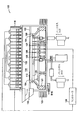
[0016]図1は、ランプ116のアレイが窓132の後方に配置された変形RTPチャンバー100内に支持された基板112を示す。一実施形態において、窓132は、石英窓でよい。別の実施形態では、窓132は、透過性材料で作られてもよい。又、一実施形態では、ランプ116は、赤外線領域の放射を放出できる。別の実施形態では、ランプ116は、近赤外線領域の放射を放出できる。更に別の実施形態では、ランプ116は、タングステンハロゲンランプで構成されてもよい。基板112は、エッジリング120に載せられ、このエッジリング120と基板112との間にはギャップ104が設けられて、エッジリング120への基板112の配置及びエッジリング120からの基板112の除去を容易にしている。コントローラ128は、パイロメータ125、126及び127から測定値を受け取り、ランプ116へ制御信号を出力する。
FIG. 1 shows a
[0017]基板112の下に配置された反射面122は、パージガス管路、リフトピン及びセンサ(図示せず)のための開口を有する。パージガスの開口の位置及び流れは、基板の温度プロフィールの制御を容易にするように構成できる。反射面122が回転しない場合には、基板非均一性の付加的な制御が与えられる。一実施形態では、反射面122を回転することができる。固定の反射面122は、局所的なガスジェット冷却及びランプの調整を容易にする。
[0017] The
[0018]或いは又、基板112は、ローター121を回転するアクチュエータ123により磁気的に回転されてもよい。アクチュエータ123は、ローター121に磁気的に結合される。一実施形態では、アクチュエータ123は、ローター121の高さを変更し及び/又はローター121の、その中心軸に対する角度方向を調整するように適応させることができる。ローター121の第1の高さは、スリットバルブ130を通して基板112を除去するために移送位置114に基板112を置く。次いで、新たな基板がアニーリングのためにローター121により位置される。カバー102は、ローター121をアニーリングプロセス中の不当な加熱から保護することができる。
Alternatively, the
[0019]別の実施形態では、ロボットブレードがチャンバー100に入り、リフトピンを上昇させて基板112をロボットブレードから持ち上げることができる。次いで、ロボットブレードを引っ込め、スリットバルブ130を閉じることができる。基板112は、リフトピンにより伝導性加熱されてもよい。次いで、リフトピンは、基板112をエッジリング120に降下させることができる。
[0019] In another embodiment, the robot blade can enter the
[0020]反射面122は、チャンバーの温度調整能力を改善するように変更することができる。反射面122は、1つ以上のパイロメータ125、126及び127のための開口をもつことができる。反射面122は、更に、ガス分配入口及び出口を含むことができる。反射面122の穴(図示せず)を通してガスを放出すると、スピード冷却を助けることができる。なぜなら、穴は、エネルギーを基板112へ反射して戻すことがないからである。反射面122における穴の設計を調整することで、熱伝達を容易にする別のメカニズムを与えることができる。又、図1に示された実施形態のような急速熱アニールシステムは、アニーリング用のレーザー、例えば、参考としてここに援用する米国特許公告第2005/0186765A1号に説明されたレーザーアニーリングシステムを備えてもよい。
[0020] The
[0021]通常、ランプ116及び反射面122は、基板に比較的均一な放射照度を発生するように設計される。この放射照度分布は、オフセット温度を慎重に変更することにより半径方向対称性と共に任意に調整することができる。熱を分散し且つ基板12の冷却のための良好な対流を得るには、ランプ116を中心からずらして配置するのが望ましい。又、より高い温度が望まれる基板112上の半径方向位置では、それに対応するランプ116の位置を、より高い電力のランプ116で構成できる一方、他の位置を、より低い電力のランプ116で構成することができ、又は、ある位置では、ランプ116を除去してもよい。増加された温度勾配が要求される場合は、反射時により細いビームを発生する反射面112を使用して、ある制御ゾーンから別の制御ゾーンへの放射の広がりを減少することができる。更に、発光ダイオード(LED)をチャンバー内に配置して、付加的な温度制御を与えることもできる。或いは又、ランプ116をLEDに置き換えてもよい。
[0021] Typically, the
[0022]又、チャンバーは、幾つかのランプ116又はランプ116の幾つかのゾーンを通して付加的な電力を放射するようにも構成できる。この付加的な電力を使用して、基板112の温度プロフィールを必要に応じて調整することができる。基板112がランプ116のヘッドに対して回転される場合には、これら構成される温度プロフィールは、主として、基板の半径に沿った非均一な温度プロフィールより成る。非均一性が望まれる半径方向位置では、対応するランプの電力を必要に応じて増加又は減少させることができる。ランプ116のパラメータの変更を使用して、異なる放射率の基板112によって生じる温度範囲縁作用の相違を補償することができる。
[0022] The chamber may also be configured to radiate additional power through
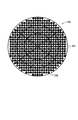
[0023]図2は、ランプ202のアレイを使用する蓋アッセンブリの底面200の部分図である。多数の個々の電球が示されているが、ランプ202のアレイは、単一の電源又は個別の電源により付勢される2個程度の電球を含むものでよい。例えば、一実施形態におけるランプ202のアレイは、第1波長分布を放出する第1電球と、第2波長分布を放出する第2電球とを含む。従って、アニーリングプロセスは、ガス流、組成、圧力及び基板温度の調整に加えて、所与のアニーリングチャンバー内における種々のランプ202での種々の照射シーケンスを定義することにより、制御することができる。
FIG. 2 is a partial view of the
[0024]ランプ202は、ランプのアレイにわたるゾーン又は領域に配列することができる。ゾーンは、基板の中心から半径方向へ延びてもよいし、又は基板の直径にわたる区分に配列されてもよい。例えば、ゾーンは、基板の周囲へより多くの熱を向けるか、或いは基板が回転するときに基板を露出させるための異なるスペクトルをもつ電球を設けるように選択されてもよい。電球の配置は、基板が回転されないときには、得られる基板特性に著しく影響を及ぼし得る。
[0024] The
[0025]ランプ202のアレイは、1つ、2つ又はそれ以上の異なる形式の個々の電球を選択してランプ202のアレイ内に配列することにより、特定のUVスペクトル分布要件を満足するように設計することができる。例えば、電球は、低圧力Hg、中圧力Hg及び高圧力Hgから選択することができる。
[0025] The array of
[0026]ランプ202のアレイは、UV発光ダイオードのような高効率の電球を利用することができる。マイクロ波又はパルス電源により付勢されるUV光源は、変換効率が5%であり、これに比して、10W−100Wのような低電力電球は、ランプ202のアレイにおいて、約20%の変換効率を発揮することができる。マイクロ波電源では、全エネルギーの95%が熱に変換されてエネルギーを浪費すると共に、余計な冷却要求を余儀なくされ、5%のエネルギーしかUV放射に変換されない。低電力電球は、冷却要求が低いので、ランプ202のアレイを基板に接近配置し(例えば、1乃至6インチ)、反射UV光及びエネルギーロスを減少することができる。
[0026] The array of
[0027]更に、蓋アッセンブリの底面200は、ランプ202のアレイ内にインターリーブされた複数のガス出口204を含むことができる。従って、チャンバー内のプロセス領域へ上から処理ガスを導入することができる。参考としてここに援用する米国特許公告第2006/0251827A1号から付加的な詳細情報を得ることができる。
[0027] In addition, the
[0028]図1を再び参照すれば、処理中に、ランプ116は、基板112を上述したように高い温度に加熱することができる。アニーリングは、基板112を加熱するだけでなく、チャンバー100の処理エリアからランプ116を分離する石英窓132を含む種々のチャンバーコンポーネントも加熱する。チャンバー100に入る基板112は、最初、室温のことがある。基板112がスロットバルブ130を通してチャンバー100に入るときには、基板112が石英窓132に接近するために、基板112の先縁が加熱を開始できる。従って、基板112がチャンバー100に入るときには、基板112の先縁が、プロセスチャンバー100の外部にある基板112の後縁に比して、室温より高い温度になり得る。それ故、基板112がチャンバー100に入るときには、基板112にわたり温度勾配が発生する。基板112がプロセスチャンバー100内に完全に収容されるときまでに、基板112の先縁は、基板112の後縁に比して、チャンバー100の加熱されたコンポーネントに、より長い時間、曝されるので、基板112は、基板112にわたって均一な温度にならないことがある。
[0028] Referring again to FIG. 1, during processing, the
[0029]更に、基板112がチャンバー100に挿入されたときには、基板112がエッジリング120に載せられる。エッジリング120は、手前のアニーリングプロセスで加熱されているので、エッジリング120は、手前のアニーリングプロセスからある程度の熱を保有して、基板112より高い温度になっており、基板112を伝導性加熱することがある。エッジリング120に接触する基板112の部分は、エッジリング120に接触しない基板112の部分より高い温度に伝導性加熱され得る。それ故、基板112の縁から基板112の中心へと温度勾配が生じ得る。発生し得る別の問題として、基板112がエッジリング120と重畳するところでは大きな熱質量が加熱される。重畳の大きい(即ち、完全に中心に置かなかったことによる)エリアは、同じ半径で重畳が小さいエリアに対して、温度上昇中の加熱率が小さくなり得る。純粋な半径方向制御ゾーンにより温度の非均一性が軽減されることはない。リフトピンで基板112を受ける実施形態では、個々のランプ116の電力の不一致及び/又は基板112の非回転のために、基板112にわたって温度非均一性が生じることがある。
Further, when the
[0030]基板112がエッジリング120に配置されるときに、基板112は、エッジリング120の完全に中心に来ないことがある。エッジリング120と基板112の縁との間のギャップのために、基板112は、エッジリング120において若干中心をずれることがある。それに加えて又はそれとは別に、ロボットは、基板112を全く同じ位置に繰り返し配置できないことがある。従って、エッジリング120に載せられる基板112の部分は、基板112の中心から均一な半径方向距離にならないことがある。それ故、基板112の縁から基板112の中心へ温度勾配が生じるだけでなく、基板112の縁から基板112の中心への温度勾配が基板112の周りの各角度位置において変化することもある。
[0030] When the
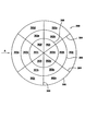
[0031]基板112にわたる温度勾配を補償するために、ランプを複数のゾーン(302a−k、302m、302n及び302p−302t)に分割することができ、各ゾーンは、1つ以上のランプを含む。図3は、ランプが除去された図2の蓋アッセンブリの底面を示す部分図である。各ゾーン(302a−k、302m、302n及び302p−302t)は、境界304、306により画成することができる。各ゾーン(302a−k、302m、302n及び302p−302t)内のランプは、より大きな制御を与えるように集合的に付勢されてもよいし、各ゾーン(302a−k、302m、302n及び302p−302t)内で個々に付勢されてもよい。ゾーン(302a−k、302m、302n及び302p−302t)及び/又は個々のランプに印加される電力は、パイロメータにより与えられるリアルタイムフィードバックに基づいて調整することができる。更に、アニーリング中に基板が回転するときには、種々のゾーン(302a−k、302m、302n及び302p−302t)及び/又は個々のランプに印加される電力は、任意の瞬間にゾーン(302a−k、302m、302n及び302p−302t)及び/又はランプの下に存在する基板の部分の温度を補償するように調整することができる。パイロメータからのリアルタイムフィードバックは、ゾーン(302a−k、302m、302n及び302p−302t)及び/又は個々のランプに与えられる電力を連続的に調整できるように、電力のリアルタイム制御を許す。この制御は、ゾーン(302a−k、302m、302n及び302p−302t)及び/又は個々のランプに、より低い電力又はより高い電力を与えるか、或いは電力を与えないようにすることを含んでもよい。温度勾配がもはや存在しなくなると、全てのゾーン(302a−k、302m、302n及び302p−302t)及び/又は全ての個々のランプに、同じレベルの電力を与えることができる。
[0031] To compensate for the temperature gradient across the
[0032]図3に示すように、基板は、矢印「A」で示された方向に蓋アッセンブリの下でチャンバーに入ることができる。基板がチャンバー内に位置されると、パイロメータ(図1を参照)は、種々の所定の位置で基板の温度を測定することができる。各ゾーン(302a−k、302m、302n及び302p−302t)に印加される電力は、次いで、種々の所定の位置の測定温度に基づいてセットすることができる。例えば、基板の先縁は基板の後縁に比して高い温度になり得るので、基板の後縁に対応するゾーン302aには、基板の先縁に対応するゾーン302jに比して高い電力を与えることができる。他のゾーン(302b−i、302k、302m、302n及び302p−302t)も、温度測定に基づいて調整することができる。ゾーン(302a−k、302m、302n及び302p−302t)及び/又は個々のランプへの電力は、基板の回転と同期されてもよい。ゾーン(302a−k、302m、302n及び302p−302t)及び/又は個々のランプに印加される電力を制御できることで、基板の中心から同じ半径方向距離における変動を含む基板の温度変動が補償される。
[0032] As shown in FIG. 3, the substrate may enter the chamber under the lid assembly in the direction indicated by arrow "A". Once the substrate is positioned in the chamber, a pyrometer (see FIG. 1) can measure the temperature of the substrate at various predetermined locations. The power applied to each zone (302a-k, 302m, 302n and 302p-302t) can then be set based on the measured temperatures at various predetermined locations. For example, since the leading edge of the substrate can be at a higher temperature than the trailing edge of the substrate, the
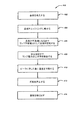
[0033]図4は、本発明の一実施形態によるアニーリングプロセスを示すフローチャート400である。ステップ402において、基板がチャンバーに挿入される。基板が挿入されるときに、基板の先縁の加熱を開始することができる。ステップ404において、基板がエッジリングに配置される。上述したように、基板は、エッジリングの完全に中心に配置されることもあるし、又は基板は、エッジリングの中心を若干ずれて配置されることもある。
[0033] FIG. 4 is a
[0034]ステップ406において、基板は回転を開始する。基板が回転すると、ステップ408において、ランプへの電力の上昇率を基板にわたる複数の位置に対するリアルタイム温度フィードバックに基づいて調整することができる。基板は、最初に、基板が熱から不透過になるまで低い電力でアニールされる。その後、アニーリング温度を所定の温度まで上昇することができる。アニーリングに続いて、温度を降下させ(ステップ410)、回転を停止することができる(ステップ412)。次いで、基板を取り出すことができる(ステップ414)。
[0034] In
[0035]ランプのゾーン及び/又は個々のランプを、基板にわたる温度測定のリアルタイムフィードバックに基づいて個々に制御することにより、基板の均一なアニーリングが可能となる。 [0035] By individually controlling the lamp zones and / or individual lamps based on real-time feedback of temperature measurements across the substrate, uniform annealing of the substrate is possible.
[0036]以上、本発明の実施形態を説明したが、本発明の基本的な範囲から逸脱せずに他の実施形態及び更に別の実施形態を案出することができ、従って、本発明の範囲は、特許請求の範囲によって決定されるものとする。 [0036] While embodiments of the invention have been described above, other and further embodiments can be devised without departing from the basic scope of the invention, and thus The scope shall be determined by the claims.
100…RTPチャンバー、102…カバー、104…ギャップ、112…基板、114…移送位置、116…ランプ、120…エッジリング、121…ローター、122…反射面、123…アクチュエータ、125、126、127…パイロメータ、128…コントローラ、130…スリットバルブ、132…窓、200…底面、202…ランプ、204…ガス出口、302a−k、302m、302n、302p−302t…ゾーン、304、306…境界
DESCRIPTION OF
Claims (15)
アニーリングで上記基板にわたり均一の温度が達成されるように、上記検出された温度変化の関数として各ランプから放出される熱の量を制御することにより、上記基板をアニーリングするステップと、
を備えたアニーリング方法。 Detecting a temperature change of a substrate positioned under a plurality of lamps in a chamber;
Annealing the substrate by controlling the amount of heat released from each lamp as a function of the detected temperature change so that a uniform temperature is achieved across the substrate upon annealing;
Annealing method with
上記検出ステップは、上記基板が回転するときに上記基板にわたる複数の位置で温度を検出することを含み、
上記アニーリングステップは、各ランプから放出される熱の量の制御を、上記検出された温度の関数として上記基板の回転と同期させることを含み、上記放出される熱の量の制御は、1つ以上のランプへの電力の量を減少することと、次のうちの少なくとも1つ、即ち
1つ以上の他のランプへの電力の量を増加すること、及び
1つ以上の他のランプに印加される電力の量を維持すること、
の1つを含む、請求項1に記載の方法。 Further comprising rotating the substrate during the annealing;
The detecting step includes detecting temperatures at a plurality of positions across the substrate as the substrate rotates;
The annealing step includes synchronizing the control of the amount of heat released from each lamp with the rotation of the substrate as a function of the detected temperature, wherein the control of the amount of heat released is one. Reducing the amount of power to these lamps, increasing the amount of power to at least one of the following: one or more other lamps, and applying to one or more other lamps Maintaining the amount of power being played,
The method of claim 1, comprising one of:
1つ以上の他のランプへの電力の量を増加すること、及び
1つ以上の他のランプに印加される電力の量を維持すること、
の1つを含む、請求項1に記載の方法。 The control of the amount of heat released reduces the amount of power to one or more lamps and increases the amount of power to at least one of the following: one or more other lamps. And maintaining the amount of power applied to one or more other lamps,
The method of claim 1, comprising one of:
不均衡な量の熱を適当な領域に印加して上記基板にわたり均一な温度を達成するようにランプから放出される熱の量を制御することにより上記基板をアニーリングするステップと、
を備えたアニーリング方法。 Detecting at least one non-radially non-uniform temperature substrate under the plurality of lamps in the chamber such that at least a portion of the substrate is located on the edge ring;
Annealing the substrate by applying an unbalanced amount of heat to the appropriate area to control the amount of heat released from the lamp to achieve a uniform temperature across the substrate;
Annealing method with
上記検出ステップは、上記基板が回転するときに上記基板にわたる複数の位置で温度を検出することを含み、
上記アニーリングするステップは、各ランプから放出される熱の量の制御を、上記検出された温度の関数として上記基板の回転と同期させることを含み、上記放出される熱の量の制御は、1つ以上のランプへの電力の量を減少することと、次のうちの少なくとも1つ、即ち
1つ以上の他のランプへの電力の量を増加すること、及び
1つ以上の他のランプに印加される電力の量を維持すること、
の1つを含む、請求項7に記載の方法。 Further comprising rotating the substrate during the annealing;
The detecting step includes detecting temperatures at a plurality of positions across the substrate as the substrate rotates;
The annealing step includes synchronizing the control of the amount of heat released from each lamp with the rotation of the substrate as a function of the detected temperature, the control of the amount of heat released being 1 Reducing the amount of power to one or more lamps, increasing the amount of power to at least one of the following: one or more other lamps, and one or more other lamps Maintaining the amount of power applied,
The method of claim 7, comprising one of:
アニーリング中に上記基板を回転することを含み、温度変化の上記検出は、この回転中に行なわれ、更に、
各ランプから放出される熱の量の制御を、上記検出された温度の関数として上記基板の回転と同期させることを含み、
上記アニーリングは、上記基板の中心から等しい半径方向距離の複数の位置に異なる量の熱を付与することを含む、請求項7に記載の方法。 Detecting temperature changes at a plurality of locations of the substrate at equal radial distances from the center of the substrate, the step further comprising:
Rotating the substrate during annealing, wherein the detection of the temperature change is performed during the rotation;
Synchronizing the control of the amount of heat released from each lamp with the rotation of the substrate as a function of the detected temperature;
The method of claim 7, wherein the annealing includes applying different amounts of heat to a plurality of locations at equal radial distances from the center of the substrate.
1つ以上の他のランプへの電力の量を増加すること、及び
1つ以上の他のランプに印加される電力の量を維持すること、
の1つを含む、請求項7に記載の方法。 The control of the amount of heat released reduces the amount of power to one or more lamps and increases the amount of power to at least one of the following: one or more other lamps. And maintaining the amount of power applied to one or more other lamps,
The method of claim 7, comprising one of:
アニーリングで上記基板にわたり均一の温度が達成されるように、上記チャンバー内で上記基板の上に位置された複数のランプの各々から放出される熱の量を上記温度勾配の関数として制御することにより、上記基板をアニーリングするステップと、
を備えたアニーリング方法。 Generating a temperature gradient across the substrate when the substrate is inserted into the chamber;
By controlling the amount of heat released from each of a plurality of lamps positioned on the substrate in the chamber as a function of the temperature gradient so that a uniform temperature is achieved across the substrate by annealing. Annealing the substrate;
Annealing method with
上記基板が回転するときに上記基板にわたる複数の位置で温度を検出するステップと、
各ランプから放出される熱の量の制御を、上記検出された温度の関数として上記基板の回転と同期させるステップと、
を更に備え、上記放出される熱の量の制御は、1つ以上のランプへの電力の量を減少することと、次のうちの少なくとも1つ、即ち
1つ以上の他のランプへの電力の量を増加すること、及び
1つ以上の他のランプに印加される電力の量を維持すること、
の1つを含む、請求項12に記載の方法。 Rotating the substrate during the annealing;
Detecting temperatures at a plurality of locations across the substrate as the substrate rotates;
Synchronizing the control of the amount of heat released from each lamp with the rotation of the substrate as a function of the detected temperature;
And the control of the amount of heat dissipated reduces the amount of power to one or more lamps and at least one of the following: power to one or more other lamps Increasing the amount of power, and maintaining the amount of power applied to one or more other lamps,
The method of claim 12, comprising one of:
The method of claim 12, wherein two or more of the plurality of lamps are coupled together and controlled simultaneously.
Applications Claiming Priority (1)
| Application Number | Priority Date | Filing Date | Title |
|---|---|---|---|
| US11/751,027 US20080090309A1 (en) | 2003-10-27 | 2007-05-20 | Controlled annealing method |
Publications (2)
| Publication Number | Publication Date |
|---|---|
| JP2008288598A true JP2008288598A (en) | 2008-11-27 |
| JP2008288598A5 JP2008288598A5 (en) | 2011-07-07 |
Family
ID=39493369
Family Applications (1)
| Application Number | Title | Priority Date | Filing Date |
|---|---|---|---|
| JP2008132074A Pending JP2008288598A (en) | 2007-05-20 | 2008-05-20 | Controlled annealing method |
Country Status (6)
| Country | Link |
|---|---|
| US (1) | US20080090309A1 (en) |
| EP (1) | EP1995766A3 (en) |
| JP (1) | JP2008288598A (en) |
| KR (1) | KR100976649B1 (en) |
| CN (1) | CN101431005B (en) |
| TW (1) | TWI455208B (en) |
Cited By (2)
| Publication number | Priority date | Publication date | Assignee | Title |
|---|---|---|---|---|
| JP2013520801A (en) * | 2010-02-19 | 2013-06-06 | アプライド マテリアルズ インコーポレイテッド | High efficiency / high accuracy heater driver |
| WO2016014174A1 (en) * | 2014-07-25 | 2016-01-28 | Applied Materials, Inc. | Light pipe arrays for thermal chamber applications and thermal processes |
Families Citing this family (15)
| Publication number | Priority date | Publication date | Assignee | Title |
|---|---|---|---|---|
| KR101892467B1 (en) * | 2008-05-02 | 2018-08-28 | 어플라이드 머티어리얼스, 인코포레이티드 | System for non radial temperature control for rotating substrates |
| KR101447163B1 (en) * | 2008-06-10 | 2014-10-06 | 주성엔지니어링(주) | Appratus for treatmenting substrate |
| US8700199B2 (en) * | 2011-03-21 | 2014-04-15 | International Business Machines Corporation | Passive resonator, a system incorporating the passive resonator for real-time intra-process monitoring and control and an associated method |
| WO2012135011A2 (en) * | 2011-03-25 | 2012-10-04 | Bloom Energy Corporation | Rapid thermal processing for sofc manufacturing |
| CN103515192A (en) * | 2012-06-26 | 2014-01-15 | 无锡华润上华科技有限公司 | Quick thermal annealing method |
| US8772055B1 (en) | 2013-01-16 | 2014-07-08 | Applied Materials, Inc. | Multizone control of lamps in a conical lamphead using pyrometers |
| CN104124184B (en) * | 2013-04-24 | 2017-07-04 | 北京北方微电子基地设备工艺研究中心有限责任公司 | Plasma apparatus and its control method |
| CN105088353B (en) * | 2014-05-04 | 2018-07-06 | 北京北方华创微电子装备有限公司 | Plasma reaction equipment and its temperature monitoring method |
| CN105225983B (en) * | 2014-06-04 | 2018-04-06 | 北京北方华创微电子装备有限公司 | The heater of coupling window and apply its reaction chamber |
| JP6512089B2 (en) * | 2015-12-15 | 2019-05-15 | 東京エレクトロン株式会社 | Substrate processing apparatus and adjustment method of substrate processing apparatus |
| CN105762075A (en) * | 2016-05-11 | 2016-07-13 | 上海华虹宏力半导体制造有限公司 | Method for improving electrical property of device and semiconductor manufacturing method |
| CN107255571A (en) * | 2017-06-25 | 2017-10-17 | 苏州金钜松机电有限公司 | A kind of method for monitoring state of laser annealing machine |
| JP6960344B2 (en) * | 2018-01-26 | 2021-11-05 | 株式会社Screenホールディングス | Heat treatment method and heat treatment equipment |
| DE102018203945B4 (en) * | 2018-03-15 | 2023-08-10 | Siltronic Ag | Process for the manufacture of semiconductor wafers |
| US11915953B2 (en) | 2020-04-17 | 2024-02-27 | Applied Materials, Inc. | Apparatus, systems, and methods of measuring edge ring distance for thermal processing chambers |
Citations (6)
| Publication number | Priority date | Publication date | Assignee | Title |
|---|---|---|---|---|
| JPH07201753A (en) * | 1993-12-29 | 1995-08-04 | Nippon Steel Corp | Manufacture of thin film and its device |
| JPH08148423A (en) * | 1994-11-18 | 1996-06-07 | Mitsubishi Electric Corp | Laser annealing method |
| JPH08162463A (en) * | 1994-12-09 | 1996-06-21 | Hitachi Ltd | Heat-treatment method and device |
| JP2002075901A (en) * | 2000-08-31 | 2002-03-15 | Tokyo Electron Ltd | Annealer, plating system, and method of manufacturing semiconductor device |
| JP2003133248A (en) * | 2001-10-26 | 2003-05-09 | Dainippon Screen Mfg Co Ltd | Method for heat-treating substrate |
| JP2003282558A (en) * | 2002-03-25 | 2003-10-03 | Dainippon Screen Mfg Co Ltd | Heat treatment apparatus |
Family Cites Families (48)
| Publication number | Priority date | Publication date | Assignee | Title |
|---|---|---|---|---|
| US5155336A (en) * | 1990-01-19 | 1992-10-13 | Applied Materials, Inc. | Rapid thermal heating apparatus and method |
| EP1049356A3 (en) * | 1990-01-19 | 2001-03-28 | Applied Materials, Inc. | Heating apparatus for semiconductor wafers or substrates |
| DE4109956A1 (en) * | 1991-03-26 | 1992-10-01 | Siemens Ag | METHOD FOR SHORT-TEMPERATURE A SEMICONDUCTOR DISC BY IRRADIATION |
| JPH05114570A (en) * | 1991-10-03 | 1993-05-07 | Dainippon Screen Mfg Co Ltd | Photoirradiation heating system |
| EP0606751B1 (en) * | 1993-01-13 | 2002-03-06 | Applied Materials, Inc. | Method for depositing polysilicon films having improved uniformity and apparatus therefor |
| US5755511A (en) * | 1994-12-19 | 1998-05-26 | Applied Materials, Inc. | Method and apparatus for measuring substrate temperatures |
| US5660472A (en) * | 1994-12-19 | 1997-08-26 | Applied Materials, Inc. | Method and apparatus for measuring substrate temperatures |
| US6133550A (en) * | 1996-03-22 | 2000-10-17 | Sandia Corporation | Method and apparatus for thermal processing of semiconductor substrates |
| US5937142A (en) * | 1996-07-11 | 1999-08-10 | Cvc Products, Inc. | Multi-zone illuminator for rapid thermal processing |
| JPH113868A (en) * | 1997-06-12 | 1999-01-06 | Nec Yamagata Ltd | Device and method for lamp annealing |
| US6280790B1 (en) * | 1997-06-30 | 2001-08-28 | Applied Materials, Inc. | Reducing the deposition rate of volatile contaminants onto an optical component of a substrate processing system |
| US5892236A (en) * | 1997-07-09 | 1999-04-06 | Bridgestone Corporation | Part for ion implantation device |
| US6090733A (en) * | 1997-08-27 | 2000-07-18 | Bridgestone Corporation | Sintered silicon carbide and method for producing the same |
| US6207591B1 (en) * | 1997-11-14 | 2001-03-27 | Kabushiki Kaisha Toshiba | Method and equipment for manufacturing semiconductor device |
| US6200388B1 (en) * | 1998-02-11 | 2001-03-13 | Applied Materials, Inc. | Substrate support for a thermal processing chamber |
| US6183130B1 (en) * | 1998-02-20 | 2001-02-06 | Applied Materials, Inc. | Apparatus for substrate temperature measurement using a reflecting cavity and detector |
| US6188044B1 (en) * | 1998-04-27 | 2001-02-13 | Cvc Products, Inc. | High-performance energy transfer system and method for thermal processing applications |
| US6210484B1 (en) * | 1998-09-09 | 2001-04-03 | Steag Rtp Systems, Inc. | Heating device containing a multi-lamp cone for heating semiconductor wafers |
| US6771895B2 (en) * | 1999-01-06 | 2004-08-03 | Mattson Technology, Inc. | Heating device for heating semiconductor wafers in thermal processing chambers |
| US6136163A (en) * | 1999-03-05 | 2000-10-24 | Applied Materials, Inc. | Apparatus for electro-chemical deposition with thermal anneal chamber |
| US6183127B1 (en) * | 1999-03-29 | 2001-02-06 | Eaton Corporation | System and method for the real time determination of the in situ emissivity of a workpiece during processing |
| FR2792774B1 (en) * | 1999-04-26 | 2003-08-01 | Joint Industrial Processors For Electronics | METHOD AND DEVICE FOR TREATING A MATERIAL BY ELECTROMAGNETIC RADIATION AND IN A CONTROLLED ATMOSPHERE |
| US6303411B1 (en) * | 1999-05-03 | 2001-10-16 | Vortek Industries Ltd. | Spatially resolved temperature measurement and irradiance control |
| JP2000332096A (en) * | 1999-05-21 | 2000-11-30 | Bridgestone Corp | Product holder |
| US6466426B1 (en) * | 1999-08-03 | 2002-10-15 | Applied Materials Inc. | Method and apparatus for thermal control of a semiconductor substrate |
| TW425635B (en) * | 1999-08-23 | 2001-03-11 | Promos Technologies Inc | Rapid thermal processing method and its device |
| US6259072B1 (en) * | 1999-11-09 | 2001-07-10 | Axcelis Technologies, Inc. | Zone controlled radiant heating system utilizing focused reflector |
| US6500266B1 (en) * | 2000-01-18 | 2002-12-31 | Applied Materials, Inc. | Heater temperature uniformity qualification tool |
| JP4592916B2 (en) * | 2000-04-25 | 2010-12-08 | 東京エレクトロン株式会社 | Placement device for workpiece |
| JP2001313329A (en) * | 2000-04-28 | 2001-11-09 | Applied Materials Inc | Wafer support device in semiconductor manufacturing apparatus |
| US6376804B1 (en) * | 2000-06-16 | 2002-04-23 | Applied Materials, Inc. | Semiconductor processing system with lamp cooling |
| JP2002118071A (en) * | 2000-10-10 | 2002-04-19 | Ushio Inc | Apparatus and method for heat treatment by light irradiation |
| US6770146B2 (en) * | 2001-02-02 | 2004-08-03 | Mattson Technology, Inc. | Method and system for rotating a semiconductor wafer in processing chambers |
| US20030000647A1 (en) * | 2001-06-29 | 2003-01-02 | Applied Materials, Inc. | Substrate processing chamber |
| US20030029859A1 (en) * | 2001-08-08 | 2003-02-13 | Applied Materials, Inc. | Lamphead for a rapid thermal processing chamber |
| US6563092B1 (en) * | 2001-11-28 | 2003-05-13 | Novellus Systems, Inc. | Measurement of substrate temperature in a process chamber using non-contact filtered infrared pyrometry |
| US7038173B2 (en) * | 2002-02-07 | 2006-05-02 | Dainippon Screen Mfg. Co., Ltd. | Thermal processing apparatus and thermal processing method |
| US6868302B2 (en) * | 2002-03-25 | 2005-03-15 | Dainippon Screen Mfg. Co., Ltd. | Thermal processing apparatus |
| US6833536B2 (en) * | 2002-05-22 | 2004-12-21 | Applera Corporation | Non-contact radiant heating and temperature sensing device for a chemical reaction chamber |
| US6803297B2 (en) * | 2002-09-20 | 2004-10-12 | Applied Materials, Inc. | Optimal spike anneal ambient |
| US6768084B2 (en) * | 2002-09-30 | 2004-07-27 | Axcelis Technologies, Inc. | Advanced rapid thermal processing (RTP) using a linearly-moving heating assembly with an axisymmetric and radially-tunable thermal radiation profile |
| FR2846786B1 (en) * | 2002-11-05 | 2005-06-17 | PROCESS FOR QUICK THERMAL RECOVERY OF CROWN WAFERS | |
| US7024105B2 (en) * | 2003-10-10 | 2006-04-04 | Applied Materials Inc. | Substrate heater assembly |
| US7127367B2 (en) * | 2003-10-27 | 2006-10-24 | Applied Materials, Inc. | Tailored temperature uniformity |
| US7078302B2 (en) | 2004-02-23 | 2006-07-18 | Applied Materials, Inc. | Gate electrode dopant activation method for semiconductor manufacturing including a laser anneal |
| JP4761723B2 (en) * | 2004-04-12 | 2011-08-31 | 日本碍子株式会社 | Substrate heating device |
| JP4866020B2 (en) * | 2005-05-02 | 2012-02-01 | 大日本スクリーン製造株式会社 | Heat treatment equipment |
| US20060251827A1 (en) | 2005-05-09 | 2006-11-09 | Applied Materials, Inc. | Tandem uv chamber for curing dielectric materials |
-
2007
- 2007-05-20 US US11/751,027 patent/US20080090309A1/en not_active Abandoned
-
2008
- 2008-05-19 EP EP08156484A patent/EP1995766A3/en not_active Withdrawn
- 2008-05-20 CN CN2008100980377A patent/CN101431005B/en active Active
- 2008-05-20 TW TW097118567A patent/TWI455208B/en active
- 2008-05-20 JP JP2008132074A patent/JP2008288598A/en active Pending
- 2008-05-20 KR KR1020080046588A patent/KR100976649B1/en not_active IP Right Cessation
Patent Citations (6)
| Publication number | Priority date | Publication date | Assignee | Title |
|---|---|---|---|---|
| JPH07201753A (en) * | 1993-12-29 | 1995-08-04 | Nippon Steel Corp | Manufacture of thin film and its device |
| JPH08148423A (en) * | 1994-11-18 | 1996-06-07 | Mitsubishi Electric Corp | Laser annealing method |
| JPH08162463A (en) * | 1994-12-09 | 1996-06-21 | Hitachi Ltd | Heat-treatment method and device |
| JP2002075901A (en) * | 2000-08-31 | 2002-03-15 | Tokyo Electron Ltd | Annealer, plating system, and method of manufacturing semiconductor device |
| JP2003133248A (en) * | 2001-10-26 | 2003-05-09 | Dainippon Screen Mfg Co Ltd | Method for heat-treating substrate |
| JP2003282558A (en) * | 2002-03-25 | 2003-10-03 | Dainippon Screen Mfg Co Ltd | Heat treatment apparatus |
Cited By (4)
| Publication number | Priority date | Publication date | Assignee | Title |
|---|---|---|---|---|
| JP2013520801A (en) * | 2010-02-19 | 2013-06-06 | アプライド マテリアルズ インコーポレイテッド | High efficiency / high accuracy heater driver |
| US9612020B2 (en) | 2010-02-19 | 2017-04-04 | Applied Materials, Inc. | High efficiency high accuracy heater driver |
| WO2016014174A1 (en) * | 2014-07-25 | 2016-01-28 | Applied Materials, Inc. | Light pipe arrays for thermal chamber applications and thermal processes |
| US10699922B2 (en) | 2014-07-25 | 2020-06-30 | Applied Materials, Inc. | Light pipe arrays for thermal chamber applications and thermal processes |
Also Published As
| Publication number | Publication date |
|---|---|
| EP1995766A2 (en) | 2008-11-26 |
| KR100976649B1 (en) | 2010-08-18 |
| TW200903649A (en) | 2009-01-16 |
| CN101431005A (en) | 2009-05-13 |
| CN101431005B (en) | 2011-11-16 |
| TWI455208B (en) | 2014-10-01 |
| EP1995766A3 (en) | 2012-09-19 |
| US20080090309A1 (en) | 2008-04-17 |
| KR20080102335A (en) | 2008-11-25 |
Similar Documents
| Publication | Publication Date | Title |
|---|---|---|
| JP2008288598A (en) | Controlled annealing method | |
| US7986871B2 (en) | Processing multilayer semiconductors with multiple heat sources | |
| KR101923050B1 (en) | Minimal contact edge ring for rapid thermal processing | |
| KR100978975B1 (en) | Temperature measurement and control of wafer support in thermal processing chamber | |
| US9449858B2 (en) | Transparent reflector plate for rapid thermal processing chamber | |
| KR101083576B1 (en) | Light irradiation type heating apparatus and light irradiation type heating method | |
| US7127367B2 (en) | Tailored temperature uniformity | |
| TWI512884B (en) | Improved edge ring lip | |
| JP5282393B2 (en) | Light irradiation type heat treatment equipment | |
| US9842753B2 (en) | Absorbing lamphead face | |
| JP2009231661A (en) | Heat treatment apparatus | |
| JP2007149614A (en) | Filament lamp and optical irradiation type heat-treatment device equipped with filament lamp | |
| JP5169046B2 (en) | Light irradiation type heat treatment equipment | |
| JP2009038230A (en) | Light radiation type heat treatment apparatus | |
| JP2007184625A (en) | Heat treatment apparatus | |
| JP2007012846A (en) | Photoirradiation type heating device and method therefor | |
| WO2014176174A1 (en) | Absorbing lamphead face | |
| JP5456257B2 (en) | Heat treatment equipment | |
| JP4409655B2 (en) | Heat treatment equipment |
Legal Events
| Date | Code | Title | Description |
|---|---|---|---|
| RD03 | Notification of appointment of power of attorney |
Free format text: JAPANESE INTERMEDIATE CODE: A7423 Effective date: 20101130 |
|
| RD04 | Notification of resignation of power of attorney |
Free format text: JAPANESE INTERMEDIATE CODE: A7424 Effective date: 20101210 |
|
| A521 | Request for written amendment filed |
Free format text: JAPANESE INTERMEDIATE CODE: A523 Effective date: 20110516 |
|
| A621 | Written request for application examination |
Free format text: JAPANESE INTERMEDIATE CODE: A621 Effective date: 20110516 |
|
| RD04 | Notification of resignation of power of attorney |
Free format text: JAPANESE INTERMEDIATE CODE: A7424 Effective date: 20120925 |
|
| A131 | Notification of reasons for refusal |
Free format text: JAPANESE INTERMEDIATE CODE: A131 Effective date: 20130723 |
|
| A02 | Decision of refusal |
Free format text: JAPANESE INTERMEDIATE CODE: A02 Effective date: 20131224 |