JP2008284643A - Tool holder and machine tool with tool holder - Google Patents
Tool holder and machine tool with tool holder Download PDFInfo
- Publication number
- JP2008284643A JP2008284643A JP2007131337A JP2007131337A JP2008284643A JP 2008284643 A JP2008284643 A JP 2008284643A JP 2007131337 A JP2007131337 A JP 2007131337A JP 2007131337 A JP2007131337 A JP 2007131337A JP 2008284643 A JP2008284643 A JP 2008284643A
- Authority
- JP
- Japan
- Prior art keywords
- tool
- tool holder
- spindle
- machining
- housing
- Prior art date
- Legal status (The legal status is an assumption and is not a legal conclusion. Google has not performed a legal analysis and makes no representation as to the accuracy of the status listed.)
- Pending
Links
Images

Classifications
-
- B—PERFORMING OPERATIONS; TRANSPORTING
- B23—MACHINE TOOLS; METAL-WORKING NOT OTHERWISE PROVIDED FOR
- B23Q—DETAILS, COMPONENTS, OR ACCESSORIES FOR MACHINE TOOLS, e.g. ARRANGEMENTS FOR COPYING OR CONTROLLING; MACHINE TOOLS IN GENERAL CHARACTERISED BY THE CONSTRUCTION OF PARTICULAR DETAILS OR COMPONENTS; COMBINATIONS OR ASSOCIATIONS OF METAL-WORKING MACHINES, NOT DIRECTED TO A PARTICULAR RESULT
- B23Q5/00—Driving or feeding mechanisms; Control arrangements therefor
- B23Q5/02—Driving main working members
- B23Q5/04—Driving main working members rotary shafts, e.g. working-spindles
- B23Q5/043—Accessories for spindle drives
- B23Q5/046—Offset spindle drives
-
- B—PERFORMING OPERATIONS; TRANSPORTING
- B23—MACHINE TOOLS; METAL-WORKING NOT OTHERWISE PROVIDED FOR
- B23B—TURNING; BORING
- B23B11/00—Automatic or semi-automatic turning-machines incorporating equipment for performing other working procedures, e.g. slotting, milling, rolling
-
- B—PERFORMING OPERATIONS; TRANSPORTING
- B23—MACHINE TOOLS; METAL-WORKING NOT OTHERWISE PROVIDED FOR
- B23B—TURNING; BORING
- B23B41/00—Boring or drilling machines or devices specially adapted for particular work; Accessories specially adapted therefor
- B23B41/02—Boring or drilling machines or devices specially adapted for particular work; Accessories specially adapted therefor for boring deep holes; Trepanning, e.g. of gun or rifle barrels
-
- B—PERFORMING OPERATIONS; TRANSPORTING
- B23—MACHINE TOOLS; METAL-WORKING NOT OTHERWISE PROVIDED FOR
- B23Q—DETAILS, COMPONENTS, OR ACCESSORIES FOR MACHINE TOOLS, e.g. ARRANGEMENTS FOR COPYING OR CONTROLLING; MACHINE TOOLS IN GENERAL CHARACTERISED BY THE CONSTRUCTION OF PARTICULAR DETAILS OR COMPONENTS; COMBINATIONS OR ASSOCIATIONS OF METAL-WORKING MACHINES, NOT DIRECTED TO A PARTICULAR RESULT
- B23Q1/00—Members which are comprised in the general build-up of a form of machine, particularly relatively large fixed members
- B23Q1/0063—Connecting non-slidable parts of machine tools to each other
-
- Y—GENERAL TAGGING OF NEW TECHNOLOGICAL DEVELOPMENTS; GENERAL TAGGING OF CROSS-SECTIONAL TECHNOLOGIES SPANNING OVER SEVERAL SECTIONS OF THE IPC; TECHNICAL SUBJECTS COVERED BY FORMER USPC CROSS-REFERENCE ART COLLECTIONS [XRACs] AND DIGESTS
- Y10—TECHNICAL SUBJECTS COVERED BY FORMER USPC
- Y10T—TECHNICAL SUBJECTS COVERED BY FORMER US CLASSIFICATION
- Y10T279/00—Chucks or sockets
- Y10T279/10—Expanding
- Y10T279/1004—Collet type
-
- Y—GENERAL TAGGING OF NEW TECHNOLOGICAL DEVELOPMENTS; GENERAL TAGGING OF CROSS-SECTIONAL TECHNOLOGIES SPANNING OVER SEVERAL SECTIONS OF THE IPC; TECHNICAL SUBJECTS COVERED BY FORMER USPC CROSS-REFERENCE ART COLLECTIONS [XRACs] AND DIGESTS
- Y10—TECHNICAL SUBJECTS COVERED BY FORMER USPC
- Y10T—TECHNICAL SUBJECTS COVERED BY FORMER US CLASSIFICATION
- Y10T279/00—Chucks or sockets
- Y10T279/29—More than one set of gripping means
-
- Y—GENERAL TAGGING OF NEW TECHNOLOGICAL DEVELOPMENTS; GENERAL TAGGING OF CROSS-SECTIONAL TECHNOLOGIES SPANNING OVER SEVERAL SECTIONS OF THE IPC; TECHNICAL SUBJECTS COVERED BY FORMER USPC CROSS-REFERENCE ART COLLECTIONS [XRACs] AND DIGESTS
- Y10—TECHNICAL SUBJECTS COVERED BY FORMER USPC
- Y10T—TECHNICAL SUBJECTS COVERED BY FORMER US CLASSIFICATION
- Y10T29/00—Metal working
- Y10T29/51—Plural diverse manufacturing apparatus including means for metal shaping or assembling
- Y10T29/5104—Type of machine
- Y10T29/5109—Lathe
- Y10T29/5114—Lathe and tool
-
- Y—GENERAL TAGGING OF NEW TECHNOLOGICAL DEVELOPMENTS; GENERAL TAGGING OF CROSS-SECTIONAL TECHNOLOGIES SPANNING OVER SEVERAL SECTIONS OF THE IPC; TECHNICAL SUBJECTS COVERED BY FORMER USPC CROSS-REFERENCE ART COLLECTIONS [XRACs] AND DIGESTS
- Y10—TECHNICAL SUBJECTS COVERED BY FORMER USPC
- Y10T—TECHNICAL SUBJECTS COVERED BY FORMER US CLASSIFICATION
- Y10T409/00—Gear cutting, milling, or planing
- Y10T409/30—Milling
- Y10T409/309296—Detachable or repositionable tool head
-
- Y—GENERAL TAGGING OF NEW TECHNOLOGICAL DEVELOPMENTS; GENERAL TAGGING OF CROSS-SECTIONAL TECHNOLOGIES SPANNING OVER SEVERAL SECTIONS OF THE IPC; TECHNICAL SUBJECTS COVERED BY FORMER USPC CROSS-REFERENCE ART COLLECTIONS [XRACs] AND DIGESTS
- Y10—TECHNICAL SUBJECTS COVERED BY FORMER USPC
- Y10T—TECHNICAL SUBJECTS COVERED BY FORMER US CLASSIFICATION
- Y10T82/00—Turning
- Y10T82/25—Lathe
- Y10T82/2572—Attachment
- Y10T82/2574—Stop [e.g., carriage, tool, work, etc.]
- Y10T82/2579—Collet or spindle
-
- Y—GENERAL TAGGING OF NEW TECHNOLOGICAL DEVELOPMENTS; GENERAL TAGGING OF CROSS-SECTIONAL TECHNOLOGIES SPANNING OVER SEVERAL SECTIONS OF THE IPC; TECHNICAL SUBJECTS COVERED BY FORMER USPC CROSS-REFERENCE ART COLLECTIONS [XRACs] AND DIGESTS
- Y10—TECHNICAL SUBJECTS COVERED BY FORMER USPC
- Y10T—TECHNICAL SUBJECTS COVERED BY FORMER US CLASSIFICATION
- Y10T82/00—Turning
- Y10T82/25—Lathe
- Y10T82/2585—Tool rest
- Y10T82/2589—Quick release tool or holder clamp
Abstract
Description
本発明は、長尺の旋削工具や特殊な回転工具を装備するツールホルダーと、このツールホルダーを装備する複合加工旋盤等の工作機械に関する。 The present invention relates to a tool holder equipped with a long turning tool or a special rotating tool, and a machine tool such as a combined machining lathe equipped with the tool holder.
例えば、深穴等を加工するボーリングバーを装備するものは、下記の特許文献1に開示されている。
この特許文献に記載されたものは、次の構成を備えている。
(1)先端工具のATCが可能で、工具支持装置を備えたロングボーリングバー。
(2)ロングボーリングバーを主軸軸線方向に着脱出来るロングボーリングバー装着部を伴うロングボーリングバー支持装置が備えられている刃物台。
しかし、従来技術による構成では、例えば、深穴対応のミル加工は対応出来なかった。
The device described in this patent document has the following configuration.
(1) A long boring bar capable of ATC of the tip tool and equipped with a tool support device.
(2) A tool post provided with a long boring bar support device with a long boring bar mounting portion that can attach and detach the long boring bar in the direction of the spindle axis.
However, the configuration according to the prior art cannot cope with, for example, milling for deep holes.
本発明の目的は、工作機械の主軸ヘッド側に装着されるツールホルダーであって、工作機械の主軸に対する切削抵抗の負荷を軽減する機構を備えるツールホルダー及びこのツールホルダーを装備する工作機械を提供するものである。 An object of the present invention is to provide a tool holder that is mounted on the spindle head side of a machine tool, and has a mechanism that reduces a load of cutting resistance on the spindle of the machine tool, and a machine tool equipped with the tool holder. To do.
上記目的を達成するために、本発明の工作機械の加工主軸ヘッドに交換自在に装着されるツールホルダーは、ハウジングと、ハウジングの中央部に配置されるテーパーシャンク部を有する駆動主軸と、駆動主軸に平行に配置されてベアリングにより支持される駆動軸と、駆動主軸と駆動軸を伝達する歯車機構と、駆動軸の先端に設けられるツールと、ハウジングの外周部に配設される4本のプルスタッドを備える。そして、ハウジングは、4本のプルスタッドが工作機械の加工主軸ヘッド側に設けられた4基のコレットチャックに把持されることにより加工主軸ヘッドに剛性高く保持されるとともに、駆動主軸は工作機械の加工主軸に挿入されることにより加工主軸側のベアリングにより支持されるものである。 In order to achieve the above object, a tool holder that is replaceably mounted on a machining spindle head of a machine tool according to the present invention includes a housing, a drive spindle having a tapered shank portion disposed at the center of the housing, and a drive spindle A drive shaft that is arranged in parallel with the bearing and supported by a bearing, a gear mechanism that transmits the drive main shaft and the drive shaft, a tool that is provided at the tip of the drive shaft, and four pulls that are provided on the outer periphery of the housing Provide studs. The housing is held by the machining spindle head with high rigidity by the four pull studs being held by the four collet chucks provided on the machining spindle head side of the machine tool, and the drive spindle is mounted on the machine tool. By being inserted into the machining spindle, it is supported by a bearing on the machining spindle side.
また、本発明の工作機械の加工主軸ヘッドは、テーパーシャンク穴を有する加工主軸と、加工主軸の周囲に配置される4基のコレットチャックを備え、コレットチャックは、ツールホルダーに設けられた4本のプルスタッドを把持することによりツールホルダーを保持するものである。
なお、プルスタッド及びコレットチャックの個数は、適宜に選択することができる。
Further, the machining spindle head of the machine tool of the present invention includes a machining spindle having a tapered shank hole and four collet chucks arranged around the machining spindle, and the collet chucks are four provided on the tool holder. The tool holder is held by gripping the pull stud.
The number of pull studs and collet chucks can be selected as appropriate.
本発明は、以上の手段を有することにより、ツールホルダーを工作機械の加工主軸に装着して深穴の加工等の重切削を行う際に、切削抵抗はツールホルダーの駆動軸が受け持ち、工作機械の加工主軸に大きな負荷がかかることが防止でき、耐久性等を向上することができる。 The present invention has the above means, and when the tool holder is mounted on the machining spindle of a machine tool and heavy cutting such as deep hole machining is performed, the cutting resistance is handled by the drive shaft of the tool holder. It is possible to prevent a large load from being applied to the machining spindle and to improve durability and the like.
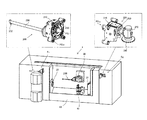
図1は、本発明のツールホルダーを装備する工作機械の一例としての複合加工旋盤の概要を示す説明図である。
全体を符号1で示す複合加工旋盤は、ベッド10上に配設されてワークを把持する第1主軸20と、第1主軸20に対向して配設される第2主軸30を備える。
第1主軸20と第2主軸30の間には、振止め40と加工主軸ヘッド50が配設される。
FIG. 1 is an explanatory diagram showing an outline of a combined machining lathe as an example of a machine tool equipped with the tool holder of the present invention.
The combined machining lathe generally indicated by
Between the first
加工主軸ヘッド50は、図示しないATC装置から供給される旋削工具と回転工具を選択的に装着して必要な加工を行う。加工主軸ヘッド50は、そのスピンドルを第1主軸20側に対向する位置から第2主軸30に対向する位置を越えて旋回動することができる。
The
そして、この複合加工旋盤1は、機内の第1主軸20側にツールホルダー200を格納するストッカーS1と第2主軸30側にツールホルダー300を格納するストッカーS2を備える。
Then, the composite working
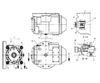
図2は、加工主軸ヘッド50の概要を示す説明図である。
加工主軸ヘッド50は、加工主軸60を有し、加工主軸60は、交換工具のテーパーシャンクを受け入れるテーパーシャンク穴62と工具シャンクを引き込むドローバー64を備える。加工主軸60は、ベアリング66により高速回転自在にヘッド側に支持される。
加工主軸ヘッド50は、X軸、Y軸、Z軸方向に移動制御されるとともに、B軸まわりに回転制御される。
FIG. 2 is an explanatory diagram showing an outline of the
The
The
また、加工主軸ヘッド50は、加工主軸60を中心として、クランプ装置である4基のコレットチャックユニット70を備える。各コレットチャックユニット70は、油圧で操作されるピストン74とピストン74により開閉されるコレット爪72を有し、交換自在に装着されるツールホルダー100側に設けられた4本のプルスタッドPS2を把持する。
Further, the
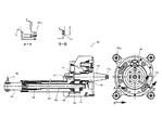
図3は、本発明のツールホルダーの一例としてのツールホルダー100の構造を示す説明図である。
ツールホルダー100はハウジング110を有し、ハウジング110には、テーパーシャンク部130を有する駆動主軸132が回転自在に装備される。駆動主軸132は小歯車134を有し、駆動軸140の歯車142に噛み合う。駆動主軸132はベアリング等で支持されていない、いわゆるフローティング状態で装備されていて、テーパーシャンク部130が工作機械側の加工主軸に挿入されることにより、工作機械側の加工主軸に一体化されて駆動される。駆動軸140は、ボルト122によってハウジング110に装着されている長尺のロングバー120内にベアリング146を介して支持される。
FIG. 3 is an explanatory view showing the structure of a
The
ハウジング110は、4個のプルスタッドPS2と位置決めピン112を有する。
ツールホルダー100は、クーラント用のカップリングや通路を備えて、工作機械側からクーラントの供給を受けることもできる。
The
The
ロングバー120の先端にアングルツールユニット160を連結することができる。このアングルツールユニット160は、駆動軸140の回転を直角に変換して回転工具162を駆動する機構を備える。このアングルツールユニット160を用いて、例えば800mmの深穴の内壁面に穴明け加工等を施すことが可能である。
このような加工にあっては、ツールホルダー100に大きな曲げ応力等が作用するが、曲げ応力はアングルツールユニット160が装着されるロングバー120、ハウジング110が支持する。
また、ツールホルダー100のハウジング110は、4本のプルスタッドPS2で工作機械の加工主軸ヘッド側に剛性高く保持されているので、駆動主軸132側から工作機械の加工主軸60側への曲げ応力等の抵抗力の伝達も防止され、加工主軸60側の支持構造に負担をかけることも防止される。
The
In such processing, a large bending stress or the like acts on the
The
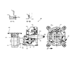
図4は、図1で示したツールホルダー200の構造を示す説明図である。
ツールホルダー200は、ハウジング210を有し、テーパーシャンク部230を有する駆動主軸232が回転自在に装備されている。テーパーシャンク部230の先端にはプルスタッドPS1が設けてあり、小歯車234を有する。駆動主軸232に平行に配置される駆動軸240はベアリング246により高剛性でハウジング210内に支持される。駆動軸240は歯車242を有し、駆動主軸232の歯車234と噛み合う。駆動軸240の中心には、クーラント通路244が形成される。
FIG. 4 is an explanatory view showing the structure of the
The
駆動軸240の先端の穴には、長尺のドリル工具250が挿入される。ドリル工具250の先端にはドリルカッター252と、芯出しカッター254がとりつけられる。ドリルカッター252部には、必要に応じてクーラントが供給される。
ドリル加工を行うと、ツールホルダー200にスラスト方向の大きな力が働くが、その力はベアリング246を介してハウジング210が支持する。
このツールホルダー200もハウジング210の端面に4個のプルスタッドPS2を備え、加工主軸ヘッドに対して剛性高く装着される。また、位置決めピン212を有する。
A
When drilling is performed, a large thrust force acts on the
The
図5は、本発明の他のツールホルダー300の構造を示す説明図である。
ツールホルダー300は、ハウジング310を有し、テーパーシャンク部330を有する駆動主軸332が回転自在に装備されている。テーパーシャンク部330の先端にはプルスタッドPS1が設けてあり、小歯車334を有する。駆動主軸332に平行に配置される駆動軸340はベアリング346により高剛性でハウジング310内に支持される。駆動軸340は歯車342を有し、駆動主軸332の歯車334と噛み合う。
FIG. 5 is an explanatory view showing the structure of another
The
ハウジング310には、サイドカッターホルダーのハウジング350がボルト360により固定される。サイドカッターホルダーのハウジング350内には、駆動軸340に連結される入力軸が設けられ、入力軸の動力は、ギヤボックス370内の歯車機構により直角方向の動力に変換され、出力軸372に伝達される。出力軸372にはサイドカッター380がとりつけられる。
このツールホルダー300も、ハウジング310の端面に4個のプルスタッドPS2を備え、加工主軸ヘッド側に剛性高く装着される。また、位置決めピン312を有する。
A
The
1 複合加工旋盤
10 ベッド
20 第1主軸
30 第2主軸
50 加工主軸ヘッド
100 ツールホルダー
110 ハウジング
DESCRIPTION OF
Claims (2)
ツールホルダーは、ハウジングと、ハウジングの中央部に配置されるテーパーシャンク部を有する駆動主軸と、駆動主軸に平行に配置されてベアリングにより支持される駆動軸と、駆動主軸と駆動軸を伝達する歯車機構と、駆動軸の先端に設けられるツールと、ハウジングの外周部に配設される4本のプルスタッドを備え、
ハウジングは、4本のプルスタッドが工作機械の加工主軸ヘッド側に設けられた4基のコレットチャックに把持されることにより加工主軸ヘッドに剛性高く保持されるとともに、駆動主軸は工作機械の加工主軸に挿入されることにより加工主軸側のベアリングにより支持されることを特徴とするツールホルダー。 A tool holder that is interchangeably mounted on a machining spindle head of a machine tool,
The tool holder includes a housing, a drive main shaft having a tapered shank portion disposed at a central portion of the housing, a drive shaft disposed in parallel to the drive main shaft and supported by a bearing, and a gear that transmits the drive main shaft and the drive shaft. A mechanism, a tool provided at the tip of the drive shaft, and four pull studs disposed on the outer periphery of the housing;
The housing is held rigidly by the machining spindle head by gripping the four pull studs by four collet chucks provided on the machining spindle head side of the machine tool, and the drive spindle is the machining spindle of the machine tool. A tool holder that is supported by a bearing on the machining spindle side by being inserted into the tool.
工作機械の加工主軸ヘッドは、テーパーシャンク穴を有する加工主軸と、加工主軸の周囲に配置される4基のコレットチャックを備え、コレットチャックは、ツールホルダーに設けられた4本のプルスタッドを把持することによりツールホルダーを保持することを特徴とする工作機械。 A machine tool equipped with a tool holder that can be exchanged,
The machining spindle head of a machine tool includes a machining spindle having a tapered shank hole and four collet chucks arranged around the machining spindle. The collet chuck grips four pull studs provided on the tool holder. A machine tool characterized by holding a tool holder.
Priority Applications (4)
| Application Number | Priority Date | Filing Date | Title |
|---|---|---|---|
| JP2007131337A JP2008284643A (en) | 2007-05-17 | 2007-05-17 | Tool holder and machine tool with tool holder |
| EP08405124A EP1992446A1 (en) | 2007-05-17 | 2008-05-02 | Tool holder and machine tool equiped with the tool holder |
| US12/115,593 US7581473B2 (en) | 2007-05-17 | 2008-05-06 | Tool holder and machine tool equipped with the tool holder |
| CNA2008101007089A CN101306477A (en) | 2007-05-17 | 2008-05-16 | Tool holder and machine tool equipped with the tool holder |
Applications Claiming Priority (1)
| Application Number | Priority Date | Filing Date | Title |
|---|---|---|---|
| JP2007131337A JP2008284643A (en) | 2007-05-17 | 2007-05-17 | Tool holder and machine tool with tool holder |
Publications (2)
| Publication Number | Publication Date |
|---|---|
| JP2008284643A true JP2008284643A (en) | 2008-11-27 |
| JP2008284643A5 JP2008284643A5 (en) | 2009-01-15 |
Family
ID=39628956
Family Applications (1)
| Application Number | Title | Priority Date | Filing Date |
|---|---|---|---|
| JP2007131337A Pending JP2008284643A (en) | 2007-05-17 | 2007-05-17 | Tool holder and machine tool with tool holder |
Country Status (4)
| Country | Link |
|---|---|
| US (1) | US7581473B2 (en) |
| EP (1) | EP1992446A1 (en) |
| JP (1) | JP2008284643A (en) |
| CN (1) | CN101306477A (en) |
Cited By (1)
| Publication number | Priority date | Publication date | Assignee | Title |
|---|---|---|---|---|
| JP4542626B1 (en) * | 2009-10-01 | 2010-09-15 | ヤマザキマザック株式会社 | Angle tool holder for 5-sided machining |
Families Citing this family (5)
| Publication number | Priority date | Publication date | Assignee | Title |
|---|---|---|---|---|
| WO2011030432A1 (en) * | 2009-09-10 | 2011-03-17 | ヤマザキマザック株式会社 | Attachment unit for machining of five surfaces |
| ITTV20120043A1 (en) * | 2012-03-21 | 2013-09-22 | Almerino Canuto | CANNON DRILL CHANGE DEVICE FOR DEEP HOLE DRILLS |
| CN103752855A (en) * | 2014-01-17 | 2014-04-30 | 沈阳黎明航空发动机(集团)有限责任公司 | Method for lathing stepped deep hole of blade of aviation engine |
| CN111266635B (en) * | 2020-02-10 | 2022-09-13 | 大连理工大学 | Crystallizer copper pipe inner cavity processing machine tool |
| GB2597699B (en) * | 2020-07-30 | 2022-10-12 | Saab Seaeye Ltd | Tool attachment, tool changer and corresponding method of use |
Family Cites Families (17)
| Publication number | Priority date | Publication date | Assignee | Title |
|---|---|---|---|---|
| US2645952A (en) * | 1949-08-10 | 1953-07-21 | Boyar Schultz Corp | Deep drilling attachment |
| US2869402A (en) * | 1954-09-30 | 1959-01-20 | Boyar Schultz Corp | Deep drilling attachment |
| US2833546A (en) * | 1956-12-19 | 1958-05-06 | Victor C Johnson | Universal tool holder |
| US3115798A (en) * | 1962-08-27 | 1963-12-31 | Carlton S Donaway | Lathe spindle and collet stops |
| US3719254A (en) * | 1971-11-10 | 1973-03-06 | Dotco Inc | Lubricated angle drive attachment for air operated tool |
| JPS6033617B2 (en) | 1981-12-02 | 1985-08-03 | 東芝機械株式会社 | Indexing and tightening device for attachments in machine tools |
| DE8402787U1 (en) * | 1984-02-01 | 1985-05-30 | Werkzeugmaschinenfabrik Adolf Waldrich Coburg Gmbh & Co, 8630 Coburg | High-speed attachment for drilling, milling and similar machine tools |
| JPS6133832A (en) | 1984-07-27 | 1986-02-17 | Toshiba Mach Co Ltd | Automatic mounting/demounting device for attachment |
| JPH0643006B2 (en) | 1985-11-12 | 1994-06-08 | 豊田工機株式会社 | Attachment tool attachment / detachment device |
| JPS63221941A (en) * | 1987-03-12 | 1988-09-14 | Yamazaki Mazak Corp | Offset tool |
| CH673967A5 (en) * | 1987-10-13 | 1990-04-30 | Prawatool Ag | |
| FR2687338B1 (en) * | 1992-02-13 | 1996-08-14 | Line Sa Henri | IMPROVED MILLING HEAD. |
| JP3657734B2 (en) | 1997-04-11 | 2005-06-08 | 株式会社牧野フライス製作所 | Spindle attachment mounting device for machine tools |
| ATE392971T1 (en) * | 1999-09-30 | 2008-05-15 | Kummer Freres Sa | PROCESSING HEAD |
| JP3908495B2 (en) | 2001-09-10 | 2007-04-25 | ヤマザキマザック株式会社 | Boring bar support device and machine tool |
| DE10147649C2 (en) * | 2001-09-27 | 2003-12-24 | Weeke Bohrsysteme Gmbh | Milling unit |
| TW592882B (en) * | 2001-12-19 | 2004-06-21 | Erowa Ag | Clamping apparatus with a clamping chuck and a work piece carrier releasable connectable thereto |
-
2007
- 2007-05-17 JP JP2007131337A patent/JP2008284643A/en active Pending
-
2008
- 2008-05-02 EP EP08405124A patent/EP1992446A1/en not_active Withdrawn
- 2008-05-06 US US12/115,593 patent/US7581473B2/en active Active
- 2008-05-16 CN CNA2008101007089A patent/CN101306477A/en active Pending
Cited By (3)
| Publication number | Priority date | Publication date | Assignee | Title |
|---|---|---|---|---|
| JP4542626B1 (en) * | 2009-10-01 | 2010-09-15 | ヤマザキマザック株式会社 | Angle tool holder for 5-sided machining |
| WO2011039886A1 (en) * | 2009-10-01 | 2011-04-07 | ヤマザキマザック株式会社 | 5-face machining angle tool holder |
| US8708623B2 (en) | 2009-10-01 | 2014-04-29 | Yamazaki Mazak Corporation | Angle tool holder for five-face machining |
Also Published As
| Publication number | Publication date |
|---|---|
| US7581473B2 (en) | 2009-09-01 |
| CN101306477A (en) | 2008-11-19 |
| EP1992446A1 (en) | 2008-11-19 |
| US20080284117A1 (en) | 2008-11-20 |
Similar Documents
| Publication | Publication Date | Title |
|---|---|---|
| JP4890593B2 (en) | Grab mechanism such as tool, chuck, clamp mechanism | |
| JP2001287102A (en) | Combined machining machine tool | |
| US7631407B2 (en) | Machine tool and method for cutting machining of work pieces | |
| JP4542626B1 (en) | Angle tool holder for 5-sided machining | |
| JP2008284643A (en) | Tool holder and machine tool with tool holder | |
| JP2010284768A5 (en) | ||
| WO2011030432A1 (en) | Attachment unit for machining of five surfaces | |
| CN201471151U (en) | Multidirectional automated processing machine tool | |
| JP4765790B2 (en) | Grinding wheel attachment / detachment structure | |
| JP2008284643A5 (en) | ||
| JP2019123063A (en) | Holder and machine tool | |
| JP2007015020A (en) | Workpiece rotating device | |
| JP5317492B2 (en) | Tool spindle and chuck spindle with common parts | |
| JP2013018098A (en) | Multi-spindle machine tool | |
| JP2007331060A (en) | Attaching and detaching structure of grinding wheel | |
| JP2001322001A (en) | Composite working lathe | |
| JP2000015504A (en) | Turning center and its tool rest | |
| JP2010089202A (en) | Chuck for spindle, clamp mechanism, and tool clamping mechanism | |
| JPH0722843B2 (en) | Turret for combined machining lathe | |
| JP5474266B1 (en) | Internal turning attachment for machine tools | |
| JP5455187B2 (en) | Counterbore tool for machining center | |
| JP4721894B2 (en) | Cutting device | |
| KR20100113897A (en) | Multi spindle machine in 2 spindle | |
| JP2008073786A (en) | Cutting work tool and cutting work method | |
| JP2001087930A (en) | End mill holder of lathe |
Legal Events
| Date | Code | Title | Description |
|---|---|---|---|
| A521 | Request for written amendment filed |
Free format text: JAPANESE INTERMEDIATE CODE: A523 Effective date: 20081113 |
|
| A621 | Written request for application examination |
Free format text: JAPANESE INTERMEDIATE CODE: A621 Effective date: 20081113 |
|
| A131 | Notification of reasons for refusal |
Free format text: JAPANESE INTERMEDIATE CODE: A131 Effective date: 20081216 |
|
| A131 | Notification of reasons for refusal |
Free format text: JAPANESE INTERMEDIATE CODE: A131 Effective date: 20090414 |
|
| A02 | Decision of refusal |
Free format text: JAPANESE INTERMEDIATE CODE: A02 Effective date: 20090915 |