JP2008230266A - Shock absorbing steering column device - Google Patents

Shock absorbing steering column device Download PDF

Info

Publication number
JP2008230266A
JP2008230266A JP2007068279A JP2007068279A JP2008230266A JP 2008230266 A JP2008230266 A JP 2008230266A JP 2007068279 A JP2007068279 A JP 2007068279A JP 2007068279 A JP2007068279 A JP 2007068279A JP 2008230266 A JP2008230266 A JP 2008230266A
Authority
JP
Japan
Prior art keywords
steering column
pair
portions
energy absorbing
stroke
Prior art date
Legal status (The legal status is an assumption and is not a legal conclusion. Google has not performed a legal analysis and makes no representation as to the accuracy of the status listed.)
Pending
Application number
JP2007068279A
Other languages
Japanese (ja)
Inventor
Takashi Yoshimura
隆 吉村
Yasuyuki Matsuda
靖之 松田
Sastranegara Azhari
サストラネガラ アズハリ
Takeshi Momo
雄志 百々
Current Assignee (The listed assignees may be inaccurate. Google has not performed a legal analysis and makes no representation or warranty as to the accuracy of the list.)
NSK Ltd
Original Assignee
NSK Ltd
Priority date (The priority date is an assumption and is not a legal conclusion. Google has not performed a legal analysis and makes no representation as to the accuracy of the date listed.)
Filing date
Publication date
Application filed by NSK Ltd filed Critical NSK Ltd
Priority to JP2007068279A priority Critical patent/JP2008230266A/en
Publication of JP2008230266A publication Critical patent/JP2008230266A/en
Pending legal-status Critical Current

Links

Images

Landscapes

  • Steering Controls (AREA)

Abstract

【課題】二次衝突時に運転者に衝撃荷重が加わっても運転者に与えるダメージを低減する衝撃吸収式ステアリングコラム装置を提供する。
【解決手段】インナコラム20と、車体側部材に固定されている支持ブラケット30と、支持ブラケットに支持されて車両前後方向に移動自在とされている移動ブラケット32と、支持ブラケットと移動ブラケットとの間に装着した1本のエネルギ吸収部材48とを備えている。エネルギ吸収部材は、インナコラムのストローク後半に塑性変形するストローク後半塑性領域48cの変形抵抗が、インナコラムのストロークの初期からストローク後半までに塑性変形するストローク前半塑性領域48a,48b,48b1の変形抵抗と比べて大きくなるように形成されている。
【選択図】図4
An impact-absorbing steering column device that reduces damage to a driver even when an impact load is applied to the driver during a secondary collision is provided.
An inner column, a support bracket fixed to a vehicle body side member, a moving bracket supported by the support bracket and movable in the vehicle front-rear direction, and the support bracket and the moving bracket. And one energy absorbing member 48 mounted therebetween. In the energy absorbing member, the deformation resistance of the latter half stroke plastic region 48c that plastically deforms in the second half stroke of the inner column is the deformation resistance of the first half stroke plastic regions 48a, 48b, and 48b1 that plastically deform from the initial stroke of the inner column to the second half stroke. It is formed to be larger than
[Selection] Figure 4

Description

本発明は、二次衝突時に運転者に加わる衝撃荷重を緩和する衝撃吸収式ステアリングコラム装置に関する。   The present invention relates to an impact absorption type steering column device that relieves an impact load applied to a driver during a secondary collision.

衝突事故の際には、自動車が他の自動車等と衝突する一次衝突に続いて、運転者の身体がステアリングホイールに衝突する二次衝突が発生する。この二次衝突の際に運転者の身体に加わる衝撃荷重を緩和し、運転者の身体に重大な損傷を与えることを防止するものとして、衝撃吸収式ステアリングコラム装置が知られている。
従来の衝撃吸収式ステアリングコラム装置として、例えば特許文献1、特許文献2に示すように、二次衝突時に、ステアリングコラムが車両前後方向の前方にストロークすると同時に、塑性変形によって衝撃荷重を吸収するエネルギ吸収部材を備えた装置がある。
特許第3389767号公報 特許第3612971号公報
In the event of a collision accident, a secondary collision in which the driver's body collides with the steering wheel occurs following a primary collision in which the automobile collides with another automobile or the like. 2. Description of the Related Art An impact absorbing steering column device is known as a device that relieves an impact load applied to a driver's body during the secondary collision and prevents serious damage to the driver's body.
As a conventional shock absorption type steering column device, for example, as shown in Patent Document 1 and Patent Document 2, at the time of a secondary collision, the steering column strokes forward in the vehicle front-rear direction, and at the same time, absorbs an impact load by plastic deformation. There is an apparatus provided with an absorbing member.
Japanese Patent No. 3389767 Japanese Patent No. 3612971

ところで、ステアリングコラムがストローク限界位置までストロークした際(ステアリングコラムの底着きの際)に衝撃吸収荷重が急激に上昇してしまうおそれがある。そこで、ステアリングコラムの底着き直前に衝撃吸収荷重が緩やかに増加していき、底着きの際には所定値以下の衝撃吸収荷重となることが望ましい。
しかし、特許文献1の装置のエネルギ吸収部材は、ステアリングコラムのストローク変化に応じて衝撃荷重の吸収能力を可変とする構造としていないので、衝撃吸収荷重が急激に大きくなるおそれがある。すなわち、特許文献1の装置は、図28で示す衝撃吸収特性のように、ステアリングコラムのストローク初期位置から底着きまでの間、一定の衝撃荷重しか吸収しないので、底着きの際に衝撃吸収荷重が急激に上昇してしまうのである。
By the way, when the steering column strokes to the stroke limit position (when the steering column bottoms out), there is a possibility that the shock absorbing load suddenly increases. Therefore, it is desirable that the shock absorbing load gradually increases immediately before the steering column reaches the bottom, and the shock absorbing load is equal to or less than a predetermined value at the bottom.
However, since the energy absorbing member of the device of Patent Document 1 does not have a structure in which the absorbing capacity of the impact load can be changed according to the change in the stroke of the steering column, the impact absorbing load may increase rapidly. That is, since the apparatus of Patent Document 1 absorbs only a constant impact load from the initial stroke position of the steering column to the bottoming, as in the shock absorbing characteristic shown in FIG. 28, the shock absorbing load at the time of bottoming. Will rise rapidly.

また、特許文献2の装置のエネルギ吸収部材は、エネルギ吸収部材を固定する部材(係止部)の形状等を変更することで、ステアリングコラムの底着の際の大きな衝撃荷重を吸収することができるが、このようにすると、前記係止部等の部材の製造コストの面で問題があるとともに、ステアリングコラムのストローク変化に応じて衝撃吸収特性を変更することが難しいという問題もある。   In addition, the energy absorbing member of the device of Patent Document 2 can absorb a large impact load when the steering column is attached to the bottom by changing the shape or the like of a member (locking portion) that fixes the energy absorbing member. However, in this case, there are problems in terms of manufacturing costs of the members such as the locking portions, and there is also a problem that it is difficult to change the shock absorption characteristics in accordance with the change in the stroke of the steering column.

そこで、本発明は、上記従来例の未解決の課題に着目してなされたものであり、二次衝突時に運転者に衝撃荷重が加わっても急激な衝撃吸収荷重の変化を低減することができるとともに、製造コストの低減化を図ることができる衝撃吸収式ステアリングコラム装置を提供することを目的としている。   Therefore, the present invention has been made paying attention to the unsolved problems of the above-described conventional example, and even if an impact load is applied to the driver at the time of a secondary collision, it is possible to reduce a sudden change in the shock absorption load. At the same time, an object of the present invention is to provide an impact absorption type steering column device capable of reducing the manufacturing cost.

上記目的を達成するために、請求項1に係る衝撃吸収式ステアリングコラム装置は、内側にステアリングシャフトを回転自在に支持し、二次衝突時に車両前後方向の前方に向けてストロークするステアリングコラムと、このステアリングコラムに固定された移動部材と、車体側部材に固定されて二次衝突時の衝撃荷重が入力しても車両前後方向に変位しない固定部材と、塑性変形自在な金属部材で成形されており、二次衝突時に、前記移動部材及び前記固定部材の何れかに設けた扱き部材により扱かれることで塑性変形して衝撃エネルギを吸収するエネルギ吸収部材と、を備えた衝撃吸収式ステアリングコラム装置において、前記エネルギ吸収部材を、前記ステアリングコラムのストローク後半に塑性変形するストローク後半塑性領域の変形抵抗が、前記ステアリングコラムのストロークの初期からストローク後半までに塑性変形するストローク前半塑性領域の変形抵抗と比べて大きくなるように形成したことを特徴とする衝撃吸収式ステアリングコラム装置である。   In order to achieve the above object, an impact absorption type steering column apparatus according to claim 1, a steering column that rotatably supports a steering shaft inside and strokes forward in a vehicle longitudinal direction at the time of a secondary collision, Molded with a moving member fixed to the steering column, a fixed member fixed to the vehicle body side member and not displaced in the longitudinal direction of the vehicle even when an impact load at the time of a secondary collision is input, and a plastically deformable metal member. And an energy absorbing member that absorbs impact energy by being plastically deformed by being handled by a handling member provided on either the moving member or the fixed member at the time of a secondary collision. In the second half stroke plastic region, the energy absorbing member is plastically deformed in the second half stroke of the steering column. Anti is a shock absorbing type steering column apparatus is characterized in that formed such that the larger than a stroke early plastic range deformation resistance to plastic deformation from an initial stroke of the steering column until the second half stroke.

また、請求項2記載の発明は、請求項1記載の衝撃吸収式ステアリングコラム装置において、前記ストローク後半塑性領域に加工硬化を施した。
また、請求項3記載の発明は、請求項1又は2記載の衝撃吸収式ステアリングコラム装置において、前記ストローク後半塑性領域及び前記ストローク前半塑性領域の一方に、前記ストローク後半塑性領域の変形抵抗が大きくなるように熱処理を施した。
According to a second aspect of the present invention, in the shock absorbing steering column device according to the first aspect, the second half plastic region of the stroke is work-hardened.
According to a third aspect of the present invention, in the shock absorbing type steering column device according to the first or second aspect, a deformation resistance of the second half stroke plastic region is large in one of the second half stroke plastic region and the first half stroke plastic region. Heat treatment was applied so that

また、請求項4記載の発明は、請求項1乃至3の何れかに記載の衝撃吸収式ステアリングコラム装置において、前記ストローク後半塑性領域を、前記ストローク前半塑性領域に比べて前記扱き部材に扱かれて塑性変形する量が増大する形状とした。
また、請求項5記載の発明は、請求項1乃至4の何れかに記載の衝撃吸収式ステアリングコラム装置において、前記ストローク後半塑性領域を、前記ストローク前半塑性領域に比べて前記ステアリングコラムのストローク方向に直交する断面積を大きくした。
According to a fourth aspect of the present invention, in the shock absorbing steering column device according to any one of the first to third aspects, the second half plastic area of the stroke is handled by the handling member as compared with the first half plastic area of the stroke. Thus, the shape increases the amount of plastic deformation.
According to a fifth aspect of the present invention, in the shock absorbing steering column device according to any one of the first to fourth aspects, the stroke latter half plastic region is more in the stroke direction of the steering column than the pre-stroke half plastic region. The cross-sectional area orthogonal to is increased.

さらに、請求項6記載の発明は、請求項1乃至5の何れかに記載の衝撃吸収式ステアリングコラム装置前記エネルギ吸収部材を金属線で形成した。
さらにまた、請求項7記載の発明は、請求項1乃至5の何れかに記載の衝撃吸収式ステアリングコラム装置において、前記エネルギ吸収部材を金属板で形成した。
Further, in the invention described in claim 6, the energy absorbing member of the shock absorption type steering column device according to any one of claims 1 to 5 is formed of a metal wire.
The invention according to claim 7 is the shock absorption type steering column apparatus according to any one of claims 1 to 5, wherein the energy absorbing member is formed of a metal plate.

この発明によれば、二次衝突時に運転者に衝撃荷重が加わっても、エネルギ吸収部材のステアリングコラムのストローク後半に塑性変形するストローク後半塑性領域の変形抵抗が、エネルギ吸収部材のステアリングコラムのストロークの初期からストローク後半までに塑性変形するストローク前半塑性領域の変形抵抗と比べて大きくなるようにしているので、ステアリングコラムのストローク後半の衝撃吸収荷重を緩やかに増加させていき、ステアリングコラムが底着きする(ステアリングコラムがストローク限界位置までストロークする)際に所定値以下の衝撃吸収荷重となるように大きな衝撃荷重を吸収することができる。   According to the present invention, even if an impact load is applied to the driver at the time of the secondary collision, the deformation resistance in the latter half plastic region that undergoes plastic deformation in the latter half stroke of the steering column of the energy absorbing member is the stroke of the steering column of the energy absorbing member. Since it is designed to be larger than the deformation resistance in the semi-plastic region before the stroke that plastically deforms from the initial stage to the latter half of the stroke, the shock absorption load in the latter half of the stroke of the steering column is gradually increased, and the steering column settles down. A large impact load can be absorbed so that the impact absorption load is a predetermined value or less when the steering column is moved to the stroke limit position.

以下、本発明を実施するための最良の形態(以下、実施形態という。)を、図面を参照しながら詳細に説明する。
図1は、本発明に係る車両を模式的に示した図である。
符号12で示す第1実施形態の衝撃吸収式ステアリングコラム装置には、その車両前後方向の後端にステアリングホイール13を装着したステアリングシャフト11が回転自在に支持されている。ステアリングシャフト11の車両前後方向の前端には、自在継手14を介して伸縮可能な中間シャフト15が連結されている。
Hereinafter, the best mode for carrying out the present invention (hereinafter referred to as an embodiment) will be described in detail with reference to the drawings.
FIG. 1 is a diagram schematically showing a vehicle according to the present invention.
In the shock absorbing steering column apparatus of the first embodiment indicated by reference numeral 12, a steering shaft 11 having a steering wheel 13 attached to the rear end in the vehicle front-rear direction is rotatably supported. An intermediate shaft 15 that can be expanded and contracted is connected to the front end of the steering shaft 11 in the vehicle longitudinal direction via a universal joint 14.

この中間シャフト15の下端には、自在継手16を介してラック・ピニオン式のステアリングギヤ17が連結され、このステアリングギヤ17には、タイロッド18等を介して転舵輪19が連結され、ステアリングホイール13を操舵することにより転舵輪19を転舵することができる。なお、本実施形態の衝撃吸収式ステアリングコラム装置12の車両前後方向の後方には、コンビスイッチやコラムカバー等の周辺部品Pが配置されている。   A rack and pinion type steering gear 17 is connected to the lower end of the intermediate shaft 15 via a universal joint 16, and a steered wheel 19 is connected to the steering gear 17 via a tie rod 18 and the like. The steered wheel 19 can be steered by steering. In addition, peripheral components P such as a combination switch and a column cover are arranged behind the shock absorbing steering column device 12 of the present embodiment in the vehicle front-rear direction.

(第1実施形態)
図2から図6は、第1実施形態の衝撃吸収式ステアリングコラム装置12を示すものである。図2は、本実施形態の衝撃吸収式ステアリングコラム装置12を車幅方向から示した図である。図3は、図2のA−A線矢視図である。図4は、図2のB−B線矢視図である。図5は、本実施形態で使用されているエネルギ吸収部材を示す図である。図6は、第1実施形態の衝撃吸収式ステアリングコラム装置12の衝撃荷重吸収特性及びモデル図を示すものである。
(First embodiment)
2 to 6 show the shock absorption type steering column device 12 of the first embodiment. FIG. 2 is a view showing the shock absorbing steering column device 12 of the present embodiment from the vehicle width direction. FIG. 3 is a view taken along line AA in FIG. 4 is a view taken in the direction of arrows BB in FIG. FIG. 5 is a diagram showing an energy absorbing member used in the present embodiment. FIG. 6 shows an impact load absorption characteristic and a model diagram of the impact absorption type steering column device 12 of the first embodiment.

本実施形態の衝撃吸収式ステアリングコラム装置12は、車両前後方向に延在して配置したインナコラム20と、車体側部材22に固定され、インナコラム20の車体前後方向の前端部を枢軸ピン24を介して連結しているコラム連結ブラケット26と、インナコラム20の車体前後方向の後方側に軸方向に摺動自在に外嵌されているアウタコラム28と、車体側部材22に固定されている支持ブラケット30と、アウタコラム28の上方及び側部を囲みながら支持ブラケット30に支持されて車両前後方向に移動自在とされている移動ブラケット32と、円筒状のアウタコラム28の下側に膨出して形成したディスタンスブラケット34に形成したコラム側通孔36と、ディスタンスブラケット34に当接する移動ブラケット32の側板32aに形成したブラケット側通孔40と、コラム側通孔36及びブラケット側通孔40を挿通しているチルトロッド42と、操作レバー44の揺動操作によりチルトロッド42を介して移動ブラケット32をアウタコラム28に結合、或いは結合解除するロック機構46と、支持ブラケット30と移動ブラケット32との間に装着した1本のエネルギ吸収部材48とを備えている。そして、アウタコラム28内の車体前後方向の後方側に、前述したステアリングホイール13を装着したステアリングシャフト11がコラム連結ブラケット26に対して回転自在に支持されている。   The shock absorbing steering column device 12 of the present embodiment is fixed to an inner column 20 that extends in the vehicle front-rear direction and a vehicle body side member 22, and a front end portion of the inner column 20 in the vehicle body front-rear direction is connected to a pivot pin 24. Are fixed to the vehicle body side member 22, the column connection bracket 26 connected via the outer column 28, the outer column 28 slidably fitted in the axial direction on the rear side of the inner column 20 in the longitudinal direction of the vehicle body. A support bracket 30, a moving bracket 32 supported by the support bracket 30 so as to surround the upper and side portions of the outer column 28, and movable in the vehicle front-rear direction, and bulges below the cylindrical outer column 28. The column side through hole 36 formed in the distance bracket 34 formed in this manner, and the side plate 3 of the moving bracket 32 that contacts the distance bracket 34. The bracket side through hole 40 formed in a, the tilt rod 42 inserted through the column side through hole 36 and the bracket side through hole 40, and the movable bracket 32 via the tilt rod 42 by the swinging operation of the operation lever 44. A lock mechanism 46 that couples to or releases the coupling from the outer column 28 and a single energy absorbing member 48 that is mounted between the support bracket 30 and the moving bracket 32 are provided. The steering shaft 11 on which the above-described steering wheel 13 is mounted is rotatably supported on the column connection bracket 26 on the rear side of the outer column 28 in the longitudinal direction of the vehicle body.

前記コラム側通孔36は、ディスタンスブラケット34において長軸が車両前後方向に延在するように長孔形状として形成されている。
ブラケット側通孔40は、ディスタンスブラケット34に当接する移動ブラケット32の側板32aに、長軸が車両上下方向に延在するように長孔形状として形成されている。
次に、移動ブラケット32、支持ブラケット30及びエネルギ吸収部材48の具体的な構成について、図3から図5を参照して詳細に説明する。
The column side through hole 36 is formed in a long hole shape such that the long axis of the distance bracket 34 extends in the vehicle front-rear direction.
The bracket side through hole 40 is formed in a long hole shape on the side plate 32a of the moving bracket 32 that contacts the distance bracket 34 so that the long axis extends in the vehicle vertical direction.
Next, specific configurations of the moving bracket 32, the support bracket 30, and the energy absorbing member 48 will be described in detail with reference to FIGS.

移動ブラケット32は、図3に示すように、上板32bと、横断面コ字状となるように上板32bの幅方向両縁部から一体に形成されて互いに平行に延在している一対の側板32aとを備えている。上板32bの両側部には、一対の案内レール32cが突出して形成されており、移動ブラケット32全体が車両前後方向に移動自在となるように支持ブラケット30の一対の案内溝30cに係合している。そして、アウタコラム28に対して車両上下方向の上方に配置した上板32bの上面には、第1凸部32dが突出して形成されている。そして、図4に示すように、この第1凸部32dの車両前後方向の前方を向いているコーナー部は、所定の曲率で丸みを付けたR部32e,32fとして形成されている。   As shown in FIG. 3, the moving bracket 32 is formed integrally with the upper plate 32 b from both edges in the width direction of the upper plate 32 b so as to have a U-shaped cross section, and extends in parallel with each other. Side plate 32a. A pair of guide rails 32c are formed on both sides of the upper plate 32b so as to engage with the pair of guide grooves 30c of the support bracket 30 so that the entire moving bracket 32 is movable in the vehicle longitudinal direction. ing. A first protrusion 32d is formed to protrude from the upper surface of the upper plate 32b disposed above the outer column 28 in the vehicle vertical direction. As shown in FIG. 4, corner portions of the first convex portion 32d facing forward in the vehicle front-rear direction are formed as R portions 32e and 32f rounded with a predetermined curvature.

支持ブラケット30は、図3及び図4に示すように、外観が矩形状のブラケット本体30aと、このブラケット本体30aに一体形成され、コラム連結ブラケット26の連結部26aを介して固定ボルト50で車体側部材22に連結される連結部30bと、前述した移動ブラケット32の一対の案内レール32cが嵌まり込むように車両前後方向に延在して設けられている一対の案内溝30cとを備えている。   As shown in FIGS. 3 and 4, the support bracket 30 is integrally formed with the bracket body 30 a having a rectangular external appearance and the bracket body 30 a, and is fixed to the vehicle body by the fixing bolt 50 via the connection portion 26 a of the column connection bracket 26. A connecting portion 30b connected to the side member 22 and a pair of guide grooves 30c provided so as to extend in the vehicle front-rear direction so as to fit the pair of guide rails 32c of the moving bracket 32 described above are provided. Yes.

車体側部材22に固定されたブラケット本体30aには、車両上下方向に連通して開口する開口孔が形成されており、この開口孔は、車両前後方向の前方側に車幅方向長さが大きな領域で開口する第1開口孔30dと、この第1開口孔30dに連続して設けられ、第1開口孔30dより車幅方向長さが小さな領域で開口する第2開口孔30eとされている。また、第2開口孔30eの周囲には、車体側部材22に当接する当接面30fより低い段差面30gが形成されており、この段差面30g上に、前記第2開口孔30eを間に挟んで車幅方向の一方及び他方に略等距離に離間した位置に一対の第2凸部30hが形成されている。これら一対の第2凸部30hの車両前後方向の後方を向く面は、所定の曲率で車両前後方向の方向側に突出するR部30iとして形成されている。   The bracket main body 30a fixed to the vehicle body side member 22 is formed with an opening hole that opens in communication with the vehicle in the vertical direction. This opening hole has a large vehicle width direction length on the front side in the vehicle front-rear direction. A first opening hole 30d that opens in a region, and a second opening hole 30e that is provided continuously to the first opening hole 30d and opens in a region that is smaller in the vehicle width direction than the first opening hole 30d. . Further, a step surface 30g lower than the contact surface 30f that contacts the vehicle body side member 22 is formed around the second opening hole 30e, and the second opening hole 30e is interposed on the step surface 30g. A pair of second convex portions 30h are formed at positions spaced substantially equidistant from one and the other in the vehicle width direction across the vehicle. The surfaces of the pair of second convex portions 30h that face the rear in the vehicle front-rear direction are formed as R portions 30i that protrude in the vehicle front-rear direction direction side with a predetermined curvature.

そして、ブラケット本体30aの第2開口孔30eに、移動ブラケット32の上板32bに形成した第1凸部32dが下方から進入し、段差面30gに対して車両上下方向の上方に位置するように突出している。
エネルギ吸収部材48は、塑性変形自在な断面真円の金属線(針金)を曲げ成形することにより形成されている。
And the 1st convex part 32d formed in the upper board 32b of the movable bracket 32 enters the 2nd opening hole 30e of the bracket main body 30a from below, and it is located above the step surface 30g in the vehicle up-down direction. It protrudes.
The energy absorbing member 48 is formed by bending a metal wire (wire) having a perfectly circular cross section that can be plastically deformed.

このエネルギ吸収部材48は、図5に示すように、エネルギ吸収部材48の軸方向中央部に形成した中央変形部48aと、この中央変形部48aの両端部から一体形成された一対の端部変形部48bと、これら一対の端部変形部48bの曲率縁部48b1からそれぞれ自由端に向かって直線状に延在している直線部48cとを備えている。つまり、このエネルギ吸収部材48は、中央変形部48aが凸状に湾曲して曲げ成形されており、一対の端部変形部48bが、中央変形部48aが凸状に湾曲する方向に対して同一平面内で逆方向に凸状に湾曲して曲げ成形され、直線部48cが、一対の端部変形部48bの曲率縁部48b1から前記平面内において中央変形部48aが凸状に湾曲する方向と同一方向に直線的に延在することで、M字形状に曲げ成形されている。中央変形部48aの曲率半径は、移動ブラケット32の上板32bに形成した第1凸部32dのR部32e,32fに沿うようにその曲率半径と略同一に設定されている。また、一対の端部変形部48bの曲率半径は、支持ブラケット30に形成した一対の第2凸部30hのR部30iに沿うようにその曲率半径と略同一に設定されている。   As shown in FIG. 5, the energy absorbing member 48 includes a central deforming portion 48a formed at the center in the axial direction of the energy absorbing member 48 and a pair of end deformations integrally formed from both ends of the central deforming portion 48a. 48b, and a straight portion 48c extending linearly from the curvature edge portion 48b1 of each of the pair of end portion deformation portions 48b toward the free end. That is, the energy absorbing member 48 is formed by bending the central deformation portion 48a in a convex shape, and the pair of end deformation portions 48b are the same in the direction in which the central deformation portion 48a is curved in a convex shape. The straight portion 48c is bent in a convex shape in the opposite direction in the plane, and the straight portion 48c is curved from the curvature edge portion 48b1 of the pair of end portion deformation portions 48b in the direction in which the central deformation portion 48a is convexly curved in the plane. By extending linearly in the same direction, it is bent into an M shape. The curvature radius of the central deformation portion 48a is set to be substantially the same as the curvature radius along the R portions 32e and 32f of the first convex portion 32d formed on the upper plate 32b of the moving bracket 32. Further, the radius of curvature of the pair of end deforming portions 48 b is set to be substantially the same as the radius of curvature along the R portion 30 i of the pair of second convex portions 30 h formed on the support bracket 30.

ここで、図4から図6では、エネルギ吸収部材48の一対の直線部48cを、黒で塗りつぶした部分で示し、中央変形部48a、一対の端部変形部48b及び曲率縁部48b1を白で示しているが、一対の直線部48cは、塑性変形する際の変形抵抗が、中央変形部48a、一対の端部変形部48b及び曲率縁部48b1と比較して大きくなるように設定されている。つまり、本実施形態では、黒で塗りつぶしている部分の一対の直線部48cをショットピーニングにより加工硬化を施すことで、中央変形部48a、一対の端部変形部48b及び曲率縁部48b1と比較して塑性変形する際の変形抵抗を大きくしている。   Here, in FIGS. 4 to 6, the pair of straight portions 48 c of the energy absorbing member 48 are shown by the portions filled with black, and the central deformed portion 48 a, the pair of end deformed portions 48 b and the curvature edge portion 48 b 1 are white. Although shown, the pair of linear portions 48c are set so that the deformation resistance when plastically deforming is larger than that of the central deformation portion 48a, the pair of end portion deformation portions 48b, and the curvature edge portion 48b1. . In other words, in the present embodiment, the pair of straight portions 48c that are filled with black are processed and hardened by shot peening, so that the center deformed portion 48a, the pair of end deformed portions 48b, and the curvature edge portion 48b1 are compared. The deformation resistance when plastically deforming is increased.

上記構成のエネルギ吸収部材48は、図4に示すように、中央変形部48aが、支持ブラケット30の第2開口孔30eから上方に突出している移動ブラケット32の第1凸部32dの車両前後方向の前方を向く側面に掛け渡され、一対の端部変形部48bが、支持ブラケット30の一対の第2凸部30hの車両前後方向の後方を向く側面に掛け渡されることで、支持ブラケット30と移動ブラケット32との間に装着されている。   As shown in FIG. 4, the energy absorbing member 48 having the above-described configuration has a central deformation portion 48 a that protrudes upward from the second opening hole 30 e of the support bracket 30 in the vehicle longitudinal direction of the first convex portion 32 d of the moving bracket 32. The pair of end deformed portions 48b are stretched over the side surfaces of the pair of second convex portions 30h of the support bracket 30 facing the rear in the vehicle front-rear direction. It is mounted between the moving bracket 32.

ここで、請求項のステアリングコラムがアウタコラム28に対応し、請求項の移動部材が移動ブラケット32に対応し、請求項の固定部材が支持ブラケット30に対応し、請求項の扱き部材が第1凸部32d、一対の第2凸部30hに対応し、請求項のストローク後半塑性領域が一対の直線部48cに対応し、請求項のストローク前半塑性領域が中央変形部48a及び一対の端部変形部48bの曲率縁部48b1までの領域に対応する。   Here, the steering column of the claims corresponds to the outer column 28, the moving member of the claims corresponds to the moving bracket 32, the fixing member of the claims corresponds to the support bracket 30, and the handling member of the claims is the first. Corresponding to the convex portion 32d and the pair of second convex portions 30h, the latter half stroke plastic region of the claims corresponds to the pair of linear portions 48c, and the pre-stroke half plastic region of the claims is the central deformation portion 48a and the pair of end portion deformations. This corresponds to the region up to the curvature edge 48b1 of the portion 48b.

本実施形態の衝撃吸収式ステアリングコラム装置12は、衝突事故の際に以下のように作用して、ステアリングホイール13にぶつかった運転者の身体に加わる衝撃を緩和する。
二次衝突時には、移動ブラケット32がアウタコラム28とともに車両前後方向の前方にストロークする。これに対して、車体側部材22に固定されている支持ブラケット30は車両前後方向に変位せず、そのままの位置に残る。
The shock absorption type steering column device 12 of the present embodiment acts as follows in the event of a collision to alleviate the impact applied to the driver's body that hits the steering wheel 13.
At the time of the secondary collision, the moving bracket 32 strokes forward in the vehicle longitudinal direction together with the outer column 28. On the other hand, the support bracket 30 fixed to the vehicle body side member 22 is not displaced in the vehicle front-rear direction and remains in the position as it is.

この際、移動ブラケット32の第1凸部32dは、図6の(A)のモデル図で示す初期位置から車両前後方向の前方にストロークする。この第1凸部32dが車両前後方向の前方にストロークすることで、(B)のモデル図で示すように、エネルギ吸収部材48の中央変形部48aが第1凸部32dに扱かれて塑性変形していき、一対の端部変形部48b及び曲率縁部48b1が第2凸部30hに扱かれて塑性変形することで、一定の衝撃荷重が吸収されていく。   At this time, the first convex portion 32d of the moving bracket 32 strokes forward in the vehicle longitudinal direction from the initial position shown in the model diagram of FIG. As the first convex portion 32d strokes forward in the vehicle longitudinal direction, the central deformation portion 48a of the energy absorbing member 48 is handled by the first convex portion 32d and plastically deformed as shown in the model diagram of FIG. As a result, the pair of end deformation portions 48b and the curvature edge portion 48b1 are handled by the second convex portion 30h and plastically deformed, so that a constant impact load is absorbed.

そして、さらに移動ブラケット32がストローク後半である底着き位置に向かってストロークしていくと、図6の(C)のモデル図で示すように、加工硬化を施した一対の直線部48cが、一対の第2凸部30hに扱かれて塑性変形していく。
このように、加工硬化を施した一対の直線部48cが塑性変形すると、エネルギ吸収部材48の変形抵抗が増大して衝撃荷重を吸収する能力が増大するので、図6の衝撃荷重吸収特性で明らかなように、ステアリングコラム(アウタコラム28)の底着き直前まで衝撃吸収荷重が緩やかに増加していくとともに、ステアリングコラム(アウタコラム28)の底着きの際には、所定値以下の衝撃荷重吸収特性を得ることができる。
When the moving bracket 32 further strokes toward the bottom position, which is the latter half of the stroke, as shown in the model diagram of FIG. It is handled by the second convex portion 30h and undergoes plastic deformation.
As described above, when the pair of straight portions 48c subjected to work hardening are plastically deformed, the deformation resistance of the energy absorbing member 48 is increased and the ability to absorb the impact load is increased. As described above, the shock absorbing load gradually increases until just before the steering column (outer column 28) bottoms, and when the steering column (outer column 28) bottoms, the shock load is absorbed below a predetermined value. Characteristics can be obtained.

したがって、ステアリングコラム(アウタコラム28)の底着き直前まで衝撃吸収荷重が緩やかに増加していき、底着きの際には所定値以下の衝撃吸収荷重にすることができる。
また、本実施形態ではエネルギ吸収部材48を、金属線を折り曲げることにより構成し、中央変形部48aを、移動ブラケット32の第1凸部32dの車両前後方向の前方を向く側面に掛け渡し、一対の端部変形部48bを、支持ブラケット30の一対の第2凸部30hの車両前後方向の後方を向く側面に掛け渡すだけで、支持ブラケット30と移動ブラケット32との間に簡単に装着することができるので、組み立て作業の能率化を図ることができる。また、金属線を折り曲げることにより造られるエネルギ吸収部材48は、材料の無駄が殆ど生じないため、材料の歩留が向上する。また、エネルギ吸収部材48を加工する為に複雑な型を必要としない。したがって、製造コストの低減化を図ることができる。
なお、エネルギ吸収部材48の断面形状は真円に限らず、楕円、多角形状からなる塑性変形自在な金属線であればよい。
Therefore, the shock absorbing load gradually increases until just before the steering column (outer column 28) is bottomed, and when the bottom is settled, the shock absorbing load can be set to a predetermined value or less.
Further, in the present embodiment, the energy absorbing member 48 is configured by bending a metal wire, and the central deformable portion 48a is stretched over the side surface of the first convex portion 32d of the moving bracket 32 facing the front in the vehicle front-rear direction. The end deformed portion 48b of the support bracket 30 can be easily mounted between the support bracket 30 and the movable bracket 32 simply by hanging over the side surfaces of the pair of second convex portions 30h facing the rear in the vehicle front-rear direction. As a result, the efficiency of the assembly work can be improved. Further, since the energy absorbing member 48 produced by bending the metal wire hardly wastes material, the yield of the material is improved. Further, a complicated mold is not required for processing the energy absorbing member 48. Therefore, the manufacturing cost can be reduced.
In addition, the cross-sectional shape of the energy absorbing member 48 is not limited to a perfect circle, and may be any plastic wire that can be plastically deformed such as an ellipse or a polygon.

(第1実施形態のエネルギ吸収部材の第1変形例)
次に、図7に示すものは、図5で示したエネルギ吸収部材48と異なる第1変形例のエネルギ吸収部材である。この第1変形例のエネルギ吸収部材100は、熱処理を施した部材である。すなわち、塑性変形自在な断面真円の金属線(針金)をM字形状に曲げ成形して形成されており、軸方向中央部に凸状に湾曲して曲げ成形されている中央変形部100aと、この中央変形部100aの両端部から一体形成され、中央変形部100aが凸状に湾曲する方向に対して同一平面内で逆方向に凸状に湾曲して曲げ成形されている一対の端部変形部100bと、これら一対の端部変形部100bの曲率縁部100b1から前記平面内において中央変形部100aが凸状に湾曲する方向と同一方向にそれぞれ自由端に向かって直線状に延在している一対の直線部(黒で塗り潰した部分)100cとを備えている。
(First modification of the energy absorbing member of the first embodiment)
Next, what is shown in FIG. 7 is an energy absorbing member of a first modification different from the energy absorbing member 48 shown in FIG. The energy absorbing member 100 of the first modified example is a member that has been subjected to heat treatment. That is, a centrally deformed portion 100a formed by bending a metal wire (wire) having a perfectly circular cross section that can be plastically deformed into an M-shape, and being bent and bent in a convex shape in the axial center portion; A pair of end portions that are integrally formed from both ends of the central deformation portion 100a and are bent and bent in a convex shape in the opposite direction within the same plane with respect to the direction in which the central deformation portion 100a is curved in a convex shape. The deformable portion 100b and the edge portions 100b1 of the pair of end deformable portions 100b extend linearly toward the free end in the same direction as the central deformable portion 100a in a convex shape in the plane. A pair of straight portions (portions filled in black) 100c.

この第1変形例のエネルギ吸収部材100は、一対の直線部100cと、中央変形部100a、一対の端部変形部100b及び曲率縁部100b1の一方に熱処理を施すことで、一対の直線部100cが塑性変形する際の変形抵抗が、中央変形部100a、一対の端部変形部100b及び曲率縁部100b1と比較して変更されている。
具体的には、一対の直線部100cに熱処理を施す場合には、焼入れ等のバルク熱処理により一対の直線部100cの内部を、中央変形部100a、一対の端部変形部100b及び曲率縁部100b1の内部と比較して硬くする方法や、浸炭、窒化、高周波焼入れ等のサーフェース熱処理により一対の直線部100cの表面を、中央変形部100a、一対の端部変形部100b及び曲率縁部100b1の表面と比較して硬くする方法が考えられる。また、中央変形部100a、一対の端部変形部100b及び曲率縁部100b1に熱処理を施す場合には、焼きなまし等のバルク熱処理により中央変形部100a、一対の端部変形部100b及び曲率縁部100b1の内部を一対の直線部100cの内部と比較して軟らかくする方法や、表面脱炭等のサーフェース熱処理により中央変形部100a、一対の端部変形部100b及び曲率縁部100b1の表面を一対の直線部100cの表面と比較して軟らかくする方法が考えられる。
The energy absorbing member 100 according to the first modification includes a pair of straight portions 100c by applying heat treatment to one of the pair of straight portions 100c and the central deformable portion 100a, the pair of end deformed portions 100b, and the curvature edge portion 100b1. The deformation resistance at the time of plastic deformation is changed compared to the central deformation portion 100a, the pair of end deformation portions 100b, and the curvature edge portion 100b1.
Specifically, when heat treatment is performed on the pair of straight portions 100c, the central deformation portion 100a, the pair of end portion deformation portions 100b, and the curvature edge portion 100b1 are formed inside the pair of straight portions 100c by bulk heat treatment such as quenching. The surface of the pair of straight portions 100c is made to be the center deformed portion 100a, the pair of end deformed portions 100b, and the curvature edge portion 100b1 by a method of hardening compared to the inside of the surface, or by surface heat treatment such as carburizing, nitriding, or induction hardening. A method of making it harder than the surface is conceivable. When heat treatment is performed on the central deformation portion 100a, the pair of end portion deformation portions 100b, and the curvature edge portion 100b1, the central deformation portion 100a, the pair of end portion deformation portions 100b, and the curvature edge portion 100b1 are performed by bulk heat treatment such as annealing. The surface of the central deformed portion 100a, the pair of end deformed portions 100b, and the curvature edge portion 100b1 is made to be softer by a method of softening the inside of the pair of straight portions 100c than the inside of the pair of straight portions 100c or by surface heat treatment such as surface decarburization. A method of softening the surface of the straight portion 100c is conceivable.

ここで、請求項のストローク後半塑性領域が一対の直線部100cに対応し、請求項のストローク前半塑性領域が中央変形部100a、一対の端部変形部100b及び曲率縁部100b1に対応する。
上述した第1変形例のエネルギ吸収部材100を備えた衝撃吸収式ステアリングコラム装置12は、一対の直線部100cと、中央変形部100a、一対の端部変形部100b及び曲率縁部100b1の一方に熱処理を施すことで、一対の直線部100cが塑性変形する際の変形抵抗が、中央変形部100a、一対の端部変形部100b及び曲率縁部100b1と比較して大きくなるように設定されているので、二次衝突時に、一対の直線部100cが塑性変形すると、エネルギ吸収部材100の変形抵抗が増大して衝撃荷重を吸収する能力が増大し、図6の衝撃荷重吸収特性と同様に、ステアリングコラム(アウタコラム28)の底着き直前まで衝撃吸収荷重が緩やかに増加していくとともに、ステアリングコラム(アウタコラム28)の底着きの際には、所定値以下の衝撃荷重吸収特性を得ることができる。
Here, the latter half stroke plastic region of the claims corresponds to the pair of straight portions 100c, and the first half stroke plastic region of the claims corresponds to the central deformation portion 100a, the pair of end portion deformation portions 100b, and the curvature edge portion 100b1.
The shock absorbing steering column device 12 including the energy absorbing member 100 of the first modified example described above is provided on one of the pair of straight portions 100c, the central deformed portion 100a, the pair of end deformed portions 100b, and the curvature edge portion 100b1. By performing the heat treatment, the deformation resistance when the pair of linear portions 100c are plastically deformed is set to be larger than that of the central deformation portion 100a, the pair of end portion deformation portions 100b, and the curvature edge portion 100b1. Therefore, when the pair of straight portions 100c are plastically deformed at the time of the secondary collision, the deformation resistance of the energy absorbing member 100 is increased and the ability to absorb the impact load is increased. As in the impact load absorption characteristic of FIG. The shock absorbing load gradually increases until the bottom of the column (outer column 28) reaches the bottom, and the steering column (outer column 28) During arrived, it is possible to obtain an impact load absorption characteristics of the predetermined value or less.

したがって、エネルギ吸収部材100の一対の直線部100cと、中央変形部100a、一対の端部変形部100b及び曲率縁部100b1の一方に熱処理を施すことで、ステアリングコラム(アウタコラム28)の底着き直前まで衝撃吸収荷重が緩やかに増加していき、底着きの際には所定値以下の衝撃吸収荷重に設定する衝撃荷重吸収特性を得ることができる。   Therefore, the bottom of the steering column (outer column 28) is obtained by performing heat treatment on one of the pair of linear portions 100c, the central deformable portion 100a, the pair of end deformed portions 100b, and the curvature edge portion 100b1 of the energy absorbing member 100. The shock absorbing load gradually increases until just before it is reached, and an impact load absorbing characteristic set to a shock absorbing load equal to or less than a predetermined value can be obtained at the time of bottoming.

(第1実施形態のエネルギ吸収部材の第2変形例)
次に、図8に示すものは、図5で示したエネルギ吸収部材48と異なる第2変形例のエネルギ吸収部材である。
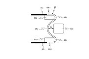
第2変形例のエネルギ吸収部材110は、塑性変形自在な断面真円の金属線(針金)で形成されており、軸方向中央部に凸状に湾曲して曲げ成形されている中央変形部110aと、この中央変形部110aの両端部から一体形成され、中央変形部110aが凸状に湾曲する方向に対して同一平面内で逆方向に凸状に湾曲して曲げ成形されている一対の端部変形部110bと、これら一対の端部変形部110bの曲率縁部110b1から前記平面内において中央変形部110aが凸状に湾曲する方向と同一方向にそれぞれ自由端に向かって曲線状に延在している一対の曲線部(黒で塗り潰した部分)110cとを備えている。
(Second modification of the energy absorbing member of the first embodiment)
Next, what is shown in FIG. 8 is an energy absorbing member of a second modification different from the energy absorbing member 48 shown in FIG.
The energy absorbing member 110 of the second modified example is formed of a metal wire (wire) having a perfectly circular cross section that can be plastically deformed, and a central deformed portion 110a that is bent and bent in a convex shape at the central portion in the axial direction. And a pair of ends that are integrally formed from both end portions of the central deformation portion 110a and are bent and bent in a convex shape in the opposite direction within the same plane with respect to the direction in which the central deformation portion 110a is curved in a convex shape. The curved portion 110b and the curvature edge portion 110b1 of the pair of deformed end portions 110b extend in a curved line toward the free end in the same direction as the curved direction of the central deformable portion 110a in the plane. And a pair of curved portions (portions filled in black) 110c.

一対の曲線部110cは、一対の端部変形部100bの端部に連続する部位同士の間の間隔をL1とすると、自由端に向かうに従い互いの間隔が徐々に大きくなって自由端同士の距離が前記間隔L1より大きな値L2(L1<L2)となるように、自由端に向かうに従い互いに離間する方向に曲がって形成されている。これにより、一対の曲線部110cは、支持ブラケット30の一対の第2凸部30hに扱かれて塑性変形する方向に対して逆方向に曲げて形成されている。   The pair of curved portions 110c has a distance between the free ends that gradually increases toward the free end, assuming that the distance between the portions continuous to the ends of the pair of end deformable portions 100b is L1. Are bent in a direction away from each other toward the free end so that the value L2 (L1 <L2) is larger than the interval L1. Accordingly, the pair of curved portions 110 c are formed by bending in the opposite direction to the direction in which the pair of second convex portions 30 h of the support bracket 30 are handled and plastically deformed.

ここで、請求項のストローク後半塑性領域が一対の曲線部110cに対応し、請求項のストローク前半塑性領域が中央変形部110a、一対の端部変形部110b及び曲率縁部110b1に対応する。
この第2変形例のエネルギ吸収部材110を備えた衝撃吸収式ステアリングコラム装置12は、二次衝突時に、移動ブラケット32の第1凸部32dが車両前後方向の前方にストロークすると、エネルギ吸収部材110の中央変形部110aが第1凸部32dに扱かれて塑性変形していき、一対の端部変形部100b及び曲率縁部110b1が第2凸部30hに扱かれて塑性変形していき、一定の衝撃荷重が吸収されていく。
Here, the latter half stroke plastic region in the claims corresponds to the pair of curved portions 110c, and the first half stroke plastic region in the claims corresponds to the central deformation portion 110a, the pair of end portion deformation portions 110b, and the curvature edge portion 110b1.
In the impact absorbing steering column device 12 including the energy absorbing member 110 of the second modification, the energy absorbing member 110 is moved when the first convex portion 32d of the moving bracket 32 strokes forward in the vehicle longitudinal direction at the time of a secondary collision. The central deformed portion 110a is handled by the first convex portion 32d and plastically deformed, and the pair of end deformed portions 100b and the curvature edge portion 110b1 are handled by the second convex portion 30h and plastically deformed, and are constant. The impact load is absorbed.

そして、さらに移動ブラケット32がストローク後半である底着き位置に向かってストロークしていくと、一対の曲線部110cが、一対の第2凸部30hに扱かれて塑性変形していく。この際、一対の曲線部110cは、一対の第2凸部30hに扱かれて塑性変形する方向に対して逆方向に曲げて形成されており、支持ブラケット30によりL1≒L2となるように矯正されるときの変形抵抗が増大していき、衝撃荷重を吸収する能力が増大していく。   When the moving bracket 32 further strokes toward the bottom position, which is the latter half of the stroke, the pair of curved portions 110c are handled by the pair of second convex portions 30h and plastically deformed. At this time, the pair of curved portions 110c are formed by bending in the opposite direction to the direction of plastic deformation handled by the pair of second convex portions 30h, and are corrected by the support bracket 30 so that L1≈L2. As the deformation resistance increases, the ability to absorb impact loads increases.

したがって、エネルギ吸収部材110の一対の曲線部110cを、支持ブラケット30の一対の第2凸部30hに扱かれて塑性変形する方向に対して逆方向に曲げて形成したことで、ステアリングコラム(アウタコラム28)の底着き直前まで衝撃吸収荷重が緩やかに増加していき、底着きの際には所定値以下の衝撃吸収荷重に設定する衝撃荷重吸収特性を得ることができる。   Therefore, the pair of curved portions 110c of the energy absorbing member 110 are formed by bending the direction opposite to the direction in which the pair of second convex portions 30h of the support bracket 30 are plastically deformed, so that the steering column (outer The shock absorbing load gradually increases until just before the bottom of the column 28), and an impact load absorbing characteristic set to a shock absorbing load of a predetermined value or less can be obtained at the time of bottoming.

(第1実施形態のエネルギ吸収部材の第3変形例)
次に、図9に示すものは、図5で示したエネルギ吸収部材48と異なる第3変形例のエネルギ吸収部材である。
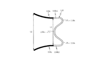
第3変形例のエネルギ吸収部材120は、塑性変形自在な断面真円の金属線(針金)で形成されており、軸方向中央部に凸状に湾曲して曲げ成形されている中央変形部120aと、この中央変形部120aの両端部から一体形成され、中央変形部120aが凸状に湾曲する方向に対して同一平面内で逆方向に凸状に湾曲して曲げ成形されている一対の端部変形部120bと、これら一対の端部変形部120bの曲率縁部120b1から前記平面内において中央変形部120aが凸状に湾曲する方向と同一方向にそれぞれ自由端に向かって直線状に延在している一対の大断面直線部(黒で塗り潰した部分)120cとを備えている。
(The 3rd modification of the energy absorption member of a 1st embodiment)
Next, what is shown in FIG. 9 is an energy absorbing member of a third modified example different from the energy absorbing member 48 shown in FIG.
The energy absorbing member 120 of the third modified example is formed of a metal wire (wire) having a perfectly circular cross section that can be plastically deformed, and a central deformed portion 120a that is bent and bent in a convex shape at the central portion in the axial direction. And a pair of ends that are integrally formed from both ends of the central deformation portion 120a and are bent and bent in a convex shape in the opposite direction within the same plane with respect to the direction in which the central deformation portion 120a is curved in a convex shape. The linearly deforming portion 120b and the edge 120b1 of the pair of end deforming portions 120b extend linearly toward the free end in the same direction as the central deforming portion 120a in a convex shape in the plane. And a pair of large cross-section straight line portions (portions filled in black) 120c.

一対の大断面直線部120cは、中央変形部120a及び一対の端部変形部120bと比較して断面積が大きく設定されている。
ここで、請求項のストローク後半塑性領域が一対の大断面直線部120cに対応し、請求項のストローク前半塑性領域が中央変形部120a及び一対の端部変形部120bの曲率縁部120b1までの領域に対応する。
The pair of large cross-section linear portions 120c have a larger cross-sectional area than the central deformable portion 120a and the pair of end deformed portions 120b.
Here, the latter stroke plastic region of the claim corresponds to the pair of large cross-sectional straight portions 120c, and the first stroke half plastic region of the claim is a region to the curvature edge portion 120b1 of the central deformation portion 120a and the pair of end deformation portions 120b. Corresponding to

この第3変形例のエネルギ吸収部材120を備えた衝撃吸収式ステアリングコラム装置12は、二次衝突時に、移動ブラケット32の第1凸部32dが車両前後方向の前方にストロークすると、エネルギ吸収部材120の中央変形部120aが第1凸部32dに扱かれて塑性変形していき、一対の端部変形部120b及び曲率縁部120b1が第2凸部30hに扱かれて塑性変形していき、一定の衝撃荷重が吸収されていく。   In the impact absorbing steering column device 12 including the energy absorbing member 120 of the third modified example, when the first convex portion 32d of the moving bracket 32 strokes forward in the vehicle longitudinal direction at the time of a secondary collision, the energy absorbing member 120 is used. The central deformed portion 120a is handled and plastically deformed by the first convex portion 32d, and the pair of end deformed portions 120b and the curvature edge portion 120b1 are handled and plastically deformed by the second convex portion 30h. The impact load is absorbed.

そして、さらに移動ブラケット32がストローク後半である底着き位置に向かってストロークしていくと、一対の大断面直線部120cが、一対の第2凸部30hに扱かれて塑性変形していく。この際、一対の大断面直線部120cは、中央変形部120a、一対の端部変形部120b及び曲率縁部120b1に対して断面積が大きいので塑性変形する際の変形抵抗が増大し、衝撃荷重を吸収する能力が増大していく。   When the moving bracket 32 further strokes toward the bottom position, which is the latter half of the stroke, the pair of large cross-section straight portions 120c are handled by the pair of second convex portions 30h and plastically deformed. At this time, the pair of large cross-section straight portions 120c have a larger cross-sectional area than the central deformation portion 120a, the pair of end portion deformation portions 120b, and the curvature edge portion 120b1, so that the deformation resistance at the time of plastic deformation increases, The ability to absorb is increasing.

したがって、エネルギ吸収部材120の一対の大断面直線部120cを中央変形部120a、一対の端部変形部120b及び曲率縁部120b1と比較して断面積を大きくしたことで、ステアリングコラム(アウタコラム28)の底着き直前まで衝撃吸収荷重が緩やかに増加していき、底着きの際には所定値以下の衝撃吸収荷重に設定する衝撃荷重吸収特性を得ることができる。   Therefore, the pair of large cross-sectional straight portions 120c of the energy absorbing member 120 are made larger in cross-sectional area than the central deformable portion 120a, the pair of end deformed portions 120b, and the curvature edge portion 120b1, thereby the steering column (outer column 28). The shock absorbing load gradually increases until just before the bottoming), and an impact load absorbing characteristic set to a shock absorbing load of a predetermined value or less can be obtained at the bottoming.

ここで、端部変形部120bの曲率縁部120b1から断面積を徐々に大きくした状態で大断面直線部120cを形成すると、移動ブラケット32のストローク後半の衝撃吸収荷重をさらに緩やかに増加させることができる。
なお、エネルギ吸収部材は、上述した第1実施形態のエネルギ吸収部材、第1変形例〜第3変形例の少なくとも2つを組み合わせた構成であってもよい。
(第1実施形態のエネルギ吸収部材の第1配置変形例)
次に、図10は、図5で示した一対の直線部48cに加工硬化を施したエネルギ吸収部材48を、中央変形部48aと移動ブラケット32の第1凸部32dの車両前後方向の前方を向く側面との間に所定の隙間D1が設けられるように配置した場合を示すものである。
Here, if the large cross-sectional linear portion 120c is formed in a state where the cross-sectional area is gradually increased from the curvature edge portion 120b1 of the end deforming portion 120b, the shock absorbing load in the second half of the stroke of the moving bracket 32 can be increased more gradually. it can.
In addition, the structure which combined at least 2 of the energy absorption member of 1st Embodiment mentioned above and a 1st modification-a 3rd modification may be sufficient as an energy absorption member.
(First Arrangement Modification of Energy Absorbing Member of First Embodiment)
Next, FIG. 10 shows the energy absorbing member 48 obtained by work-hardening the pair of straight portions 48c shown in FIG. 5, and the front of the central deformable portion 48a and the first convex portion 32d of the moving bracket 32 in the front-rear direction of the vehicle. The case where it arrange | positions so that the predetermined clearance gap D1 may be provided between the facing side surfaces is shown.

このように、エネルギ吸収部材48の中央変形部48aと第1凸部32dとの間に隙間を設けると、二次衝突時の初期に、ステアリングコラム(アウタコラム28)は中央変形部48aと第1凸部32dとが当接する時点までは殆ど抵抗なく移動(空走)するため、衝撃荷重吸収特性を適宜変更することができる。
なお、図7から図9で示したエネルギ吸収部材100,110,120も同様に、中央変形部100a,110a,120aと第1凸部32dの車両前後方向の前方を向く側面との間に所定の隙間を設けて配置すると、二次衝突時の初期に、ステアリングコラム(アウタコラム28)が殆ど抵抗なく空走するので、衝撃荷重吸収特性を適宜変更することができる。
As described above, when a gap is provided between the central deformation portion 48a of the energy absorbing member 48 and the first convex portion 32d, the steering column (outer column 28) is connected to the central deformation portion 48a and the first deformation portion at the initial stage of the secondary collision. Since it moves with little resistance (idle running) until the point at which the first protrusion 32d comes into contact, the impact load absorption characteristic can be changed as appropriate.
Similarly, the energy absorbing members 100, 110, and 120 shown in FIGS. 7 to 9 are also predetermined between the central deformable portions 100a, 110a, and 120a and the side surface of the first convex portion 32d that faces the front in the vehicle front-rear direction. If the gap is provided, the steering column (outer column 28) runs idle with little resistance at the initial stage of the secondary collision, so that the impact load absorption characteristics can be changed as appropriate.

(第1実施形態のエネルギ吸収部材の第2配置変形例)
次に、図11は、2本のエネルギ吸収部材を備えた衝撃吸収式ステアリングコラム装置を示すものである。
2本のエネルギ吸収部材は、一対の直線部48cに加工硬化を施したエネルギ吸収部材48と、塑性変形する際の全体の変形抵抗が同一(中央変形部130a、一対の端部変形部130b及び一対の直線部130cの変形抵抗が同一)のエネルギ吸収部材130とが使用されている。
そして、エネルギ吸収部材48は、一対の端部変形部48bが支持ブラケット30の一対の第2凸部30hの車両前後方向の後方を向く側面に掛け渡され、中央変形部48aが、移動ブラケット32の第1凸部32dの車両前後方向の前方を向く側面に所定の隙間D2を設けて配置されている。また、全体の変形抵抗が同一のエネルギ吸収部材130は、一対の端部変形部130bが前記一対の端部変形部48bを介して一対の第2凸部30hの側面に掛け渡され、中央変形部130aが、移動ブラケット32の第1凸部32dの車両前後方向の前方を向く側面に掛け渡されている。
(Second arrangement modification of the energy absorbing member of the first embodiment)
Next, FIG. 11 shows an impact absorption type steering column device provided with two energy absorbing members.
The two energy absorbing members have the same overall deformation resistance when plastically deformed as the energy absorbing member 48 in which the pair of linear portions 48c are work-hardened (the central deforming portion 130a, the pair of end portion deforming portions 130b, and The energy absorbing member 130 having the same deformation resistance of the pair of straight portions 130c is used.
In the energy absorbing member 48, the pair of end deformed portions 48 b are stretched over the side surfaces of the pair of second convex portions 30 h of the support bracket 30 facing the rear in the vehicle front-rear direction, and the central deformed portion 48 a is moved to the moving bracket 32. A predetermined gap D2 is provided on the side surface of the first convex portion 32d facing the front in the vehicle front-rear direction. In addition, the energy absorbing member 130 having the same overall deformation resistance has a pair of end deformed portions 130b spanned on the side surfaces of the pair of second convex portions 30h via the pair of end deformed portions 48b, and the center deformed portion. The portion 130a is stretched over the side surface of the first convex portion 32d of the moving bracket 32 that faces the front in the vehicle front-rear direction.

このように、2本のエネルギ吸収部材48,130を備えた衝撃吸収式ステアリングコラム装置12は、二次衝突時に、第1凸部32dが車両前後方向の前方にストロークすると、先ず、全体の変形抵抗が同一のエネルギ吸収部材130の中央変形部130aが第1凸部32d及び一対の端部変形部130bと曲率縁部130b1が第2凸部30hに扱かれて塑性変形していき、一定の衝撃荷重が吸収されていく。   As described above, when the first protrusion 32d strokes forward in the vehicle front-rear direction at the time of the secondary collision, the shock absorbing steering column device 12 including the two energy absorbing members 48 and 130 is first deformed as a whole. The central deformation portion 130a of the energy absorbing member 130 having the same resistance is handled by the first convex portion 32d and the pair of end portion deformation portions 130b and the curvature edge portion 130b1 by the second convex portion 30h, and is plastically deformed. The impact load is absorbed.

さらに第1凸部32dが車両前後方向の前方にストロークすると、一対の直線部48cに加工硬化を施したエネルギ吸収部材48の中央変形部48aも第1凸部32d及び一対の端部変形部130bと曲率縁部130b1も第2凸部30hに扱かれて塑性変形していき、前述したエネルギ吸収部材130の衝撃荷重より高い値の一定の衝撃荷重が吸収されていく。   When the first convex portion 32d further strokes forward in the vehicle front-rear direction, the central deformation portion 48a of the energy absorbing member 48 obtained by work hardening the pair of linear portions 48c is also the first convex portion 32d and the pair of end portion deformation portions 130b. The curvature edge portion 130b1 is also handled and plastically deformed by the second convex portion 30h, and a constant impact load having a value higher than the impact load of the energy absorbing member 130 described above is absorbed.

そして、第1凸部32dがストローク後半である底着き位置に向かってストロークしていくと、エネルギ吸収部材130の一対の直線部130cとともに、加工硬化を施した一対の直線部48cが一対の第2凸部30hに扱かれて塑性変形していくので、エネルギ吸収部材48の変形抵抗が増大して衝撃荷重を吸収する能力が増大していく。
図12は、ステアリングコラム(アウタコラム28)のストローク量と衝撃吸収荷重との関係を示したグラフであり、エネルギ吸収部材130の中央変形部130a及び曲率縁部130b1の塑性変形による第1段階の衝撃吸収荷重の発生(図12のE1の部分)、エネルギ吸収部材48の中央変形部48a及び曲率縁部48b1の塑性変形が加わることによる第2段階の衝撃吸収荷重の発生(図12のE2の部分)、さらに、加工硬化を施したエネルギ吸収部材48の一対の直線部48cの塑性変形による緩やに増大する衝撃吸収荷重(図12のE3の部分)の衝撃吸収性能を得ることができる。
Then, when the first convex portion 32d strokes toward the bottoming position which is the latter half of the stroke, the pair of linear portions 48c subjected to work hardening together with the pair of linear portions 130c of the energy absorbing member 130 are paired with the first pair of first portions 32d. Since the two convex portions 30h are handled and plastically deformed, the deformation resistance of the energy absorbing member 48 increases and the ability to absorb the impact load increases.
FIG. 12 is a graph showing the relationship between the stroke amount of the steering column (outer column 28) and the shock absorbing load, and the first stage due to the plastic deformation of the central deformation portion 130a and the curvature edge portion 130b1 of the energy absorption member 130. Generation of impact absorbing load (E1 portion in FIG. 12), and generation of impact absorbing load in the second stage due to the plastic deformation of the central deformation portion 48a and the curvature edge portion 48b1 of the energy absorbing member 48 (E2 in FIG. 12). In addition, it is possible to obtain shock absorbing performance of a shock absorbing load (portion E3 in FIG. 12) that gradually increases due to plastic deformation of the pair of linear portions 48c of the energy absorbing member 48 subjected to work hardening.

なお、一対の直線部48cに加工硬化を施したエネルギ吸収部材48に代えて、例えば図7で示したように、一対の直線部100cと、中央変形部100a、一対の端部変形部100b及び曲率縁部100b1の一方に熱処理を施したエネルギ吸収部材100を使用しても、同様の効果を奏することができる。
また、図11では、2本目のエネルギ吸収部材を1本目のエネルギ吸収部材の側面に配置しているが、2本のエネルギ吸収部材を重ねて配置しても同様の効果を奏することができる。
Note that, instead of the energy absorbing member 48 in which the pair of straight portions 48c are work-hardened, as shown in FIG. 7, for example, a pair of straight portions 100c, a central deformation portion 100a, a pair of end portion deformation portions 100b, and Even if the energy absorbing member 100 subjected to heat treatment on one of the curvature edges 100b1 is used, the same effect can be obtained.
In FIG. 11, the second energy absorbing member is arranged on the side surface of the first energy absorbing member, but the same effect can be obtained even if the two energy absorbing members are arranged in an overlapping manner.

(第2実施形態)
次に、図13から図17は、本発明に係る第2実施形態の衝撃吸収式ステアリングコラム装置を示すものである。
図13は、第2実施形態の衝撃吸収式ステアリングコラム装置を自動車のステアリング装置に適用して車幅方向から示した図である。図14は、図13のC−C線矢視図である。図15は、本実施形態のチルト機構を示した図である。図16は、図15のD−D線矢視図である。図17は、本実施形態のエネルギ吸収部材の形状を示す図である。
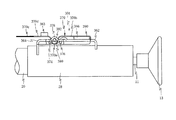
図13のステアリングコラム装置201は、円筒形状のステアリングコラム202と、このステアリングコラム202の内部を貫通するステアリングシャフト203と、このステアリングシャフト203の車両前後方向の後端に取り付けられて運転者から操舵力が作用されるステアリングホイール204と、ステアリングシャフト203の下端にユニバーサルジョイント205aを介して連結され、他端がユニバーサルジョイント205bを介してラック・ピニオン式のステアリングギヤ(図示せず)に連結されている中間シャフト206とを備えている。なお、ステアリングギヤには、タイロッド等を介して転舵輪(不図示)が連結されており、ステアリングホイール204を操舵することで転舵輪を転舵することができる。
(Second Embodiment)
Next, FIGS. 13 to 17 show an impact absorption type steering column apparatus according to a second embodiment of the present invention.
FIG. 13 is a diagram showing the shock absorbing steering column device of the second embodiment applied from the vehicle width direction to a vehicle steering device. 14 is a view taken along the line CC of FIG. FIG. 15 is a view showing a tilt mechanism of the present embodiment. FIG. 16 is a view taken along line DD in FIG. FIG. 17 is a diagram showing the shape of the energy absorbing member of the present embodiment.
A steering column device 201 shown in FIG. 13 is attached to a cylindrical steering column 202, a steering shaft 203 penetrating the inside of the steering column 202, and a rear end of the steering shaft 203 in the vehicle front-rear direction. A steering wheel 204 to which force is applied is connected to the lower end of the steering shaft 203 via a universal joint 205a, and the other end is connected to a rack and pinion type steering gear (not shown) via a universal joint 205b. And an intermediate shaft 206. A steered wheel (not shown) is connected to the steering gear via a tie rod or the like, and the steered wheel can be steered by steering the steering wheel 204.

ステアリングコラム202は、ステアリングシャフト203を軸受(図示せず)を介して回動自在に保持するインナコラム207と、インナコラム207が摺動自在に内嵌するアウタコラム208とで構成されている。そして、アウタコラム208は、ロアブラケット209及びチルト機構210を介して車体側部材211に支持されている。
図14は、図13のC−C線矢視を示す図であり、ロアブラケット209は、アウタコラム208の上部に車両前後方向に延在して固定されたボックス形状の部材であり、車両前後方向に延在する一対の側板209aに、長軸方向が車両前後方向に延在するように長孔209bが形成されている。また、車体側部材211には連結ブラケット212が固定されており、この連結ブラケット212に装着した係合ボルト213がロアブラケット209の長孔209bに挿通されることで、ロアブラケット209と連結ブラケット212とが連結されている。
The steering column 202 includes an inner column 207 that rotatably holds the steering shaft 203 via a bearing (not shown), and an outer column 208 in which the inner column 207 is slidably fitted. The outer column 208 is supported by the vehicle body side member 211 via the lower bracket 209 and the tilt mechanism 210.
FIG. 14 is a view taken along the line CC in FIG. 13, and the lower bracket 209 is a box-shaped member that extends and is fixed to the upper part of the outer column 208 in the vehicle front-rear direction. A long hole 209b is formed in the pair of side plates 209a extending in the direction so that the major axis direction extends in the vehicle front-rear direction. Further, a connecting bracket 212 is fixed to the vehicle body side member 211, and an engaging bolt 213 attached to the connecting bracket 212 is inserted into the long hole 209 b of the lower bracket 209, whereby the lower bracket 209 and the connecting bracket 212 are connected. And are connected.

そして、二次衝突時にステアリングホイール204から車両前後方向の前方に向けて強い力が加わると、ステアリングコラム202のアウタコラム208が車両前後方向の前方にストロークする。その際、アウタコラム208に固定されたロアブラケット209も車両前後方向の前方にストロークすると、車体側部材211に固定されている連結ブラケット212の係合ボルト213が、長孔209bの長軸方向にスライド移動することで、アウタコラム208の車両前後方向の前方のストロークをガイドする。   When a strong force is applied from the steering wheel 204 toward the front in the vehicle front-rear direction during a secondary collision, the outer column 208 of the steering column 202 strokes forward in the vehicle front-rear direction. At that time, when the lower bracket 209 fixed to the outer column 208 also strokes forward in the vehicle front-rear direction, the engagement bolt 213 of the connection bracket 212 fixed to the vehicle body side member 211 moves in the long axis direction of the long hole 209b. By sliding, the front stroke of the outer column 208 in the vehicle front-rear direction is guided.

チルト機構210は、図15に示すように、車体側部材211に固定された支持ブラケット230と、アウタコラム208に固定されて支持ブラケット230に対して昇降自在に、係合ボルト213を揺動中心として揺動自在に結合されている昇降ブラケット232と、支持ブラケット230及び昇降ブラケット232の間に装着したエネルギ吸収部材248とを備えているとともに、図16に示すように、支持ブラケット230に対する昇降ブラケット232の結合・解除動作を行なうチルト操作部233とを備えている。   As shown in FIG. 15, the tilt mechanism 210 includes a support bracket 230 fixed to the vehicle body side member 211 and a center of swinging of the engagement bolt 213 fixed to the outer column 208 and capable of moving up and down with respect to the support bracket 230. As shown in FIG. 16, the lifting bracket for the support bracket 230 is provided with a lifting bracket 232 that is swingably coupled to the support bracket 230 and an energy absorbing member 248 mounted between the lifting bracket 232. And a tilt operation unit 233 for performing the coupling / release operation of H.232.

支持ブラケット230は、図16に示すように、互いに車幅方向に離間しながら車体側部材211に固定され、車両上下方向の下方に延在している一対の支持板部234と、長軸が略車両上下方向に延在するように一対の支持板部234に形成されている長孔235とを備えている。
昇降ブラケット232は、図15及び図16に示すように、互いに車幅方向に平行に離間してアウタコラム208の下側に固定されており、支持ブラケット230の一対の支持板部234がそれぞれ当接する一対の当接板部236と、これら一対の当接板部236に車両前後方向の後方で開口しながら形成されている切り欠き237と、一対の当接板部236の下端同士に一体化されている底板部238から切り欠き237に対して車両前後方向の前方側で立ち上がっている係止板部239と、係止板部239の上部で車幅方向の一方及び他方に延在して設けられている吸収部材係合部240とを備えている。
As shown in FIG. 16, the support bracket 230 is fixed to the vehicle body side member 211 while being separated from each other in the vehicle width direction, and has a pair of support plate portions 234 extending downward in the vehicle vertical direction, And a long hole 235 formed in the pair of support plate portions 234 so as to extend substantially in the vehicle vertical direction.
As shown in FIGS. 15 and 16, the elevating bracket 232 is fixed to the lower side of the outer column 208 so as to be spaced apart from each other in the vehicle width direction, and the pair of support plate portions 234 of the support bracket 230 are respectively in contact with each other. A pair of contact plate portions 236 that are in contact with each other, a notch 237 that is formed in the pair of contact plate portions 236 while opening rearward in the vehicle front-rear direction, and a lower end of the pair of contact plate portions 236 are integrated with each other. A locking plate portion 239 that rises from the bottom plate portion 238 on the front side in the vehicle front-rear direction with respect to the notch 237, and extends to one and the other in the vehicle width direction above the locking plate portion 239. And an absorbing member engaging portion 240 provided.

また、チルト操作部233は、図16に示すように、昇降ブラケット232の切り欠き237及び支持ブラケット230の長孔235に挿通した頭部を有する円柱形状のチルトボルト242と、チルトボルト242の車幅方向の他方側の端部に螺合されているチルトナット244と、回転操作によりチルトナット244をチルトボルト242に締め付け、或いは緩めるチルトナット244と一体的に結合した操作レバー245とを備えている。そして、操作レバー245の反時計回りの回転によりチルトナット244を緩めると、チルトボルト242を支持ブラケット230の長孔235に沿って車両上下方向にスライドさせてステアリングコラム202の車両上下方向の位置を変更することができ、操作レバー245の時計回りの回転によりチルトナット244をチルトボルト242に締め付けることで、昇降ブラケット232が支持ブラケット230に結合されてステアリングコラム202の車両上下方向の位置が固定されるようになっている。   As shown in FIG. 16, the tilt operation unit 233 includes a columnar tilt bolt 242 having a head inserted through the notch 237 of the lifting bracket 232 and the long hole 235 of the support bracket 230, and a vehicle including the tilt bolt 242. A tilt nut 244 screwed to the other end portion in the width direction, and an operation lever 245 integrally coupled to the tilt nut 244 for tightening or loosening the tilt nut 244 to the tilt bolt 242 by a rotation operation are provided. Yes. Then, when the tilt nut 244 is loosened by the counterclockwise rotation of the operation lever 245, the tilt bolt 242 is slid in the vehicle vertical direction along the long hole 235 of the support bracket 230, and the position of the steering column 202 in the vehicle vertical direction is set. The tilt bracket 232 is coupled to the support bracket 230 by fixing the tilt nut 244 to the tilt bolt 242 by the clockwise rotation of the operation lever 245, and the vehicle vertical position of the steering column 202 is fixed. It has become so.

一方、支持ブラケット230と昇降ブラケット232との間に装着されているエネルギ吸収部材248は、断面形状が真円、楕円、多角形状からなる塑性変形自在な金属線(針金)の曲げ成形により形成されている。
このエネルギ吸収部材248は、図15及び図17に示すように、直線状の1本の金属線を折り曲げてコ字状に形成した基部248aと、この基部248aに対して平行に直線状に延在している一対の直線部248dと、基部248aと一対の直線部248dとの間で半円弧形状に形成されている一対の折り返し変形部248bと、一対の直線部248dから自由端まで直線に延在している符号248cで示した黒で塗りつぶした部分を備えている。この黒で塗りつぶした部分248cは、一対の直線部248d、基部248a及び一対の折り返し変形部248bと比較して、塑性変形する際の変形抵抗が変更されている。
On the other hand, the energy absorbing member 248 mounted between the support bracket 230 and the lifting bracket 232 is formed by bending a plastically deformable metal wire (wire) whose cross-sectional shape is a perfect circle, ellipse, or polygon. ing.
As shown in FIGS. 15 and 17, the energy absorbing member 248 includes a base portion 248a formed by bending a straight metal wire into a U shape, and linearly extending in parallel to the base portion 248a. A pair of existing straight portions 248d, a pair of folded deformation portions 248b formed in a semicircular arc shape between the base portion 248a and the pair of straight portions 248d, and a straight line from the pair of straight portions 248d to the free end A portion filled with black indicated by the extended reference numeral 248c is provided. Compared with the pair of straight portions 248d, the base portion 248a, and the pair of folded deformation portions 248b, the deformation resistance at the time of plastic deformation of the portion 248c filled with black is changed.

本実施形態では、符号248cの黒で塗りつぶした部分を、ショットピーニングにより加工硬化を施すことで塑性変形する際の変形抵抗を大きくした部分とし、変形抵抗増大部248cと称する。
上記構成のエネルギ吸収部材248は、図15で示すように、基部248aが昇降ブラケット232の係止板部239に掛け渡され、一対の折り返し変形部248bがチルトボルト242の車両前後方向の後方側の外周に掛け渡され、昇降ブラケット232の吸収部材係合部240と基部248aとの間にある一対の直線部248dが吸収部材係合部240に接触した状態で装着されている。ここで、エネルギ吸収部材248の一対の直線部248dの自由端は車両前後方向の前方を向いている。なお、図15では、基部248aは、係止板部239の車両前後方向の前方を向く面に当接して車幅方向に延在し、係止板部239の車幅方向の両端部から車両前後方向の後方に向けて折れ曲がって掛け渡されているが、係止板部239に車幅方向に離間して2つの貫通孔を形成し、基部248aの車両前後方向の後方に向けて折れ曲がった部位を、前記2つの貫通孔に通過させて掛け渡してもよい。また、基部248aと昇降ブラケット232の係止板部239とを溶接などで固着してもよい。
In the present embodiment, the portion of the reference numeral 248c painted in black is defined as a portion in which the deformation resistance at the time of plastic deformation is increased by performing work hardening by shot peening, and is referred to as a deformation resistance increasing portion 248c.
As shown in FIG. 15, the energy absorbing member 248 having the above configuration has a base portion 248 a spanned over a locking plate portion 239 of the lifting bracket 232, and a pair of folded deformation portions 248 b on the rear side of the tilt bolt 242 in the vehicle front-rear direction. A pair of linear portions 248d between the absorbing member engaging portion 240 and the base portion 248a of the lifting bracket 232 are mounted in contact with the absorbing member engaging portion 240. Here, the free ends of the pair of linear portions 248d of the energy absorbing member 248 face forward in the vehicle front-rear direction. In FIG. 15, the base portion 248 a extends in the vehicle width direction by contacting the front surface of the locking plate portion 239 facing in the vehicle front-rear direction and extends from both ends of the locking plate portion 239 in the vehicle width direction. Although bent over the rear in the front-rear direction, the hooking plate 239 is spaced apart in the vehicle width direction to form two through holes and bent toward the rear in the vehicle front-rear direction of the base 248a. The site may be passed through the two through holes. Further, the base portion 248a and the locking plate portion 239 of the lifting bracket 232 may be fixed by welding or the like.

ここで、請求項のステアリングコラムがアウタコラム208に対応し、請求項の移動部材が昇降ブラケット232に対応し、請求項の固定部材が係止板部239に対応し、請求項の扱き部材がチルトボルト242に対応し、請求項のストローク後半塑性領域が一対の変形抵抗増大部248cに対応し、請求項のストローク前半塑性領域が、基部248a,一対の折り返し変形部248b及び一対の直線部248dに対応する。   Here, the steering column of the claims corresponds to the outer column 208, the moving member of the claims corresponds to the lifting bracket 232, the fixing member of the claims corresponds to the locking plate portion 239, and the handling member of the claims Corresponding to the tilt bolt 242, the latter half stroke plastic region of the claims corresponds to the pair of deformation resistance increasing portions 248 c, and the first half stroke plastic region of the claims includes the base portion 248 a, the pair of folded deformation portions 248 b, and the pair of linear portions 248 d. Corresponding to

次に、本実施形態のステアリングコラム装置201の動作について説明する。
車両の衝突に伴って運転者がステアリングホイール204に二次衝突すると、ステアリングコラム202にはステアリングシャフト203を介して大きな衝撃荷重が加わる。
大きな衝撃荷重が加わったステアリングコラム202は、車両前後方向の前方にストロークして全長が縮まっていき、アウタコラム208は、車体側部材211に固定された連結ブラケット212にロアブラケット209がガイドされながら車両前後方向の前方にストロークし、昇降ブラケット232も、切り欠き247がチルトボルト242から離間していきながら車両前後方向の前方にストロークしていく。これに対して、車体側部材211に固定されている支持ブラケット230は、車両前後方向にストロークせず、そのままの位置に残る。
Next, the operation of the steering column device 201 of this embodiment will be described.
When the driver has a secondary collision with the steering wheel 204 due to the collision of the vehicle, a large impact load is applied to the steering column 202 via the steering shaft 203.
The steering column 202 to which a large impact load is applied strokes forward in the vehicle front-rear direction and the entire length is shortened, and the outer column 208 is guided by the connecting bracket 212 fixed to the vehicle body side member 211 while the lower bracket 209 is guided. The vehicle travels forward in the vehicle longitudinal direction, and the lifting bracket 232 also strokes forward in the vehicle longitudinal direction while the notch 247 moves away from the tilt bolt 242. On the other hand, the support bracket 230 fixed to the vehicle body side member 211 does not make a stroke in the vehicle front-rear direction and remains in the position as it is.

チルトボルト242は、支持ブラケット230とともに車両前後方向にストロークしないので、昇降ブラケット232の係止板部239に基部248aが掛け渡され、チルトボルト242の外周に折り返し変形部248bが掛け渡されているエネルギ吸収部材248は、基部248a側が車両前後方向の前方に引っ張られていく。
エネルギ吸収部材248の基部248a側が車両前後方向の前方に引っ張られると、基部248a、折り返し変形部248b及び一対の直線部248dがチルトボルト242に扱かれて塑性変形していき、一定の衝撃荷重が吸収されていく。
Since the tilt bolt 242 does not stroke in the vehicle front-rear direction together with the support bracket 230, the base portion 248 a is stretched over the locking plate portion 239 of the elevating bracket 232, and the folded deformation portion 248 b is stretched around the outer periphery of the tilt bolt 242. In the energy absorbing member 248, the base 248a side is pulled forward in the vehicle front-rear direction.
When the base portion 248a side of the energy absorbing member 248 is pulled forward in the vehicle front-rear direction, the base portion 248a, the folded-back deformation portion 248b, and the pair of linear portions 248d are handled by the tilt bolt 242 and plastically deformed, and a certain impact load is applied. It will be absorbed.

そして、さらにステアリングコラム202(アウタコラム208)がストローク後半である底着き位置に向かってストロークしていくと、加工硬化を施した変形抵抗増大部248cがチルトボルト242に扱かれて塑性変形していく。
このように、加工硬化を施した変形抵抗増大部248cが塑性変形すると、エネルギ吸収部材248の変形抵抗が増大して衝撃荷重を吸収する能力が増大するので、ステアリングコラム202(アウタコラム208)の底着き直前まで衝撃吸収荷重が緩やかに増加していくとともに、ステアリングコラム202(アウタコラム208)の底着きの際には、所定値以下の衝撃荷重吸収特性を得ることができる。
When the steering column 202 (outer column 208) further strokes toward the bottom position, which is the latter half of the stroke, the deformation resistance increasing portion 248c subjected to work hardening is handled by the tilt bolt 242 and plastically deformed. Go.
Thus, when the deformation resistance increasing portion 248c subjected to work hardening is plastically deformed, the deformation resistance of the energy absorbing member 248 increases and the ability to absorb impact load increases, so the steering column 202 (outer column 208) The shock absorbing load gradually increases until just before bottoming, and when the steering column 202 (outer column 208) is bottomed, a shock load absorbing characteristic of a predetermined value or less can be obtained.

したがって、ステアリングコラム202(アウタコラム208)の底着き直前まで衝撃吸収荷重が緩やかに増加していき、底着きの際には所定値以下の衝撃吸収荷重にすることができる。
また、本実施形態ではエネルギ吸収部材248を、金属線を折り曲げることにより構成し、昇降ブラケット232の係止板部239に基部248aを掛け渡し、チルトボルト242の外周に折り返し変形部248bを掛け渡すだけで、昇降ブラケット232とチルトボルト242との間に簡単に装着することができるので、組み立て作業の能率化を図ることができる。また、金属線を折り曲げることにより造られるエネルギ吸収部材248は、材料の無駄が殆ど生じないため、材料の歩留が向上する。また、エネルギ吸収部材248を加工する為に複雑な型を必要としない。したがって、製造コストの低減化を図ることができる。
Therefore, the shock absorbing load gradually increases until just before the steering column 202 (outer column 208) is bottomed, and the shock absorbing load below a predetermined value can be set at the bottom.
Further, in this embodiment, the energy absorbing member 248 is configured by bending a metal wire, the base 248a is hung on the locking plate 239 of the lifting bracket 232, and the folded deformation portion 248b is hung on the outer periphery of the tilt bolt 242. As a result, it can be easily mounted between the lifting bracket 232 and the tilt bolt 242, so that the assembly work can be made more efficient. In addition, since the energy absorbing member 248 made by bending the metal wire hardly wastes material, the yield of the material is improved. Further, a complicated mold is not required for processing the energy absorbing member 248. Therefore, the manufacturing cost can be reduced.

なお、本実施形態では、基部248aを昇降ブラケット232の係止板部239に掛け渡し、一対の折り返し変形部248bを、チルトボルト242の車両前後方向の後方側の外周に掛け渡し、一対の直線部248d及び変形抵抗増大部248cが車両前後方向の前方に延在するようにエネルギ吸収部材248を装着したが、本発明の要旨がこれに限定されるものではなく、例えば、基部248aをチルトボルト242に固定し、係止板部239側に曲面形状の凸部を設け、この凸部に一対の折り返し変形部248bを車両前後方向の前方側で掛け渡し、直線部248dが車両前後方向の後方に延在するようにエネルギ吸収部材248を装着すると、上述した第2実施形態と同様の効果を奏することができる。また、チルトボルト242は、横断面が真円の部材に限らず、横断面が六角形などの多角形状や、楕円形状であってもよい。   In the present embodiment, the base portion 248a is hung on the locking plate portion 239 of the lifting bracket 232, the pair of folded deformation portions 248b is hung on the outer periphery of the tilt bolt 242 in the vehicle front-rear direction, and a pair of straight lines The energy absorbing member 248 is mounted so that the portion 248d and the deformation resistance increasing portion 248c extend forward in the vehicle front-rear direction. However, the gist of the present invention is not limited to this, for example, the base portion 248a is attached to the tilt bolt. 242 is fixed, a curved convex part is provided on the locking plate part 239 side, a pair of folded deformation parts 248b are spanned on the convex part on the front side in the vehicle front-rear direction, and the straight part 248d is rearward in the vehicle front-rear direction When the energy absorbing member 248 is mounted so as to extend in the same manner, the same effect as in the second embodiment described above can be obtained. Further, the tilt bolt 242 is not limited to a member having a perfect circular cross section, and the cross section may be a polygonal shape such as a hexagon or an elliptical shape.

(第2実施形態のエネルギ吸収部材の第1変形例)
次に、図18に示すものは、図17で示したエネルギ吸収部材248と異なる第1変形例のエネルギ吸収部材である。この第1変形例のエネルギ吸収部材260は、熱処理を施した部材である。すなわち、直線状の1本の金属線を折り曲げてコ字状に形成した基部260aと、この基部260aに対して平行に直線状に延在している一対の直線部260dと、基部260aと一対の直線部260dとの間で半円弧形状に形成されている一対の折り返し変形部260bと、一対の直線部260dから自由端まで直線に延在している符号260cで示した黒で塗りつぶした部分を備えている。そして、一対の黒で塗りつぶしている部分260cと、一対の直線部260d、基部260a及び一対の折り返し変形部260bとの一方に熱処理を施すことで、黒で塗りつぶした部分260cが塑性変形する際の変形抵抗が、一対の直線部260d、基部260a及び一対の折り返し変形部260bと比較して変更されている。なお、一対の黒で塗りつぶした部分260cを一対の変形抵抗増大部260cと称する。
(First Modification of Energy Absorbing Member of Second Embodiment)
Next, what is shown in FIG. 18 is an energy absorbing member of a first modification different from the energy absorbing member 248 shown in FIG. The energy absorbing member 260 of the first modification is a member that has been subjected to heat treatment. That is, a base 260a formed by bending a straight metal wire into a U-shape, a pair of straight portions 260d extending linearly in parallel to the base 260a, and a pair of base 260a and a pair A pair of folded deformation portions 260b formed in a semicircular arc shape between the straight portion 260d and a portion filled with black indicated by reference numeral 260c extending straight from the pair of straight portions 260d to the free end It has. Then, by applying heat treatment to one of the pair of black portions 260c and the pair of straight portions 260d, the base portion 260a, and the pair of folded deformation portions 260b, the black portion 260c is subjected to plastic deformation. The deformation resistance is changed as compared with the pair of linear portions 260d, the base portion 260a, and the pair of folded deformation portions 260b. Note that the pair of black portions 260c are referred to as a pair of deformation resistance increasing portions 260c.

具体的には、一対の変形抵抗増大部260cに熱処理を施す場合には、焼入れ等のバルク熱処理により一対の変形抵抗増大部260cの内部を、一対の直線部260d、基部260a及び一対の折り返し変形部260bの内部と比較して硬くする方法や、浸炭、窒化、高周波焼入れ等のサーフェース熱処理により一対の変形抵抗増大部260cの表面を、一対の直線部260d、基部260a及び一対の折り返し変形部260bの表面と比較して硬くする方法が考えられる。また、一対の直線部260d、基部260a及び一対の折り返し変形部260bに熱処理を施す場合には、焼きなまし等のバルク熱処理により一対の直線部260d、基部260a及び一対の折り返し変形部260bの内部を一対の変形抵抗増大部260cの内部と比較して軟らかくする方法や、表面脱炭等のサーフェース熱処理により一対の直線部260d、基部260a及び一対の折り返し変形部260bの表面を一対の変形抵抗増大部260cの表面と比較して軟らかくする方法が考えられる。   Specifically, when the pair of deformation resistance increasing portions 260c is subjected to heat treatment, the inside of the pair of deformation resistance increasing portions 260c is subjected to bulk heat treatment such as quenching, the pair of linear portions 260d, the base portion 260a, and the pair of folded deformations. The surface of the pair of deformation resistance increasing portions 260c is made to be harder than the inside of the portion 260b by surface heat treatment such as carburizing, nitriding, induction hardening, etc., and the pair of linear portions 260d, the base portion 260a, and the pair of folded deformation portions A method of making it harder than the surface of 260b is conceivable. When heat treatment is performed on the pair of straight portions 260d, the base portion 260a, and the pair of folded deformation portions 260b, the inside of the pair of straight portions 260d, the base portion 260a, and the pair of folded deformation portions 260b is paired by bulk heat treatment such as annealing. The surface of the pair of straight portions 260d, the base portion 260a, and the pair of folded deformation portions 260b is made to be softer than the inside of the deformation resistance increase portion 260c or a surface heat treatment such as surface decarburization. A method of softening the surface of 260c is conceivable.

ここで、請求項のストローク後半塑性領域が一対の変形抵抗増大部260cに対応し、請求項のストローク前半塑性領域が、一対の直線部260d、基部260a及び一対の折り返し変形部260bに対応する。
上述した第1変形例のエネルギ吸収部材260を備えた衝撃吸収式ステアリングコラム装置201は、一対の変形抵抗増大部260cと、一対の直線部260d、基部260a及び一対の折り返し変形部260bとの一方に熱処理を施すことで、一対の変形抵抗増大部260cが塑性変形する際の変形抵抗が、一対の直線部260d、基部260a及び一対の折り返し変形部260bと比較して大きくなるように設定されているので、二次衝突時に、一対の変形抵抗増大部260cが塑性変形すると、エネルギ吸収部材260の変形抵抗が増大して衝撃荷重を吸収する能力が増大し、ステアリングコラム202(アウタコラム208)の底着き直前まで衝撃吸収荷重が緩やかに増加していくとともに、ステアリングコラム202(アウタコラム208)の底着きの際には、所定値以下の衝撃荷重吸収特性を得ることができる。
Here, the latter half stroke plastic region of the claims corresponds to the pair of deformation resistance increasing portions 260c, and the first stroke half plastic region of the claims corresponds to the pair of straight portions 260d, the base portion 260a, and the pair of folded deformation portions 260b.
The shock absorbing steering column device 201 provided with the energy absorbing member 260 of the first modification described above includes one of a pair of deformation resistance increasing portions 260c, a pair of linear portions 260d, a base portion 260a, and a pair of folded deformation portions 260b. By applying heat treatment, the deformation resistance when the pair of deformation resistance increasing portions 260c are plastically deformed is set to be larger than that of the pair of linear portions 260d, the base portion 260a, and the pair of folded deformation portions 260b. Therefore, when the pair of deformation resistance increasing portions 260c are plastically deformed at the time of the secondary collision, the deformation resistance of the energy absorbing member 260 is increased and the ability to absorb the impact load is increased, and the steering column 202 (outer column 208) of the steering column 202 is increased. The shock absorbing load gradually increases until just before the bottom reaches the steering column 202 (outer colla When the bottom arrive in 208), it is possible to obtain a shock load absorption characteristics of the predetermined value or less.

したがって、エネルギ吸収部材260の一対の変形抵抗増大部260cと、一対の直線部260d、基部260a及び一対の折り返し変形部260bとの一方に熱処理を施すことで、ステアリングコラム202(アウタコラム208)の底着き直前まで衝撃吸収荷重が緩やかに増加していき、底着きの際には所定値以下の衝撃吸収荷重に設定する衝撃荷重吸収特性を得ることができる。   Therefore, by applying heat treatment to one of the pair of deformation resistance increasing portions 260c of the energy absorbing member 260 and the pair of linear portions 260d, the base portion 260a, and the pair of folded deformation portions 260b, the steering column 202 (outer column 208) The shock absorbing load gradually increases until just before the bottoming, and the shock load absorbing characteristic set to a shock absorbing load equal to or less than a predetermined value can be obtained at the bottoming.

(第2実施形態のエネルギ吸収部材の第2変形例)
次に、図19に示すものは、図17で示したエネルギ吸収部材248と異なる第2変形例のエネルギ吸収部材である。
第2変形例のエネルギ吸収部材270は、直線状の1本の金属線を折り曲げてコ字状に形成した基部270aと、この基部270aに離間して延在している一対の直線部270dと、基部270aと一対の直線部270dとの間で半円弧形状に形成されている一対の折り返し変形部270bと、一対の直線部260dから自由端まで延在している黒で塗りつぶした一対の曲率部270cとを備えている。ここで、一対の曲率部270cは、基部270aに対して離間する方向に曲がって形成されている。
(Second modification of the energy absorbing member of the second embodiment)
Next, what is shown in FIG. 19 is an energy absorbing member of a second modification different from the energy absorbing member 248 shown in FIG.
The energy absorbing member 270 of the second modified example includes a base portion 270a formed by bending a straight metal wire into a U shape, and a pair of straight portions 270d extending apart from the base portion 270a. A pair of folded deformation portions 270b formed in a semicircular arc shape between the base portion 270a and the pair of straight portions 270d, and a pair of curvatures painted in black extending from the pair of straight portions 260d to the free ends Part 270c. Here, the pair of curvature portions 270c are formed to bend in a direction away from the base portion 270a.

ここで、請求項のストローク後半塑性領域が一対の曲率部270cに対応し、請求項のストローク前半塑性領域が、一対の直線部270d、基部270a及び一対の折り返し変形部270bに対応する。
この第2変形例のエネルギ吸収部材270を備えた衝撃吸収式ステアリングコラム装置201は、二次衝突時に、エネルギ吸収部材270の基部270a側が車両前後方向の前方に引っ張られると、一対の直線部270d、基部270a及び一対の折り返し変形部270bがチルトボルト242に扱かれて塑性変形していき、一定の衝撃荷重が吸収されていく。
Here, the latter half stroke plastic region of the claims corresponds to the pair of curvature portions 270c, and the first half stroke plastic region of the claims corresponds to the pair of straight portions 270d, the base portion 270a, and the pair of folded deformation portions 270b.
The shock absorbing steering column device 201 provided with the energy absorbing member 270 of the second modified example has a pair of linear portions 270d when the base 270a side of the energy absorbing member 270 is pulled forward in the vehicle longitudinal direction at the time of a secondary collision. The base portion 270a and the pair of folded deformation portions 270b are handled by the tilt bolts 242 and are plastically deformed, and a constant impact load is absorbed.

そして、さらにステアリングコラム202(アウタコラム208)がストローク後半である底着き位置に向かってストロークしていくと、一対の曲率部270cが吸収部材係合部240に矯正されて塑性変形するときの変形抵抗が増大していくことで、ステアリングコラム202(アウタコラム208)の底着き直前まで衝撃吸収荷重が緩やかに増加していき、底着きの際には所定値以下の衝撃吸収荷重に設定する衝撃荷重吸収特性を得ることができる。   Further, when the steering column 202 (outer column 208) further strokes toward the bottoming position, which is the latter half of the stroke, the pair of curvature portions 270c are corrected to the absorbing member engaging portion 240 and deformed when plastically deformed. As the resistance increases, the shock absorbing load gradually increases until just before the steering column 202 (outer column 208) bottoms out. When the bottom reaches the bottom, the shock absorbing load set to a predetermined value or less is set. Load absorption characteristics can be obtained.

(第2実施形態のエネルギ吸収部材の第3変形例)
次に、図20に示すものは、図17で示したエネルギ吸収部材248と異なる第3変形例のエネルギ吸収部材である。
第3変形例のエネルギ吸収部材280は、直線状の1本の金属線を折り曲げてコ字状に形成した基部280aと、この基部280aに対して平行に延在している一対の直線部280dと、基部280aと一対の直線部280dとの間で半円弧形状に形成されている一対の折り返し変形部280bと、一対の直線部280dから自由端まで延在している黒で塗りつぶした部分280cとを備えている。ここで、符号280cの部分は、一対の直線部280d、基部280a及び一対の折り返し変形部280bより断面積を大きくした大断面直線部280cとして形成されている。
(The 3rd modification of the energy absorption member of 2nd Embodiment)
Next, what is shown in FIG. 20 is an energy absorbing member of a third modification different from the energy absorbing member 248 shown in FIG.
The energy absorbing member 280 of the third modified example includes a base portion 280a formed by bending a straight metal wire into a U shape, and a pair of straight portions 280d extending in parallel to the base portion 280a. A pair of folded deformation portions 280b formed in a semicircular arc shape between the base portion 280a and the pair of straight portions 280d, and a black portion 280c extending from the pair of straight portions 280d to the free end. And. Here, the portion denoted by reference numeral 280c is formed as a large cross-sectional linear portion 280c having a cross-sectional area larger than that of the pair of linear portions 280d, the base portion 280a, and the pair of folded deformation portions 280b.

ここで、請求項のストローク後半塑性領域が一対の大断面直線部280cに対応し、請求項のストローク前半塑性領域が、一対の直線部280d、基部280a及び一対の折り返し変形部280bに対応する。
この第3変形例のエネルギ吸収部材280を備えた衝撃吸収式ステアリングコラム装置201は、二次衝突時に、エネルギ吸収部材280の基部280a側が車両前後方向の前方に引っ張られると、一対の直線部280d、基部280a及び一対の折り返し変形部280bがチルトボルト242に扱かれて塑性変形していき、一定の衝撃荷重が吸収されていく。
Here, the latter half stroke plastic region of the claims corresponds to the pair of large cross-sectional straight portions 280c, and the first stroke half plastic region of the claims corresponds to the pair of straight portions 280d, the base portion 280a, and the pair of folded deformation portions 280b.
In the impact absorption type steering column device 201 provided with the energy absorbing member 280 of the third modified example, when the base 280a side of the energy absorbing member 280 is pulled forward in the vehicle longitudinal direction at the time of a secondary collision, a pair of linear portions 280d. The base portion 280a and the pair of folded deformation portions 280b are handled by the tilt bolt 242 and are plastically deformed, and a constant impact load is absorbed.

そして、さらにステアリングコラム202(アウタコラム208)がストローク後半である底着き位置に向かってストロークしていくと、一対の大断面直線部280cがチルトボルト242に扱かれて塑性変形していく。
この際、一対の大断面直線部280cは、一対の直線部280d、基部280a及び一対の折り返し変形部280bに対して断面積が大きいので塑性変形する際の変形抵抗が増大し、衝撃荷重を吸収する能力が増大していく。
When the steering column 202 (outer column 208) further strokes toward the bottoming position, which is the latter half of the stroke, the pair of large cross-section linear portions 280c are handled by the tilt bolts 242 and are plastically deformed.
At this time, the pair of large cross-sectional straight portions 280c have a larger cross-sectional area than the pair of straight portions 280d, the base 280a, and the pair of folded deformation portions 280b, so that the deformation resistance at the time of plastic deformation increases and the impact load is absorbed. The ability to do increases.

したがって、エネルギ吸収部材280の一対の大断面直線部280cを、一対の直線部280d、基部280a及び一対の折り返し変形部280bと比較して断面積を大きくしたことで、ステアリングコラム202(アウタコラム208)の底着き直前まで衝撃吸収荷重が緩やかに増加していき、底着きの際には所定値以下の衝撃吸収荷重に設定する衝撃荷重吸収特性を得ることができる。   Therefore, the pair of large cross-sectional straight portions 280c of the energy absorbing member 280 are made larger in cross section than the pair of straight portions 280d, the base 280a, and the pair of folded deformation portions 280b, so that the steering column 202 (outer column 208). The shock absorbing load gradually increases until just before the bottoming), and an impact load absorbing characteristic set to a shock absorbing load of a predetermined value or less can be obtained at the bottoming.

ここで、直線部280dから断面積を徐々に大きくした状態で大断面直線部280cを形成すると、ステアリングコラム202のストローク後半の衝撃吸収荷重をさらに緩やかに増加させることができる。
なお、エネルギ吸収部材は、上述した第2実施形態のエネルギ吸収部材、第1変形例〜第3変形例の少なくとも2つを組み合わせた構成であってもよい。
Here, if the large cross-sectional straight portion 280c is formed in a state where the cross-sectional area is gradually increased from the straight portion 280d, the shock absorbing load in the second half of the stroke of the steering column 202 can be increased more gradually.
In addition, the structure which combined at least 2 of the energy absorption member of 2nd Embodiment mentioned above and a 1st modification-a 3rd modification may be sufficient as an energy absorption member.

(第3実施形態)
次に、図21から図23は、本発明に係る第3実施形態の衝撃吸収式ステアリングコラム装置を示すものである。なお、図1及び図2で示した構成と同一構成部分には、同一符号を付してその説明を省略する。
(Third embodiment)
Next, FIGS. 21 to 23 show an impact absorption type steering column apparatus according to a third embodiment of the present invention. In addition, the same code | symbol is attached | subjected to the component same as the structure shown in FIG.1 and FIG.2, and the description is abbreviate | omitted.

図21は、本実施形態の衝撃吸収式ステアリングコラム装置301を車両上下方向の上方から示した図である。図22は、本実施形態の衝撃吸収式ステアリングコラム装置301を車幅方向から示した図である。図23は、本実施形態のエネルギ吸収部材の形状を示す図である。   FIG. 21 is a diagram showing the shock absorbing steering column device 301 of the present embodiment as viewed from above in the vehicle vertical direction. FIG. 22 is a view showing the shock absorbing steering column device 301 of the present embodiment from the vehicle width direction. FIG. 23 is a diagram showing the shape of the energy absorbing member of the present embodiment.

本実施形態の衝撃吸収式ステアリングコラム装置301は、アウタコラム28の車両前後方向の後方側の外周に固定されている移動ブラケット362と、この移動ブラケット362の車幅方向に離間して設けた一対の取付板部364と、これら一対の取付板部364の車両前後方向の後端に装着されている一対の係止駒366と、これら一対の係止駒366を車体側部材(図示せず)に固定するボルト(図示せず)と、互いに車幅方向に離間しながら車両前後方向に延在して配置され、車両前後方向の後端が前記ボルトにより係止駒366を介して車体側部材(図示せず)に固定されているとともに、車両前後方向の前方側に、車両上下方向の下方に向けて山形に突出した部位を形成している一対のエネルギ吸収部材370と、一対の取付板部364の車両前後方向の前方側にそれぞれ形成した透孔372と、透孔372に対して車両前後方向の前方位置に形成した前側ガイド板部374と、透孔372に対して車両前後方向の後方位置に形成した後側ガイド板部376と、車両上下方向の上方に向けて山形に突出しながら透孔372に対して車両前後方向に横切るように取付板部364に固定した抑え板部378と、透孔372に対して車両前後方向に横切るように取付板部364に固定した受板部380と、エネルギ吸収部材370の一部が下側に通過するように配置しながら、抑え板部378及び受板部380の間で支持されているしごきピン382とを備えている。   The shock absorbing type steering column device 301 of the present embodiment includes a moving bracket 362 fixed to the outer periphery of the outer column 28 on the rear side in the vehicle front-rear direction and a pair of the moving bracket 362 provided in the vehicle width direction. Mounting plate portion 364, a pair of locking pieces 366 attached to the rear ends of the pair of mounting plate portions 364 in the vehicle front-rear direction, and the pair of locking pieces 366 as vehicle body side members (not shown). Bolts (not shown) that are fixed to the vehicle and extending in the vehicle front-rear direction while being spaced apart from each other in the vehicle width direction, the rear end in the vehicle front-rear direction is disposed on the vehicle body side member via the locking piece 366 by the bolts A pair of energy absorbing members 370 that are fixed to (not shown) and that form a portion projecting in a mountain shape downward in the vehicle vertical direction on the front side in the vehicle longitudinal direction, and a pair of mounting plates A through hole 372 formed on the front side in the vehicle front-rear direction of 364, a front guide plate portion 374 formed at a front position in the vehicle front-rear direction with respect to the through-hole 372, and a rear side in the vehicle front-rear direction with respect to the through-hole 372 A rear guide plate portion 376 formed at a position, a holding plate portion 378 fixed to the mounting plate portion 364 so as to cross the through hole 372 in the vehicle front-rear direction while projecting in a mountain shape upward in the vehicle vertical direction, The receiving plate portion 380 fixed to the mounting plate portion 364 so as to cross the through hole 372 in the vehicle longitudinal direction, and the holding plate portion 378 and the energy absorbing member 370 are disposed so as to pass downward. And ironing pins 382 supported between the receiving plate portions 380.

ここで、図22の符号383で示す部材は、エネルギ吸収部材370が衝撃荷重を吸収する際の上下移動を規制して衝撃吸収荷重の変動を抑制する規制部材であり、図示しない車体側部材に固定されている。
移動ブラケット362に形成した一対の取付板部364の車両前後方向の後端には、その位置で開口する切り欠き384が形成されている。そして、各切り欠き384の内側部分に、係止駒366が装着されている。
Here, the member denoted by reference numeral 383 in FIG. 22 is a regulating member that regulates the vertical movement when the energy absorbing member 370 absorbs the impact load and suppresses the fluctuation of the impact absorbing load. It is fixed.
A notch 384 is formed at the rear end of the pair of mounting plate portions 364 formed on the moving bracket 362 in the vehicle front-rear direction. A locking piece 366 is attached to the inner portion of each notch 384.

係止駒366は、アルミニウム合金等を材料として形成されており、通常はこの係止駒366に形成した小孔386と各取付板部364に形成され、この小孔386と整合する別の小孔とに掛け渡す様に充填された合成樹脂388により、各切り欠き384内に保持されている。ただし、二次衝突に伴う強い衝撃力が作用した場合には、合成樹脂388が剪断することで支持力を喪失し、各切り欠き384から車両前後方向の後方側に抜け出す。   The locking piece 366 is formed of an aluminum alloy or the like, and is normally formed in a small hole 386 formed in the locking piece 366 and each mounting plate portion 364, and another small hole aligned with the small hole 386. It is held in each notch 384 by a synthetic resin 388 filled so as to span the hole. However, when a strong impact force due to the secondary collision is applied, the synthetic resin 388 is sheared to lose the support force and come out from each notch 384 to the rear side in the vehicle front-rear direction.

また、エネルギ吸収部材370は、図23に示すように、板厚が均一の長尺な金属板を曲げ成形することにより屈曲部370aを形成した部材であって、長手方向を車両前後方向に向け、車両前後方向の後端側に形成した円孔390にボルトの下端部を挿通して車体側部材に支持されている。
すなわち、エネルギ吸収部材370は、屈曲部370aを間に位置して円孔390を形成した第1板状部370bと第2板状部370dとが形成されており、屈曲部370aから離間する方向に第2板状部370dから延在している黒で塗りつぶした部分370cを設けており、前記部分370cを、ショットピーニングにより加工硬化を施すことで塑性変形する際の変形抵抗を大きくした変形抵抗増大部370cとしている。
Further, as shown in FIG. 23, the energy absorbing member 370 is a member in which a bent portion 370a is formed by bending a long metal plate having a uniform thickness, and the longitudinal direction is directed in the vehicle longitudinal direction. The lower end portion of the bolt is inserted into a circular hole 390 formed on the rear end side in the vehicle front-rear direction and is supported by the vehicle body side member.
That is, the energy absorbing member 370 is formed with a first plate-like portion 370b and a second plate-like portion 370d in which a circular hole 390 is formed with the bent portion 370a interposed therebetween, and in a direction away from the bent portion 370a. Is provided with a portion 370c filled with black extending from the second plate-like portion 370d, and the portion 370c is subjected to work hardening by shot peening to increase the deformation resistance when plastically deformed. The increase part 370c is used.

一方、取付板部364に形成した透孔372の車両前後方向の前方に形成した前側ガイド板部374は、断面が四分の一円弧状で、その先端縁が車両上下方向の下方に向けて突出している。透孔372の車両前後方向の後方に形成した後側ガイド板部376は、断面が略倒立U字形で、その先端縁が車両上下方向の下方に向けて突出している。
抑え板部378は下面を円弧状凹面としており、受板部380は上面を円弧状凹面としている。そして、これら抑え板部378の下面と受板部380の上面との間で、しごきピン382の両端部を支持している。従って、各しごきピン382は、それぞれ透孔372の車両前後方向の中央部を幅方向に亙って横切る状態で支持されている。この状態で各しごきピン382の下面は、受板部380の上面よりも車両上下方向の上方に位置する。
On the other hand, the front guide plate portion 374 formed on the front side in the vehicle front-rear direction of the through hole 372 formed in the mounting plate portion 364 has a quarter-arc cross section and its leading edge faces downward in the vehicle vertical direction. It protrudes. The rear guide plate portion 376 formed at the rear of the through-hole 372 in the vehicle front-rear direction has a substantially inverted U-shaped cross section, and the leading edge protrudes downward in the vehicle vertical direction.
The holding plate portion 378 has an arc-shaped concave surface on the lower surface, and the receiving plate portion 380 has an arc-shaped concave surface on the upper surface. The both ends of the ironing pin 382 are supported between the lower surface of the holding plate portion 378 and the upper surface of the receiving plate portion 380. Accordingly, each ironing pin 382 is supported in a state of crossing the center portion of the through hole 372 in the vehicle front-rear direction across the width direction. In this state, the lower surface of each ironing pin 382 is located above the upper surface of the receiving plate portion 380 in the vehicle vertical direction.

ここで、請求項のステアリングコラムがアウタコラム28に対応し、請求項の移動部材が前側ガイド板部374及び後側ガイド板部376に対応し、請求項の固定部材がエネルギ吸収部材370を車体側部材に固定しているボルトに対応し、請求項の扱き部材がしごきピン382に対応し、請求項のストローク後半塑性領域が変形抵抗増大部370cに対応し、請求項のストローク前半塑性領域が、屈曲部370a及び第2板状部370dに対応する。   Here, the steering column of the claims corresponds to the outer column 28, the moving member of the claims corresponds to the front guide plate portion 374 and the rear guide plate portion 376, and the fixing member of the claims sets the energy absorbing member 370 to the vehicle body. Corresponding to the bolt fixed to the side member, the handling member of the claim corresponds to the ironing pin 382, the latter half stroke plastic region of the claim corresponds to the deformation resistance increasing portion 370c, the pre-stroke half plastic region of the claim is , Corresponding to the bent portion 370a and the second plate-like portion 370d.

本実施形態の衝撃吸収式ステアリングコラム装置301は、衝突事故の際に以下のように作用して、ステアリングホイール13にぶつかった運転者の身体に加わる衝撃を緩和する。
二次衝突時には移動ブラケット362が、アウタコラム28とともに車両前後方向の前方に変位する。これに対して、係止駒366を車体側部材22に固定しているボルトは、そのままの位置に残る。
The shock absorption type steering column device 301 of the present embodiment acts as follows in the event of a collision accident, and alleviates the impact applied to the driver's body that hits the steering wheel 13.
At the time of the secondary collision, the moving bracket 362 is displaced forward in the vehicle longitudinal direction together with the outer column 28. On the other hand, the bolt that fixes the locking piece 366 to the vehicle body side member 22 remains in its position.

これにより、その車両前後方向の後端をボルトで固定されているエネルギ吸収部材370も車両前後方向の前方に変位することなく、そのままの位置で支持される。
エネルギ吸収部材370がそのままの位置で支持された状態で、移動ブラケット362が車両前後方向の前方にストロークするので、屈曲部370a及び第2板状部370dは、車体側部材に固定されている規制部材383によりあばれ(上下移動)が規制されながら、前側ガイド板部374及び後側ガイド板部376としごきピン382の下面との間で扱かれながら車両前後方向の前方に変位する。このように、エネルギ吸収部材370の屈曲部370a及び第2板状部370dが塑性変形していくことで、一定の衝撃荷重が吸収されていく。
Thereby, the energy absorbing member 370 whose rear end in the vehicle front-rear direction is fixed by the bolt is also supported at the position without being displaced forward in the vehicle front-rear direction.
Since the moving bracket 362 strokes forward in the vehicle front-rear direction while the energy absorbing member 370 is supported as it is, the bent portion 370a and the second plate-like portion 370d are regulated to be fixed to the vehicle body side member. While the play (up and down movement) is restricted by the member 383, the member 383 is moved forward in the vehicle longitudinal direction while being handled between the front guide plate portion 374 and the rear guide plate portion 376 and the lower surface of the ironing pin 382. As described above, the bent portion 370a and the second plate-like portion 370d of the energy absorbing member 370 are plastically deformed, so that a constant impact load is absorbed.

そして、さらに移動ブラケット362がストローク後半である底着き位置まで車両前後方向の前方にストロークしていくと、加工硬化を施した変形抵抗増大部370cが、車体側部材に固定されている規制部材383によってあばれ(上下移動)が規制されながら、前側ガイド板部374及び後側ガイド板部376としごきピン382の下面との間で扱かれて塑性変形していく。   When the moving bracket 362 further strokes forward in the vehicle front-rear direction to the bottom position, which is the latter half of the stroke, the deformation resistance increasing portion 370c subjected to work hardening is restricted to the regulating member 383 fixed to the vehicle body side member. As a result, the front guide plate portion 374 and the rear guide plate portion 376 are handled between the lower surface of the ironing pin 382 and are plastically deformed.

このように、加工硬化を施した変形抵抗増大部370cが塑性変形すると、エネルギ吸収部材370の変形抵抗が増大して衝撃荷重を吸収する能力が増大するので、ステアリングコラム(アウタコラム28)の底着き直前まで衝撃吸収荷重が緩やかに増加していくとともに、ステアリングコラムの底着きの際には、所定値以下の衝撃荷重吸収特性を得ることができる。   Thus, when the deformation resistance increasing portion 370c subjected to work hardening is plastically deformed, the deformation resistance of the energy absorbing member 370 increases and the ability to absorb the impact load increases, so that the bottom of the steering column (outer column 28) is increased. The shock absorbing load gradually increases until just before arrival, and when the steering column is bottomed, an impact load absorbing characteristic of a predetermined value or less can be obtained.

したがって、ステアリングコラムの底着き直前まで衝撃吸収荷重が緩やかに増加していき、底着きの際には所定値以下の衝撃吸収荷重にすることができる。   Therefore, the shock absorbing load gradually increases until just before the steering column bottoms, and the shock absorbing load below a predetermined value can be obtained at the bottom.

(第3実施形態のエネルギ吸収部材の第1変形例)
次に、図24に示すものは、図23で示したエネルギ吸収部材370と異なる第1変形例のエネルギ吸収部材である。この第1変形例のエネルギ吸収部材400は、熱処理を施した部材である。
(First Modification of Energy Absorbing Member of Third Embodiment)
Next, what is shown in FIG. 24 is an energy absorbing member of a first modification different from the energy absorbing member 370 shown in FIG. The energy absorbing member 400 of the first modification is a member that has been subjected to heat treatment.

すなわち、エネルギ吸収部材400は、屈曲部400aを間に位置して円孔404を形成した第1板状部400bと第2板状部400dとが形成されており、屈曲部400aから離間する方向に第2板状部400dから延在している黒で塗りつぶした部分400cを設けており、この部分400cを、屈曲部400a及び第2板状部400dと比較して、塑性変形する際の変形抵抗が大きくなるように設定している。   That is, the energy absorbing member 400 is formed with a first plate-like portion 400b and a second plate-like portion 400d in which a circular hole 404 is formed with the bent portion 400a interposed therebetween, and in a direction away from the bent portion 400a. A portion 400c filled with black extending from the second plate-like portion 400d is provided, and the portion 400c is deformed when plastically deformed as compared with the bent portion 400a and the second plate-like portion 400d. The resistance is set to be large.

具体的には、変形抵抗増大部400cに熱処理を施す場合には、焼入れ等のバルク熱処理により変形抵抗増大部400cの内部を、屈曲部400a及び第2板状部400dの内部と比較して硬くする方法や、浸炭、窒化、高周波焼入れ等のサーフェース熱処理により変形抵抗増大部400cの表面を屈曲部400a及び第2板状部400dの表面と比較して硬くする方法が考えられる。また、屈曲部400a及び第2板状部400dに熱処理を施す場合には、焼きなまし等のバルク熱処理により屈曲部400a及び第2板状部400dの内部を変形抵抗増大部400cの内部と比較して軟らかくする方法や、表面脱炭等のサーフェース熱処理により屈曲部400a及び第2板状部400dの表面を変形抵抗増大部400cの表面と比較して軟らかくする方法が考えられる。   Specifically, when heat treatment is performed on the deformation resistance increasing portion 400c, the inside of the deformation resistance increasing portion 400c is hardened by bulk heat treatment such as quenching as compared with the inside of the bent portion 400a and the second plate-shaped portion 400d. And a method of making the surface of the deformation resistance increasing portion 400c harder than the surfaces of the bent portion 400a and the second plate-like portion 400d by surface heat treatment such as carburizing, nitriding, and induction hardening. Further, when heat-treating the bent portion 400a and the second plate-like portion 400d, the inside of the bent portion 400a and the second plate-like portion 400d is compared with the inside of the deformation resistance increasing portion 400c by bulk heat treatment such as annealing. A method of softening or a method of softening the surface of the bent portion 400a and the second plate-like portion 400d by the surface heat treatment such as surface decarburization as compared with the surface of the deformation resistance increasing portion 400c can be considered.

ここで、請求項のストローク後半塑性領域が変形抵抗増大部400cに対応し、請求項のストローク前半塑性領域が、屈曲部400a及び第2板状部400dに対応する。
上述した第1変形例のエネルギ吸収部材400を備えた衝撃吸収式ステアリングコラム装置201は、一対の変形抵抗増大部400cと、屈曲部400a及び第2板状部400dとの一方に熱処理を施すことで、車体側部材に固定されている規制部材383によってあばれ(上下移動)が規制されながら一対の変形抵抗増大部400cが塑性変形する際の変形抵抗が、屈曲部400a及び第2板状部400dと比較して大きくなるように設定されているので、二次衝突時に、一対の変形抵抗増大部400cが塑性変形すると、エネルギ吸収部材400の変形抵抗が増大して衝撃荷重を吸収する能力が増大し、ステアリングコラム(アウタコラム208)の底着き直前まで衝撃吸収荷重が緩やかに増加していくとともに、ステアリングコラム(アウタコラム208)の底着きの際には、所定値以下の衝撃荷重吸収特性を得ることができる。
Here, the latter half stroke plastic region of the claims corresponds to the deformation resistance increasing portion 400c, and the first half stroke plastic region of the claims corresponds to the bent portion 400a and the second plate-like portion 400d.
The shock absorbing steering column device 201 including the energy absorbing member 400 of the first modification described above performs heat treatment on one of the pair of deformation resistance increasing portions 400c, the bent portion 400a, and the second plate-like portion 400d. Thus, the deformation resistance when the pair of deformation resistance increasing portions 400c are plastically deformed while the displacement (up and down movement) is restricted by the restriction member 383 fixed to the vehicle body side member is the bending portion 400a and the second plate-like portion 400d. Therefore, when the pair of deformation resistance increasing portions 400c are plastically deformed during a secondary collision, the deformation resistance of the energy absorbing member 400 is increased and the ability to absorb the impact load is increased. The shock absorbing load gradually increases until just before the steering column (outer column 208) bottoms, and the steering column ( When the bottom arrive in Utakoramu 208) she can be obtained an impact load absorption characteristics of the predetermined value or less.

したがって、変形抵抗増大部400cと、屈曲部400a及び第2板状部400dとの一方に熱処理を施すことで、ステアリングコラム(アウタコラム208)の底着き直前まで衝撃吸収荷重が緩やかに増加していき、底着きの際には所定値以下の衝撃吸収荷重に設定する衝撃荷重吸収特性を得ることができる。   Therefore, by applying heat treatment to one of the deformation resistance increasing portion 400c, the bent portion 400a, and the second plate-like portion 400d, the shock absorbing load gradually increases until just before the steering column (outer column 208) reaches the bottom. In the case of bottoming, it is possible to obtain an impact load absorption characteristic set to an impact absorption load of a predetermined value or less.

(第3実施形態のエネルギ吸収部材の第2変形例)
次に、図25に示すものは、図23で示したエネルギ吸収部材370と異なる第2変形例のエネルギ吸収部材である。
第2変形例のエネルギ吸収部材410は、屈曲部410aを間に位置して円孔414を形成した第1板状部410bと第2板状部410dとが形成されており、屈曲部410aから離間する方向に第2板状部410dから延在している黒で塗りつぶした部分410cを設けており、この部分410cは、自由端に向かうに従い屈曲部410aから離間する方向に曲がっている変形抵抗増大部410cとされている。
(Second modification of the energy absorbing member of the third embodiment)
Next, what is shown in FIG. 25 is an energy absorbing member of a second modification different from the energy absorbing member 370 shown in FIG.
The energy absorbing member 410 of the second modified example is formed with a first plate-like portion 410b and a second plate-like portion 410d in which a circular hole 414 is formed with the bent portion 410a interposed therebetween, from the bent portion 410a. A portion 410c filled with black extending from the second plate-like portion 410d is provided in a direction away from the second plate-like portion 410d, and the portion 410c is deformed to be bent in a direction away from the bent portion 410a toward the free end. The increase part 410c is used.

ここで、請求項のストローク後半塑性領域が変形抵抗増大部410cに対応し、請求項のストローク前半塑性領域が、屈曲部410a及び第2板状部410dに対応する。
この第2変形例のエネルギ吸収部材410を備えた衝撃吸収式ステアリングコラム装置301は、二次衝突時に、移動ブラケット362が車両前後方向の前方にストロークすると、エネルギ吸収部材410の屈曲部410a及び第2板状部410dが、車体側部材に固定されている規制部材383によってあばれ(上下移動)が規制されながら、前側ガイド板部374及び後側ガイド板部376としごきピン382の下面との間で扱かれながら車両前後方向の前方に変位する。このように、エネルギ吸収部材410の屈曲部410a及び第2板状部410dが塑性変形していくことで、一定の衝撃荷重が吸収されていく。
Here, the latter half stroke plastic region in the claims corresponds to the deformation resistance increasing portion 410c, and the first half stroke plastic region in the claims corresponds to the bent portion 410a and the second plate-like portion 410d.
The shock absorbing type steering column device 301 provided with the energy absorbing member 410 of the second modified example has the bent portion 410a of the energy absorbing member 410 and the second portion when the moving bracket 362 strokes forward in the vehicle longitudinal direction at the time of a secondary collision. While the two plate-like portions 410d are restricted (up and down movement) by the restricting member 383 fixed to the vehicle body side member, the front plate portion 374 and the rear guide plate portion 376 and the lower surface of the ironing pin 382 are restricted. Displaces forward in the longitudinal direction of the vehicle while being handled. As described above, the bent portion 410a and the second plate-like portion 410d of the energy absorbing member 410 are plastically deformed, so that a constant impact load is absorbed.

そして、さらに移動ブラケット362がストローク後半である底着き位置まで車両前後方向の前方にストロークしていくと、自由端に向かうに従い曲がって形成されている変形抵抗増大部410cが、車体側部材に固定されている規制部材383によってあばれ(上下移動)を規制する、と同時に規制部材383により変形抵抗増大部410cが矯正されて塑性変形するときの変形抵抗が増大していく。   When the moving bracket 362 further strokes forward in the front-rear direction of the vehicle to the bottom position, which is the latter half of the stroke, the deformation resistance increasing portion 410c that is bent toward the free end is fixed to the vehicle body side member. When the restriction member 383 is used to restrict play (up and down movement), the deformation resistance when the deformation resistance increasing portion 410c is corrected and plastically deformed by the restriction member 383 increases.

これにより、ステアリングコラム(アウタコラム28)の底着き直前まで衝撃吸収荷重が緩やかに増加していくとともに、ステアリングコラムの底着きの際には、所定値以下の衝撃荷重吸収特性を得ることができる。
したがって、ステアリングコラムの底着き直前まで衝撃吸収荷重が緩やかに増加していき、底着きの際には所定値以下の衝撃吸収荷重にすることができる。
As a result, the shock absorption load gradually increases until just before the steering column (outer column 28) bottoms, and when the steering column bottoms, an impact load absorption characteristic of a predetermined value or less can be obtained. .
Therefore, the shock absorbing load gradually increases until just before the steering column bottoms, and the shock absorbing load below a predetermined value can be obtained at the bottom.

(第3実施形態のエネルギ吸収部材の第3変形例)
次に、図26に示すものは、図23で示したエネルギ吸収部材370と異なる第3変形例のエネルギ吸収部材である。
第3変形例のエネルギ吸収部材420は、屈曲部420aを間に位置して円孔424を形成した第1板状部420bと第2板状部420dとが形成されており、屈曲部420aから離間する方向に第2板状部420dから延在している黒で塗りつぶした部分420cを設けており、この部分420cは、屈曲部420a及び第2板状部420dと比較して肉厚を増大させた厚肉部420cとされている。
(The 3rd modification of the energy absorption member of 3rd Embodiment)
Next, what is shown in FIG. 26 is an energy absorbing member of a third modification different from the energy absorbing member 370 shown in FIG.
The energy absorbing member 420 of the third modified example is formed with a first plate-like portion 420b and a second plate-like portion 420d in which a circular hole 424 is formed with the bent portion 420a interposed therebetween, from the bent portion 420a. A portion 420c filled with black extending from the second plate-shaped portion 420d is provided in the separating direction, and this portion 420c has an increased thickness compared to the bent portion 420a and the second plate-shaped portion 420d. The thick portion 420c is made to be.

ここで、請求項のストローク後半塑性領域が厚肉部420cに対応し、請求項のストローク前半塑性領域が、屈曲部420a及び第2板状部420dに対応する。
この第3変形例のエネルギ吸収部材420を備えた衝撃吸収式ステアリングコラム装置301は、二次衝突時に、移動ブラケット362が車両前後方向の前方にストロークすると、エネルギ吸収部材420の屈曲部420a及び第2板状部420dが、車体側部材に固定されている規制部材383によってあばれ(上下移動)が規制されながら、前側ガイド板部374及び後側ガイド板部376としごきピン382の下面との間で扱かれて車両前後方向の前方に変位する。このように、エネルギ吸収部材420の屈曲部420a及び第2板状部420dが塑性変形していくことで、一定の衝撃荷重が吸収されていく。
Here, the latter half stroke plastic region of the claims corresponds to the thick portion 420c, and the first half stroke plastic region of the claims corresponds to the bent portion 420a and the second plate-like portion 420d.
The shock absorbing steering column device 301 provided with the energy absorbing member 420 of the third modified example has the bent portion 420a and the second portion of the energy absorbing member 420 when the moving bracket 362 strokes forward in the vehicle longitudinal direction at the time of a secondary collision. While the two plate-like portions 420d are restricted (up and down movement) by the restricting member 383 fixed to the vehicle body side member, the front plate portion 374 and the rear guide plate portion 376 and the lower surface of the ironing pin 382 are restricted. Displaced forward in the vehicle longitudinal direction. Thus, a constant impact load is absorbed by the plastic deformation of the bent portion 420a and the second plate-like portion 420d of the energy absorbing member 420.

そして、さらに移動ブラケット362がストローク後半である底着き位置まで車両前後方向の前方にストロークしていくと、肉厚を増大させた厚肉部420cが、車体側部材に固定されている規制部材383によってあばれ(上下移動)が規制されながら前側ガイド板部374及び後側ガイド板部376としごきピン382の下面との間で扱かれて塑性変形していく。   When the moving bracket 362 further strokes forward in the vehicle front-rear direction to the bottom position, which is the latter half of the stroke, the thickened portion 420c having the increased thickness is fixed to the vehicle body side member. As a result, the front guide plate portion 374 and the rear guide plate portion 376 and the lower surface of the ironing pin 382 are handled and plastically deformed while the play (up and down movement) is restricted.

このように、肉厚を増大させた厚肉部420cが塑性変形すると、エネルギ吸収部材420の変形抵抗が増大して衝撃荷重を吸収する能力が増大するので、ステアリングコラム(アウタコラム28)の底着き直前まで衝撃吸収荷重が緩やかに増加していくとともに、ステアリングコラムの底着きの際には、所定値以下の衝撃荷重吸収特性を得ることができる。   As described above, when the thick portion 420c having the increased thickness is plastically deformed, the deformation resistance of the energy absorbing member 420 is increased and the ability to absorb the impact load is increased, so that the bottom of the steering column (outer column 28) is increased. The shock absorbing load gradually increases until just before arrival, and when the steering column is bottomed, an impact load absorbing characteristic of a predetermined value or less can be obtained.

したがって、ステアリングコラム(アウタコラム28)の底着き直前まで衝撃吸収荷重が緩やかに増加していき、底着きの際には所定値以下の衝撃吸収荷重にすることができる。
ここで、第2板状部420dから断面積を徐々に大きくした状態で厚肉部420cを形成すると、ステアリングコラムのストローク後半の衝撃吸収荷重をさらに緩やかに増加させることができる。
なお、エネルギ吸収部材は、上述した第3実施形態のエネルギ吸収部材、第1変形例〜第3変形例の少なくとも2つを組み合わせた構成であってもよい。
Therefore, the shock absorbing load gradually increases until just before the steering column (outer column 28) is bottomed, and when the bottom is settled, the shock absorbing load can be set to a predetermined value or less.
Here, if the thick portion 420c is formed in a state where the cross-sectional area is gradually increased from the second plate-shaped portion 420d, the shock absorbing load in the latter half of the stroke of the steering column can be increased more gradually.
In addition, the structure which combined at least 2 of the energy absorption member of 3rd Embodiment mentioned above and a 1st modification-a 3rd modification may be sufficient as an energy absorption member.

(第3実施形態のエネルギ吸収部材の第4変形例)
さらに、図27に示すものは、図23で示したエネルギ吸収部材370と異なる第3変形例のエネルギ吸収部材である。
第4変形例のエネルギ吸収部材430は、板厚が均一の長尺な金属板を曲げ成形することにより屈曲部430aを形成した部材であって、屈曲部430aを間に位置して円孔434を形成した第1板状部430bと第2板状部430dとが形成されており、第2板状部430dの端部側に、第2板状部430dと板厚が同一で、端部に向かうに従いエネルギ吸収部材430の板幅を徐々に増大させる変形抵抗増大部430cが一体に固定されている。
(Fourth modification of the energy absorbing member of the third embodiment)
Further, what is shown in FIG. 27 is an energy absorbing member of a third modified example different from the energy absorbing member 370 shown in FIG.
The energy absorbing member 430 of the fourth modification is a member in which a bent portion 430a is formed by bending a long metal plate having a uniform thickness, and the circular hole 434 is positioned with the bent portion 430a interposed therebetween. The first plate-like portion 430b and the second plate-like portion 430d are formed, and the end portion of the second plate-like portion 430d has the same plate thickness as the second plate-like portion 430d, and the end portion. A deformation resistance increasing portion 430c that gradually increases the plate width of the energy absorbing member 430 as it goes is fixed integrally.

ここで、請求項のストローク後半塑性領域が、変形抵抗増大部430cを固定した第2板状部430dの端部側に対応し、請求項のストローク前半塑性領域が、屈曲部430a及び変形抵抗増大部430cを固定していない第2板状部430dに対応する。
この第4変形例のエネルギ吸収部材430を備えた衝撃吸収式ステアリングコラム装置301は、二次衝突時に、移動ブラケット362が車両前後方向の前方にストロークすると、エネルギ吸収部材420の屈曲部430a及び変形抵抗増大部430cを固定していない第2板状部430dが、車体側部材に固定されている規制部材383によってあばれ(上下移動)が規制されながら、前側ガイド板部374及び後側ガイド板部376としごきピン382の下面との間で扱かれながら車両前後方向の前方に変位する。このように、エネルギ吸収部材430の屈曲部430a及び変形抵抗増大部430cを固定していない第2板状部430dが塑性変形していくことで、一定の衝撃荷重が吸収されていく。
Here, the latter half stroke plastic region of the claims corresponds to the end side of the second plate-like portion 430d to which the deformation resistance increasing portion 430c is fixed, and the first stroke half plastic region of the claims is the bent portion 430a and the deformation resistance increasing. This corresponds to the second plate-like portion 430d where the portion 430c is not fixed.
The shock absorbing type steering column device 301 provided with the energy absorbing member 430 of the fourth modified example has a bent portion 430a and deformation of the energy absorbing member 420 when the moving bracket 362 strokes forward in the vehicle front-rear direction at the time of a secondary collision. While the second plate-like portion 430d not fixing the resistance increasing portion 430c is restricted from being moved (moved up and down) by a restriction member 383 fixed to the vehicle body side member, the front guide plate portion 374 and the rear guide plate portion While being handled between 376 and the lower surface of the ironing pin 382, it is displaced forward in the vehicle longitudinal direction. Thus, a constant impact load is absorbed by the plastic deformation of the second plate-shaped portion 430d that does not fix the bent portion 430a and the deformation resistance increasing portion 430c of the energy absorbing member 430.

そして、さらに移動ブラケット362がストローク後半である底着き位置まで車両前後方向の前方にストロークしていくと、変形抵抗増大部430cを固定した第2板状部430dの端部側が、車体側部材に固定されている規制部材383によってあばれ(上下移動)が規制されながら、前側ガイド板部374及び後側ガイド板部376としごきピン382の下面との間で扱かれて塑性変形していく。   When the moving bracket 362 further strokes forward in the vehicle front-rear direction to the bottom position, which is the latter half of the stroke, the end side of the second plate-like portion 430d to which the deformation resistance increasing portion 430c is fixed becomes the vehicle body side member. While the play (up-and-down movement) is restricted by the fixed restriction member 383, it is handled between the front guide plate portion 374 and the rear guide plate portion 376 and the lower surface of the ironing pin 382 and plastically deforms.

このように、エネルギ吸収部材430の変形抵抗増大部430cを固定した第2板状部430dの端部側が塑性変形すると、エネルギ吸収部材430の変形抵抗が増大して衝撃荷重を吸収する能力が増大するので、ステアリングコラム(アウタコラム28)の底着き直前まで衝撃吸収荷重が緩やかに増加していくとともに、ステアリングコラムの底着きの際には、所定値以下の衝撃荷重吸収特性を得ることができる。   As described above, when the end portion side of the second plate-like portion 430d to which the deformation resistance increasing portion 430c of the energy absorbing member 430 is fixed is plastically deformed, the deformation resistance of the energy absorbing member 430 increases and the ability to absorb the impact load increases. Therefore, the shock absorbing load gradually increases until just before the steering column (outer column 28) bottoms, and when the steering column bottoms, an impact load absorbing characteristic of a predetermined value or less can be obtained. .

したがって、ステアリングコラムの底着き直前まで衝撃吸収荷重が緩やかに増加していき、底着きの際には所定値以下の衝撃吸収荷重にすることができる。
なお、本実施形態の変形抵抗増大部430cは、長手方向の他端側に向かうに従いエネルギ吸収部材430の板幅を徐々に増大させる形状として固定されているが、長手方向の他端側に向かって一定の幅で固定されていてもよい。
Therefore, the shock absorbing load gradually increases until just before the steering column bottoms, and the shock absorbing load below a predetermined value can be obtained at the bottom.
Note that the deformation resistance increasing portion 430c of the present embodiment is fixed in a shape that gradually increases the plate width of the energy absorbing member 430 toward the other end side in the longitudinal direction, but is directed toward the other end side in the longitudinal direction. And may be fixed at a certain width.

また、第3実施形態において、第2変形例のエネルギ吸収部材410(図25参照)以外は、あばれを規制する規制部材383が車体側部材に配置されていてもよいし、配置されていなくてもよい。   Further, in the third embodiment, except for the energy absorbing member 410 (see FIG. 25) of the second modified example, the regulating member 383 that regulates play may or may not be disposed on the vehicle body side member. Also good.

本発明に係る衝撃吸収式ステアリングコラム装置を搭載した自動車の操舵機構部の概略図である。It is the schematic of the steering mechanism part of the motor vehicle carrying the shock absorption type steering column apparatus which concerns on this invention. 本発明に係る第1実施形態の衝撃吸収式ステアリングコラム装置を車幅方向から示した図である。It is the figure which showed the shock absorption type steering column apparatus of 1st Embodiment which concerns on this invention from the vehicle width direction. 図2のA−A線矢視図である。It is an AA arrow directional view of FIG. 図2のB−B線矢視図である。It is a BB line arrow directional view of FIG. 第1実施形態のエネルギ吸収部材を示す図である。It is a figure which shows the energy absorption member of 1st Embodiment. 第1実施形態の衝撃吸収式ステアリングコラム装置のストロークと衝撃荷重の関係を示す特性図である。It is a characteristic view which shows the relationship between the stroke of the impact absorption type steering column apparatus of 1st Embodiment, and an impact load. 第1実施形態のエネルギ吸収部材の第1変形例を示す図である。It is a figure which shows the 1st modification of the energy absorption member of 1st Embodiment. 第1実施形態のエネルギ吸収部材の第2変形例を示す図である。It is a figure which shows the 2nd modification of the energy absorption member of 1st Embodiment. 第1実施形態のエネルギ吸収部材の第3変形例を示す図である。It is a figure which shows the 3rd modification of the energy absorption member of 1st Embodiment. 第1実施形態のエネルギ吸収部材の第1配置変形例を示す図である。It is a figure which shows the 1st arrangement | positioning modification of the energy absorption member of 1st Embodiment. 第1実施形態のエネルギ吸収部材の第2配置変形例を示す図である。It is a figure which shows the 2nd arrangement | positioning modification of the energy absorption member of 1st Embodiment. 第1実施形態のエネルギ吸収部材の第2配置変形例によるエネルギ吸収部材のストロークと衝撃吸収荷重の関係を示す特性図である。It is a characteristic view which shows the relationship between the stroke of the energy absorption member by the 2nd arrangement | positioning modification of the energy absorption member of 1st Embodiment, and an impact absorption load. 本発明に係る第2実施形態の衝撃吸収式ステアリングコラム装置を車幅方向から示した図である。It is the figure which showed the shock absorption type steering column apparatus of 2nd Embodiment which concerns on this invention from the vehicle width direction. 図13のC−C線矢視断面図である。It is CC sectional view taken on the line of FIG. 本発明に係る第2実施形態の衝撃吸収式ステアリングコラム装置の要部を示す図である。It is a figure which shows the principal part of the shock absorption type steering column apparatus of 2nd Embodiment which concerns on this invention. 図15のD−D線矢視図である。It is the DD arrow line view of FIG. 第2実施形態のエネルギ吸収部材を示す図である。It is a figure which shows the energy absorption member of 2nd Embodiment. 第2実施形態のエネルギ吸収部材の第1変形例を示す図である。It is a figure which shows the 1st modification of the energy absorption member of 2nd Embodiment. 第2実施形態のエネルギ吸収部材の第2変形例を示す図である。It is a figure which shows the 2nd modification of the energy absorption member of 2nd Embodiment. 第2実施形態のエネルギ吸収部材の第3変形例を示す図である。It is a figure which shows the 3rd modification of the energy absorption member of 2nd Embodiment. 本発明に係る第3実施形態の衝撃吸収式ステアリングコラム装置を平面視で示す図である。It is a figure which shows the impact absorption type steering column apparatus of 3rd Embodiment which concerns on this invention by planar view. 本発明に係る第3実施形態の衝撃吸収式ステアリングコラム装置を車幅方向から示した図である。It is the figure which showed the shock absorption type steering column apparatus of 3rd Embodiment which concerns on this invention from the vehicle width direction. 第3実施形態のエネルギ吸収部材を示す図である。It is a figure which shows the energy absorption member of 3rd Embodiment. 第3実施形態のエネルギ吸収部材の第1変形例を示す図である。It is a figure which shows the 1st modification of the energy absorption member of 3rd Embodiment. 第3実施形態のエネルギ吸収部材の第2変形例を示す図である。It is a figure which shows the 2nd modification of the energy absorption member of 3rd Embodiment. 第3実施形態のエネルギ吸収部材の第3変形例を示す図である。It is a figure which shows the 3rd modification of the energy absorption member of 3rd Embodiment. 第3実施形態のエネルギ吸収部材の第4変形例を示す図である。It is a figure which shows the 4th modification of the energy absorption member of 3rd Embodiment. 従来の衝撃吸収式ステアリングコラム装置のストロークと衝撃荷重の関係を示す特性図である。It is a characteristic view which shows the relationship between the stroke and impact load of the conventional impact absorption type steering column apparatus.

符号の説明Explanation of symbols

11…ステアリングシャフト、12…衝撃吸収式ステアリングコラム装置、13…ステアリングホイール、14…自在継手、15…中間シャフト、16…自在継手、17…ステアリングギヤ、18…タイロッド、19…転舵輪、20…インナコラム、22…車体側部材、24…枢軸ピン、26…コラム連結ブラケット、26a…連結部、28…アウタコラム、30…支持ブラケット、30a…ブラケット本体、30b…連結部、30c…案内溝、30d…開口孔、30e…開口孔、30f…当接面、30g…段差面、30h…第2凸部、30i…R部、32…移動ブラケット、32a…側板、32b…上板、32c…案内レール、32d…第1凸部、32e,32f…R部、34…ディスタンスブラケット、36…コラム側通孔、40…ブラケット側通孔、42…チルトロッド、44…操作レバー、46…ロック機構、48…エネルギ吸収部材、48a…中央変形部、48b…端部変形部、48b1…曲率縁部、48c…直線部、50…固定ボルト、100…エネルギ吸収部材、100a…中央変形部、100b…端部変形部、100b1…曲率縁部、100c…直線部、110…エネルギ吸収部材、110a…中央変形部、110b…端部変形部、110b1…曲率縁部、110c…曲線部、120…エネルギ吸収部材、120a…中央変形部、120b…端部変形部、120b1…曲率縁部、120c…大断面直線部、130…エネルギ吸収部材、130a…中央変形部、130b…端部変形部、130c…直線部、201…衝撃吸収式ステアリングコラム装置、202…ステアリングコラム、203…ステアリングシャフト、204…ステアリングホイール、205a…ユニバーサルジョイント、205b…ユニバーサルジョイント、206…中間シャフト、207…インナコラム、208…アウタコラム、209…ロアブラケット、209a…側板、209b…長孔、210…チルト機構、211…車体側部材、212…連結ブラケット、213…係合ボルト、230…支持ブラケット、232…昇降ブラケット、233…チルト操作部、234…支持板部、235…長孔、236…当接板部、238…底板部、239…係止板部、240…吸収部材係合部、242…チルトボルト、244…チルトナット、245…操作レバー、248…エネルギ吸収部材、248a…基部、248b…変形部、248c…変形抵抗増大部、248d…直線部、260…エネルギ吸収部材、260a…基部、260b…変形部、260c…変形抵抗増大部、260d…直線部、270…エネルギ吸収部材、270a…基部、270b…変形部、270c…曲率部、270d…直線部、280…エネルギ吸収部材、280a…基部、280b…変形部、280c…大断面直線部、280d…直線部、301…衝撃吸収式ステアリングコラム装置、362…移動ブラケット、364…取付板部、366…係止駒、370…エネルギ吸収部材、370a…屈曲部、370b…第1板状部、370c…変形抵抗増大部、370d…第2板状部、372…透孔、374…前側ガイド板部、376…後側ガイド板部、378…抑え板部、380…受板部、382…ピン、383…規制部材、386…小孔、388…合成樹脂、390…円孔、400…エネルギ吸収部材、400a…屈曲部、400b…第1板状部、400c…変形抵抗増大部、400d…第2板状部、404…円孔、410…エネルギ吸収部材、410a…屈曲部、410b…第1板状部、410c…変形抵抗増大部、410d…第2板状部、414…円孔、420…エネルギ吸収部材、420a…屈曲部、420b…第1板状部、420c…厚肉部、420d…第2板状部、424…円孔、430…エネルギ吸収部材、430a…屈曲部、430b…第1板状部、430c…変形抵抗増大部、430d…第2板状部、434…円孔、P…周辺部品   DESCRIPTION OF SYMBOLS 11 ... Steering shaft, 12 ... Shock absorption type steering column apparatus, 13 ... Steering wheel, 14 ... Universal joint, 15 ... Intermediate shaft, 16 ... Universal joint, 17 ... Steering gear, 18 ... Tie rod, 19 ... Steering wheel, 20 ... Inner column, 22 ... body side member, 24 ... pivot pin, 26 ... column connection bracket, 26a ... connection part, 28 ... outer column, 30 ... support bracket, 30a ... bracket body, 30b ... connection part, 30c ... guide groove, 30d ... Opening hole, 30e ... Opening hole, 30f ... Contact surface, 30g ... Stepped surface, 30h ... Second convex part, 30i ... R part, 32 ... Moving bracket, 32a ... Side plate, 32b ... Upper plate, 32c ... Guide Rail, 32d ... 1st convex part, 32e, 32f ... R part, 34 ... Distance bracket, 36 ... Column side through-hole, 40 ... Bra Through-hole, 42 ... tilt rod, 44 ... operating lever, 46 ... lock mechanism, 48 ... energy absorbing member, 48a ... center deformed portion, 48b ... end deformed portion, 48b1 ... curvature edge, 48c ... linear portion 50 ... fixing bolt, 100 ... energy absorbing member, 100a ... central deformed portion, 100b ... end deformed portion, 100b1 ... curvature edge portion, 100c ... straight line portion, 110 ... energy absorbing member, 110a ... central deformed portion, 110b ... End deformation portion, 110b1 ... curvature edge portion, 110c ... curve portion, 120 ... energy absorbing member, 120a ... center deformation portion, 120b ... end deformation portion, 120b1 ... curvature edge portion, 120c ... large cross-section straight portion, 130 ... Energy absorbing member, 130a ... center deformed portion, 130b ... end deformed portion, 130c ... straight line portion, 201 ... shock absorbing steering column device, 202 ... step Ring column, 203 ... steering shaft, 204 ... steering wheel, 205a ... universal joint, 205b ... universal joint, 206 ... intermediate shaft, 207 ... inner column, 208 ... outer column, 209 ... lower bracket, 209a ... side plate, 209b ... long Hole 210, tilt mechanism 211, vehicle body side member 212, connection bracket, 213, engagement bolt, 230, support bracket, 232, lifting bracket, 233, tilt operation section, 234, support plate section, 235, long hole 236, abutting plate portion, 238, bottom plate portion, 239, locking plate portion, 240, absorbing member engaging portion, 242, tilt bolt, 244, tilt nut, 245, operating lever, 248, energy absorbing member, 248a. ... Base, 248b ... Deformation part, 248c ... Deformation resistance Anti-increasing portion, 248d ... straight portion, 260 ... energy absorbing member, 260a ... base portion, 260b ... deforming portion, 260c ... deformation resistance increasing portion, 260d ... straight portion, 270 ... energy absorbing member, 270a ... base portion, 270b ... deforming portion 270c ... curvature portion, 270d ... straight portion, 280 ... energy absorbing member, 280a ... base portion, 280b ... deformed portion, 280c ... large cross-section straight portion, 280d ... straight portion, 301 ... shock absorbing steering column device, 362 ... moving Bracket, 364 ... mounting plate portion, 366 ... locking piece, 370 ... energy absorbing member, 370a ... bent portion, 370b ... first plate portion, 370c ... deformation resistance increasing portion, 370d ... second plate portion, 372 ... Through hole, 374 ... front guide plate part, 376 ... rear guide plate part, 378 ... holding plate part, 380 ... receiving plate part, 382 ... pin, 383 ... regulation Material: 386 ... Small hole, 388 ... Synthetic resin, 390 ... Circular hole, 400 ... Energy absorbing member, 400a ... Bending part, 400b ... First plate-like part, 400c ... Deformation resistance increasing part, 400d ... Second plate-like part , 404 ... circular hole, 410 ... energy absorbing member, 410a ... bent part, 410b ... first plate-like part, 410c ... deformation resistance increasing part, 410d ... second plate-like part, 414 ... circular hole, 420 ... energy absorbing member , 420a ... bent portion, 420b ... first plate-like portion, 420c ... thick wall portion, 420d ... second plate-like portion, 424 ... circular hole, 430 ... energy absorbing member, 430a ... bent portion, 430b ... first plate-like. Part, 430c ... deformation resistance increasing part, 430d ... second plate-like part, 434 ... circular hole, P ... peripheral parts

Claims (7)

内側にステアリングシャフトを回転自在に支持し、二次衝突時に車両前後方向の前方に向けてストロークするステアリングコラムと、このステアリングコラムに固定された移動部材と、車体側部材に固定されて二次衝突時の衝撃荷重が入力しても車両前後方向に変位しない固定部材と、塑性変形自在な金属部材で成形されており、二次衝突時に、前記移動部材及び前記固定部材の何れかに設けた扱き部材により扱かれることで塑性変形して衝撃エネルギを吸収するエネルギ吸収部材と、を備えた衝撃吸収式ステアリングコラム装置において、
前記エネルギ吸収部材を、前記ステアリングコラムのストローク後半に塑性変形するストローク後半塑性領域の変形抵抗が、前記ステアリングコラムのストロークの初期からストローク後半までに塑性変形するストローク前半塑性領域の変形抵抗と比べて大きくなるように形成したことを特徴とする衝撃吸収式ステアリングコラム装置。
A steering column that supports the steering shaft in a rotatable manner and strokes forward in the vehicle longitudinal direction in the event of a secondary collision, a moving member fixed to the steering column, and a secondary collision fixed to a vehicle body side member A fixed member that is not displaced in the longitudinal direction of the vehicle even when an impact load is input, and a metal member that can be plastically deformed. A handling provided on either the moving member or the fixed member at the time of a secondary collision. In an impact absorption type steering column device comprising an energy absorbing member that absorbs impact energy by being plastically deformed by being handled by a member,
Compared with the deformation resistance of the pre-stroke half plastic region where the deformation resistance of the latter half stroke plastic region where the energy absorbing member is plastically deformed in the latter half stroke of the steering column is plastically deformed from the initial stroke to the latter half of the stroke of the steering column. An impact-absorbing steering column device characterized by being formed to be large.
前記ストローク後半塑性領域に加工硬化を施したことを特徴とする請求項1記載の衝撃吸収式ステアリングコラム装置。   2. The shock absorbing type steering column apparatus according to claim 1, wherein work hardening is applied to the second half stroke plastic region. 前記ストローク後半塑性領域及び前記ストローク前半塑性領域の一方に、前記ストローク後半塑性領域の変形抵抗が大きくなるように熱処理を施したことを特徴とする請求項1又は2記載の衝撃吸収式ステアリングコラム装置。   The shock absorbing steering column apparatus according to claim 1 or 2, wherein one of the latter half stroke plastic region and the first half stroke plastic region is heat-treated so as to increase a deformation resistance of the second half stroke plastic region. . 前記ストローク後半塑性領域を、前記ストローク前半塑性領域に比べて前記扱き部材に扱かれて塑性変形する量が増大する形状としたことを特徴とする請求項1乃至3の何れかに記載の衝撃吸収式ステアリングコラム装置。   4. The shock absorption according to claim 1, wherein the second half plastic region of the stroke is shaped to increase the amount of plastic deformation caused by the handling member as compared with the first half plastic region of the stroke. Type steering column device. 前記ストローク後半塑性領域を、前記ストローク前半塑性領域に比べて前記ステアリングコラムのストローク方向に直交する断面積を大きくしたことを特徴とする請求項1乃至4の何れかに記載の衝撃吸収式ステアリングコラム装置。   5. The shock absorbing steering column according to claim 1, wherein a cross-sectional area perpendicular to a stroke direction of the steering column is larger in the second half stroke plastic region than in the first half stroke plastic region. apparatus. 前記エネルギ吸収部材を、金属線で形成したことを特徴とする請求項1乃至5の何れかに記載の衝撃吸収式ステアリングコラム装置。   6. The shock absorbing type steering column apparatus according to claim 1, wherein the energy absorbing member is formed of a metal wire. 前記エネルギ吸収部材を、金属板で形成したことを特徴とする請求項1乃至5の何れかに記載の衝撃吸収式ステアリングコラム装置。   6. The shock absorbing steering column device according to claim 1, wherein the energy absorbing member is formed of a metal plate.
JP2007068279A 2007-03-16 2007-03-16 Shock absorbing steering column device Pending JP2008230266A (en)

Priority Applications (1)

Application Number Priority Date Filing Date Title
JP2007068279A JP2008230266A (en) 2007-03-16 2007-03-16 Shock absorbing steering column device

Applications Claiming Priority (1)

Application Number Priority Date Filing Date Title
JP2007068279A JP2008230266A (en) 2007-03-16 2007-03-16 Shock absorbing steering column device

Publications (1)

Publication Number Publication Date
JP2008230266A true JP2008230266A (en) 2008-10-02

Family

ID=39903596

Family Applications (1)

Application Number Title Priority Date Filing Date
JP2007068279A Pending JP2008230266A (en) 2007-03-16 2007-03-16 Shock absorbing steering column device

Country Status (1)

Country Link
JP (1) JP2008230266A (en)

Cited By (3)

* Cited by examiner, † Cited by third party
Publication number Priority date Publication date Assignee Title
JP2010026452A (en) * 2008-07-24 2010-02-04 Canon Inc Display device
WO2013022029A1 (en) 2011-08-09 2013-02-14 日本精工株式会社 Energy absorption member and shock absorption steering device
US10363953B2 (en) 2014-03-28 2019-07-30 Thyssenkrupp Presta Ag Steering column for a motor vehicle

Cited By (9)

* Cited by examiner, † Cited by third party
Publication number Priority date Publication date Assignee Title
JP2010026452A (en) * 2008-07-24 2010-02-04 Canon Inc Display device
WO2013022029A1 (en) 2011-08-09 2013-02-14 日本精工株式会社 Energy absorption member and shock absorption steering device
CN103052556A (en) * 2011-08-09 2013-04-17 日本精工株式会社 Energy Absorbing Parts and Impact Absorbing Steering Devices
JP2014076804A (en) * 2011-08-09 2014-05-01 Nsk Ltd Energy absorbing member and impact absorption type steering device
JPWO2013022029A1 (en) * 2011-08-09 2015-03-05 日本精工株式会社 Shock absorbing steering device
US9139219B2 (en) 2011-08-09 2015-09-22 Nsk Ltd. Energy absorbing member and impact absorbing steering apparatus
CN103052556B (en) * 2011-08-09 2016-04-06 日本精工株式会社 Energy Absorbing Parts and Impact Absorbing Steering Devices
US10363953B2 (en) 2014-03-28 2019-07-30 Thyssenkrupp Presta Ag Steering column for a motor vehicle
EP3122611B1 (en) * 2014-03-28 2019-11-13 ThyssenKrupp Presta AG Steering column for a motor vehicle

Similar Documents

Publication Publication Date Title
EP2025576B1 (en) Steering wheel position adjustment device
US4951522A (en) Steering column support
KR100599481B1 (en) Shock Absorber of Steering Column
EP1518775B1 (en) Shock absorbing steering column device for vehicle
US7661711B2 (en) Steering column assembly with active energy absorption device
CA2285581A1 (en) Deformation element, method for its production and its use
EP2743156A1 (en) Energy absorption member and shock absorption steering device
JP2010012980A (en) Shock absorbing type steering column device
JP5135030B2 (en) Body front structure
JP2014177267A (en) Shock absorbing steering device
JP2008222014A (en) Shock absorbing steering column device
JP2008260358A (en) Shock absorbing steering column device
CN112572614B (en) Beam structure assembly for vehicle and vehicle with beam structure assembly
JP2009202700A (en) Shock absorbing type steering column device
JP2008018820A (en) Shock absorbing steering column device
JP2009196581A (en) Impact absorbing type steering column device
JPH11278285A (en) Drop-off steering column
KR200301922Y1 (en) Impulse absorption apparatus of steering column for car
JP2009101780A (en) Shock absorbing steering column device
JP2008230267A (en) Shock absorbing steering column device
JP2009202637A (en) Impact absorbing steering column device
JP2008013110A (en) Shock absorbing steering column device
JP5365094B2 (en) Steering column support device
KR200324492Y1 (en) Tubeless column ASS&#39;Y of steering gear for car
KR20000045842A (en) Impact absorption device of steering column

Legal Events

Date Code Title Description
RD01 Notification of change of attorney

Free format text: JAPANESE INTERMEDIATE CODE: A7421

Effective date: 20090130