JP2008219237A - Bulk acoustic resonator - Google Patents
Bulk acoustic resonator Download PDFInfo
- Publication number
- JP2008219237A JP2008219237A JP2007051232A JP2007051232A JP2008219237A JP 2008219237 A JP2008219237 A JP 2008219237A JP 2007051232 A JP2007051232 A JP 2007051232A JP 2007051232 A JP2007051232 A JP 2007051232A JP 2008219237 A JP2008219237 A JP 2008219237A
- Authority
- JP
- Japan
- Prior art keywords
- temperature compensation
- compensation film
- film
- bulk acoustic
- planar region
- Prior art date
- Legal status (The legal status is an assumption and is not a legal conclusion. Google has not performed a legal analysis and makes no representation as to the accuracy of the status listed.)
- Withdrawn
Links
Images


Abstract
Description
本発明はバルク音響振動子に係り、特に、バルク音響振動子の構造に関する。 The present invention relates to a bulk acoustic transducer, and more particularly to a structure of a bulk acoustic transducer.
従来から、FBAR(Film Balk Acoustic Resonator)やSBAR(Stacked Film Balk Acoustic Resonator)等と呼ばれるバルク音響振動子(BAR)が高周波デバイスとして提案され、製品化されている。このバルク音響振動子は、基板上に形成した開口部や空洞、或いは、多層膜積層構造の上に、下部電極、圧電体膜及び上部電極をそれぞれ順に成膜することで積層構造を形成し、当該積層構造の下部電極と上部電極の間に交流電圧を印加することで、圧電体膜の内部に縦波(バルク音響波)を発生させ、所定の共振特性を具備するように構成したものである。 Conventionally, bulk acoustic vibrators (BAR) called FBAR (Film Balk Acoustic Resonator), SBAR (Stacked Film Balk Acoustic Resonator), etc. have been proposed and commercialized. This bulk acoustic vibrator forms a laminated structure by sequentially forming a lower electrode, a piezoelectric film, and an upper electrode on an opening, a cavity, or a multilayer laminated structure formed on a substrate, By applying an AC voltage between the lower electrode and the upper electrode of the laminated structure, a longitudinal wave (bulk acoustic wave) is generated inside the piezoelectric film, and it has a predetermined resonance characteristic. is there.
従来、バルク音響振動子の横振動モードの発生による不具合を防止するために、圧電体膜を介して一対の電極が対向する動作平面範囲が非方形の不規則な多角形となるように構成した、バルク音響振動子を用いたフィルタが提案されている(例えば、以下の特許文献1参照)。
Conventionally, in order to prevent problems due to the occurrence of the transverse vibration mode of the bulk acoustic vibrator, the operation plane range in which the pair of electrodes face each other through the piezoelectric film is configured to be a non-rectangular irregular polygon. A filter using a bulk acoustic vibrator has been proposed (see, for example,
また、バルク音響振動子では、他の圧電振動子と同様に、圧電体膜の膜厚及び音速が温度によって変動することから、温度が上昇すると圧電体の共振周波数が低下する負の周波数温度特性を示す。このような周波数の温度特性については、例えば、上記積層構造の上に温度補償膜を成膜し、この温度補償膜で上記圧電体の負の周波数温度特性を打ち消すことで、共振周波数の温度依存性を低減し、安定した共振周波数を得る方法が提案されている(たとえば、以下の特許文献2参照)。
しかしながら、前述の特許文献1では、動作平面範囲を非方形の不規則な多角形状に構成することで横振動モードの縮退を回避し、フィルタ特性におけるスプリアスの発生を防止しているが、フィルタのスプリアス特性が動作平面範囲の上記形状にのみ依存し、当該形状による影響が大きいため、振動子の設計に課せられる制約が大きくなるという問題点がある。
However, in the above-mentioned
一方、前述の特許文献2では、圧電体によりもたらされる負の周波数温度特性を打ち消すために、所定の周波数温度特性をもたらす温度補償膜の膜厚を高精度に制御する必要があり、温度特性の十分な安定化やばらつきの解消を行うことがきわめて難しいという問題点があった。すなわち、温度補償膜の膜厚を増すと共振周波数が低下するため、共振周波数を所望の値に設定しつつ、周波数温度特性を改善しなければならないことから調整が煩雑になる。さらに、バルク音響振動子において要求される十分に高い共振周波数を確保するには圧電体や温度補償膜の膜厚も薄くしなければならないため、温度補償に要する膜厚の制御精度がますます厳しくなる。その結果、共振周波数の温度に対する十分な安定性が得られないという問題点がある。
On the other hand, in the above-mentioned
そこで、本発明は、横振動モードに起因するスプリアスを従来より容易に低減できるとともに、周波数温度特性の制御性の向上を図ることの可能なバルク音響振動子を実現することを目的とする。 Therefore, an object of the present invention is to realize a bulk acoustic vibrator that can easily reduce spurious due to the transverse vibration mode and can improve the controllability of the frequency temperature characteristic.
斯かる実情に鑑み、本発明のバルク音響振動子は、圧電体膜、該圧電体膜を挟む一対の電極を含む積層構造と、温度補償膜を有するバルク音響振動子において、前記積層構造のうち少なくとも前記一対の電極同士が前記圧電体膜を介して平面的に重なる動作平面範囲内で前記温度補償膜が偏在していることを特徴とする。 In view of such circumstances, the bulk acoustic vibrator of the present invention includes a piezoelectric film, a laminated structure including a pair of electrodes sandwiching the piezoelectric film, and a bulk acoustic vibrator having a temperature compensation film. The temperature compensation film is unevenly distributed within an operation plane range in which at least the pair of electrodes are planarly overlapped with each other via the piezoelectric film.
この発明によれば、動作平面範囲内で温度補償膜が偏在していることで、動作平面範囲内の積層構造の平面方向の均一性が低下するため、動作平面範囲の平面形状(外形)に拘わらず横振動モードの縮退が抑制され、スプリアスを低減することができる。このとき、スプリアスの低減は、動作平面範囲の形状のみで行うのではなく、動作平面範囲内の温度補償膜の偏在分布によっても対処することが可能になるので、振動子の設計自由度が高まり、スプリアス対策も容易になる。 According to the present invention, since the temperature compensation film is unevenly distributed in the operation plane range, the uniformity in the planar direction of the laminated structure in the operation plane range is lowered, so that the planar shape (outer shape) of the operation plane range is obtained. Regardless, degeneration of the transverse vibration mode is suppressed, and spurious can be reduced. At this time, the spurious can be reduced not only by the shape of the operating plane range but also by the uneven distribution of the temperature compensation film within the operating plane range. Also, it becomes easy to take measures against spurious.
また、上記のように動作平面範囲内において温度補償膜が偏在していることにより、温度補償膜の偏在で生ずる温度補償膜の膜厚が大きい部分の膜厚を制御することによって温度保障膜を均一に形成した場合に比べて周波数温度特性の制御性が向上する。そのため、製品の歩留まりを高めることが可能になる。 In addition, since the temperature compensation film is unevenly distributed in the operating plane range as described above, the temperature compensation film is controlled by controlling the film thickness of the portion where the temperature compensation film is thick due to the uneven distribution of the temperature compensation film. Controllability of the frequency temperature characteristic is improved as compared with the case of uniform formation. Therefore, it becomes possible to increase the product yield.
ここで、温度補償膜が動作平面範囲内で偏在しているとは、単に温度補償膜が偏って存在していることを示し、温度補償膜が均一に形成されていないことのみを意味する。したがって、温度補償膜の存在する領域が中心からずれた偏心位置にあることなどを意味するものではなく、たとえば、動作平面範囲内に温度補償膜の有る場所と無ない場所が存在する場合、或いは、温度補償膜の膜厚が場所によってばらついている場合を含む。 Here, the fact that the temperature compensation film is unevenly distributed within the operation plane range simply means that the temperature compensation film is unevenly distributed, and only means that the temperature compensation film is not uniformly formed. Therefore, it does not mean that the region where the temperature compensation film exists is in an eccentric position shifted from the center, for example, when there is a place where the temperature compensation film exists and where there is no temperature compensation within the operation plane range, or This includes the case where the thickness of the temperature compensation film varies depending on the location.
本発明において、前記温度補償膜の偏在分布は、前記温度補償膜の重心が前記動作平面範囲の重心位置からずれた位置に配置されるように構成されていることが好ましい。温度補償膜の重心が動作平面範囲の重心位置からずれた位置に配置されることで、動作平面範囲内の構造の対称性が崩れるため、横振動モードの縮退をより確実に抑制することができる。なお、温度補償膜の重心とは、温度補償膜の膜厚も考慮した膜自体の重心を意味し、動作平面範囲の重心位置とは、動作平面範囲の平面形状の重心の位置を意味する。平面形状の重心は、平面形状内のすべての平面座標点へ向かうベクトルを積分した値が0になる点をいう。 In the present invention, it is preferable that the uneven distribution of the temperature compensation film is arranged such that the center of gravity of the temperature compensation film is shifted from the position of the center of gravity of the operation plane range. Since the center of gravity of the temperature compensation film is arranged at a position shifted from the position of the center of gravity of the operating plane range, the symmetry of the structure in the operating plane range is lost, so that the degeneration of the transverse vibration mode can be more reliably suppressed. . The center of gravity of the temperature compensation film means the center of gravity of the film itself considering the film thickness of the temperature compensation film, and the position of the center of gravity of the operation plane range means the position of the center of gravity of the planar shape of the operation plane range. The center of gravity of the planar shape refers to a point where a value obtained by integrating the vectors directed to all planar coordinate points in the planar shape becomes zero.
本発明において、前記動作平面範囲内には、相互に前記温度補償膜の有無が異なる、若しくは、前記温度補償膜の膜厚が異なる第1平面領域及び第2平面領域が含まれていることが好ましい。これによれば、第1平面領域と第2平面領域の形状や位置を適宜に設定することで、横振動モードの縮退をさらに容易に抑制することができる。 In the present invention, the operating plane range includes a first planar region and a second planar region in which the presence or absence of the temperature compensation film is different from each other, or the film thickness of the temperature compensation film is different. preferable. According to this, by appropriately setting the shapes and positions of the first planar region and the second planar region, it is possible to further easily suppress the degeneration of the transverse vibration mode.
本発明において、前記第1平面領域と前記第2平面領域の少なくとも一方が前記動作平面範囲の重心位置からずれた重心位置を有することが好ましい。これによれば、第1平面領域と第2平面領域のうち少なくとも一方の重心が動作平面範囲の重心位置からずれた位置に配置されていることで、動作平面範囲内の構造の対称性が崩れるため、横振動モードの縮退をより確実に抑制することができる。なお、ここで言う第1平面領域と第2平面領域の少なくとも一方の重心は上述の平面形状の重心である。 In the present invention, it is preferable that at least one of the first plane area and the second plane area has a centroid position shifted from a centroid position of the operation plane range. According to this, since the center of gravity of at least one of the first plane region and the second plane region is arranged at a position shifted from the center of gravity of the operation plane range, the symmetry of the structure in the operation plane range is lost. For this reason, degeneration of the transverse vibration mode can be more reliably suppressed. Note that the center of gravity of at least one of the first plane region and the second plane region referred to here is the center of gravity of the above-described planar shape.
本発明において、前記第1平面領域と前記第2平面領域の少なくとも一方が前記動作平面範囲とは相似でない平面形状を有することが好ましい。これによれば、第1平面領域と第2平面領域のうち少なくとも一方が動作平面範囲とは相似でない平面形状を有することで、動作平面範囲内の構造の対称性が崩れるため、横振動モードの縮退をより確実に抑制することができる。もちろん、上記平面領域の重心が動作平面範囲の重心位置からずれていると同時に、上記平面領域の平面形状が動作平面範囲とは相似でないことがスプリアスを低減する上ではさらに望ましい。 In the present invention, it is preferable that at least one of the first planar region and the second planar region has a planar shape that is not similar to the operation plane range. According to this, since at least one of the first plane region and the second plane region has a planar shape that is not similar to the operation plane range, the symmetry of the structure in the operation plane range is lost, so Degeneration can be suppressed more reliably. Of course, it is further desirable in terms of reducing spurious that the center of gravity of the planar area is deviated from the position of the center of gravity of the operating plane range and that the planar shape of the planar area is not similar to the operating plane range.
本発明において、前記動作平面範囲は、前記第1平面領域と前記第2平面領域のみで構成されていることが好ましい。これによれば、温度補償膜の形成態様の異なる二つの領域のみで動作平面範囲が構成されることで、製造が容易になり、コストの低減を図ることができる。 In this invention, it is preferable that the said operation plane range is comprised only by the said 1st plane area | region and the said 2nd plane area | region. According to this, since the operation plane range is configured by only two regions having different temperature compensation film formation modes, the manufacturing becomes easy and the cost can be reduced.
本発明において、前記第1平面領域と前記第2平面領域の少なくとも一方が前記動作平面範囲内で島状に形成されていることが好ましい。これによれば、一方の平面領域が島状に構成されることで、動作平面範囲内で平面領域の境界が閉じた形状で構成されることから、当該境界における横振動モードへの影響を高めることができるため、横振動モードの縮退をさらに抑制することができる。なお、この場合に、動作平面範囲が第1平面領域と第2平面領域のみで構成される場合には、両平面領域のうちの一方が他方の内部において島状に構成される構成となる。 In the present invention, it is preferable that at least one of the first plane region and the second plane region is formed in an island shape within the operation plane range. According to this, since one planar region is configured in an island shape, the boundary of the planar region is configured to be closed within the operating plane range, thereby increasing the influence on the transverse vibration mode at the boundary. Therefore, degeneration of the transverse vibration mode can be further suppressed. In this case, when the operation plane range is configured only by the first plane area and the second plane area, one of the two plane areas is configured in an island shape inside the other.
本発明において、前記第1平面領域と前記第2平面領域の少なくとも一方は、正多角形を除く多角形状であって、平行な辺を有しない多角形状を有することが好ましい。これによれば、横振動モードの縮退をさらに確実に抑制できる。 In the present invention, it is preferable that at least one of the first plane region and the second plane region has a polygonal shape excluding a regular polygon and has a polygonal shape having no parallel sides. According to this, degeneration of the transverse vibration mode can be suppressed more reliably.
本発明において、前記温度補償膜は、前記第1平面領域に形成され、前記第2平面領域には形成されていないことが好ましい。これによれば、動作平面範囲内において部分的に温度補償膜を形成すればよいので、製造が容易になり、コストも低減できる。 In the present invention, it is preferable that the temperature compensation film is formed in the first planar region and is not formed in the second planar region. According to this, since it is only necessary to partially form the temperature compensation film within the range of the operation plane, the manufacturing becomes easy and the cost can be reduced.
[第1実施形態]
次に、添付図面を参照して本発明の実施形態について詳細に説明する。図1は第1実施形態のバルク音響振動子10の構造を模式的に示す概略断面図である。
[First Embodiment]
Next, embodiments of the present invention will be described in detail with reference to the accompanying drawings. FIG. 1 is a schematic cross-sectional view schematically showing the structure of the bulk
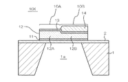
図1に示すように、本実施形態のバルク音響振動子10は、シリコン基板等の半導体などで構成される基板1と、この基板1の開口部1a上に形成される積層構造とで構成される。基板1上には酸化シリコンや窒化シリコン等の絶縁膜2が形成され、この絶縁膜2は上記開口部1a上にも形成されている。開口部1aは基板1の裏面側からエッチング処理を施すこと等により形成され、このとき、絶縁膜2は当該エッチング工程におけるエッチングストップ層として機能するようになっている。
As shown in FIG. 1, the bulk
絶縁膜2上に形成された積層構造は、それぞれ、Pt/Tiの積層構造などの金属等の導電体よりなる下部電極11と、AlN、ZnOなどの圧電体よりなる圧電体膜12と、Pt/Tiなどの金属等の導電体よりなる上部電極13とが順次に積層された構造と、非圧電体よりなる温度補償膜14とを有する。当該積層構造においては、下部電極11と上部電極13との間に交流電圧を印加することで、積層構造の内部に積層方向のバルク音響波(縦振動)が生成され、このバルク音響波の共振特性によって所定の共振周波数を備えた振動子が構成されるようになっている。
The laminated structure formed on the
上記温度補償膜14は、SiO2、TeO5、ZrOx(x=1〜2)などの誘電体からなる薄膜で構成される。ただし、当該温度補償膜をFe−Ni合金などの金属で構成することも可能である。これらの温度補償膜14は、バルク音響振動子10の温度補償、つまり周波数温度特性の低減のためのものであり、周波数温度特性を調整するために設けられている。すなわち、温度補償膜14を含まない積層構造は圧電体膜12の特性に起因して一般的に負の周波数温度特性、つまり、温度が上昇すると共振周波数が低下する特性を備えたものとなるが、温度補償膜14を形成することで、当該負の周波数温度特性の絶対値を低減することができ、また、正の周波数温度特性を備えたものとすることもできる。
The temperature compensation film 14 is composed of a thin film made of a dielectric material such as
本実施形態のバルク音響振動子10において、下部電極11と上部電極12が平面的に重なる動作平面範囲10Pには上記温度補償膜14が偏在している。すなわち、動作平面範囲10P内では、温度補償膜14が均一に形成されておらず、場所により温度補償膜14の形成の有無があり、或いは、温度補償膜14の膜厚の異なる部分が存在する。
In the bulk
具体的には、本実施形態の場合、上記温度補償膜14が形成されていない第1平面領域10Aと、上記温度補償膜14が形成された第2平面領域10Bとが設けられている。図示例の場合、第2平面領域10Bでは温度補償膜14が所定の膜厚で均一に形成されている。ここで、温度補償膜14の有無により、第1平面領域10Aだけでは負の周波数温度特性を示し、第2平面領域10Bだけでは正の周波数温度特性を示す構成となっている。そして、上記第1平面領域10Aと第2平面領域10Bとが一体に動作することにより、全体として周波数温度特性の低いバルク音響振動子10が構成されている。
Specifically, in the case of the present embodiment, a first
本実施形態では、上述のように動作平面範囲10Pのうち温度補償膜14が第2平面領域10Bに限定して形成されているので、振動子全体としての周波数温度特性を低減するためには、従来のように温度補償膜を動作平面範囲10P全体に均一に形成する場合に比べて第2平面領域10Bの温度補償膜14を厚く形成することができる。したがって、温度補償膜14の単位膜厚当たりの周波数温度特性への影響が小さくなるので、温度補償膜14の膜厚制御性が同等であっても、従来よりも温度補償の制御性を高めることが可能になる。
In the present embodiment, since the
上記の点をさらに詳細に説明すると、本実施形態では、第1平面領域10Aが負の周波数温度特性を有し、第2平面領域10Bが正の周波数温度特性を有するものとされているため、第1平面領域10Aの周波数温度特性が第2平面領域10Bの周波数温度特性によって補償され、バルク音響振動子10全体としては共振周波数の温度依存性が充分に低くなるように構成されている。例えば、両者の周波数温度特性が相互に完全に打ち消し合う関係に設定されれば、バルク音響振動子10の周波数温度係数は0になり、温度変化に対する共振周波数の高い安定性が得られる。
The above point will be described in more detail. In the present embodiment, the first
また、第1平面領域10Aと第2平面領域10Bとは常用温度域で相互に近似した共振周波数を有するように構成されている。共振周波数は、各平面領域の積層構造中の各層の弾性特性、質量、膜厚等によって定まる。例えば、音響弾性波の伝播材質中の音速が早くなるほど共振周波数は高くなり、膜厚が大きくなるほど共振周波数は低下する。この場合、バルク音響振動子10は、−40℃以上80℃以下、或いは、−20度以上60℃以下といった常用温度域内に共振周波数の大小が逆転する温度が存在するように構成されていることが好ましく、特に、その常用温度域の中心温度帯(20〜30℃の範囲内、例えば25℃)において第1平面領域10Aと第2平面領域10Bの共振周波数が同一となるように設定されることが望ましい。
In addition, the first
なお、上記実施形態では第1平面領域10Aには温度補償膜14を全く形成していないが、第1平面領域10Aにおいて、第2平面領域10Bよりも薄い温度補償膜14を形成しても構わない。ただし、この場合には第1平面領域10Aの負の周波数温度係数の絶対値が小さくなるので、その分、第2平面領域10Bの温度補償膜14Bの膜厚を減少させてその正の周波数温度係数を小さくする必要がある。
In the above embodiment, the
また、上記実施形態では、基板1に開口部1aを形成しているが、基板1の表面に凹部を形成し、この凹部上に上記積層構造を形成することで、積層構造下に空洞が設けられるように構成してもよい。このような構造は、凹部内にレジスト、SiO2膜またはPSG膜等の犠牲層を形成しておき、当該犠牲層上に上記の積層構造を形成し、その後、犠牲層をウエットエッチング等によって除去することで形成できる。また、基板1の表面上に上記積層構造内に生ずる共振周波数に対応した音響多層膜を形成し、この音響多層膜上に積層構造を形成することによってバルク音響弾性波が音響多層膜で反射されるように構成しても構わない。
Moreover, in the said embodiment, although the opening part 1a is formed in the board |
さらに、本実施形態では、従来のように積層構造全体にわたり均一に温度補償膜を形成する場合に比べて、補償精度を高めることが可能である。この点について図16及び図17を参照して以下に詳細に説明する。図16は従来の温度補償無しのバルク音響振動子について、温度25℃における共振周波数foに対する実際の共振周波数fの比率で表される周波数比f/foの温度依存性を模式的に示すグラフ、図17は本実施形態の第1平面領域10A及び第2平面領域10Bのそれぞれの構造に対応する周波数比f/foの温度依存性を模式的に示すグラフである。
Furthermore, in the present embodiment, it is possible to improve the compensation accuracy as compared with the case where the temperature compensation film is uniformly formed over the entire laminated structure as in the prior art. This point will be described in detail below with reference to FIGS. FIG. 16 is a graph schematically showing the temperature dependence of the frequency ratio f / fo represented by the ratio of the actual resonance frequency f to the resonance frequency fo at a temperature of 25 ° C. for a conventional bulk acoustic transducer without temperature compensation; FIG. 17 is a graph schematically showing the temperature dependence of the frequency ratio f / fo corresponding to the structures of the first
従来のバルク音響振動子では、図16に示すように、温度が高くなると共振周波数が単調に低下する負の周波数温度特性を示すが、これを補償するには、温度補償膜の膜厚を調整して周波数温度特性を示す図示のグラフがほぼ水平になるようにする必要がある。このようにするために必要とされる温度補償膜の膜厚は、温度補償膜の温度特性の強弱に依存するので、温度補償膜の温度特性が強ければ薄くて足り、弱ければ厚く形成する必要が生ずる。いずれの場合でも周波数温度特性を無くすために必要な要補償量は、温度補償膜の膜厚を制御することで達成されるため、温度補償膜の膜厚の制御精度によって周波数温度特性の補償精度、或いは、特性のばらつきが決定される。 As shown in FIG. 16, the conventional bulk acoustic vibrator shows a negative frequency temperature characteristic in which the resonance frequency monotonously decreases as the temperature increases. To compensate for this, the film thickness of the temperature compensation film is adjusted. Thus, it is necessary to make the illustrated graph showing the frequency temperature characteristics almost horizontal. The film thickness of the temperature compensation film required for this depends on the strength and weakness of the temperature characteristics of the temperature compensation film. Therefore, it is sufficient if the temperature characteristics of the temperature compensation film are strong. Will occur. In either case, the amount of compensation required to eliminate the frequency temperature characteristic is achieved by controlling the film thickness of the temperature compensation film. Alternatively, the characteristic variation is determined.
一方、図17に示すように、本実施形態の場合には、第1平面領域10Aが負の周波数温度特性(図示実線)を有し、第2平面領域10Bが正の周波数温度特性(図示点線)を有するので、両平面領域の周波数温度特性を図示例P,Qのように相互に打ち消し合うように設定すれば、バルク音響振動子10全体の周波数温度特性が低減され、共振周波数を安定させることができる。
On the other hand, as shown in FIG. 17, in the case of the present embodiment, the
本実施形態の場合には、第1平面領域10Aと第2平面領域10Bとで温度補償膜の有無または温度補償膜の膜厚に相違がある。従って、本実施形態の場合は、従来のように振動子全体にわたり一様に形成された温度補償膜を設ける場合よりも、第2平面領域10Bの温度補償膜の膜厚が大きくなるとともに、当該膜厚によるバルク音響振動子10全体の周波数温度特性への影響が小さくなる。その結果、温度補償膜の膜厚の制御精度が従来と同様であっても、全体の周波数温度特性をより高精度に設定することが可能になる。
In the case of this embodiment, the presence or absence of the temperature compensation film or the film thickness of the temperature compensation film differs between the first
例えば、従来の温度補償膜の膜厚の制御精度が10nmであり、この温度補償膜の膜厚差10nmに対応する周波数温度係数の変化量が5ppm/℃であるとした場合、本実施形態では、温度補償膜の膜厚の制御精度が上記と同じ10nmであっても、一方の平面領域の温度補償膜の膜厚差10nmに対応する周波数温度特性の変化量を例えば1〜2ppm/℃程度にすることができるため、周波数温度特性を従来よりも高精度に制御することができる。
For example, when the control accuracy of the film thickness of the conventional temperature compensation film is 10 nm and the change amount of the frequency temperature coefficient corresponding to the film thickness difference of 10 nm of this temperature compensation film is 5 ppm / ° C., in this embodiment, Even if the control accuracy of the film thickness of the temperature compensation film is 10 nm, the amount of change in the frequency temperature characteristic corresponding to the
また、図示例Pのように第1平面領域10Aと第2平面領域10Bの周波数差が大きくなると効率的な共振状態を得ることができなくなる虞があるが、第1平面領域10Aと第2平面領域10Bの双方にそれぞれ温度補償膜14を形成することで、図示例Qのように第1平面領域10Aの負の周波数温度特性を緩和するとともに、第2平面領域10Bの正の周波数温度特性をこれに合わせることで、より広い温度範囲において効率的な共振状態を実現できる。
Further, if the frequency difference between the first
さらに、本実施形態では、第2平面領域10Bの最上層、すなわち、上部電極13上に温度補償膜14を形成しているため、第2平面領域10Bに温度補償膜14を形成した後に、例えば、エッチングや追加の成膜処理等によって温度補償膜14の膜厚を調整することが可能になる。特に、温度補償膜14のエッチングによる膜厚削減処理は温度補償膜14を上部電極13上に形成する場合でなければ不可能である。
Furthermore, in this embodiment, since the
また、温度補償膜14は第1平面領域10Aと第2平面領域10Bの双方に形成してもよい。この場合には、第1平面領域10Aでは温度補償膜14を薄く、第2平面領域10Bでは温度補償膜を厚く形成するが、図17の図示例Qのように温度補償に要する温度補償膜14の最大膜厚を小さくすることができる。そして、両領域10A、10Bの温度補償膜14を共に上部電極13上に形成する場合には、同種の補正方法、例えば、エッチングによる膜厚削減処理のみを行う場合でも、第1平面領域10Aと第2平面領域10Bのいずれに当該処理を施すかを選択することにより、周波数温度特性を正側と負側のいずれにも調整することが可能になるというメリットがある。
Further, the
この場合、第2平面領域10Bの温度補償膜14の膜厚が第1平面領域10Aの温度補償膜14の膜厚よりも大きくなるため、下部電極11、圧電体膜12及び上部電極13の積層構造の各層の膜厚を同一に設定しても、第2平面領域10Bの共振周波数が第1平面領域10Aの共振周波数よりも低下する。したがって、第1平面領域10Aの下部電極11、圧電体膜12及び上部電極13の積層構造の膜厚合計に対して、第2平面領域10Bの下部電極11、圧電体膜12及び上部電極13の積層構造の膜厚合計を薄くするなどの方法により、第1平面領域10Aと第2平面領域10Bの常用温度域における共振周波数のずれを低減することが好ましい。
In this case, since the thickness of the
また、上記の場合には、第1平面領域10Aの温度補償膜よりも第2平面領域10Bの温度補償膜の方が厚いので、温度補償膜の膜厚差によって第2平面領域10Bの信号強度が第1平面領域10Aより低下する、すなわち、第2平面領域10Bの共振アドミタンス値が第1平面領域10Aのそれよりも低くなる。このため、図示例とは異なるが、第2平面領域10Bの面積を第1平面領域10Aの面積より大きくし、両平面領域の共振アドミタンス値(或いはその逆数であるインピーダンス値)の差を低減させることが有効な場合がある。このようにすることで、両平面領域の電気的な結合バランスが改善され、補償精度が向上し、より安定した周波数温度特性を得ることができる。図示例の場合、第1平面領域10Aと第2平面領域10Bの位置及び形状の関係を逆転させれば上記の状況とすることができる(図8参照)。
In the above case, since the temperature compensation film in the second
本実施形態のバルク音響振動子10を製造する場合には、第1平面領域10Aと第2平面領域10Bの対応する各層同士をそれぞれ並行して積層していくことが好ましい。すなわち、絶縁膜2上において、下部電極11を同一工程で形成し、圧電体膜12を同一工程で形成し、上部電極13を同一工程で形成している。さらに、両平面領域に共に温度補償膜を形成する場合には温度補償膜14を同一工程で形成することが好ましい。なお、同一工程で同時に形成される対応する各層間に膜厚の相違がある場合には、当該工程の少なくとも一部の段階を共通に行えばよい。これらの各層の成膜処理は、例えば、蒸着法、スパッタリング法、CVD法等により行うことができる。なお、以上説明した上記の各点の構成については以下の各実施形態でも同様に採用できる。
When manufacturing the bulk
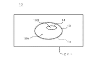
図8は、本実施形態のバルク音響振動子10の平面図である。本実施形態では、上記のように第1平面領域10Aには温度補償膜14が形成されず、第2平面領域10Bでは温度補償膜14が形成されている。ここで、図示例では動作平面範囲10P内に第1平面領域10Aと第2平面領域10Bのみが形成されている。また、第2平面領域10Bは動作平面範囲10P(すなわち第1平面領域10A)内に島状に配置されている。
FIG. 8 is a plan view of the bulk
上記の状況において、動作平面領域10Pが楕円状に構成されることによって、たとえば、動作平面領域10Pが円状に構成されていたり、相互に対向する辺同士が平行に構成された正方形、長方形、正六角形等の多角形であったり、その他の正多角形であったりする場合に比べて、横振動モードの縮退が抑制され、共振特性がスプリアスに影響されにくくなるように構成できる。また、第2平面領域10Bも楕円状に構成されることでやはり横振動モードが抑制される。
In the above situation, the
また、本実施形態では、動作平面範囲10Pの重心位置(完全な楕円であれば長軸と短軸の交点である中心位置と一致する。)に対して第2平面範囲10Bの重心がずれた位置に配置されている。一般に、任意の形状の動作平面範囲10Pの重心と、任意の形状の第2平面領域10Bの重心とがずれることで、第2平面領域10Bが動作平面範囲10P内において非対称な位置に配置されていることとなり、したがって、横振動モードの縮退が抑制されて横振動モードによる共振特性への影響が低減される。
In the present embodiment, the center of gravity of the
通常、横振動モードは平面方向の音響波が動作平面領域10P内を往復する経路上において定在波となることで発生するが、一般的には反射を繰り返すことできわめて長い往復経路を有することから、バルク音響振動子10の特性を決定する縦振動モードの周波数に比べて低い周波数しか持たない。しかし、上記横振動モードの高調波は縦振動モードの周波数に重なる虞があるため、たとえば、同様の長さの往復経路を有する横振動モードが高次に縮退したり、或いは、異なる基本周波数を持つ横振動モードの高調波の周波数域が重なると、縦振動モードの共振周波数近傍にスプリアスが現れる可能性が高くなり、バルク音響振動子の周波数特性に重大な悪影響を与える虞がある。
Normally, the transverse vibration mode is generated when a plane acoustic wave becomes a standing wave on a path that reciprocates in the
本実施形態では、第2平面領域10Bが動作平面範囲10P内の非対称位置にある(動作平面範囲10Pの重心位置とずれた位置に重心がある)ことで、実際に問題となりうる横振動モードが縮退しにくくなる。この場合、一般的には、任意の偏在分布を持つ温度補償膜14自体の重心(これは平面形状の重心とは異なり、膜厚の分布をも勘案した膜自体の重心である。)が動作平面範囲10Pの重心位置からずれていることが好ましい。
In the present embodiment, since the
また、本実施形態では第2平面領域10Bが動作平面範囲10P内で島状に構成されているので、温度補償膜14の存在状態の異なる領域間の境界が閉じた構造とされるため、横振動モードがさらに縮退しにくくなる。なお、上記実施形態の第1平面領域10Aと第2平面領域10Bの関係を反転させて、第2平面領域10B中に島状の第1平面領域10Aが形成されていてもよい。
In the present embodiment, since the second
なお、本実施形態においては、動作平面範囲10P内に第1平面領域10A及び第2平面領域10Bのみが形成されている例を示したが、これら以外の他の平面領域を有していてもよい。たとえば、動作平面範囲10P内に、温度補償膜のない領域、温度補償膜の薄い領域、温度補償膜の厚い領域の3領域を有していてもよい。もちろん、温度補償膜の膜厚分布が偏在している(均一でない)のであれば、上記とは異なり、複数の領域が明確に区分けできず、温度補償膜が徐々に厚くなったり、徐々に薄くなったりしているなどといった態様であっても構わない。
In the present embodiment, an example in which only the
[第2実施形態]
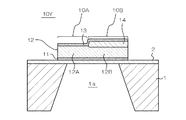
次に、図2を参照して本実施形態の第2実施形態について説明する。上記の第1実施形態のバルク音響振動子10では上部電極13の上に温度補償膜14が形成されていたが、この第2実施形態のバルク音響振動子10′では、上部電極13の下(すなわち、圧電体膜12と上部電極13の間)に温度補償膜14が形成されている。この場合でも、温度補償膜14によって周波数温度特性が正側へ変化する点では第1実施形態と同じであるが、後述するように第1実施形態の場合よりも温度補償膜14の効果が高く、より薄い膜でも高い温度補償効果が得られる。
[Second Embodiment]
Next, a second embodiment of the present embodiment will be described with reference to FIG. In the bulk
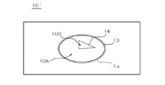
図9は本実施形態のバルク音響振動子10′の平面図である。本実施形態では、第1実施形態と同様に、第2平面領域10Bが第1平面領域10A内に島状に配置されているので、第1平面領域10Aによって動作平面範囲10Pが画成される。ただし、本実施形態の場合、第2平面領域10Bの平面形状(図示破線)は動作平面範囲10Pと相似形ではない形状となっている。このようにすると、横振動モードの縮退がさらに抑制される。また、この場合には、仮に第2平面領域10Bの重心が動作平面範囲10Pの重心位置と一致していても、横振動モードの縮退を抑制できる。
FIG. 9 is a plan view of the bulk
第2平面領域10Bの平面形状は、対向する辺同士が平行でなく、正多角形でもない多角形となっていて、図示例では三角形状に構成されている。このような平面形状は、横振動モードの縮退を抑制する上で特に効果的である。
The planar shape of the second
なお、本実施形態に関しても、第1実施形態と同様に、動作平面範囲10P内に第1平面領域10A及び第2平面領域10B以外の他の平面領域を有していてもよく、また、第1平面領域10Aと第2平面領域10Bの関係を反転させて、第2平面領域10B中に島状の第1平面領域10Aが形成されていてもよい。
As in the first embodiment, the present embodiment may have other plane areas other than the
[第3実施形態]
次に、図3乃至図7を参照して第3実施形態のバルク音響振動子10X、10Y、10Z、10V、10Wの構造について説明する。この第3実施形態では、上記第1実施形態及び第2実施形態の第1平面領域10Aと第2平面領域10Bを同様に有しているが、これらの平面領域の少なくとも一方において温度補償膜14が形成される態様の組み合わせを示すものである。なお、具体的な構造としては第1実施形態又は第2実施形態と同様の構成とすることもできるが、図示例では説明の都合上、いずれも第1平面領域10Aと第2平面領域10Bが均等に形成される態様で示してある。
[Third Embodiment]
Next, the structure of the bulk
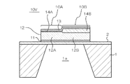
図3に示す構成例1(バルク音響振動子10X)では、第1平面領域10Aには温度補償膜を形成せず、第2平面領域10Bには上部電極13上に温度補償膜14を形成しているが、温度補償膜14の分だけ第2平面領域10Bの固有共振周波数が低下するので、これを防止するために第2平面領域10Bにある圧電体膜12の部分12Bを第1平面領域10Aにある圧電体膜12の部分12Aより薄くしている。このようにすると、両領域間の共振周波数のずれを低減できるので、振動子の一体性をより高めることができ、より効率的に縦振動を生じさせることができる。
In the configuration example 1 (bulk
図4に示す構成例2(バルク音響振動子10Y)では、上記構成例1とは異なり、温度補償膜14が上部電極13の下(圧電体膜12と上部電極13の間)に配置されている。このように温度補償膜14を一対の電極11と13の間に配置することにより、温度補償膜14の膜厚を薄くしても十分な温度補償を行うことができるため、積層構造全体を薄く形成することができる。
In the configuration example 2 (bulk
ここで、温度補償膜14を下部電極11と圧電体膜12の間に配置してもよい。ただし、この場合には、圧電体膜12の成膜状態が下地となる温度補償膜14に影響されるため、圧電体膜12の膜質が悪化する虞がある。なお、以上の各点については他の例や他の実施形態でも同様である。
Here, the
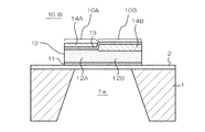
図5に示す構成例3(バルク音響振動子10Z)では、上部電極13上において第1平面領域10Aと第2平面領域10Bの双方に温度補償膜14A,14Bを設けている。この点の作用効果については第1実施形態の説明と同様である。
In Configuration Example 3 (bulk acoustic transducer 10Z) shown in FIG. 5,
図6に示す構成例4(バルク音響振動子10V)では、図5に示す構成例3と同様に第1平面領域10Aと第2平面領域10Bの双方に温度補償膜14A,14Bを設けているが、これらの温度補償膜14A,14Bをいずれも上部電極13の下、具体的には圧電体膜12と上部電極13の間に配置している。このようにすると、温度補償膜14A,14Bの膜厚を薄くすることができる。
In Configuration Example 4 (bulk
図7に示す構成例5(バルク音響振動子10W)では、第1平面領域10Aの温度補償膜14Aを上部電極13上に形成するとともに、第2平面領域10Bの温度補償膜14Bを上部電極13下に配置している。このようにすると、後に説明するように、周波数温度特性を低減しつつ、第1平面領域10Aの温度補償膜14Aの膜厚と、第2平面領域10Bの温度補償膜14Bの膜厚の差を低減できる。この膜厚の差の低減は、共振周波数の整合性を確保するために好適であり、共振周波数を合わせるために、例えば第1平面領域10Aの圧電体膜の部分12Aと、第2平面領域10Bの圧電体膜の部分12Bとの膜厚の差を大きくしなくても共振周波数を整合させることができる。
In the configuration example 5 (bulk acoustic vibrator 10W) shown in FIG. 7, the
ここで、構成例5では、温度補償膜14Aと14Bが相互に異なる膜厚を有するだけでなく、相互に異なる積層位置に構成されている。このように温度補償膜の積層位置が相互に異なる場合も、温度補償膜が偏在している態様に含まれる。
Here, in the configuration example 5, the
なお、上記とは逆に、第1平面領域10Aの温度補償膜14Aを上部電極13の下に配置し、第2平面領域10Bの温度補償膜14Bを上部電極13の上に配置してもよい。このようにすると、温度補償膜の部分14Bの膜厚を大きくすることができるため、温度補償膜の部分14Bの膜厚を調整することで、周波数温度特性を高精度に補償できる。
Contrary to the above, the
また、上記の各実施形態や例においては、各平面領域において、温度補償膜を上部電極上と上部電極下の双方に形成してもよい。このようにすると、温度補償膜を上部電極上にのみ形成した場合に比べて全体の膜厚を低減できるとともに、最上層に温度補償膜を配置できるために当該温度補償膜に対して膜厚の後調整を行うことが可能になる。 In each of the above embodiments and examples, the temperature compensation film may be formed on both the upper electrode and the lower electrode in each planar region. In this way, the overall film thickness can be reduced as compared with the case where the temperature compensation film is formed only on the upper electrode, and the temperature compensation film can be disposed on the uppermost layer, so that the film thickness of the temperature compensation film is less than that of the temperature compensation film. Post adjustments can be made.
[実施例の特性]
次に、図10乃至図15を参照して、上記各実施形態に関連するバルク音響振動子の積層構造の特性について説明する。以下に示す特性は、基板1として厚みが200〜300μm程度のシリコン単結晶基板を用い、下部電極として膜厚30nmのTi層の上に膜厚150nmのPt層を形成したものを用い、圧電体膜として膜厚700nmのAlN層を形成したものを用い、さらに、上部電極として膜厚30nmのTi層の上に膜厚150nmのPt層を形成したものを用い、温度補償膜としてSiO2(酸化シリコン)層を形成してなる例に対するものである。
[Characteristics of Example]
Next, with reference to FIG. 10 to FIG. 15, characteristics of the laminated structure of the bulk acoustic vibrator related to each of the above embodiments will be described. The following characteristics are obtained by using a silicon single crystal substrate having a thickness of about 200 to 300 μm as the
図10は、従来のように均一な積層構造を有するバルク音響振動子の周波数温度係数Δf/fo[ppm/℃](Δfは1℃当たりの共振周波数の変化量)の温度補償膜の膜厚依存性を示すグラフである。ここで、図示破線は温度補償膜を上部電極下に形成した場合の特性、図示一点鎖線は温度補償膜を上部電極上に形成した場合の特性を示す。図10に示すように、温度補償膜がない場合には周波数温度係数が−40[ppm/℃]程度であるが、温度補償膜の膜厚を増大させるに従って周波数温度係数が単調に増加しているのがわかる。 FIG. 10 shows the film thickness of the temperature compensation film having a frequency temperature coefficient Δf / fo [ppm / ° C.] (Δf is the amount of change in resonance frequency per 1 ° C.) of a bulk acoustic vibrator having a uniform laminated structure as in the prior art. It is a graph which shows dependence. Here, the broken line in the figure shows the characteristic when the temperature compensation film is formed under the upper electrode, and the alternate long and short dash line in the figure shows the characteristic when the temperature compensation film is formed on the upper electrode. As shown in FIG. 10, the frequency temperature coefficient is about −40 ppm / ° C. when there is no temperature compensation film, but the frequency temperature coefficient increases monotonously as the film thickness of the temperature compensation film is increased. I can see that
また、温度補償膜を上部電極下に形成した場合には、温度補償膜の膜厚がx(40〜50nm程度)で周波数温度係数がほぼ0となり、温度補償膜の膜厚に対する周波数温度係数の依存性がきわめて大きいが、温度補償膜を上部電極上に形成した場合には、温度補償膜の膜厚がy(540〜600nm程度)で周波数温度係数がほぼ0となり、温度補償膜の膜厚に対する周波数温度係数の依存性が緩やかであることがわかる。 When the temperature compensation film is formed under the upper electrode, the frequency temperature coefficient is almost 0 when the film thickness of the temperature compensation film is x (about 40 to 50 nm), and the frequency temperature coefficient with respect to the film thickness of the temperature compensation film is Although the dependence is very large, when the temperature compensation film is formed on the upper electrode, the temperature temperature film becomes y (about 540 to 600 nm) and the frequency temperature coefficient becomes almost zero, and the film thickness of the temperature compensation film. It can be seen that the dependence of the frequency temperature coefficient on is moderate.
したがって、上記の特性により、従来の均質構造で周波数温度特性を補償しようとすれば、例えば温度補償膜を上部電極下に形成する場合には温度補償膜の膜厚を図示x(40〜50nm程度)、温度補償膜を上部電極上に形成する場合には温度補償膜の膜厚を図示y(540〜600nm程度)とすればよい。ここで、温度補償膜を上部電極下に形成する場合には、温度補償膜の膜厚が薄くても足りるため製造効率は高いが、温度補償膜の膜厚に対する周波数温度係数の依存性が強いため、10nm程度の成膜精度でも周波数温度特性に或る程度のばらつきが生ずる。これに対して、温度補償膜を上部電極上に形成する場合には、温度補償膜の膜厚に対する周波数温度係数の依存性が弱いため、周波数温度特性を低減し、共振周波数を安定させることは比較的容易であるが、温度補償膜を厚く形成する必要があることから製造効率が悪化する。また、温度補償膜が厚くなることにより共振周波数が低下する一方、共振周波数の低下を回避するために圧電体膜を薄く形成すると振動子強度の低下や膜質の悪化による電気機械結合係数の低下などが生じるなど、高周波化が難しくなるという問題点がある。 Therefore, if it is attempted to compensate the frequency temperature characteristic with the conventional homogeneous structure by the above characteristics, for example, when the temperature compensation film is formed under the upper electrode, the film thickness of the temperature compensation film is illustrated as x (about 40 to 50 nm). ) When the temperature compensation film is formed on the upper electrode, the thickness of the temperature compensation film may be y (about 540 to 600 nm). Here, when the temperature compensation film is formed under the upper electrode, it is sufficient that the temperature compensation film is thin, so that the manufacturing efficiency is high, but the dependence of the temperature coefficient on the temperature compensation film thickness is strong. For this reason, even if the film forming accuracy is about 10 nm, some variation occurs in the frequency temperature characteristics. On the other hand, when the temperature compensation film is formed on the upper electrode, since the dependence of the frequency temperature coefficient on the film thickness of the temperature compensation film is weak, it is possible to reduce the frequency temperature characteristic and stabilize the resonance frequency. Although it is relatively easy, manufacturing efficiency deteriorates because the temperature compensation film needs to be formed thick. In addition, the resonance frequency decreases as the temperature compensation film becomes thicker. On the other hand, if the piezoelectric film is formed thin in order to avoid a decrease in the resonance frequency, the strength of the vibrator or the electromechanical coupling coefficient decreases due to deterioration of the film quality. There is a problem that high frequency becomes difficult.
一方、本実施形態では、温度補償膜14が動作平面範囲10P内で偏在して設けられていることにより、負の周波数温度特性を備えた領域と正の周波数温度特性を備えた領域とで互いに周波数温度特性を補償し合うようにすることで、バルク音響振動子全体の周波数温度特性を低減できる。したがって、温度補償膜14の偏在分布によって種々の方法でバルク音響振動子全体の周波数温度特性を低減することができる。具体的には、第1平面領域10Aに温度補償膜を形成せず、第2平面領域10Bに温度補償膜を形成する場合には、バルク音響振動子全体に温度補償膜を形成する従来構造に比べて、温度補償に必要な第2平面領域10Bにおける温度補償膜の膜厚が相対的に増大するので、当該温度補償膜の膜厚の制御精度が同程度であっても、従来構造よりも高精度に周波数温度特性を設定することが可能になる。
On the other hand, in the present embodiment, since the
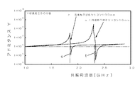
また、第1平面領域10Aと第2平面領域10Bの双方に温度補償膜を形成する場合でも、第2平面領域10Bに正の周波数温度特性を設ける必要があることには変わりがないために第2平面領域10Bの温度補償膜の膜厚は従来よりも大きくなるから、上記の点は同様に妥当する。また、この場合には、第1平面領域10Aの周波数温度特性も緩和されるとともに、この緩和された第1平面領域10Aの周波数温度特性に合わせて第2平面領域10Bの周波数温度特性を設定すればよいので、周波数温度特性の後調整が容易になるという利点がある。例えば、図11に示すように、上部電極下に膜厚10nmの温度補償膜を形成すると負の周波数温度特性が得られ、上記電極下に膜厚100nmの温度補償膜を形成すると正の周波数温度特性が得られるが、いずれの周波数温度特性も、温度補償膜のないバルク音響振動子の周波数温度特性よりも緩和された特性を有している。
Further, even when the temperature compensation film is formed in both the first
さらに、本実施形態では、温度補償膜の形成態様に関する選択肢が増大し、様々な組合せで好適な振動子特性を狙うことが可能になる。すなわち、第1平面領域10Aに温度補償膜を形成しない場合には、図10に示すように、第2平面領域10Bの温度補償膜の膜厚を図示e(180〜190nm程度)とするか、或いは、図示f(780〜800nm程度)とすればよく、また、第1平面領域10Aと第2平面領域10Bの双方に共に温度補償膜を形成する場合には、第1平面領域10Aの温度補償膜の膜厚を図示a(10〜20nm程度)とし、第2平面領域10Bの温度補償膜の膜厚を図示b(100〜110nm程度)とすること、或いは、第1平面領域10Aの膜厚を図示c(390〜410nm程度)とし、第2平面領域10Bの膜厚を図示d(670〜690nm程度)とすることで、周波数温度特性を低減できるほか、第1平面領域10Aの温度補償膜の膜厚を図示cとし、第2平面領域10Bの温度補償膜の膜厚を図示bとすることによっても周波数温度特性を低減できる。
Furthermore, in this embodiment, the choice regarding the formation aspect of a temperature compensation film increases, and it becomes possible to aim at suitable vibrator characteristics in various combinations. That is, when the temperature compensation film is not formed in the first
また、上記の第3実施形態の各構成例で示したようにバルク音響振動子における温度補償膜の位置及び膜厚の複数の組合せが可能であることにより、共振周波数を広い範囲に設定できるなど、素子設計の自由度が増大するという利点がある。 In addition, as shown in each configuration example of the third embodiment, the resonance frequency can be set in a wide range by allowing a plurality of combinations of positions and film thicknesses of the temperature compensation film in the bulk acoustic vibrator. There is an advantage that the degree of freedom in element design increases.
図12は、図11に示す2つの周波数温度特性を備えたバルク音響振動子におけるアドミタンス特性を示すグラフである。上部電極下に膜厚100nmの温度補償膜を形成した場合には共振周波数s(1.85GHz程度)であり、上部電極下に膜厚10nmの温度補償膜を形成した場合の共振周波数t(2.3GHz程度)より低くなる。これは、温度補償膜が厚くなることにより振動子の質量が増大したためと考えられる。 FIG. 12 is a graph showing admittance characteristics in the bulk acoustic vibrator having the two frequency temperature characteristics shown in FIG. When a temperature compensation film with a film thickness of 100 nm is formed under the upper electrode, the resonance frequency is s (about 1.85 GHz), and when the temperature compensation film with a film thickness of 10 nm is formed under the upper electrode, the resonance frequency t (2 .About 3 GHz). This is presumably because the mass of the vibrator is increased by increasing the temperature compensation film.
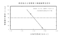
図13には、上部電極下の温度補償膜の膜厚と共振周波数との関係を示す。上記のように、温度補償膜を厚くすると共振周波数は単調に低下していく。したがって、第1平面領域と第2平面領域の共振周波数をなるべく一致させるためには、温度補償膜以外の積層構造を両平面領域において異なる厚みに形成しておく必要がある。 FIG. 13 shows the relationship between the thickness of the temperature compensation film below the upper electrode and the resonance frequency. As described above, when the temperature compensation film is thickened, the resonance frequency decreases monotonously. Therefore, in order to match the resonance frequencies of the first planar region and the second planar region as much as possible, it is necessary to form laminated structures other than the temperature compensation film with different thicknesses in both planar regions.
図14には、上部電極下の温度補償膜の膜厚が一定(100nm)のときの圧電体膜の膜厚と共振周波数との関係を示す。このように、圧電体膜の膜厚が小さくなると共振周波数は単調に増大する。例えば、上部電極下の温度補償膜の膜厚が100nmのときに圧電体膜の膜厚を500nmまで薄くすると、共振周波数は上部電極下の温度補償膜の膜厚が10nmで圧電体膜の膜厚が700nmのときの共振周波数とほぼ一致する。したがって、第1平面領域10Aの圧電体膜の膜厚を厚く(例えば700nm)し、第2平面領域10Bの圧電体膜の膜厚を薄く(例えば500nm)しておくことで、異なる厚みの温度補償膜を形成しても両平面領域間の共振周波数のずれを低減することができる。
FIG. 14 shows the relationship between the film thickness of the piezoelectric film and the resonance frequency when the film thickness of the temperature compensation film under the upper electrode is constant (100 nm). Thus, the resonance frequency monotonously increases as the thickness of the piezoelectric film decreases. For example, if the film thickness of the piezoelectric film is reduced to 500 nm when the film thickness of the temperature compensation film under the upper electrode is 100 nm, the resonance frequency is 10 nm when the film thickness of the temperature compensation film under the upper electrode is 10 nm. It almost coincides with the resonance frequency when the thickness is 700 nm. Therefore, by increasing the film thickness of the piezoelectric film in the first
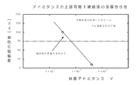
また、図10に示すように、上部電極下に膜厚100nmの温度補償膜を形成した場合の共振アドミタンスは上部電極下に膜厚10nmの温度補償膜を形成した場合の共振アドミタンスよりも小さい。これは、非圧電体(誘電体)よりなる温度補償膜が厚くなることにより振動子のインピーダンスが増大したためと考えられる。このように第2平面領域10Bの温度補償膜の膜厚を第1平面領域10Aよりも大きくした場合、第1平面領域10Aと第2平面領域10Bの特性を整合させるために、第2平面領域10Bの共振アドミタンスを増加させる必要がある。これには、例えば、第1平面領域10Aに対して、第2平面領域10Bの面積を増大させることが考えられる。
Further, as shown in FIG. 10, the resonance admittance when the temperature compensation film having a film thickness of 100 nm is formed below the upper electrode is smaller than the resonance admittance when the temperature compensation film having the film thickness of 10 nm is formed below the upper electrode. This is presumably because the impedance of the vibrator is increased by increasing the temperature compensation film made of a non-piezoelectric material (dielectric material). Thus, when the film thickness of the temperature compensation film in the second
図15には、圧電体膜の膜厚が700nmのときの上部電極下の温度補償膜の膜厚と共振アドミタンスとの関係を示す。これによれば、温度補償膜の膜厚が小さくなると共振アドミタンスは増大することがわかる。例えば、上部電極下の温度補償膜の膜厚が100nmの場合に比べて、上部電極下の温度補償膜の膜厚が10nmの場合の共振アドミタンスは10倍程度になるため、前者の温度補償膜の膜厚を備えた第2平面領域10Aの面積を後者の温度補償膜の膜厚を備えた第1平面領域の面積の10倍とすれば、両平面領域の共振アドミタンスがほぼ均衡することとなる。すなわち、両平面領域の面積比を単位面積当たりの共振アドミタンス比の逆数とすることで、共振アドミタンスの均衡を図ることができる。
FIG. 15 shows the relationship between the thickness of the temperature compensation film below the upper electrode and the resonant admittance when the thickness of the piezoelectric film is 700 nm. This shows that the resonance admittance increases as the thickness of the temperature compensation film decreases. For example, since the resonant admittance when the film thickness of the temperature compensation film under the upper electrode is 10 nm is about 10 times that when the film thickness of the temperature compensation film under the upper electrode is 100 nm, the former temperature compensation film If the area of the second
本実施形態では、上述のように温度補償膜の偏在によって横振動モードの縮退を抑制し、振動子特性上重要な周波数域で不要なスプリアスを生じないようにすることができるという効果を有する。たとえば、図12に示すアドミタンス特性において、横振動モードが縮退すると、その高調波によって共振周波数s又はtの近傍にスプリアスが発生し、これがフィルタ特性等を悪化させる。しかし、本実施形態では横振動モードの縮退が抑制されるため、上記のスプリアスによる特性悪化を防止できる。 In the present embodiment, as described above, there is an effect that it is possible to suppress the degeneration of the transverse vibration mode by the uneven distribution of the temperature compensation film, and to prevent unnecessary spurious signals from being generated in a frequency range important for vibrator characteristics. For example, in the admittance characteristics shown in FIG. 12, when the transverse vibration mode is degenerated, spurious is generated in the vicinity of the resonance frequency s or t due to the harmonics, which deteriorates the filter characteristics and the like. However, in this embodiment, since the degeneration of the transverse vibration mode is suppressed, the deterioration of characteristics due to the above spurious can be prevented.
尚、本発明のバルク音響振動子は、上述の図示例にのみ限定されるものではなく、本発明の要旨を逸脱しない範囲内において種々変更を加え得ることは勿論である。たとえば、上記実施形態の構成及びその説明では、バルク音響振動子の周波数温度特性を十分に低減した例を挙げたが、本発明では横振動モードの縮退の抑制と、周波数温度特性の制御性の向上とを図ることができるものであればよく、周波数温度特性を0に十分に近づけたものでなくても構わない。 It should be noted that the bulk acoustic transducer of the present invention is not limited to the illustrated example described above, and it is needless to say that various modifications can be made without departing from the gist of the present invention. For example, in the configuration of the above embodiment and the description thereof, an example in which the frequency temperature characteristic of the bulk acoustic vibrator is sufficiently reduced has been described. However, in the present invention, the suppression of the lateral vibration mode degeneration and the controllability of the frequency temperature characteristic are described. Any device that can improve the frequency temperature characteristics may be used, and the frequency temperature characteristics need not be sufficiently close to zero.
1…基板、1a…開口部、2…絶縁膜、10、10′、10X、10Y、10Z、10V、10W…バルク音響振動子、10P…動作平面範囲、10A…第1平面領域、10B…第2平面領域、11…下部電極、12…圧電体膜、12A,12B…圧電体膜の部分、13…上部電極、14、14A,14B…温度補償膜
DESCRIPTION OF
Claims (9)
前記積層構造のうち少なくとも前記一対の電極同士が前記圧電体膜を介して平面的に重なる動作平面範囲内で前記温度補償膜が偏在していることを特徴とするバルク音響振動子。 In a bulk acoustic vibrator having a piezoelectric film, a laminated structure including a pair of electrodes sandwiching the piezoelectric film, and a temperature compensation film,
The bulk acoustic vibrator is characterized in that the temperature compensation film is unevenly distributed within an operation plane range in which at least the pair of electrodes in the laminated structure overlaps with each other through the piezoelectric film.
Priority Applications (1)
| Application Number | Priority Date | Filing Date | Title |
|---|---|---|---|
| JP2007051232A JP2008219237A (en) | 2007-03-01 | 2007-03-01 | Bulk acoustic resonator |
Applications Claiming Priority (1)
| Application Number | Priority Date | Filing Date | Title |
|---|---|---|---|
| JP2007051232A JP2008219237A (en) | 2007-03-01 | 2007-03-01 | Bulk acoustic resonator |
Publications (2)
| Publication Number | Publication Date |
|---|---|
| JP2008219237A true JP2008219237A (en) | 2008-09-18 |
| JP2008219237A5 JP2008219237A5 (en) | 2010-04-08 |
Family
ID=39838788
Family Applications (1)
| Application Number | Title | Priority Date | Filing Date |
|---|---|---|---|
| JP2007051232A Withdrawn JP2008219237A (en) | 2007-03-01 | 2007-03-01 | Bulk acoustic resonator |
Country Status (1)
| Country | Link |
|---|---|
| JP (1) | JP2008219237A (en) |
Cited By (9)
| Publication number | Priority date | Publication date | Assignee | Title |
|---|---|---|---|---|
| CN101895269A (en) * | 2010-07-30 | 2010-11-24 | 中国科学院声学研究所 | Method for preparing piezoelectric film bulk acoustic wave resonator |
| CN102577118A (en) * | 2009-09-28 | 2012-07-11 | Vtt技术研究中心 | A micromechanical resonator |
| JP2012156907A (en) * | 2011-01-27 | 2012-08-16 | Murata Mfg Co Ltd | Piezoelectric device |
| US20140191825A1 (en) * | 2013-01-09 | 2014-07-10 | Samsung Electronics Co., Ltd. | Radio frequency filter and manufacturing method thereof |
| US20150130559A1 (en) * | 2013-11-11 | 2015-05-14 | Taiyo Yuden Co., Ltd. | Piezoelectric thin film resonator, filter and duplexer |
| US9344059B2 (en) | 2013-01-28 | 2016-05-17 | Taiyo Yuden Co., Ltd. | Piezoelectric thin film resonator, filter, and duplexer including a film inserted into the piezoelectric film |
| US20160164489A1 (en) * | 2014-12-08 | 2016-06-09 | Samsung Electro-Mechanics Co., Ltd. | Bulk acoustic wave resonator and filter |
| US9787282B2 (en) | 2013-11-11 | 2017-10-10 | Taiyo Yuden Co., Ltd. | Piezoelectric thin film resonator, filter and duplexer |
| WO2024044874A1 (en) * | 2022-08-29 | 2024-03-07 | 北京京东方技术开发有限公司 | Bulk acoustic resonator and manufacturing method therefor, and electronic device |
Citations (5)
| Publication number | Priority date | Publication date | Assignee | Title |
|---|---|---|---|---|
| JP2000332570A (en) * | 1999-05-24 | 2000-11-30 | Kyocera Corp | Piezoelectric resonator |
| JP2002237738A (en) * | 2000-12-06 | 2002-08-23 | Murata Mfg Co Ltd | Piezoelectric resonator, piezoelectric filter and duplexer |
| JP2005159402A (en) * | 2003-11-20 | 2005-06-16 | Matsushita Electric Ind Co Ltd | Acoustic resonator |
| JP2005223808A (en) * | 2004-02-09 | 2005-08-18 | Murata Mfg Co Ltd | Piezoelectric thin film filter, branching filter, and communication apparatus |
| JP2007028594A (en) * | 2005-06-17 | 2007-02-01 | Matsushita Electric Ind Co Ltd | Multi-mode thin film acoustic wave resonator filter, ladder-type filter with same, duplexer, and communication apparatus |
-
2007
- 2007-03-01 JP JP2007051232A patent/JP2008219237A/en not_active Withdrawn
Patent Citations (5)
| Publication number | Priority date | Publication date | Assignee | Title |
|---|---|---|---|---|
| JP2000332570A (en) * | 1999-05-24 | 2000-11-30 | Kyocera Corp | Piezoelectric resonator |
| JP2002237738A (en) * | 2000-12-06 | 2002-08-23 | Murata Mfg Co Ltd | Piezoelectric resonator, piezoelectric filter and duplexer |
| JP2005159402A (en) * | 2003-11-20 | 2005-06-16 | Matsushita Electric Ind Co Ltd | Acoustic resonator |
| JP2005223808A (en) * | 2004-02-09 | 2005-08-18 | Murata Mfg Co Ltd | Piezoelectric thin film filter, branching filter, and communication apparatus |
| JP2007028594A (en) * | 2005-06-17 | 2007-02-01 | Matsushita Electric Ind Co Ltd | Multi-mode thin film acoustic wave resonator filter, ladder-type filter with same, duplexer, and communication apparatus |
Cited By (15)
| Publication number | Priority date | Publication date | Assignee | Title |
|---|---|---|---|---|
| CN102577118A (en) * | 2009-09-28 | 2012-07-11 | Vtt技术研究中心 | A micromechanical resonator |
| JP2013506334A (en) * | 2009-09-28 | 2013-02-21 | テクノロギアン トゥトキムスケスクス ヴェーテーテー | Micromechanical resonator |
| CN102577118B (en) * | 2009-09-28 | 2016-03-16 | 芬兰国家技术研究中心股份公司 | Micromechanical resonator |
| CN101895269B (en) * | 2010-07-30 | 2012-09-05 | 中国科学院声学研究所 | Method for preparing piezoelectric film bulk acoustic wave resonator |
| CN101895269A (en) * | 2010-07-30 | 2010-11-24 | 中国科学院声学研究所 | Method for preparing piezoelectric film bulk acoustic wave resonator |
| JP2012156907A (en) * | 2011-01-27 | 2012-08-16 | Murata Mfg Co Ltd | Piezoelectric device |
| US9954511B2 (en) * | 2013-01-09 | 2018-04-24 | Samsung Electronics Co., Ltd. | Radio frequency filter and manufacturing method thereof |
| US20140191825A1 (en) * | 2013-01-09 | 2014-07-10 | Samsung Electronics Co., Ltd. | Radio frequency filter and manufacturing method thereof |
| US9344059B2 (en) | 2013-01-28 | 2016-05-17 | Taiyo Yuden Co., Ltd. | Piezoelectric thin film resonator, filter, and duplexer including a film inserted into the piezoelectric film |
| US20150130559A1 (en) * | 2013-11-11 | 2015-05-14 | Taiyo Yuden Co., Ltd. | Piezoelectric thin film resonator, filter and duplexer |
| US9787282B2 (en) | 2013-11-11 | 2017-10-10 | Taiyo Yuden Co., Ltd. | Piezoelectric thin film resonator, filter and duplexer |
| US9356573B2 (en) * | 2013-11-11 | 2016-05-31 | Taiyo Yuden Co., Ltd. | Piezoelectric thin film resonator, filter and duplexer including a film inserted in the piezoelectric film |
| US20160164489A1 (en) * | 2014-12-08 | 2016-06-09 | Samsung Electro-Mechanics Co., Ltd. | Bulk acoustic wave resonator and filter |
| US10110197B2 (en) * | 2014-12-08 | 2018-10-23 | Samsung Electro-Mechanics Co., Ltd. | Bulk acoustic wave resonator and filter |
| WO2024044874A1 (en) * | 2022-08-29 | 2024-03-07 | 北京京东方技术开发有限公司 | Bulk acoustic resonator and manufacturing method therefor, and electronic device |
Similar Documents
| Publication | Publication Date | Title |
|---|---|---|
| JP2008219237A (en) | Bulk acoustic resonator | |
| US9461616B2 (en) | Bulk wave resonator having an aluminum nitride film containing scandium and ScAlN protective layer | |
| US9991867B2 (en) | Piezoelectric acoustic resonator with adjustable temperature compensation capability | |
| JP4252584B2 (en) | Piezoelectric thin film resonator and filter | |
| US8830012B2 (en) | Composite bulk acoustic wave resonator | |
| CN103607178B (en) | Thin film wave resonator and the method improving its quality factor | |
| KR102642910B1 (en) | Acoustic resonator and method of manufacturing thereof | |
| JP5161698B2 (en) | Piezoelectric thin film resonator and filter or duplexer using the same | |
| JP4428354B2 (en) | Piezoelectric thin film resonator | |
| KR101901696B1 (en) | Bulk acoustic wave resonator and filter including the same | |
| WO2021021730A3 (en) | Doped bulk acoustic wave (baw) resonator structures, devices and systems | |
| JPWO2007088696A1 (en) | Piezoelectric vibration device | |
| TW201828512A (en) | Piezoelectric vibrating piece and piezoelectric device | |
| US10771032B2 (en) | Method for manufacturing piezoelectric thin-film element | |
| US10862448B2 (en) | Piezoelectric thin film resonator, filter, and multiplexer | |
| US10205432B2 (en) | Piezoelectric thin film resonator, filter, and duplexer | |
| CN111010108A (en) | Bulk acoustic wave resonator with recess and air wing structure, filter and electronic device | |
| US9166557B2 (en) | Piezoelectric thin film resonator and filter | |
| CN114006595B (en) | Bulk acoustic wave resonator and bulk acoustic wave filter | |
| JP2017139707A (en) | Piezoelectric thin film resonator, filter, and duplexer | |
| JP2009100196A (en) | Piezoelectric vibrating apparatus | |
| JP4978210B2 (en) | Manufacturing method of bulk acoustic vibrator | |
| JP2005311849A (en) | Piezoelectric membrane resonator, filter and method for manufacturing piezoelectric membrane resonator | |
| JP4339604B2 (en) | Piezoelectric thin film element | |
| JP2008182511A (en) | Bulk acoustic vibrator, compensating method for frequency temperature characteristic thereof, and manufacturing method thereof |
Legal Events
| Date | Code | Title | Description |
|---|---|---|---|
| A521 | Written amendment |
Effective date: 20100219 Free format text: JAPANESE INTERMEDIATE CODE: A523 |
|
| A621 | Written request for application examination |
Free format text: JAPANESE INTERMEDIATE CODE: A621 Effective date: 20100219 |
|
| A977 | Report on retrieval |
Free format text: JAPANESE INTERMEDIATE CODE: A971007 Effective date: 20120604 |
|
| A131 | Notification of reasons for refusal |
Effective date: 20120612 Free format text: JAPANESE INTERMEDIATE CODE: A131 |
|
| A761 | Written withdrawal of application |
Free format text: JAPANESE INTERMEDIATE CODE: A761 Effective date: 20120808 |