JP2008206807A - Merchandise display stand - Google Patents
Merchandise display stand Download PDFInfo
- Publication number
- JP2008206807A JP2008206807A JP2007047482A JP2007047482A JP2008206807A JP 2008206807 A JP2008206807 A JP 2008206807A JP 2007047482 A JP2007047482 A JP 2007047482A JP 2007047482 A JP2007047482 A JP 2007047482A JP 2008206807 A JP2008206807 A JP 2008206807A
- Authority
- JP
- Japan
- Prior art keywords
- display stand
- display
- side end
- main body
- product
- Prior art date
- Legal status (The legal status is an assumption and is not a legal conclusion. Google has not performed a legal analysis and makes no representation as to the accuracy of the status listed.)
- Withdrawn
Links
- 230000002265 prevention Effects 0.000 claims abstract description 19
- 230000015572 biosynthetic process Effects 0.000 abstract 1
- 238000005452 bending Methods 0.000 description 4
- NJPPVKZQTLUDBO-UHFFFAOYSA-N novaluron Chemical compound C1=C(Cl)C(OC(F)(F)C(OC(F)(F)F)F)=CC=C1NC(=O)NC(=O)C1=C(F)C=CC=C1F NJPPVKZQTLUDBO-UHFFFAOYSA-N 0.000 description 3
- XEEYBQQBJWHFJM-UHFFFAOYSA-N Iron Chemical compound [Fe] XEEYBQQBJWHFJM-UHFFFAOYSA-N 0.000 description 2
- 230000001154 acute effect Effects 0.000 description 2
- 230000037431 insertion Effects 0.000 description 2
- 238000003780 insertion Methods 0.000 description 2
- 239000002184 metal Substances 0.000 description 2
- 229910052751 metal Inorganic materials 0.000 description 2
- 230000000694 effects Effects 0.000 description 1
- 229910052742 iron Inorganic materials 0.000 description 1
- 239000000463 material Substances 0.000 description 1
- 230000002787 reinforcement Effects 0.000 description 1
- 230000003014 reinforcing effect Effects 0.000 description 1
Images



Landscapes
- Display Racks (AREA)
Abstract
Description
本発明は、商店、スーパーマーケット、百貨店等において使用される商品陳列台に関する。 The present invention relates to a commodity display stand used in a store, a supermarket, a department store, or the like.
商品陳列台は、売り場の広さや陳列する商品の種類によって、各種の形態のものが使用されている。たとえば、水平な陳列面を有する商品陳列台を、単独に使用するか、または複数個を一列に連続配置して使用するか、さらには、これら単独または複数個を配置した左右側端に、専用の側端陳列台を配置して使用されている(特許文献1)。 Various types of merchandise display stands are used depending on the size of the sales floor and the type of merchandise to be displayed. For example, a product display stand having a horizontal display surface can be used alone, or a plurality of product display stands can be used continuously in a row. The side end display stand is arranged and used (Patent Document 1).
しかし、専用の側端陳列台は、それを使用しない場合には、バックヤード等に移動させなければならず、そのための手数を要するとともに、バックヤード等が狭い場合には、対応が容易でないという問題があった。
本発明は、従来の前記問題点に鑑み、陳列台本体の側方に、必要に応じて、容易に陳列面を形成することができるとともに、前記側方の陳列面を使用しない場合にも、バックヤード等に移動させる手数を要しない商品陳列台を提供することを目的とする。 In view of the conventional problems, the present invention can easily form a display surface on the side of the display base body, if necessary, and also when not using the side display surface, An object of the present invention is to provide a commodity display stand that does not require the effort to move to a backyard or the like.
上記課題は、「特許請求の範囲」の欄における各請求項に記載するように、次のような構成からなる発明によって解決される。
(1)前後両側に陳列面を設け、左右側端に上端部が前記陳列面より上方に突出する落下防止壁を設けた陳列台本体における陳列面下方の内部空間内に、側端陳列台を格納可能にするとともに、陳列台本体における左右少なくとも一方の落下防止壁の下部に上向凹入孔を設け、かつ前記側端陳列台を前記上向凹入孔から引き出して、陳列台本体の側方に配置して使用しうるようにした商品陳列台とする。
The above-described problems are solved by the invention having the following configuration, as described in each claim in the section “Claims”.
(1) A side end display stand is provided in an internal space below the display surface of the display stand main body provided with display surfaces on both front and rear sides, and provided with a fall prevention wall with upper end portions projecting upward from the display surface at left and right side ends. The storage base is provided with an upward recessed hole in the lower part of at least one of the left and right fall prevention walls of the display base body, and the side end display base is pulled out from the upward recessed hole, A product display stand that can be used by placing it on the side.
(2)上記(1)項において、陳列台本体における前後両側の陳列面を、切妻屋根式の形状とする。 (2) In the above section (1), the display surfaces on both the front and rear sides of the display stand main body have a gable roof type shape.
(3)上記(1)項または(2)項において、側端陳列台を、陳列台本体における陳列面下方の内部空間内に格納した際に、側端陳列台の外側面により、陳列台本体の落下防止壁の上向凹入孔を閉塞し、かつ側端陳列台の前記外側面と、陳列台本体の落下防止壁とが、実質的に同一平面上に位置しうるようにする。 (3) In the above paragraph (1) or (2), when the side end display stand is stored in the internal space below the display surface of the display stand main body, the display stand main body is formed by the outer surface of the side end display stand. And the outer side surface of the side end display stand and the fall prevention wall of the display stand main body can be positioned substantially on the same plane.
(4)上記(1)項〜(3)項のいずれかにおいて、側端陳列台を、陳列台本体に引き出し可能に取り付ける。 (4) In any one of the above items (1) to (3), the side end display stand is attached to the display stand main body so that it can be pulled out.
(5)上記(4)項において、側端陳列台の陳列台本体側を支持する脚として、陳列台本体の支持脚をもって兼用させる。 (5) In the above item (4), the supporting leg of the display stand main body is also used as a leg for supporting the display stand main body side of the side end display stand.
(6)上記(1)項〜(5)項のいずれかにおいて、側端陳列台を箱状に形成し、その内部空間を収容空間とする。 (6) In any one of the above items (1) to (5), the side end display stand is formed in a box shape, and its internal space is used as a storage space.
本発明によると、次のような効果が奏せられる。
請求項1記載の発明によれば、側端陳列台を、陳列台本体の側端の上向凹入孔から引き出して、陳列台本体の側方に配設するだけで、容易に陳列面を形成することができるとともに、側端陳列台を使用しない場合には、陳列台本体における陳列面下方の内部空間内に格納すればよく、側端陳列台をバックヤード等に移動する手数を要しない。
また側端陳列台の覆蓋は、陳列台本体の側端の落下防止壁の下縁の上向凹入孔へ嵌入するようになっているから、覆蓋を含む側端陳列台の高さを高くすることができる。
According to the present invention, the following effects can be obtained.
According to the first aspect of the present invention, the display surface can be easily formed simply by pulling out the side end display stand from the upward recessed insertion hole on the side end of the display stand main body and disposing it on the side of the display stand main body. When the side end display stand is not used, it can be stored in the internal space below the display surface of the display stand main body, and there is no need to move the side end display stand to the backyard or the like. .
Further, the cover of the side end display stand is fitted into the upward recessed hole at the lower edge of the fall prevention wall at the side end of the display stand main body, so that the height of the side end display stand including the cover is increased. can do.
請求項2記載の発明によれば、陳列台本体における前後両側の陳列面が切妻屋根式に形成されているため、陳列面下方に側端陳列台を格納するための大きな内部空間を容易に形成することができるとともに、陳列台本体における陳列面の下端と、側端陳列台における陳列面との高さを同一にすることができ、商品を陳列した際の見栄えを良好にすることができる。
さらに、陳列台本体における陳列面下方に大きな内部空間を確保することができるため、側端陳列台に商品を陳列した状態のままで、前記内部空間内に格納することもできる。
According to the invention described in
Furthermore, since a large internal space can be secured below the display surface of the display stand main body, it is also possible to store the product in the internal space while the product is displayed on the side end display stand.
請求項3記載の発明によれば、側端陳列台を、陳列台本体の内部空間内に格納した際の見栄えが良好となる。
According to the invention described in
請求項4記載の発明によれば、側端陳列台が陳列台本体に引き出し可能に取り付けられているため、側端陳列台を引き出して、陳列台本体の側方に配置する際の位置決めが容易であるとともに、側端陳列台が陳列台本体と一体であるため、商品陳列台を移動する際にも、側端陳列台を陳列台本体と別途に移動する必要がない。 According to the fourth aspect of the present invention, since the side end display stand is attached to the display stand main body so that it can be pulled out, positioning is easy when the side end display stand is pulled out and arranged on the side of the display stand main body. In addition, since the side end display stand is integrated with the display stand main body, it is not necessary to move the side end display stand separately from the display stand main body when moving the product display stand.
請求項5記載の発明によれば、側端陳列台を支持する脚の一部として、陳列台本体の支持脚が兼用されているため、側端陳列台を支持する脚の数を少なくすることができる。 According to invention of Claim 5, since the support leg of a display stand main body is combined as a part of leg which supports a side end display stand, it reduces the number of the legs which support a side end display stand. Can do.
請求項6記載の発明によれば、箱状の側端陳列台の内部空間内に、たとえば在庫商品を収容することにより、在庫商品の取り扱いが容易になるとともに、商品をボリューム感をもって陳列する際に用いる商品陳列用補助具等をも、その不使用時に前記内部空間内に収容することができる。 According to the sixth aspect of the present invention, when stocked goods are accommodated, for example, in the internal space of the box-shaped side end display stand, handling of the stocked goods is facilitated, and the goods are displayed with a sense of volume. The commodity display aids used in the above can also be accommodated in the internal space when not in use.
以下、本発明の実施形態を図面を参照して説明する。
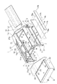
図1は、本発明の一実施形態を示す商品陳列台の斜視図、図2は、図1に示した商品陳列台の分解斜視図である。
Hereinafter, embodiments of the present invention will be described with reference to the drawings.
FIG. 1 is a perspective view of a product display stand showing an embodiment of the present invention, and FIG. 2 is an exploded perspective view of the product display stand shown in FIG.
本発明の商品陳列台は、陳列台本体1と、この陳列台本体1の内部空間内に格納される側端陳列台2とよりなる。
The merchandise display stand of the present invention includes a display stand
陳列台本体1は、平面視において、左右方向に長い長方形をなし、その各角部に4本の支持脚3が配置されている。前後の左右1対の支持脚3、3同士は、脚柱4の下端において、左右方向の横杆5により連結されている。脚柱4の下端には、キャスター6が取り付けられている。
The
脚柱4の上端には、前後方向の外側に向かう短寸の上端部材7が取り付けられ、前後の上端部材7、7間には、側面視において山形に組み付けされた支持部材8、8の下端が固定されている。左右の上端部材7、7は、左右方向の横杆7aで連結されている。前後の支持部材8、8は、前後方向の横杆9で連結されている。
A short
商品の陳列面10は、側面視山形状の左右の支持部材8,8間に、切妻屋根式の形状に傾斜させて設けられている。前後の傾斜する陳列面10は、それぞれ、上部、中部、下部の3枚の板部材11、12、14を組み付けて構成されている。
The
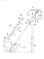
図3は、図1におけるIII〜III線拡大断面図である。
図2、図3に示すように、上部板部材11は、左右方向に長い帯状の鉄板の上端を下向きに鋭角に折り曲げて、上端の折り曲げ片11aとなすとともに、下端を下向きに直角に折り曲げ、その折り曲げ片11bの遊端を上向きの溝11cが形成されるように折り返し、かつ左右端を下向きに折り曲げて、左右端の折り曲げ片11dとなすことにより形成されている。
3 is an enlarged sectional view taken along line III to III in FIG.
As shown in FIGS. 2 and 3, the
中部板部材12は、上下端を下向きに直角に折り曲げて、折り曲げ片12a、12bとなし、その折り曲げ片12a、12bの遊端を内側に折り返すとともに、左右端を下向きに直角に折り曲げて折り曲げ片12cとなし、この左右の折り曲げ片12c、12c間に、断面コ字状の補強材13を、左右方向に2本配設して形成されている。
The
下部板部材14は、上端を下向きに直角に折り曲げ、その折り曲げ片14aの遊端を、上向きの溝14bが形成されるように折り返すとともに、下端を下向きに鋭角に折り曲げて折り曲げ片14cとなし、かつ左右端を、下向きに直角に折り曲げて左右端の折り曲げ片14dとなすことにより形成されている。
The
これらの上部、中部、下部の3枚の板部材11、12、14は、次のようにして組み付けされている。すなわち、中部板部材12の上端の折り返し端12dを、上部板部材11の下端の折り返し溝11cに、中部板部材12の下端の折り返し端12eを、下部板部材14の上端の折り返し溝14bに、それぞれ嵌合させて3枚の板部材11、12、14を組み付ける。
The three
次いで、これら2枚の板部材11、14の左右の折り返し片11d、14dにおける上下端近傍に穿設された通孔11e、14eに、図2に示すように、左右方向の内側からビス15a、15bを挿通して、支持部材8に止めることにより、3枚の板部材11、12、14の上面を傾斜する同一面上に配設して、陳列面10が形成されている。
Next, as shown in FIG. 2,
支持脚3の上端に取り付けられている左右の上端部材7、7を連結している横杆7aには、落下防止板16が、金具17aとビス17bをもって取り付けられている。
この落下防止板16は、陳列面10上に陳列された商品の落下を防止するためのものである。
A
The
左右の脚柱4、4間には、ビス18aをもって、幕板18が取り付けられている。
A
陳列台本体1の左右側端には、取付金具19とビス20をもって、落下防止壁21、21が取り付けられている。
落下防止壁21は側面視台形板状のもので、その上端部21aは、陳列面10より上方に突出している。
The
左側端の落下防止壁21の下縁には、陳列台本体1における陳列面10の下方の内部空間22内に格納されている側端陳列台2を出し入れするための扁平角形の上向凹入孔23が設けられている。
At the lower edge of the
図4は、側端陳列台2を前記上向凹入孔23から引き出して、陳列台本体1の側方に配置して使用状態としたときの斜視図、図5は、その正面図、図6は、左側面図である。
FIG. 4 is a perspective view when the side
図7は、陳列台本体1と側端陳列台2の陳列面10、25に、陳列用補助具26、27を載置したときの斜視図である。
FIG. 7 is a perspective view when the
側端陳列台2は、覆蓋付きの箱状に形成されており、その内部空間は、在庫商品等を収容しうるようになっているとともに、底部には、キャスター24が取り付けられている。
The side
覆蓋28の天板29の上面により、陳列面25が形成されており、覆蓋28の四方の側板30の上端30aは、陳列面25から上方に突出して、商品の落下防止の作用をなしうるようになっている。
The
商品は、陳列台本体1と側端陳列台2の陳列面10、25上に直接陳列してもよいが、図7に示すように、適宜の陳列用補助具26、27を陳列面10、25上に載置してから陳列してもよい。
The products may be displayed directly on the display surfaces 10 and 25 of the display table
側端陳列台2における箱状の内部空間は、前記陳列用補助具26、27の収容空間としても利用することができる。
The box-shaped internal space in the side
図1に示すように、側端陳列台2を、陳列台本体1における陳列面10の下方の内部空間22内に格納した際には、側端陳列台2の外側面2aにより、陳列台本体1の落下防止壁21の上向凹入孔23は閉塞され、かつ側端陳列台2の前記外側面2aと陳列台本体1の落下防止壁21とが、実質的に同一平面上に位置し、商品陳列台の側壁面を形成するようになっている。
As shown in FIG. 1, when the side
図8は、本発明の商品陳列台の別の実施形態を示す斜視図であり、図4に相当する図である。 FIG. 8 is a perspective view showing another embodiment of the commodity display stand of the present invention, and corresponds to FIG.
側端陳列台31が、陳列台本体32に引き出し可能に取り付けられている。陳列台本体32における陳列面33下方の内部空間34の前後内壁面に左右方向のレール35が取り付けられており、側端陳列台31の前後面に設けられた左右方向の滑杆32が、前記レール35に滑動自在に取り付けられて側端陳列台31が引き出し可能になっている。
The side end display stand 31 is attached to the display stand
側端陳列台31の支持脚36は、側端陳列台31の左端に設けられており、陳列台本体32側を支持する脚としては、陳列台本体32の支持脚37をもって兼用させてある。
The
このように、側端陳列台31を陳列台本体32に引き出し可能に取り付けることにより、側端陳列台31を引き出して、陳列台本体32の側方に配置する際の位置決めが容易となるばかりでなく、側端陳列台31が陳列台本体32と一体であるため、商品陳列台を移動する際にも、側端陳列台31を陳列台本体32と別途に移動する必要がない。
In this way, by attaching the side end display stand 31 to the display stand
1 陳列台本体
2 側端陳列台
2a 外側面
3 支持脚
4 脚柱
5 横杆
6 キャスター
7 上端部材
8 支持部材
9 横杆
10 陳列面
11 上部板部材
11a、11b 折り曲げ片
11c 折り返し溝
11d 折り曲げ片
11e 通孔
12 中部板部材
12a〜12c 折り曲げ片
12d、12e 折り返し端
13 補強材
14 下部板部材
14a 折り曲げ片
14b 折り返し溝
14c、14d 折り曲げ片
14e 通孔
15a、15b ビス
16 落下防止板
17a 金具
17b ビス
18 幕板
18a ビス
19 取付金具
20 ビス
21 落下防止壁
22 内部空間
23 上向凹入孔
24 キャスター
25 陳列面
26、27 陳列用補助具
28 覆蓋
29 天板
30 側板
30a 上端
31 側端陳列台
32 陳列台本体
33 陳列面
34 内部空間
35 レール
36、37 支持脚
DESCRIPTION OF
Claims (6)
Priority Applications (1)
| Application Number | Priority Date | Filing Date | Title |
|---|---|---|---|
| JP2007047482A JP2008206807A (en) | 2007-02-27 | 2007-02-27 | Merchandise display stand |
Applications Claiming Priority (1)
| Application Number | Priority Date | Filing Date | Title |
|---|---|---|---|
| JP2007047482A JP2008206807A (en) | 2007-02-27 | 2007-02-27 | Merchandise display stand |
Publications (1)
| Publication Number | Publication Date |
|---|---|
| JP2008206807A true JP2008206807A (en) | 2008-09-11 |
Family
ID=39783623
Family Applications (1)
| Application Number | Title | Priority Date | Filing Date |
|---|---|---|---|
| JP2007047482A Withdrawn JP2008206807A (en) | 2007-02-27 | 2007-02-27 | Merchandise display stand |
Country Status (1)
| Country | Link |
|---|---|
| JP (1) | JP2008206807A (en) |
Cited By (1)
| Publication number | Priority date | Publication date | Assignee | Title |
|---|---|---|---|---|
| JP2012210370A (en) * | 2011-03-31 | 2012-11-01 | Okamura Corp | Merchandise display fixture |
-
2007
- 2007-02-27 JP JP2007047482A patent/JP2008206807A/en not_active Withdrawn
Cited By (1)
| Publication number | Priority date | Publication date | Assignee | Title |
|---|---|---|---|---|
| JP2012210370A (en) * | 2011-03-31 | 2012-11-01 | Okamura Corp | Merchandise display fixture |
Similar Documents
| Publication | Publication Date | Title |
|---|---|---|
| US9474393B2 (en) | Mattress display fixture | |
| US9301603B1 (en) | Collapsible storage cabinet | |
| EP1996049B1 (en) | A blank for a rack | |
| JP2002058571A (en) | Auxiliary merchandise display stand | |
| JP2013031547A (en) | Storage box-folding display stand and method of using the same | |
| JP6336317B2 (en) | Product display fixtures | |
| KR20070107919A (en) | Assembly shelf that enables the display of goods with various heights regardless of the height interval of the multi-stage shelf | |
| JP5378740B2 (en) | Assembly structure of article storage | |
| KR200405541Y1 (en) | Mobile sales stand | |
| JP2019084006A (en) | Display rack | |
| JP5926967B2 (en) | Article display fixtures | |
| KR101614834B1 (en) | Foldable panel for decoration furniture | |
| JP3152338U (en) | Dual product display stand and double product display stand kit | |
| JP2004236988A (en) | Article display device | |
| JP5914711B1 (en) | Display fixtures | |
| JP2012210370A (en) | Merchandise display fixture | |
| JP5923321B2 (en) | Goods display shelf | |
| JP2005034463A (en) | Structure for reinforcing display shelf board | |
| JP7165387B2 (en) | Folding display stand and display stand set | |
| KR200316814Y1 (en) | display table to have a various variety | |
| JP4651301B2 (en) | Shelf board | |
| JP2008099854A (en) | Storage box and storage rack | |
| JP3170045U (en) | Product display shelf | |
| WO2011007724A1 (en) | Drawer-type supplemental display base for merchandise display fixture | |
| JP2007301216A (en) | Merchandise display furniture |
Legal Events
| Date | Code | Title | Description |
|---|---|---|---|
| A300 | Withdrawal of application because of no request for examination |
Free format text: JAPANESE INTERMEDIATE CODE: A300 Effective date: 20100511 |