JP2008080648A - Image forming device and its control method - Google Patents
Image forming device and its control method Download PDFInfo
- Publication number
- JP2008080648A JP2008080648A JP2006263258A JP2006263258A JP2008080648A JP 2008080648 A JP2008080648 A JP 2008080648A JP 2006263258 A JP2006263258 A JP 2006263258A JP 2006263258 A JP2006263258 A JP 2006263258A JP 2008080648 A JP2008080648 A JP 2008080648A
- Authority
- JP
- Japan
- Prior art keywords
- post
- image forming
- recording material
- processing
- forming apparatus
- Prior art date
- Legal status (The legal status is an assumption and is not a legal conclusion. Google has not performed a legal analysis and makes no representation as to the accuracy of the status listed.)
- Pending
Links
- 238000000034 method Methods 0.000 title claims description 22
- 238000012805 post-processing Methods 0.000 claims abstract description 140
- 239000000463 material Substances 0.000 claims abstract description 104
- 238000003860 storage Methods 0.000 claims abstract description 23
- 230000005540 biological transmission Effects 0.000 claims abstract description 19
- 238000007599 discharging Methods 0.000 claims description 11
- 230000003247 decreasing effect Effects 0.000 abstract 1
- 230000000452 restraining effect Effects 0.000 abstract 1
- 230000006870 function Effects 0.000 description 15
- 238000007639 printing Methods 0.000 description 13
- 238000010586 diagram Methods 0.000 description 10
- 238000012545 processing Methods 0.000 description 10
- 238000012546 transfer Methods 0.000 description 6
- 238000004026 adhesive bonding Methods 0.000 description 4
- 230000006835 compression Effects 0.000 description 3
- 238000007906 compression Methods 0.000 description 3
- 230000006837 decompression Effects 0.000 description 3
- 239000000284 extract Substances 0.000 description 3
- 230000014759 maintenance of location Effects 0.000 description 3
- 238000004891 communication Methods 0.000 description 2
- 239000003292 glue Substances 0.000 description 2
- 229910052736 halogen Inorganic materials 0.000 description 2
- 150000002367 halogens Chemical class 0.000 description 2
- 238000010438 heat treatment Methods 0.000 description 2
- 210000000707 wrist Anatomy 0.000 description 2
- 230000015572 biosynthetic process Effects 0.000 description 1
- 238000007796 conventional method Methods 0.000 description 1
- 238000005520 cutting process Methods 0.000 description 1
- 238000013479 data entry Methods 0.000 description 1
- 238000001514 detection method Methods 0.000 description 1
- 238000007645 offset printing Methods 0.000 description 1
- 230000003287 optical effect Effects 0.000 description 1
- 238000002360 preparation method Methods 0.000 description 1
- 238000004080 punching Methods 0.000 description 1
- 238000000926 separation method Methods 0.000 description 1
- 239000007787 solid Substances 0.000 description 1
- 239000011232 storage material Substances 0.000 description 1
- 230000007704 transition Effects 0.000 description 1
- 238000011144 upstream manufacturing Methods 0.000 description 1
Images


Classifications
-
- G—PHYSICS
- G03—PHOTOGRAPHY; CINEMATOGRAPHY; ANALOGOUS TECHNIQUES USING WAVES OTHER THAN OPTICAL WAVES; ELECTROGRAPHY; HOLOGRAPHY
- G03G—ELECTROGRAPHY; ELECTROPHOTOGRAPHY; MAGNETOGRAPHY
- G03G15/00—Apparatus for electrographic processes using a charge pattern
- G03G15/65—Apparatus which relate to the handling of copy material
- G03G15/6529—Transporting
-
- B—PERFORMING OPERATIONS; TRANSPORTING
- B41—PRINTING; LINING MACHINES; TYPEWRITERS; STAMPS
- B41J—TYPEWRITERS; SELECTIVE PRINTING MECHANISMS, i.e. MECHANISMS PRINTING OTHERWISE THAN FROM A FORME; CORRECTION OF TYPOGRAPHICAL ERRORS
- B41J13/00—Devices or arrangements of selective printing mechanisms, e.g. ink-jet printers or thermal printers, specially adapted for supporting or handling copy material in short lengths, e.g. sheets
- B41J13/0009—Devices or arrangements of selective printing mechanisms, e.g. ink-jet printers or thermal printers, specially adapted for supporting or handling copy material in short lengths, e.g. sheets control of the transport of the copy material
-
- B—PERFORMING OPERATIONS; TRANSPORTING
- B41—PRINTING; LINING MACHINES; TYPEWRITERS; STAMPS
- B41J—TYPEWRITERS; SELECTIVE PRINTING MECHANISMS, i.e. MECHANISMS PRINTING OTHERWISE THAN FROM A FORME; CORRECTION OF TYPOGRAPHICAL ERRORS
- B41J13/00—Devices or arrangements of selective printing mechanisms, e.g. ink-jet printers or thermal printers, specially adapted for supporting or handling copy material in short lengths, e.g. sheets
- B41J13/10—Sheet holders, retainers, movable guides, or stationary guides
-
- G—PHYSICS
- G03—PHOTOGRAPHY; CINEMATOGRAPHY; ANALOGOUS TECHNIQUES USING WAVES OTHER THAN OPTICAL WAVES; ELECTROGRAPHY; HOLOGRAPHY
- G03G—ELECTROGRAPHY; ELECTROPHOTOGRAPHY; MAGNETOGRAPHY
- G03G15/00—Apparatus for electrographic processes using a charge pattern
- G03G15/50—Machine control of apparatus for electrographic processes using a charge pattern, e.g. regulating differents parts of the machine, multimode copiers, microprocessor control
- G03G15/5004—Power supply control, e.g. power-saving mode, automatic power turn-off
Abstract
Description
本発明は、給紙装置、後処理装置及び画像形成装置を含む画像形成システム及びその制御方法に関する。 The present invention relates to an image forming system including a paper feeding device, a post-processing device, and an image forming device, and a control method thereof.
近年、電子写真方式やインクジェット方式の画像形成装置の画像品質は、オフセット印刷の画像品質に迫ってきているため、商業印刷の分野でも当該画像形成装置の導入が盛んである。 In recent years, the image quality of electrophotographic and ink jet image forming apparatuses has approached that of offset printing, and therefore, such image forming apparatuses are actively introduced in the field of commercial printing.
一方、商業印刷の分野では、オンデマンドプリントが注目されている。オンデマンドプリントは、顧客から通信回線を通して送信される印刷データに基づいて実行される印刷処理をいう。オンデマンドプリントは、多品種、小ロットの需要にも柔軟に応えることができるため、例えば、マニュアル等のドキュメントや個人向けパンフレットの印刷にも適している。また、印刷在庫の大幅な削減、オンラインでデータ入力から製本完了まで可能となることによる大幅な工数時間の短縮、データ転送の容易さなどからも、オンデマンドプリントは利点が多い。 On the other hand, on-demand printing has attracted attention in the field of commercial printing. On-demand printing refers to a printing process that is executed based on print data transmitted from a customer through a communication line. Since on-demand printing can flexibly meet the demand for various types and small lots, it is suitable for printing documents such as manuals and personal pamphlets, for example. In addition, on-demand printing has many advantages because it greatly reduces printing inventory, significantly reduces man-hours by enabling online data entry to bookbinding, and ease of data transfer.
ところで、オンデマンドプリントに使用される画像形成システムは、多種多様な記録材に対応するために、複数の大容量の給紙装置が接続される。また、帳合い、仕分け、Z折り処理、インサータ処理、ステイプル処理、パンチ穴あけ処理、製本処理などの後処理を実現するには、複数の後処理装置が必要となる。 Incidentally, an image forming system used for on-demand printing is connected to a plurality of large-capacity paper feeding devices in order to cope with a wide variety of recording materials. Also, a plurality of post-processing devices are required to realize post-processing such as bookkeeping, sorting, Z-folding processing, inserter processing, stapling processing, punch punching processing, and bookbinding processing.
しかしながら、複数の給紙装置や複数の後処理装置の全てを一斉に動作させたり、停止させたりすると、無駄なエネルギーが消費されたり、騒音が大きくなったりするため、好ましくない。 However, if all of the plurality of paper feeding devices and the plurality of post-processing devices are simultaneously operated or stopped, useless energy is consumed and noise is increased, which is not preferable.
従来、各後処理装置が、各用紙の行き先情報に応じて、自機に所定枚数以上の用紙が搬送されないと判断すると、自律的に動作を停止する発明が提案されている(特許文献1)。
しかし、複数の後処理装置には、一度、動作を停止してしまうと、再開のための準備動作を必要とする後処理装置が含まれる場合がある。従って、各後処理装置が、勝手に動作を停止してしまうと、画像形成システムのスループットが低下してしまうおそれがある。また、特許文献1の画像形成システムは、各後処理装置が、自機に所定枚数の用紙が到着するのを必ず待ってから停止する。そのため、所定枚数の用紙の到着を待つ必要がないときには、スループットが低下してしまう。なお、特許文献1は、後処理装置には着目しているが、給紙装置には着目していない。
However, the plurality of post-processing devices may include a post-processing device that requires a preparatory operation for restarting once the operation is stopped. Therefore, if each post-processing device stops operation without permission, the throughput of the image forming system may be reduced. In addition, the image forming system disclosed in
そこで、本発明は、スループットの低下を緩和しつつ、電力消費の削減及び低騒音化を実現可能な画像形成システムを提供することを目的とする。 SUMMARY An advantage of some aspects of the invention is that it provides an image forming system capable of reducing power consumption and reducing noise while reducing a decrease in throughput.
本発明は、例えば、画像形成装置システムとして実現できる。画像形成システムは、記録材に画像を形成する画像形成装置と、画像形成装置からの記録材に後処理を施す複数の後処理装置とを含む。また、画像形成装置は、複数の後処理装置の接続順序を記憶する記憶手段と、記録材を排出するための後処理装置を指定する指定情報と複数の後処理装置の接続順序に応じて、動作の開始要求又は終了要求が通知されるべき後処理装置を決定する決定手段を含む。さらに、画像形成装置は、決定された後処理装置へ動作の開始要求又は動作の終了要求を送信する送信手段を含む。 The present invention can be realized, for example, as an image forming apparatus system. The image forming system includes an image forming apparatus that forms an image on a recording material, and a plurality of post-processing devices that perform post-processing on the recording material from the image forming apparatus. The image forming apparatus includes a storage unit that stores a connection order of a plurality of post-processing devices, designation information that specifies a post-processing device for discharging recording materials, and a connection order of the plurality of post-processing devices. A determination unit configured to determine a post-processing device to be notified of an operation start request or an end request; Further, the image forming apparatus includes a transmission unit that transmits an operation start request or an operation end request to the determined post-processing apparatus.
なお、画像形成装置システムは、記録材を画像形成装置へ給紙するか又は先行する後処理装置からの記録材を搬送する複数の給紙装置を含んでもよい。この場合、画像形成装置は、複数の給紙装置の接続順序を記憶する記憶手段と、記録材を給紙するための給紙装置を指定する指定情報と複数の給紙装置の接続順序に応じて動作の開始要求又は終了要求が通知されるべき給紙装置を決定する決定手段を含んでもよい。 The image forming apparatus system may include a plurality of sheet feeding apparatuses that feed the recording material to the image forming apparatus or transport the recording material from the preceding post-processing apparatus. In this case, the image forming apparatus corresponds to the storage unit that stores the connection order of the plurality of sheet feeding apparatuses, the designation information that specifies the sheet feeding apparatus for feeding the recording material, and the connection order of the plurality of sheet feeding apparatuses. And determining means for determining a sheet feeding device to be notified of an operation start request or an end request.
本発明によれば、画像形成装置が、後処理装置や給紙装置の接続順序と、排出装置となる後処理装置や実際に給紙を行う給紙装置に応じて、動作の開始要求又は終了要求が通知されるべき装置を決定する。とりわけ、画像形成装置は、各印刷ジョブを管理しているため、後処理装置や給紙装置の動作開始や停止のタイミングをより好適に決定できる。よって、本発明は、各後処理装置が、自律的に動作の開始と停止を決定する従来技術と比較して、スループットの低下を緩和しつつ、電力消費の削減及び低騒音化を実現できる。 According to the present invention, the image forming apparatus is requested to start or end the operation according to the connection order of the post-processing apparatus and the paper feeding apparatus, the post-processing apparatus as the discharge apparatus, and the paper feeding apparatus that actually feeds paper. Determine the device to which the request should be notified. In particular, since the image forming apparatus manages each print job, it is possible to more suitably determine the timing for starting and stopping the operations of the post-processing apparatus and the paper feeding apparatus. Therefore, according to the present invention, it is possible to reduce power consumption and reduce noise while alleviating the decrease in throughput as compared with the prior art in which each post-processing device autonomously determines the start and stop of operation.
以下に本発明の一実施形態を示す。もちろん以下で説明される個別の実施形態は、本発明の上位概念、中位概念及び下位概念など種々の概念を理解するために役立つであろう。また、本発明の技術的範囲は、特許請求の範囲によって確定されるのであって、以下の個別の実施形態によって限定されるわけではない。 An embodiment of the present invention is shown below. Of course, the individual embodiments described below will be helpful in understanding various concepts, such as the superordinate concept, intermediate concept and subordinate concept of the present invention. Further, the technical scope of the present invention is determined by the scope of the claims, and is not limited by the following individual embodiments.
[実施形態1]
図1は、実施形態に係る画像形成システム例示的な断面図である。1は、画像形成装置である。2、3、4は、記録材Pを格納する給紙装置である。なお、記録材は、記録媒体、用紙、シート、転写材、転写紙と呼ばれることもある。5、6、52は、記録材を積載するスタッカーである。7は、フィニッシャーである。なお、スタッカー5、6、52及びフィニッシャー7は、いわゆる後処理装置の一例である。
[Embodiment 1]
FIG. 1 is an exemplary cross-sectional view of an image forming system according to an embodiment.
画像形成装置1は、例えば、次のような構成要素を備えている。感光ドラム29は、潜像やトナーによる可視画像を担持する。一次帯電器22は、感光ドラムを一様に帯電させる。露光器20は、光信号に変換された画像データを感光ドラム29に照射する。現像器21は、感光ドラム29上に形成された潜像をトナーによって可視画像に変換する。転写帯電器24は、感光ドラム29上に形成されたトナー像を記録材に転写する。分離帯電器25は、記録材を感光ドラムから引き離すための高電圧を印加する。クリーナ23は、転写されずに感光ドラム29上に残ったトナーを回収する。
The
給紙装置2、3、4は、それぞれ次の構成要素を備えている。収納庫12、11、10は、記録材を積載しつつ収納する。給紙ローラ9、8、19は、積載されている記録材を1枚ずつ分離して給紙する。リフター15、14、13、記録材の紙面高さを給紙ローラ9、8、19が給紙できる適正な位置に調整する。搬送ローラ18、17、16は、収納庫又は先行する(上流の)給紙装置からの記録材を搬送する。
Each of the
ところで、給紙装置2、3、4は、ヒータ(図示略)によって暖められた空気を収納庫12、11、10内に送り込むブロワー(図示略)をそれぞれ有している。これにより、収納庫12、11、10内の湿度が調節される。なお、湿度調節制御は、記録材の素材によって異なる。例えば、坪量が64g/m2〜105g/m2程度の普通紙は、湿度調整制御が必要ない。一方、坪量が105g/m2を越える厚紙に対しては湿度調節が必要となる。また、ヒータが目的の温度に達しない給紙装置2、3、4からは、記録材を搬送することができない。そのため、給紙装置2、3、4に積載された記録材の素材などのパラメータに依存して、電源ONや動作開始の指示があってから、実際に搬送動作を開始できるまでの時間は変化することになる。
By the way, each of the
給紙装置2、3、4から給紙された記録材は、記録材検知センサ27によって画像形成装置1への到着が検知される。記録材は、レジストローラ26に突き当たることでスキューが補正される。さらに、記録材は、転写帯電器24に搬送されてトナー像が転写される。その後、記録材は、搬送ベルト28によって定着ローラ31が存在する方向に搬送される。定着ローラ31は、一対のローラから構成される。対となっている定着ローラの上側のローラにはハロゲンヒータ32が内蔵されている。また、上側のローラの近傍には、定着ローラの温度を検知するためのサーミスタ30が配置されている。ハロゲンヒータ32によって、定着ローラ31の温度が、約摂氏180度程度に維持されている。定着ローラ31を通過した記録材は、画像形成装置1に直接属されている後処理装置の一例であるスタッカー5に搬送される。
The recording material fed from the
スタッカー5、6、52は、それぞれ、次のような構成要素を備えている。収納庫36、38、47は、記録材を収納する。積載トレイ35、39、46は、収納庫36、38、47の記録材を積載する。搬送ローラ33、37、45は、サンプルトレイ、収納庫又は後続の後処理装置へ記録材を搬送する。サンプルトレイ49、50、51は、サンプルとして印刷された記録材など、少数の記録材を積載する。フラッパー34、40、48は、記録材の搬送経路を切り替える。搬送経路としては、それぞれのスタッカーにおいて、収納庫へ積載する経路、下流(後続)の後処理装置へ記録材を搬送する経路、及び記録材をサンプルトレイへ積載する経路の3つが存在する。
Each of the
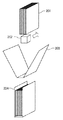
フィニッシャー7は、記録材を積載するための排出トレイ41を備えている。記録材は搬送経路43を通って排出トレイ41に積載される。一方、フィニッシャー7の断面図中に点線で囲まれた部分は、くるみ製本ユニット42である。くるみ製本ユニット42は、搬送経路44を経由して搬送された記録材をくるみ製本する。
The
図2は、くるみ製本を説明するための図である。例えば、複数のA4サイズの記録材からなる束201の背に、糊付けユニット202が糊付けを行う。そして、A3サイズの表紙203で糊付けされた束201がくるまれ、束204が形成される。束204は、不図示の截断ユニットにより、所定サイズとなるように裁断される。なお、表紙203を束201と接着するための糊は、一般に、常温で固形である。よって、糊付けする際には、糊は、ヒータ等によって加熱される必要があるが、通常、加熱には、数分間が必要である。これは、一度、ヒータの加熱を停止すれば、再び、糊付けユニット202を所望の温度へ加熱するには、ある程度の待ち時間が発生することを意味する。
FIG. 2 is a diagram for explaining case binding. For example, the gluing
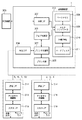
図3は、実施形態に係る制御部の一例を示すブロック図である。306は、画像形成装置1に対してプリントジョブなどを送信する、パーソナルコンピュータ(PC)や画像読取装置などの外部装置である。プリントジョブとは、画像データと印刷データを含む。一般に、印刷データは、記録材を排出するための後処理装置を指定する指定情報、記録材を給紙するための給紙装置を指定する指定情報などを含む。
FIG. 3 is a block diagram illustrating an example of a control unit according to the embodiment.
外部装置306から送信されたプリントジョブは、画像形成装置1の外部I/F307で受信される。外部I/F307で受信されたプリントジョブはメモリコントローラ309に送られる。メモリコントローラ309は、プリントジョブから画像データを抽出し、圧縮/伸張部310へ送る。画像データは圧縮されているので、圧縮・伸張部310は、画像データを内部的なデータに変換する。内部的なデータに変換された画像データは、ハードディスク311に格納される。ハードディスク311は、大容量の他の記憶手段によって構成することも可能である。なお、ハードディスク311は、複数の後処理装置の接続順序や複数の給紙装置の接続順序を記憶する。
A print job transmitted from the
一方、メモリコントローラ309は、プリントジョブに含まれる印刷データを抽出してジョブ制御部301へ送る。ジョブ制御部301は、印刷データを受信すると、印刷動作を開始すべく、プリント制御部302へ動作開始要求を送信する。プリント制御部302は、動作開始要求を受信すると、プリンタ部303へ動作開始要求を送信するとともに、印刷データにより指定された給紙装置や後処理装置に対してアクセサリ(ACC)I/F304を介して動作の開始要求を送信する。すなわち、アクセサリI/F304は、動作の開始要求などの通知を送信する送信手段として機能する。なお、アクセサリは、給紙装置や後処理装置など、画像形成装置1に接続される装置の総称である。
On the other hand, the
その際に、プリント制御部302は、記録材を排出するための後処理装置を指定する指定情報と、複数の後処理装置の接続順序とに応じて、動作の開始要求が通知されるべき後処理装置を決定する決定手段として機能する。また、プリント制御部302は、記録材を給紙するための給紙装置を指定する指定情報と、複数の給紙装置の接続順序とに応じて、動作の開始要求又は動作の終了要求が通知されるべき給紙装置を決定する決定手段として機能する。
At that time, the
なお、給紙装置や後処理装置は、必ずしも同一の機能を実現するものではないが、電気的な制御部は、ほぼ同様の構成を採用することも可能である。そこで、説明を簡潔にするために、給紙装置や後処理装置の制御部は、同様の構成を採用しているものとする。 Note that the sheet feeding device and the post-processing device do not necessarily realize the same function, but the electrical control unit can adopt almost the same configuration. Therefore, for the sake of brevity, it is assumed that the control unit of the paper feeding device or the post-processing device adopts the same configuration.
通信I/F314は、画像形成装置1から送信された動作開始要求等のコマンドを受信したり、何らかの情報を画像形成装置1へ送信したりする。入出力I/F318は、モータ等の負荷を駆動したり、センサ信号を受信したりするためのユニットである。アクセサリ制御部316は、画像形成装置1や隣接する他の装置と通信を行う。給紙装置に搭載されるアクセサリ制御部316は、例えば、記録材の搬送を制御したり、給紙を制御したりする。また、後処理装置に搭載されるアクセサリ制御部316は、記録材の搬送を制御したり、後処理を制御したりする。
画像形成装置1のプリンタ部303は、画像形成装置1の記録材に画像を形成するユニットである。プリンタ部303、プリントジョブに関与する給紙装置及び後処理装置の各動作準備が終了すると、ジョブ制御部301は、画像データをページ毎に出力するようメモリコントローラ309に要求する。メモリコントローラ309は、ハードディスク311から内部的なデータに変換された画像データを読み出する。圧縮/伸張部310は、読み出された画像データを画像形成装置1において印字可能なビットマップデータに伸張し、ページメモリ308に格納する。ジョブ制御部301は、メモリコントローラ309から送られてきたビットマップデータを、プリント制御部302を介してプリンタ部303に送信する。プリント制御部302は、プリンタ部303に画像形成の実施を指示する。さらに、プリント制御部302は、指定された給紙装置に記録材の搬送開始を指示する。また、プリント制御部302は、記録材の搬送経路に位置する各後処理装置に、アクセサリI/F304を介して記録材の情報を送信する。
The communication I /
The printer unit 303 of the
プリントジョブが終了すると、ジョブ制御部301は、プリント制御部302に動作終了を指示する。プリント制御部302は、必要に応じて、アクセサリI/F304を介して給紙装置や後処理装置に動作の終了要求を送信する。すなわち、アクセサリI/F304は、動作の終了要求などの通知を送信する送信手段として機能する。
When the print job ends, the
その際に、プリント制御部302は、記録材を排出するための後処理装置を指定する指定情報と、複数の後処理装置の接続順序とに応じて、動作の終了要求が通知されるべき後処理装置を決定する決定手段として機能する。同様に、プリント制御部302は、記録材を給紙するための給紙装置を指定する指定情報と、複数の給紙装置の接続順序とに応じて、動作の終了要求が通知されるべき給紙装置を決定する決定手段として機能する。また、プリント制御部302は、プリンタ部303に対して動作終了を指示する。
At that time, the
なお、プリント制御部302がプリントジョブを実行中に、次のプリントジョブが外部装置306から到来することもある。この場合、ジョブ制御部301は、メモリコントローラ309を介して画像データをハードディスク311に格納し、印刷データをジョブ制御部301が備えるRAM(不図示)に記憶する。なお、印刷データもハードディスク311に記憶されてもよい。このように、RAMやハードディスク311は、記憶手段として機能する。そして、ジョブ制御部301は、前のプリントジョブが終了すると、順次、次のプリントジョブを実行する。
図4は、実施形態に係るプリントジョブのデータ構造の一例を示す図である。プリントジョブは、ページごとにデータが分かれている。よって、プリントジョブは、印刷されるページ数に対応した数のページデータからなる。例えば、3ページを印刷するためのプリントジョブは、3つのページデータを有する。ページデータの構造はいずれも同一であるため、ページデータ400を一例として説明する。
Note that the next print job may arrive from the
FIG. 4 is a diagram illustrating an example of a data structure of a print job according to the embodiment. In the print job, data is divided for each page. Therefore, the print job includes a number of page data corresponding to the number of pages to be printed. For example, a print job for printing three pages has three page data. Since the page data has the same structure, the
ページデータ400の先頭には、ジョブ名称を格納するためのジョブ名称領域401が設けられている。ジョブ名称は、例えば、他のプリンジョブと区別するための識別情報(ID)などである。ページID領域402には、他のページと区別が可能な固有のページIDが格納される。給紙段ID領域403は、記録材を給紙する給紙装置を指定する指定情報の一例である給紙段IDが格納される。排出先ID領域404には、記録材を排出する後処理装置を指定するための指定情報の一例である排出先ID404が格納される。最終紙フラグ405は、本プリントデータに対応するページがプリントジョブの最後ページであるか否かを示す情報が格納される。先頭紙フラグ406は、本プリントデータに対応するページがプリントジョブの先頭ページであるか否かを示す情報が格納される。動作モード領域410は、プリントジョブに適用される動作モードを表す動作モード情報が格納される。動作モードには、例えば、通常動作、通常動作を中断して実行される優先順位の高いジョブを実行する動作(割り込み動作)、同一のジョブだが、排出先をサンプルトレイに替えて一部だけ出力する動作(プルーフプリント)などがある。なお、ページデータ400のうち、画像データ407を除くデータが上述の印刷データに相当する。
A
図5Aは、実施形態に係る排出経路リストの一例を示す図である。本実施形態では、記録材の排出先となるトレイが8段ある。よって、排出先IDは、1ないし8となる。具体的には、画像形成装置1の隣に配置されているスタッカー5のサンプルトレイ49の排出先IDが1となる。スタッカー5の収納庫36の排出先IDが2となる。スタッカー6のサンプルトレイ50の排出先IDが3となる。スタッカー6の収納庫38の排出先IDが4となる。スタッカー52のサンプルトレイ51の排出先IDが5となる。スタッカー52の収納庫47の排出先IDが6となる。フィニッシャー7の排出トレイ41の排出先IDが7となる。フィニッシャー7のくるみ積載トレイの排出先IDが8となる。
FIG. 5A is a diagram illustrating an example of a discharge route list according to the embodiment. In this embodiment, there are eight trays to which recording materials are discharged. Therefore, the discharge destination ID is 1 to 8. Specifically, the discharge destination ID of the sample tray 49 of the
さらに、排出先IDが1、2の場合、記録材は、画像形成装置1からスタッカー5に排出される。排出先IDが3、4の場合、記録材は、スタッカー5を経由してスタッカー6に搬送され、排出先IDに応じたトレイに排出される。排出先IDが5、6の場合、記録材は、スタッカー5、スタッカー6を経由してスタッカー52に搬送され、排出先IDに応じたトレイに排出される。排出先IDが7、8の場合、記録材は、スタッカー5、スタッカー6、スタッカー52を経由してフィニッシャー7に搬送され、排出先IDに応じたトレイに排出される。なお、排出経路リストの排出経路の欄に記載されている数字は、後処理装置を識別するための装置IDである。このように、複数の後処理装置の接続順序が排出経路として管理されている。なお、給紙装置に関しても接続順序を管理するデータやリストがハードディスク311などの格納されていてもよい。
Further, when the discharge destination ID is 1 or 2, the recording material is discharged from the
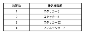
図5Bは、実施形態に係る装置ID管理リストの一例を示す図である。この図によれば、スタッカー5の装置IDは、1である。スタッカー6の装置IDは、2である。スタッカー52の装置IDは、3である。フィニッシャー7の装置IDは、4である。なお、図5Aと図5Bからわかるように、排出経路は、装置IDによって定義されている。
FIG. 5B is a diagram illustrating an example of a device ID management list according to the embodiment. According to this figure, the device ID of the
なお、装置ID管理リストや排出経路リストは、例えば、画像形成装置1の起動時に、プリント制御部302が、各後処理装置及び各給紙装置と通信することで作成する。
The apparatus ID management list and the discharge path list are created by the
なお、排出先IDと排出経路の関係は、図4で説明したプリントジョブのデータ構造には含まれていない。そのため、予め、画像形成装置1のハードディスクなどに記憶しておく必要がある。このように、複数の後処理装置が画像形成装置に接続されている場合、シートごとに、どの後処理装置へ排出されるのかを、画像形成装置1は把握している必要がある。
The relationship between the discharge destination ID and the discharge route is not included in the data structure of the print job described with reference to FIG. Therefore, it is necessary to store in advance in the hard disk of the
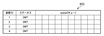
図6は、実施形態に係る後処理装置のステータスを管理するためのステータスリストの一例を示す図である。ステータスリスト600は、例えば、ジョブ制御部301により作成され、RAM又はハードディスク311に格納される。
FIG. 6 is a diagram illustrating an example of a status list for managing the status of the post-processing apparatus according to the embodiment. For example, the
装置IDの領域には、各後処理装置に割り当てられた装置IDが格納される。ステータスの領域には、各後処理装置ごとに、動作状態か、非動作状態かを示す情報が格納される。例えば、動作状態の場合「ACT」が格納され、非動作状態の場合「DMT」が格納される。Queue(キュー)の領域には、ページID(図4)が格納される。ジョブ制御部301は、プリントジョブを受信すると、そのページデータ400からページIDと排出先IDを抽出する。さらに、ジョブ制御部301は、排出先IDから排出経路を特定し、さらに排出経路の最後に位置する装置IDを特定する。ジョブ制御部301は、プリント制御部及びアクセサリI/F304を介して、装置IDに対応する後処理装置からステータス情報を取得する。最終的に、ジョブ制御部301は、ステータスリスト600に、装置ID、ステータス及びページIDを登録する。
The device ID assigned to each post-processing device is stored in the device ID area. In the status area, information indicating whether the post-processing apparatus is in an operating state or a non-operating state is stored. For example, “ACT” is stored in the operation state, and “DMT” is stored in the non-operation state. The page ID (FIG. 4) is stored in the Queue area. When receiving a print job, the
図7は、実施形態に係る画像形成装置の制御方法の一例を示すフローチャートである。当該フローチャートを参照しながら、画像形成装置1が、どのように後処理装置に対し、動作の開始と終了を制御するかについて説明する。
ステップS701で、ジョブ制御部301は、外部装置306からのコマンド(プリントジョブ)の到来を待つ。コマンドが到来すると、S702へ進む。ステップS702で、ジョブ制御部301は、受信したプリントジョブのページデータ400から排出先IDを読み出し、排出経路リスト(図5A)と照らし合わせて後処理装置の装置IDと排出経路を特定する。ジョブ制御部301は、記録材を排出するための後処理装置を指定する指定情報(例:排出先ID、装置ID)と、複数の後処理装置の接続順序とに応じて排出経路を決定する排出経路決定手段として機能する。
FIG. 7 is a flowchart illustrating an example of a control method of the image forming apparatus according to the embodiment. How the
In step S <b> 701, the
ステップS703で、ジョブ制御部301は、ページデータから抽出したページIDを、ステータスリストのqueueに格納する。ステップS704で、ジョブ制御部301は、排出経路リストを参照し、決定された排出経路に存在する1以上の後処理装置を、動作の開始要求が送信されるべき後処理装置として決定する。さらに、ジョブ制御部301は、排出経路リストを参照し、排出経路の最初に位置する後処理装置も決定する。例えば、排出経路が「1⇒2⇒3」であれば、装置IDを1に設定されている後処理装置が、最初の後処理装置となる。このように、ジョブ制御部301は、動作の開始要求が送信されるべき後処理装置を決定する送信先決定手段としても機能する。
In step S703, the
ステップS705で、ジョブ制御部301は、排出経路に存在するi(iは自然数。)番目の後処理装置のステータスをステータスリストから読み出す。なお、予めステータスリストはジョブ制御部301によって作成されているものとする。なお、ステップS705で、各後処理装置からステータスが直接的に取得されてもよい。
In step S <b> 705, the
ステップS706で、ジョブ制御部301は、読み出したステータスが「ACT」であるか否かを判定する。ステータスが動作中を意味する「ACT」であれば、ステップS707へ進む。一方、ステータスが非動作中を意味する「DMT」であれば、ステップS710へ進む。
In step S <b> 706, the
ステップS707で、ジョブ制御部301は、次ページのページデータから排出先IDを読み出し、排出経路リストに基づいて排出経路を決定し、ステータスを読み出した後処理装置が排出経路に含まれているかを判定する。排出経路に含まれていなければステップS708へ進み、含まれていればステップ712へ進む。
In step S707, the
ステップS708で、ジョブ制御部301は、受信したページデータから動作モードを読み出し、読み出した動作モードが継続モードか否かを判定する。継続モードは、例えば、割り込み動作、プルーフプリント及び通常動作において残りページ存在する場合などである。例えば、ジョブ制御部301は、さらに次のページデータを調べ、現在の処理対象となっているページが最終紙か否かを確認する。最終紙であれば、動作が終了するため、継続モードではない。継続モードであれば、ステップS712へ進む。一方、通常動作など、継続モードでなければ、ステップS709に進む。
In step S708, the
ステップS709で、ジョブ制御部301は、現在の処理対象となっている後処理装置に対して、動作の終了要求を意味するコマンドを送信する。そして、S712へ進む。
In step S709, the
このように、ジョブ制御部301は、決定された排出経路に存在しない後処理装置を、動作の終了要求が送信されるべき後処理装置として決定し、動作の終了要求を送信する。また、決定された排出経路に存在しない後処理装置であっても、後続の記録材に依拠する特定の条件が満たされていないときもある。よって、ジョブ制御部301は、当該後処理装置には、動作の終了要求が送信されないよう制御する。すなわち、継続モードにあると判定することで、動作の終了要求が送信されてしまうことを回避している。
In this way, the
一方、現在の処理対象となっている後処理装置が「DMT」である場合、S710で、ジョブ制御部301は、「DMT」の後処理装置が排出経路に位置するか否かを判定する。もし、排出経路に位置する後処理装置が動作していない場合、記録材のジャムが発生してしまう。よって、これを避けるために、当該後処理装置に対して、動作の開始要求を送信しなければならない。なお、排出経路の決定方法は、上述したとおりである。排出経路に「DMT」の後処理装置が存在しなければ、ステップS712へ進む。
On the other hand, if the post-processing device currently being processed is “DMT”, in step S710, the
一方、排出経路に「DMT」の後処理装置が存在する場合、ステップS711へ進む。S711で、ジョブ制御部301は、当該後処理装置に対して動作の開始要求を意味するコマンドを送信する。その後、S712へ進む。
On the other hand, when the “DMT” post-processing device exists in the discharge path, the process proceeds to step S711. In step S <b> 711, the
フローチャート上において、S707、S708、S709、S710及びS711の次のステップとなるS712で、ジョブ制御部301は、処理対象となる次の後処理装置が存在するか否かを判定する。次の後処理装置が存在すれば、ステップS713へ進み、ジョブ制御部301は、処理対象となる後処理装置の装置IDを次の後処理装置の装置IDにセットする。その後、ステップS705へ戻り、S705乃至S713からなる処理ループが実行される。
In step S712, which is the next step of steps S707, S708, S709, S710, and S711, the
図8は、プリントジョブの一例を示す図である。図8に示されるプリントジョブが外部装置306から送信されてきた際における、ステータスリストの変遷について説明する。図8のページIDに着目すると、このプリントジョブによって、10ページが印刷されることがわかる。
FIG. 8 is a diagram illustrating an example of a print job. The transition of the status list when the print job shown in FIG. 8 is transmitted from the
図9は、動作の開始から終了までの各後処理装置におけるイベントを示すイベントフローチャートである。図10Aないし10Jは、各イベントに対応するステータスリストを示している。当初、各後処理装置の状態は、図6に示すように、DMT(非動作状態)であるとする。 FIG. 9 is an event flowchart showing events in each post-processing apparatus from the start to the end of the operation. 10A to 10J show status lists corresponding to each event. Initially, the state of each post-processing apparatus is assumed to be DMT (non-operating state) as shown in FIG.
S901で、ページID=1の記録材についてページデータが外部装置306から到来する。排出先IDが7であるため、排出経路リストから、排出経路が1→2→3→4と決定される。
In step S <b> 901, page data for the recording material with page ID = 1 arrives from the
S902で、画像形成装置1は、排出経路に位置する各後処理装置に対して「動作の開始要求」を意味するコマンドを送信する。このとき、各後処理装置のqueueに、ページID=1が登録される。また、各後処理装置のステータスが「ACT」に変更される。このときのステータスが、図10Aに示されている。
In step S <b> 902, the
S903で、ページID=2のページデータが外部装置306から到来すると、図10Bに示されたステータスとなる。さらに、S904で、ページID=3のページデータが到来すると、図10Cに示されたステータスとなる。
In S903, when the page data of page ID = 2 arrives from the
S905で、ページID=4のページデータが到来する。このページデータの排出先IDは1であるため、スタッカー6、52及びフィニッシャー7に対して「終了要求」を送信可能な状態となる。しかし、ページデータの動作モードが「割り込み動作」に設定されているため(図8)、画像形成装置1は、「終了要求」を送信しない。このときのステータスは、図10で示したとおりとなる。
In S905, page data with page ID = 4 arrives. Since the discharge destination ID of this page data is 1, “end request” can be transmitted to the
S906で、排出先ID=1かつページID=5のページデータが到来すると、ステータスは、図10Eで示されたとおりとなる。S907で、ページID=6のページデータが到来する。なお、ページID=6に対応するページは、先ほどのページID=1、2、3に対応するページの続きである。本実施形態によれば、スタッカー6、52及びフィニッシャー7が動作状態「ACT」であるため、すぐさま、記録材を搬送することが可能となる。よって、この段階で、開始要求を送信する必要があった従来技術と比較すると、スループットが向上する。なお、このときのステータスは、図Fに示したとおりとなる。
In S906, when the page data of the discharge destination ID = 1 and the page ID = 5 arrives, the status becomes as shown in FIG. 10E. In S907, page data with page ID = 6 arrives. The page corresponding to page ID = 6 is a continuation of the pages corresponding to page IDs = 1, 2, and 3 described above. According to this embodiment, since the
S908で、ページID=7のページデータが到来する。ページデータによれば、このページは、最終紙である(図8)。よって、ページID=7に対応する記録材がフィニッシャー7のトレイに排出されると、S909で、画像形成装置1は、フィニッシャー7に「終了要求」を送信する。このときの、ステータスは、図10Gにより示されたとおりとなる。
In S908, page data with page ID = 7 arrives. According to the page data, this page is the last sheet (FIG. 8). Therefore, when the recording material corresponding to the page ID = 7 is discharged to the tray of the
S910で到来するページID=8のページデータ、S911で到来するページID=9のページデータは、それぞれ排出先IDが5に設定されている。排出先ID=5は、スタッカー52のサンプルトレイを意味する。このときのステータスは、図10H、10Iにより示されたとおりとなる。スタッカー52のサンプルトレイへの排出が完了すると、S912で、画像形成装置1は、スタッカー52に対して「終了要求」を送信する。
The page ID = 8 page data arrived at S910 and the page data = 9 page data arrived at S911 have a discharge destination ID set to 5, respectively. The discharge destination ID = 5 means the sample tray of the
S913で、ページID=10のページデータが到来する。当該ページデータの排出先IDは4である。これは、スタッカー6のスタックトレイへの排出を意味する。また、当該ページデータによれば、最終紙であることもわかる(図8)。よって、ページID=10の記録材の排出が完了すると、S914で、画像形成装置1は、スタッカー5に「終了要求」を送信する。さらに、S914で、画像形成装置1は、スタッカー6に「終了要求」を送信する。このときのステータスは、図10Jにより示されたとおりとなる。
In S913, page data with page ID = 10 arrives. The discharge destination ID of the page data is 4. This means discharge of the
以上、本実施形態によれば、画像形成装置が、後処理装置や給紙装置の接続順序と、排出装置となる後処理装置や実際に給紙を行う給紙装置に応じて、動作の開始要求又は終了要求が通知されるべき装置を決定する。とりわけ、画像形成装置は、各印刷ジョブを管理しているため、後処理装置や給紙装置の動作開始や停止のタイミングをより好適に決定できる。よって、本発明は、各後処理装置が、自律的に動作の開始と停止を決定する従来技術と比較して、スループットの低下を緩和しつつ、電力消費の削減及び低騒音化を実現できる。 As described above, according to the present embodiment, the image forming apparatus starts an operation in accordance with the connection order of the post-processing apparatus and the paper feeding apparatus, the post-processing apparatus as the discharge apparatus, and the paper feeding apparatus that actually feeds paper. Determine the device to which the request or termination request is to be notified. In particular, since the image forming apparatus manages each print job, it is possible to more suitably determine the timing for starting and stopping the operations of the post-processing apparatus and the paper feeding apparatus. Therefore, according to the present invention, it is possible to reduce power consumption and reduce noise while alleviating a decrease in throughput as compared with the conventional technique in which each post-processing device autonomously determines start and stop of operation.
上述した実施形態では、後処理装置に本発明を適用する場合を説明したが、当然、給紙装置に対しても適用できる。この場合、画像形成装置1は、複数の給紙装置の接続順序を記憶する記憶手段としてハードディスク311などを利用する。また、ジョブ制御部301は、記録材を給紙するための給紙装置を指定する指定情報と、複数の給紙装置の接続順序とに応じて、動作の開始要求又は動作の終了要求が通知されるべき給紙装置を決定する決定手段として機能する。また、アクセサリI/F304は、決定された給紙装置へ動作の開始要求又は動作の終了要求を送信する送信手段として機能する。
In the above-described embodiment, the case where the present invention is applied to the post-processing apparatus has been described. However, the present invention can also be applied to a paper feeding apparatus. In this case, the
また、ジョブ制御部301は、記録材を給紙するための給紙装置を指定する指定情報と、複数の給紙装置の接続順序とに応じて、記録材を給紙するための給紙装置から画像形成装置までの給紙経路を決定する給紙経路決定手段として機能してもよい。さらに、ジョブ制御部301は、決定された給紙経路に存在する1以上の給紙装置を、動作の開始要求が送信されるべき給紙装置として決定する送信先決定手段として機能してもよい。ジョブ制御部301は、決定された給紙経路に存在しない給紙装置を、動作の終了要求が送信されるべき給紙装置として決定してもよい。
Further, the
さらに、ジョブ制御部301は、決定された給紙経路に存在しない給紙装置であっても、後続の記録材に依拠する特定の条件が満たされていないときは、給紙装置には、動作の終了要求が送信されないよう制御する制御手段として機能してもよい。なお、特定の条件とは、例えば、後続の記録材が、上述した継続モードに該当する場合などである。すなわち、給紙装置を停止させてしまうよりも、継続して動作させて置いたほうが、スループット、消費電力又は騒音の面で有利となるような場合が、特定の条件となろう。
Further, the
1:画像形成装置
2、3、4:給紙装置
5、6、52:スタッカー
7:フィニッシャー
P:記録材
1:
Claims (13)
前記画像形成装置は、
前記複数の後処理装置の接続順序を記憶する記憶手段と、
前記記録材を排出するための後処理装置を指定する指定情報と、前記複数の後処理装置の接続順序とに応じて、動作の開始要求又は動作の終了要求が通知されるべき後処理装置を決定する決定手段と、
決定された前記後処理装置へ前記動作の開始要求又は動作の終了要求を送信する送信手段と
を含むことを特徴とする画像形成システム。 An image forming apparatus system comprising: an image forming apparatus that forms an image on a recording material; and a plurality of post-processing devices that perform post-processing on the recording material from the image forming apparatus,
The image forming apparatus includes:
Storage means for storing a connection order of the plurality of post-processing devices;
A post-processing device to be notified of an operation start request or an operation end request according to designation information for specifying a post-processing device for discharging the recording material and a connection order of the plurality of post-processing devices. A decision means to decide;
An image forming system comprising: a transmission unit configured to transmit the operation start request or the operation end request to the determined post-processing apparatus.
前記記録材を排出するための後処理装置を指定する指定情報と、前記複数の後処理装置の接続順序とに応じて、前記画像形成装置から前記記録材を排出するための後処理装置までの排出経路を決定する排出経路決定手段と、
決定された前記排出経路に存在する1以上の後処理装置を、動作の開始要求が送信されるべき後処理装置として決定する送信先決定手段と
を含むことを特徴とする請求項1に記載の画像形成システム。 The determining means includes
Depending on the designation information for specifying the post-processing device for discharging the recording material and the connection order of the plurality of post-processing devices, the post-processing device for discharging the recording material from the image forming apparatus A discharge route determining means for determining a discharge route;
The transmission destination determination means for determining one or more post-processing devices existing in the determined discharge path as post-processing devices to which an operation start request is to be transmitted. Image forming system.
決定された前記排出経路に存在しない後処理装置を、動作の終了要求が送信されるべき後処理装置として決定する
ことを特徴とする請求項2に記載の画像形成システム。 The transmission destination determination means includes
The image forming system according to claim 2, wherein a post-processing device that does not exist in the determined discharge path is determined as a post-processing device to which an operation end request is to be transmitted.
をさらに含むことを特徴とする請求項3に記載の画像形成システム。 Even if the post-processing device does not exist in the determined discharge path, if a specific condition that depends on the subsequent recording material is not satisfied, an operation end request is not transmitted to the post-processing device. The image forming system according to claim 3, further comprising control means for controlling.
前記画像形成装置は、
前記複数の給紙装置の接続順序を記憶する記憶手段と、
前記記録材を給紙するための給紙装置を指定する指定情報と、前記複数の給紙装置の接続順序とに応じて、動作の開始要求又は動作の終了要求が通知されるべき給紙装置を決定する決定手段と、
決定された前記給紙装置へ前記動作の開始要求又は動作の終了要求を送信する送信手段と
を含むことを特徴とする画像形成システム。 An image forming apparatus system comprising: an image forming apparatus that forms an image on a recording material; and a plurality of paper feeding devices that feed the recording material to the image forming apparatus or convey a recording material from a preceding post-processing device Because
The image forming apparatus includes:
Storage means for storing a connection order of the plurality of paper feeding devices;
A sheet feeding device to which an operation start request or an operation end request is to be notified according to designation information for designating a sheet feeding device for feeding the recording material and a connection order of the plurality of sheet feeding devices A determination means for determining
An image forming system comprising: a transmission unit configured to transmit the operation start request or the operation end request to the determined sheet feeding device.
前記記録材を給紙するための給紙装置を指定する指定情報と、前記複数の給紙装置の接続順序とに応じて、前記記録材を給紙するための給紙装置から前記画像形成装置までの給紙経路を決定する給紙経路決定手段と、
決定された前記給紙経路に存在する1以上の給紙装置を、動作の開始要求が送信されるべき給紙装置として決定する送信先決定手段と
を含むことを特徴とする請求項5に記載の画像形成システム。 The determining means includes
The image forming apparatus from the sheet feeding device for feeding the recording material according to designation information for designating a sheet feeding device for feeding the recording material and a connection order of the plurality of sheet feeding devices. A paper feed route determining means for determining a paper feed route to
6. The transmission destination determination unit according to claim 5, further comprising: a transmission destination determination unit that determines one or more sheet feeding apparatuses existing in the determined sheet feeding path as a sheet feeding apparatus to which an operation start request is to be transmitted. Image forming system.
決定された前記給紙経路に存在しない給紙装置を、動作の終了要求が送信されるべき給紙装置として決定する
ことを特徴とする請求項6に記載の画像形成システム。 The transmission destination determination means includes
7. The image forming system according to claim 6, wherein a paper feeding device that does not exist in the decided paper feeding path is determined as a paper feeding device to which an operation end request is to be transmitted.
をさらに含むことを特徴とする請求項7に記載の画像形成システム。 Even for a paper feeding device that does not exist in the determined paper feeding path, if a specific condition that depends on the subsequent recording material is not satisfied, an operation termination request is not transmitted to the paper feeding device. The image forming system according to claim 7, further comprising control means for controlling the operation.
前記複数の後処理装置の接続順序を記憶する記憶手段と、
前記記録材を排出するための後処理装置を指定する指定情報と、前記複数の後処理装置の接続順序とに応じて、動作の開始要求又は動作の終了要求が通知されるべき後処理装置を決定する決定手段と、
決定された前記後処理装置へ前記動作の開始要求又は動作の終了要求を送信する送信手段と
を含むことを特徴とする画像形成装置。 An image forming apparatus connected to a plurality of post-processing apparatuses that perform post-processing on a recording material,
Storage means for storing a connection order of the plurality of post-processing devices;
A post-processing device to be notified of an operation start request or an operation end request according to designation information for specifying a post-processing device for discharging the recording material and a connection order of the plurality of post-processing devices. A decision means to decide;
An image forming apparatus comprising: a transmission unit configured to transmit the operation start request or the operation end request to the determined post-processing apparatus.
前記複数の給紙装置の接続順序を記憶する記憶手段と、
前記記録材を給紙するための給紙装置を指定する指定情報と、前記複数の給紙装置の接続順序とに応じて、動作の開始要求又は動作の終了要求が通知されるべき給紙装置を決定する決定手段と、
決定された前記給紙装置へ前記動作の開始要求又は動作の終了要求を送信する送信手段と
を含むことを特徴とする画像形成装置。 An image forming apparatus connected to a plurality of paper feeding devices for feeding a recording material to an image forming device or conveying a recording material from a preceding post-processing device,
Storage means for storing a connection order of the plurality of paper feeding devices;
A sheet feeding device to which an operation start request or an operation end request is to be notified according to designation information for designating a sheet feeding device for feeding the recording material and a connection order of the plurality of sheet feeding devices A determination means for determining
An image forming apparatus comprising: a transmission unit configured to transmit the operation start request or the operation end request to the determined sheet feeding device.
前記複数の後処理装置の接続順序を記憶する記憶工程と、
前記記録材を排出するための後処理装置を指定する指定情報と、前記複数の後処理装置の接続順序とに応じて、動作の開始要求又は動作の終了要求が通知されるべき後処理装置を決定する決定工程と、
決定された前記後処理装置へ前記動作の開始要求又は動作の終了要求を送信する送信工程と
を含むことを特徴とする画像形成装置の制御方法。 A method for controlling an image forming apparatus connected to a plurality of post-processing apparatuses that perform post-processing on a recording material,
A storage step of storing a connection order of the plurality of post-processing devices;
A post-processing device to be notified of an operation start request or an operation end request according to designation information for specifying a post-processing device for discharging the recording material and a connection order of the plurality of post-processing devices. A decision process to decide;
And a transmission step of transmitting the operation start request or the operation end request to the determined post-processing apparatus.
前記複数の給紙装置の接続順序を記憶する記憶工程と、
前記記録材を給紙するための給紙装置を指定する指定情報と、前記複数の給紙装置の接続順序とに応じて、動作の開始要求又は動作の終了要求が通知されるべき給紙装置を決定する決定工程と、
決定された前記給紙装置へ前記動作の開始要求又は動作の終了要求を送信する送信工程と
を含むことを特徴とする画像形成装置の制御方法。 A method of controlling an image forming apparatus connected to a plurality of paper feeding devices that feed recording materials to an image forming device or convey recording materials from a preceding post-processing device,
A storage step of storing a connection order of the plurality of paper feeding devices;
A sheet feeding device to which an operation start request or an operation end request is to be notified according to designation information for designating a sheet feeding device for feeding the recording material and a connection order of the plurality of sheet feeding devices A determination step for determining
And a transmission step of transmitting an operation start request or an operation end request to the determined sheet feeding device.
記録材に画像を形成する画像形成装置と、
前記記録材を前記画像形成装置へ給紙するか又は先行する後処理装置からの記録材を搬送する複数の給紙装置と、
前記画像形成装置からの記録材に後処理を施す複数の後処理装置と、
前記複数の後処理装置の接続順序と、前記複数の給紙装置の接続順序を記憶する記憶手段と、
前記記録材を排出するための後処理装置を指定する指定情報と、前記複数の後処理装置の接続順序とに応じて、動作の開始要求又は動作の終了要求が通知されるべき後処理装置を決定するとともに、前記記録材を給紙するための給紙装置を指定する指定情報と、前記複数の給紙装置の接続順序とに応じて、動作の開始要求又は動作の終了要求が通知されるべき給紙装置を決定する決定手段と、
決定された前記後処理装置及び前記給紙装置へ、前記動作の開始要求又は動作の終了要求を送信する送信手段と
を含むことを特徴とする画像形成システム。 An image forming apparatus system,
An image forming apparatus for forming an image on a recording material;
A plurality of paper feeding devices that feed the recording material to the image forming apparatus or transport the recording material from a preceding post-processing device;
A plurality of post-processing devices for post-processing the recording material from the image forming device;
Storage means for storing a connection order of the plurality of post-processing devices and a connection order of the plurality of paper feeding devices;
A post-processing device to be notified of an operation start request or an operation end request according to designation information for specifying a post-processing device for discharging the recording material and a connection order of the plurality of post-processing devices. At the same time, an operation start request or an operation end request is notified in accordance with designation information for designating a sheet feeding device for feeding the recording material and the connection order of the plurality of sheet feeding devices. Determining means for determining a paper feeding device to be
An image forming system comprising: a transmission unit configured to transmit the operation start request or the operation end request to the determined post-processing device and the paper feeding device.
Priority Applications (5)
| Application Number | Priority Date | Filing Date | Title |
|---|---|---|---|
| JP2006263258A JP2008080648A (en) | 2006-09-27 | 2006-09-27 | Image forming device and its control method |
| US11/860,954 US8238809B2 (en) | 2006-09-27 | 2007-09-25 | Image forming system, image forming apparatus, and control method thereof |
| EP07117347A EP1905607A3 (en) | 2006-09-27 | 2007-09-27 | Image forming system, image forming apparatus, and control method thereof |
| CN201210533608.1A CN102991150B (en) | 2006-09-27 | 2007-09-27 | Image processing system and image formation system |
| CN200710162000.1A CN101154067B (en) | 2006-09-27 | 2007-09-27 | Image forming system, image forming apparatus, and control method thereof |
Applications Claiming Priority (1)
| Application Number | Priority Date | Filing Date | Title |
|---|---|---|---|
| JP2006263258A JP2008080648A (en) | 2006-09-27 | 2006-09-27 | Image forming device and its control method |
Publications (2)
| Publication Number | Publication Date |
|---|---|
| JP2008080648A true JP2008080648A (en) | 2008-04-10 |
| JP2008080648A5 JP2008080648A5 (en) | 2009-11-12 |
Family
ID=38926205
Family Applications (1)
| Application Number | Title | Priority Date | Filing Date |
|---|---|---|---|
| JP2006263258A Pending JP2008080648A (en) | 2006-09-27 | 2006-09-27 | Image forming device and its control method |
Country Status (4)
| Country | Link |
|---|---|
| US (1) | US8238809B2 (en) |
| EP (1) | EP1905607A3 (en) |
| JP (1) | JP2008080648A (en) |
| CN (2) | CN101154067B (en) |
Cited By (5)
| Publication number | Priority date | Publication date | Assignee | Title |
|---|---|---|---|---|
| JP2010113201A (en) * | 2008-11-07 | 2010-05-20 | Konica Minolta Business Technologies Inc | Image forming system and image forming apparatus |
| JP2012068625A (en) * | 2010-08-23 | 2012-04-05 | Canon Inc | Image forming apparatus, post-processor, option device, and image forming system |
| JP2012145880A (en) * | 2011-01-14 | 2012-08-02 | Ricoh Elemex Corp | Paper post-processing device, paper post-processing system and image forming device |
| JP2012179895A (en) * | 2011-02-08 | 2012-09-20 | Canon Inc | Printing apparatus, control method therefor, and program |
| JP2013111904A (en) * | 2011-11-30 | 2013-06-10 | Konica Minolta Business Technologies Inc | Apparatus and system for forming image |
Families Citing this family (4)
| Publication number | Priority date | Publication date | Assignee | Title |
|---|---|---|---|---|
| JP2008080648A (en) * | 2006-09-27 | 2008-04-10 | Canon Inc | Image forming device and its control method |
| JP5171602B2 (en) * | 2008-12-25 | 2013-03-27 | 京セラドキュメントソリューションズ株式会社 | RAID driver, electronic device including the same, and access request arbitration method for RAID |
| JP5472240B2 (en) * | 2011-09-16 | 2014-04-16 | コニカミノルタ株式会社 | Image forming apparatus |
| JP2021166353A (en) * | 2020-04-07 | 2021-10-14 | キヤノン株式会社 | Image forming apparatus, abnormality diagnostic method, and image forming system |
Citations (1)
| Publication number | Priority date | Publication date | Assignee | Title |
|---|---|---|---|---|
| JP2006035751A (en) * | 2004-07-29 | 2006-02-09 | Canon Inc | Image forming device, its control method and program |
Family Cites Families (13)
| Publication number | Priority date | Publication date | Assignee | Title |
|---|---|---|---|---|
| JPH05155177A (en) * | 1991-08-21 | 1993-06-22 | Konica Corp | Connection type sorter equipped with stapler |
| US6072585A (en) * | 1997-12-12 | 2000-06-06 | Lexmark International, Inc. | Method and apparatus for managing the power consumption of a printer |
| US5999758A (en) * | 1998-03-02 | 1999-12-07 | Xerox Corporation | Hybrid hierarchical control architecture for media handling |
| US6594027B1 (en) * | 1999-04-23 | 2003-07-15 | Hewlett-Packard Company | Image forming systems, methods of handling media, and methods of identifying locations of interchangeable media handling devices relative to one another |
| US6847794B2 (en) * | 2003-03-07 | 2005-01-25 | Kabushiki Kaisha Toshiba | Image forming device |
| JP2005047629A (en) * | 2003-07-29 | 2005-02-24 | Canon Inc | Image forming system |
| US7050751B2 (en) * | 2003-07-28 | 2006-05-23 | Canon Kabushiki Kaisha | Image forming system with temporary storage trays between sheet storage units and image forming apparatus |
| US7380779B2 (en) * | 2003-10-16 | 2008-06-03 | Canon Kabushiki Kaisha | Sheet processing system |
| JP4185842B2 (en) * | 2003-10-16 | 2008-11-26 | キヤノン株式会社 | Sheet processing system |
| JP2005195929A (en) | 2004-01-08 | 2005-07-21 | Konica Minolta Business Technologies Inc | Image forming system, image forming apparatus and post processor |
| JP2006116742A (en) * | 2004-10-19 | 2006-05-11 | Canon Inc | Image forming apparatus and its control method |
| JP4262670B2 (en) | 2004-12-17 | 2009-05-13 | 株式会社沖データ | Image forming apparatus |
| JP2008080648A (en) * | 2006-09-27 | 2008-04-10 | Canon Inc | Image forming device and its control method |
-
2006
- 2006-09-27 JP JP2006263258A patent/JP2008080648A/en active Pending
-
2007
- 2007-09-25 US US11/860,954 patent/US8238809B2/en not_active Expired - Fee Related
- 2007-09-27 CN CN200710162000.1A patent/CN101154067B/en not_active Expired - Fee Related
- 2007-09-27 CN CN201210533608.1A patent/CN102991150B/en not_active Expired - Fee Related
- 2007-09-27 EP EP07117347A patent/EP1905607A3/en not_active Withdrawn
Patent Citations (1)
| Publication number | Priority date | Publication date | Assignee | Title |
|---|---|---|---|---|
| JP2006035751A (en) * | 2004-07-29 | 2006-02-09 | Canon Inc | Image forming device, its control method and program |
Cited By (5)
| Publication number | Priority date | Publication date | Assignee | Title |
|---|---|---|---|---|
| JP2010113201A (en) * | 2008-11-07 | 2010-05-20 | Konica Minolta Business Technologies Inc | Image forming system and image forming apparatus |
| JP2012068625A (en) * | 2010-08-23 | 2012-04-05 | Canon Inc | Image forming apparatus, post-processor, option device, and image forming system |
| JP2012145880A (en) * | 2011-01-14 | 2012-08-02 | Ricoh Elemex Corp | Paper post-processing device, paper post-processing system and image forming device |
| JP2012179895A (en) * | 2011-02-08 | 2012-09-20 | Canon Inc | Printing apparatus, control method therefor, and program |
| JP2013111904A (en) * | 2011-11-30 | 2013-06-10 | Konica Minolta Business Technologies Inc | Apparatus and system for forming image |
Also Published As
| Publication number | Publication date |
|---|---|
| CN101154067B (en) | 2013-01-09 |
| CN102991150B (en) | 2016-01-27 |
| US20080075475A1 (en) | 2008-03-27 |
| CN102991150A (en) | 2013-03-27 |
| EP1905607A3 (en) | 2008-11-05 |
| CN101154067A (en) | 2008-04-02 |
| US8238809B2 (en) | 2012-08-07 |
| EP1905607A2 (en) | 2008-04-02 |
Similar Documents
| Publication | Publication Date | Title |
|---|---|---|
| JP4455206B2 (en) | Image forming apparatus and control method thereof | |
| JP2008080648A (en) | Image forming device and its control method | |
| JP5183263B2 (en) | Image forming apparatus, print job processing method, and program | |
| US9908726B2 (en) | Job processing method for overcoming a multifeed of documents stopping printing operation in a printing system | |
| US7651092B2 (en) | Printing system and control method thereof | |
| US8289534B2 (en) | Print apparatus, system, and print job processing method | |
| JP5773572B2 (en) | Print processing apparatus, control method and program for print processing apparatus | |
| US9030687B2 (en) | Printing system, job processing method, storage medium, and printing apparatus that restricts execution of a received printing job upon receiving a request for a non-printing job for post-processing | |
| CN101873398B (en) | Print system, method of controlling the system | |
| US8433215B2 (en) | Printing control apparatus, printing control method, and program | |
| US20090097060A1 (en) | Printing system, controlling method, storing medium, and program | |
| US20080258374A1 (en) | Printing system, control method thereof, program, and storage medium | |
| JP5885425B2 (en) | Image forming system | |
| US20130272741A1 (en) | Image forming system and image forming method | |
| JP5957999B2 (en) | Processing order control device, image processing device, processing order control program | |
| US8867057B2 (en) | Print control apparatus, method thereof, and medium storing a program, that control a print processing based on number of sheets required by a print job | |
| JP2010241529A (en) | Image forming device | |
| JP5791667B2 (en) | Image forming apparatus, control method, and control program | |
| CN102774682B (en) | Sheet processing apparatus and method of controlling the same | |
| JP6237029B2 (en) | Image forming apparatus, image forming system, image forming control method, and image forming control program | |
| JP2007295069A (en) | Printer system and control method thereof, and program | |
| JP2004029221A (en) | Form conveying device and image forming apparatus |
Legal Events
| Date | Code | Title | Description |
|---|---|---|---|
| A521 | Request for written amendment filed |
Free format text: JAPANESE INTERMEDIATE CODE: A523 Effective date: 20090928 |
|
| A621 | Written request for application examination |
Free format text: JAPANESE INTERMEDIATE CODE: A621 Effective date: 20090928 |
|
| A977 | Report on retrieval |
Free format text: JAPANESE INTERMEDIATE CODE: A971007 Effective date: 20110418 |
|
| A131 | Notification of reasons for refusal |
Free format text: JAPANESE INTERMEDIATE CODE: A131 Effective date: 20110513 |
|
| A521 | Request for written amendment filed |
Free format text: JAPANESE INTERMEDIATE CODE: A523 Effective date: 20110711 |
|
| A02 | Decision of refusal |
Free format text: JAPANESE INTERMEDIATE CODE: A02 Effective date: 20110819 |