JP2008025221A - Elevated structure constructed by jointing pier stud of pc structure and steel box girder together - Google Patents
Elevated structure constructed by jointing pier stud of pc structure and steel box girder together Download PDFInfo
- Publication number
- JP2008025221A JP2008025221A JP2006199170A JP2006199170A JP2008025221A JP 2008025221 A JP2008025221 A JP 2008025221A JP 2006199170 A JP2006199170 A JP 2006199170A JP 2006199170 A JP2006199170 A JP 2006199170A JP 2008025221 A JP2008025221 A JP 2008025221A
- Authority
- JP
- Japan
- Prior art keywords
- box girder
- steel
- steel box
- pedestal
- pier stud
- Prior art date
- Legal status (The legal status is an assumption and is not a legal conclusion. Google has not performed a legal analysis and makes no representation as to the accuracy of the status listed.)
- Pending
Links
Images

Abstract
Description
本発明は、高架構造物に関し、さらに詳細には、鋼製箱桁とPC構造脚柱とを結合した高架構造物に関する。 The present invention relates to an elevated structure, and more particularly to an elevated structure in which a steel box girder and a PC structure pedestal are coupled.
都市圏の交通の円滑化を図るための施策として、また都市再生関連事業として、交差点の立体化が進められている。このような都市圏における高架構造物の工事では作業帯が狭く、急速施工が要求されるため、上部工を鋼製の床版箱桁等から構成し、下部工を1柱1脚構造(パイルシャフト構造)として、これらの上部工と下部工を結合する構造が多く提案されている。 Intersections are becoming more and more three-dimensional as a measure for facilitating traffic in urban areas and as a business related to urban regeneration. In the construction of elevated structures in such urban areas, the work zone is narrow and rapid construction is required. Therefore, the superstructure is composed of steel floor slab box girder, etc. As a shaft structure), many structures that connect these superstructures and substructures have been proposed.
例えば、特許文献1では、橋脚の下部工としての脚柱を鉄筋コンクリート構造または鉄骨鉄筋コンクリート構造とし、上部工として鋼製の横梁や桁を使用した複合橋脚が提案されており、これら上部工と下部工とを結合するために、脚柱の天端から主筋を突出させて鋼製の横梁に挿通し、鋼製横梁の上端面に突出した主筋をナットで定着している。 For example, Patent Document 1 proposes a composite pier that uses a reinforced concrete structure or a steel-reinforced reinforced concrete structure as the pier substructure, and uses steel cross beams and girders as the superstructure. The main bars protrude from the top end of the pedestal and are inserted into the steel horizontal beam, and the main bars protruding from the upper end surface of the steel horizontal beam are fixed with nuts.
しかしながら、特許文献1のように、脚柱をコンクリート構造、横梁を鋼製というように異なる構造や材料から構成した場合には、その結合部において力が円滑に伝達されるように設計するのが難しく、ただ単に鋼製横梁に挿通した鉄筋をナットで定着する程度では充分な構造信頼性が得られるものではない。 However, as in Patent Document 1, when the pedestal is made of a different structure or material such as a concrete structure and the cross beam is made of steel, it is designed so that the force is smoothly transmitted at the joint. It is difficult, and sufficient structural reliability cannot be obtained simply by fixing a reinforcing bar inserted through a steel cross beam with a nut.
また下部工としての脚柱及び地中基礎の工期を短縮化するために、脚柱と地中基礎を連続・一体施工する方法が特許文献2に記載されている。この方法では、基準ブロックに地中圧入刃口を取付け、基準ブロック上に筒状プレキャストブロックを積み重ねてPC鋼棒で順次連結し、ブロック内の排土と筒状プレキャストブロックの積み重ねとを繰り返しながらブロック積重体を地中に圧入し、支持基盤まで到達させる。そして、さらに脚柱等の地上構造体を形成するために、筒状プレキャストブロックの積重を繰り返し、積重したブロックの鉄筋挿通孔に通し鉄筋を上方から挿通し、鉄筋挿通孔にグラウトを充填して固定するものである。
Moreover, in order to shorten the construction period of the pedestal and the underground foundation as the substructure,
特許文献2は、脚柱及び地中基礎の工期短縮という点で効果的なものであるが、下部工としての脚柱に上部構造としての橋桁を結合する構造についての記載がなく、したがって、結合部における力の円滑な伝達を可能にするという課題を解決し得るものではない。
以上のような現状を鑑みて本発明の課題は、下部構造物としての脚柱と、上部構造物としての横梁との結合部の構造信頼性が高く、しかも、比較的短い工期で施工することが可能な高架構造物を提供することである。 In view of the current situation as described above, the problem of the present invention is that the structural reliability of the joint portion between the pedestal as the lower structure and the cross beam as the upper structure is high, and the construction is performed in a relatively short construction period. It is to provide an elevated structure capable of.
上記課題を解決するために、本発明では、鉄筋及びPC鋼棒の挿通孔を有する筒状プレキャストブロックの複数が積み重ねられ、挿通孔にそれぞれ挿通された鉄筋及びPC鋼棒により一体に連結されたプレストレスト構造の脚柱と、鋼製の箱桁とを備え、前記鋼製箱桁の下面に設けられた鋼製環状体が前記脚柱の上端に嵌合され、前記脚柱の上端からはPC鋼棒が上方に突設されて鋼製箱桁の所定箇所に挿通され、当該PC鋼棒の上端が鋼製箱桁に定着具で定着されることにより、PC構造脚柱と鋼製箱桁とが結合されたものである高架構造物が提供される。 In order to solve the above problems, in the present invention, a plurality of cylindrical precast blocks having insertion holes for reinforcing bars and PC steel rods are stacked and integrally connected by reinforcing bars and PC steel rods respectively inserted into the insertion holes. A prestressed pedestal column and a steel box girder are provided, and a steel annular body provided on the lower surface of the steel box girder is fitted to the upper end of the pedestal column. A steel bar is projected upward and is inserted into a predetermined part of the steel box girder, and the upper end of the PC steel bar is fixed to the steel box girder with a fixing tool, so that the PC structure leg and steel box girder are fixed. And an elevated structure is provided.
本発明の高架構造物では、下部構造としてのプレストレスト鉄筋コンクリート構造の脚柱のPC鋼棒を鋼製箱桁に挿通させて定着具で緊結するものであるため、脚柱と鋼製箱桁が確実に結合される。さらに、脚柱上端には鋼製箱桁の環状体を嵌合させたものであるため、鋼製箱桁からの力は環状体から脚柱上端に円滑に伝達され、結合部は構造信頼性が高いものになる。 In the elevated structure of the present invention, the PC steel rod of the prestressed reinforced concrete structure pedestal as the lower structure is inserted into the steel box girder and fastened with the fixing tool, so the pedestal and steel box girder are securely connected Combined with Furthermore, the steel box girder ring is fitted to the top of the pedestal, so the force from the steel box girder is smoothly transmitted from the ring to the top of the pedestal, and the joint is structurally reliable. Will be expensive.
以下、本発明の高架構造物の実施形態として高架道路を添付図面に基づいて説明するが、本発明はこれに限定されるものではない。 Hereinafter, an elevated road will be described as an embodiment of the elevated structure of the present invention with reference to the accompanying drawings, but the present invention is not limited to this.
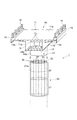
本発明の高架道路1は、図1に示したような鋼製箱桁10を脚柱20に結合することにより構成されるものである。
鋼製箱桁10は、上フランジ11と両ウェブ12と下フランジ13と環状体14とから主要部が構成され、これら主要部の全てが鋼材から形成されている。
上フランジ11は、床版プレート11aの裏側に横リブ11bと縦リブ11cとが設けられたものであり、床版プレート11aの両側方に地覆15と高欄16が固定されている。両ウェブ12は、床版プレート11の裏側に垂直下方に延びるように一体に形成され、その下端に水平方向に下フランジ13が設けられている。環状体14は、下フランジ13の下面に突出するフード14aと、下フランジ13の上面に延長する上方部分14bとを有するものである。また環状体14の上方部分14bの内側には、これよりも小径の鋼管17が下フランジ13上に一体に固定されている。
The elevated road 1 of the present invention is constructed by connecting a
The
The
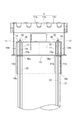
次に、脚柱20はPPRC構造(Precast Prestressed Reinforced Concrete)により形成されるものである。PPRC構造は、プレキャスト鉄筋コンクリートからなる筒状ブロック21を用いる在来構造であり、筒状ブロック21がそれぞれ鉄筋挿通孔(図示せず)とPC鋼棒挿通孔(図示せず)を有し、所定数の筒状ブロック21を積み重ねてPC鋼棒22を挿通孔に挿通し、PC鋼棒22に緊張力を導入して複数の筒状ブロック21を一体化し、PC鋼棒挿通孔にグラウト材(図示せず)を注入する上記工程を繰り返すことにより、全ての筒状ブロック21を積み重ねた後に、鉄筋(図示せず)を挿通孔に挿通してグラウト材(図示せず)を注入して構築されるものである。
在来構造では、PC鋼棒22は筒状ブロック21の上端に定着具により固定されるものであるが、本発明の高架道路1では、図1に示したように、PC鋼棒22が筒状ブロック21の上端よりも上方に突出され、鋼製箱桁10との結合に用いられるものである。
Next, the
In the conventional structure, the
図2は、鋼製箱桁10と脚柱20との結合部の断面図であり、この結合構造では、鋼製箱桁10のフード14aが筒状ブロック21の上端部21aの外周に嵌合され、PC鋼棒22の上端部は下フランジ13に設けられた貫通孔13aに挿通される。そして、PC鋼棒22の上端部は、さらに上方に延長してシース管(図示せず)に通され、環状体14の上方部分14bと小径鋼管17との上に設けられたリング状プレート18に挿通される。筒状ブロック21の上端部21aと下フランジ13との隙間、及び筒状ブロック21の上端部21aと鋼製箱桁10のフード14aとの隙間には、それぞれ無収縮モルタルなどの充填材19a,19bが注入される。また環状体14の上方部分14bと小径鋼管17との間にはコンクリート25が充填される。充填材19a,19bやコンクリート25が充分に硬化したら、PC鋼棒22に緊張力が導入されて定着具26で固定されることにより、鋼製箱桁10と脚柱20との結合構造が構成される。
FIG. 2 is a cross-sectional view of a joint portion between the
以上のように、鋼製箱桁10と脚柱20とが結合され、道路の延長方向に所定数の鋼製箱桁ユニットが連結された後に、床版プレート11a上にアスファルト舗装が施されて高架道路1が構築される。これにより、交差点のような狭い場所における道路の立体化工事を、広い作業帯を占用することなく、急速に施工することが可能なった。また脚柱のPC鋼棒に導入される緊張力により、鋼製箱桁の残留変位を抑制する効果が得られる。さらに、脚柱上端には鋼製箱桁の環状体が嵌合されているので、鋼製箱桁からの力が環状体から脚柱上端に円滑に伝達され、結合部は構造信頼性が高いものになる。
As described above, after the
<実験結果>
次に、本発明の高架構造物を構成するプレストレスト鉄筋コンクリートからなる脚柱と鋼製箱桁との結合部の耐力実験結果を下記に説明する。
実験では、脚柱と鋼製箱桁との結合部を実寸の1/4.5の縮尺で形成し、脚柱側から水平荷重を繰返し加えて変位を測定し、その結果を図3に荷重−変位曲線図として示した。脚柱の保有水平耐力程度までの水平荷重に対しては、鋼製フードとPC鋼棒と鉄筋コンクリート脚柱とが一体として挙動し、脚柱の保有水平耐力を超える荷重を載荷し続けると、鋼製箱桁と脚柱の一体的挙動が困難になり、PC鋼棒への応力集中や、接合部コンクリートの破壊等が生じる。
実験結果から、鋼製箱桁と脚柱上端とがPC鋼棒により緊結されると共に、鋼製箱桁のフードが脚柱上端に嵌合することにより、鋼製箱桁からの力はフードから脚柱上端に円滑に伝達され、鋼製箱桁と脚柱とが一体として挙動することが判った。
<Experimental result>
Next, the test results of the proof stress of the joint between the pedestal made of prestressed reinforced concrete and the steel box girder constituting the elevated structure of the present invention will be described below.
In the experiment, the joint between the pedestal and the steel box girder was formed at a scale of 1 / 4.5 scale, the horizontal load was repeatedly applied from the pedestal side, and the displacement was measured. The result is shown in Fig. 3. It was shown as a curve diagram. For horizontal loads up to the horizontal strength of the pedestal, the steel hood, the PC steel bar, and the reinforced concrete pedestal behave as one body, and if a load exceeding the horizontal strength of the pedestal is continuously loaded, The integral behavior of the box girder and the pedestal becomes difficult, causing stress concentration on the PC steel bar and destruction of the joint concrete.
From the experimental results, the steel box girder and the top of the pedestal column are fastened together with a PC steel rod, and the hood of the steel box girder is fitted to the top of the pedestal column so that the force from the steel box girder is It was found that the steel box girder and the pedestal behaved as a unit, smoothly transmitted to the upper end of the pedestal.
1 高架道路(高架構造物)
10 鋼製箱桁
14a フード(環状体)
20 脚柱
21 筒状ブロック
22 PC鋼棒
26 定着具
1 Elevated road (elevated structure)
10
20
Claims (1)
前記鋼製箱桁の下面に設けられた鋼製環状体が前記脚柱の上端に嵌合され、前記脚柱の上端からはPC鋼棒が上方に突設されて鋼製箱桁の所定箇所に挿通され、当該PC鋼棒の上端が鋼製箱桁に定着具で定着されることにより、PC構造脚柱と鋼製箱桁とが結合されたものである高架構造物。 A plurality of cylindrical precast blocks having insertion holes for reinforcing bars and PC steel bars are stacked, and a prestressed pedestal unit integrally connected by reinforcing bars and PC steel bars respectively inserted into the insertion holes, and a steel box girder And
A steel annular body provided on the lower surface of the steel box girder is fitted to the upper end of the pedestal column, and a PC steel bar protrudes upward from the upper end of the pedestal column, so that a predetermined location of the steel box girder An elevated structure in which the PC structural pedestal and the steel box girder are combined by being inserted into the PC and the upper end of the PC steel bar fixed to the steel box girder with a fixing tool.
Priority Applications (1)
| Application Number | Priority Date | Filing Date | Title |
|---|---|---|---|
| JP2006199170A JP2008025221A (en) | 2006-07-21 | 2006-07-21 | Elevated structure constructed by jointing pier stud of pc structure and steel box girder together |
Applications Claiming Priority (1)
| Application Number | Priority Date | Filing Date | Title |
|---|---|---|---|
| JP2006199170A JP2008025221A (en) | 2006-07-21 | 2006-07-21 | Elevated structure constructed by jointing pier stud of pc structure and steel box girder together |
Publications (1)
| Publication Number | Publication Date |
|---|---|
| JP2008025221A true JP2008025221A (en) | 2008-02-07 |
Family
ID=39116144
Family Applications (1)
| Application Number | Title | Priority Date | Filing Date |
|---|---|---|---|
| JP2006199170A Pending JP2008025221A (en) | 2006-07-21 | 2006-07-21 | Elevated structure constructed by jointing pier stud of pc structure and steel box girder together |
Country Status (1)
| Country | Link |
|---|---|
| JP (1) | JP2008025221A (en) |
Cited By (7)
| Publication number | Priority date | Publication date | Assignee | Title |
|---|---|---|---|---|
| KR101027162B1 (en) | 2010-12-30 | 2011-04-05 | 콘비젼스 주식회사 | Bike bridge using pre-cast concrete panel in river and method for constructing thereof |
| JP2011149202A (en) * | 2010-01-21 | 2011-08-04 | Fletcher Construction Co Ltd | Installation method of bridge pier |
| JP2012082625A (en) * | 2010-10-13 | 2012-04-26 | Hazama Corp | Connecting structure of steel superstructure and concrete column |
| CN103590315B (en) * | 2013-11-25 | 2015-09-02 | 中铁第四勘察设计院集团有限公司 | Public iron is with layer great cantilever steel box-girder |
| CN105672114A (en) * | 2016-01-22 | 2016-06-15 | 中铁大桥勘测设计院集团有限公司 | Opening section top chord and plate-girder combined unit piece provided with same |
| CN109868753A (en) * | 2019-04-18 | 2019-06-11 | 上海市城市建设设计研究总院(集团)有限公司 | Precast assembly pier consolidation structure and its construction method |
| CN112030723A (en) * | 2020-07-31 | 2020-12-04 | 中南大学 | Bridge pier column and pier column joint structure thereof |
-
2006
- 2006-07-21 JP JP2006199170A patent/JP2008025221A/en active Pending
Cited By (9)
| Publication number | Priority date | Publication date | Assignee | Title |
|---|---|---|---|---|
| JP2011149202A (en) * | 2010-01-21 | 2011-08-04 | Fletcher Construction Co Ltd | Installation method of bridge pier |
| JP2012082625A (en) * | 2010-10-13 | 2012-04-26 | Hazama Corp | Connecting structure of steel superstructure and concrete column |
| KR101027162B1 (en) | 2010-12-30 | 2011-04-05 | 콘비젼스 주식회사 | Bike bridge using pre-cast concrete panel in river and method for constructing thereof |
| CN103590315B (en) * | 2013-11-25 | 2015-09-02 | 中铁第四勘察设计院集团有限公司 | Public iron is with layer great cantilever steel box-girder |
| CN105672114A (en) * | 2016-01-22 | 2016-06-15 | 中铁大桥勘测设计院集团有限公司 | Opening section top chord and plate-girder combined unit piece provided with same |
| CN109868753A (en) * | 2019-04-18 | 2019-06-11 | 上海市城市建设设计研究总院(集团)有限公司 | Precast assembly pier consolidation structure and its construction method |
| CN109868753B (en) * | 2019-04-18 | 2024-03-12 | 上海市城市建设设计研究总院(集团)有限公司 | Prefabricated assembled pier beam consolidation structure and construction method thereof |
| CN112030723A (en) * | 2020-07-31 | 2020-12-04 | 中南大学 | Bridge pier column and pier column joint structure thereof |
| CN112030723B (en) * | 2020-07-31 | 2021-11-02 | 湖南省交通规划勘察设计院有限公司 | Bridge pier column and pier column joint structure thereof |
Similar Documents
| Publication | Publication Date | Title |
|---|---|---|
| JP5373979B2 (en) | Construction Method of Steel Composite Girder Bridge {ConstructionMethod SteelCompositeGirderBridge} | |
| WO2006038620A1 (en) | Joined part structure of pedestal and method of joining pedestal | |
| KR101187168B1 (en) | Small river pc bridge and construction method thereof | |
| JP2007077630A (en) | Continuous girder using precast main-girder segment, and its erection method | |
| JP2008025221A (en) | Elevated structure constructed by jointing pier stud of pc structure and steel box girder together | |
| JP2010138643A (en) | Construction method for column-beam joint part of viaduct, and viaduct | |
| JP3844743B2 (en) | Box girder bridge structure and its construction method | |
| JP2015004229A (en) | Pc earthquake-poof joining structure and pc earthquake-proof joining method of column-beam of using steel frame pin | |
| JP2019199710A (en) | Joint structure for precast composite floor slab in direction perpendicular to bridge axis and construction method for same | |
| KR101432087B1 (en) | Composite rahman bridge using preflex beam and horizontal shear connectors and construction method thereof | |
| Mashal et al. | Quasi-static cyclic tests of emulative precast segmental bridge piers (E-PSBP) | |
| JP2010261270A (en) | Composite structure and method for constructing composite structure building | |
| JP2011149265A (en) | Beam member and building structure | |
| JP7028728B2 (en) | Joint structure of foundation pile and foundation slab | |
| JP2006316495A (en) | Foundation structure of bridge pier and its construction method | |
| JP3877995B2 (en) | How to build a string string bridge | |
| JP6918469B2 (en) | Construction method of precast member, erection structure of precast member, erection structure of precast member | |
| JP5423911B2 (en) | Construction method of viaduct column-beam joint, viaduct | |
| Mashal et al. | Quasi-static cyclic testing of half-scale fully precast bridge substructure system in high seismicity | |
| KR102033052B1 (en) | Method for constructing truss bridge support with infilled tube using src girder | |
| CN114045750A (en) | Construction method of high pier column tie beam | |
| JP2006169837A (en) | Column-beam joint structure of reinforced concrete construction | |
| JP5165546B2 (en) | Installation method of bridge support | |
| JP7270412B2 (en) | Reinforcement structure of masonry building | |
| JP6953723B2 (en) | Construction method of seismic isolation structure |