JP2008012612A - Machining method of double-disc machining device - Google Patents
Machining method of double-disc machining device Download PDFInfo
- Publication number
- JP2008012612A JP2008012612A JP2006184841A JP2006184841A JP2008012612A JP 2008012612 A JP2008012612 A JP 2008012612A JP 2006184841 A JP2006184841 A JP 2006184841A JP 2006184841 A JP2006184841 A JP 2006184841A JP 2008012612 A JP2008012612 A JP 2008012612A
- Authority
- JP
- Japan
- Prior art keywords
- roller
- movement amount
- workpiece
- double
- distance data
- Prior art date
- Legal status (The legal status is an assumption and is not a legal conclusion. Google has not performed a legal analysis and makes no representation as to the accuracy of the status listed.)
- Pending
Links
- 238000003754 machining Methods 0.000 title claims abstract description 6
- 238000000034 method Methods 0.000 title claims description 60
- 238000012545 processing Methods 0.000 claims description 103
- 238000012937 correction Methods 0.000 claims description 55
- 238000003672 processing method Methods 0.000 claims description 22
- 230000007246 mechanism Effects 0.000 description 66
- 238000006073 displacement reaction Methods 0.000 description 36
- 230000000452 restraining effect Effects 0.000 description 24
- NJPPVKZQTLUDBO-UHFFFAOYSA-N novaluron Chemical compound C1=C(Cl)C(OC(F)(F)C(OC(F)(F)F)F)=CC=C1NC(=O)NC(=O)C1=C(F)C=CC=C1F NJPPVKZQTLUDBO-UHFFFAOYSA-N 0.000 description 21
- 238000005259 measurement Methods 0.000 description 20
- 239000011159 matrix material Substances 0.000 description 10
- 238000010586 diagram Methods 0.000 description 9
- 238000012935 Averaging Methods 0.000 description 7
- 230000002093 peripheral effect Effects 0.000 description 7
- 238000005096 rolling process Methods 0.000 description 6
- 239000006185 dispersion Substances 0.000 description 3
- 230000000694 effects Effects 0.000 description 3
- XUIMIQQOPSSXEZ-UHFFFAOYSA-N Silicon Chemical compound [Si] XUIMIQQOPSSXEZ-UHFFFAOYSA-N 0.000 description 1
- 238000011156 evaluation Methods 0.000 description 1
- 239000004744 fabric Substances 0.000 description 1
- 239000011521 glass Substances 0.000 description 1
- 239000000463 material Substances 0.000 description 1
- 238000012986 modification Methods 0.000 description 1
- 230000004048 modification Effects 0.000 description 1
- 238000005498 polishing Methods 0.000 description 1
- 229910052710 silicon Inorganic materials 0.000 description 1
- 239000010703 silicon Substances 0.000 description 1
- 230000001629 suppression Effects 0.000 description 1
Images




Landscapes
- Constituent Portions Of Griding Lathes, Driving, Sensing And Control (AREA)
- Grinding Of Cylindrical And Plane Surfaces (AREA)
Abstract
Description
本発明は、特にワーク保持装置により保持されたガラスやシリコン等の硬脆性材料よりなるワークの両面を加工する両面加工装置の加工方法に関する。 The present invention particularly relates to a processing method of a double-sided processing apparatus that processes both surfaces of a work made of a hard and brittle material such as glass or silicon held by a work holding apparatus.
ワーク保持装置に保持されたワークの両面を高精度に加工可能な従来の両面加工装置として、例えば、図1に示すような両面加工装置200がある。
As a conventional double-side processing apparatus capable of processing both surfaces of a work held by a work holding apparatus with high accuracy, for example, there is a double-
図1は、従来の両面加工装置の概略構成図である。図1において、X,X方向は研削主軸205,211の移動方向、Y,Y方向はX,X方向と直交する方向をそれぞれ示している。
FIG. 1 is a schematic configuration diagram of a conventional double-side processing apparatus. In FIG. 1, the X and X directions indicate the movement directions of the
図1を参照するに、従来の両面加工装置200は、第1の加工装置201と、第2の加工装置202と、ワーク保持装置203とを有する。
Referring to FIG. 1, a conventional double-
第1の加工装置201は、ワーク保持装置203に保持されたワーク215の面215Aと対向するように配置されている。第1の加工装置201は、研削主軸205と、台座206と、砥石207とを有する。研削主軸205は、X,X方向に移動可能であると共に、回転可能な構成とされている。台座206は、ワーク保持装置203側に位置する研削主軸205の端部に設けられている。砥石207は、台座206に取り付けられている。砥石207は、ワーク215の面215Aと接触する研削動作面207Aを有する。砥石207は、研削主軸205が回転移動した際、研削主軸205と一体的に回転移動する。第1の加工装置201は、回転移動する砥石207の研削動作面207Aにより、ワーク215の面215Aを加工する。
The
第2の加工装置202は、ワーク215を介して、第1の加工装置201と対向するように配置されている。第2の加工装置202は、研削主軸211と、台座212と、砥石213とを有する。研削主軸211は、X,X方向に移動可能であると共に、回転可能な構成とされている。台座212は、ワーク保持装置203側に位置する研削主軸211の端部に設けられている。砥石213は、台座212に取り付けられている。砥石213は、ワーク215の面215Bと接触する研削動作面213Aを有する。砥石213は、研削主軸211が回転移動した際、研削主軸211と一体的に回転移動する。第2の加工装置202は、回転移動する砥石213の研削動作面213Aにより、ワーク215の面215Bを加工する。
The
ワーク保持装置203は、フレーム217と、手動ローラ位置調整機構221〜223と、溝付きローラ225〜227とを有する。フレーム217は、複数のネジ穴(図示せず)を有する。手動ローラ位置調整機構221〜223は、ネジ部221A〜223Aを有する。ネジ部221A〜223Aは、フレーム217に形成されたネジ穴(図示せず)と締結されている。手動ローラ位置調整機構221〜223は、溝付きローラ225〜227の軸方向の位置を作業者が手動で調整するためのものである。
The
溝付きローラ225は、ワーク215の外周部と接触する溝225Aを有する。溝付きローラ225は、回転可能な状態で手動ローラ位置調整機構221に設けられている。溝付きローラ226は、ワーク215の外周部と接触する溝226Aを有する。溝付きローラ226は、回転可能な状態で手動ローラ位置調整機構222に設けられている。溝付きローラ227は、ワーク215の外周部と接触する溝227Aを有する。溝付きローラ227は、回転可能な状態で手動ローラ位置調整機構223に設けられている。ワーク215は、溝付きローラ225〜227の溝225A〜227Aにより回転可能に保持されている。
The
溝付きローラ225〜227の軸方向の位置調整は、ワーク215を加工する前に、作業者が手動ローラ位置調整機構221〜223を手動で回転させることで行う。このとき、溝付きローラ225〜227の溝225A〜227Aにより形成されるローラ拘束面Aと、回転する砥石207の研削動作面207Aにより形成される回転軌跡面B(図示せず)とが略平行となるように、溝付きローラ225〜127の軸方向における位置の調整を行う。
The position adjustment of the
このように、ローラ拘束面Aと回転軌跡面Bとが略平行となるように、溝付きローラ225〜127の溝225A〜227Aの位置を調整し、その後、ワーク215を加工することにより、ワーク215の両面215A,215Bを高精度(具体的には、ワーク215の両面215A,215Bの平坦度の向上やナノトポグラフィの抑制等)に加工することができる。
Thus, by adjusting the positions of the
なお、ローラ拘束面Aと回転軌跡面Bとが略平行となったかどうかのチェックは、台座206又は研削主軸205にセンサー(図示せず)を取り付けて行う。また、センサー(図示せず)は、溝付きローラ225〜227の位置調整後に台座206又は研削主軸205から取り外す(例えば、特許文献1参照。)。
しかしながら、従来の両面加工装置200では、溝付きローラ225〜227の位置調整を作業者が手動で行っていたため、ローラ拘束面Aと回転軌跡面Bとが略平行となるように溝付きローラ225〜227の位置を調整することは非常に困難であった。そのため、ワーク215の両面215A,215Bを高精度に加工することができないという問題があった。
However, in the conventional double-
そこで、本発明は上記の点に鑑みてなされたものであり、ワークを保持する溝付きローラの位置調整を容易に行うことができると共に、ワークの両面を高精度に加工することのできる両面加工装置の加工方法を提供することを目的とする。 Accordingly, the present invention has been made in view of the above points, and can perform the position adjustment of the grooved roller for holding the workpiece easily, and can perform both sides of the workpiece with high accuracy. It aims at providing the processing method of an apparatus.
本発明の一観点によれば、複数の溝付きローラに形成された溝により前記ワークを回転可能に保持するワーク保持装置と、前記ワーク保持装置を介して、対向するように配置された第1及び第2の加工部材と、を備え、前記第1及び第2の加工部材により、前記ワークの第1の面及び第2の面を加工する両面加工装置の加工方法であって、前記ワークの前記第1の面の第1の所定位置からセンサまでの第1の距離に関する第1の距離データ、及び/又は前記ワークの前記第2の面の第2の所定位置から前記センサまでの第2の距離に関する第2の距離データを取得する距離データ取得工程と、前記複数の溝付きローラの前記溝により形成されるローラ拘束面が所定の面となるように、前記第1の距離データ及び/又は前記第2の距離データに基づいて、前記複数の溝付きローラの軸方向の移動量を求める移動量演算工程と、前記移動量に基づいて、前記複数の溝付きローラの前記軸方向の位置を自動調整するローラ位置自動調整工程と、を含むことを特徴とする両面加工装置の加工方法が提供される。 According to one aspect of the present invention, a workpiece holding device that rotatably holds the workpiece by grooves formed in a plurality of grooved rollers, and a first arranged to face each other via the workpiece holding device. And a second processing member, and a processing method of a double-side processing apparatus that processes the first surface and the second surface of the workpiece by the first and second processing members, First distance data related to a first distance from the first predetermined position on the first surface to the sensor and / or a second distance from the second predetermined position on the second surface of the workpiece to the sensor. A second distance data acquisition step for acquiring second distance data relating to the distance of the first distance data, and the first distance data and / or the roller constraint surface formed by the grooves of the plurality of grooved rollers to be a predetermined surface. Or the second distance data Accordingly, a movement amount calculating step for obtaining movement amounts in the axial direction of the plurality of grooved rollers, and automatic roller position adjustment for automatically adjusting the axial positions of the plurality of grooved rollers based on the movement amounts. And a processing method for a double-sided processing apparatus.
本発明によれば、複数の溝付きローラの溝により形成されるローラ拘束面が所定の面となるように、第1の距離データ及び/又は第2の距離データに基づいて、複数の溝付きローラの軸方向の移動量を求め、この移動量に基づいて、複数の溝付きローラの軸方向の位置を自動調整することにより、ワークを保持する溝付きローラの位置調整を容易に行うことができる。また、ローラ拘束面が所定の面となるように複数の溝付きローラの軸方向の位置を自動調整後にワークの加工を行うことにより、ワークの両面を高精度に加工することができる。 According to the present invention, a plurality of grooves are provided on the basis of the first distance data and / or the second distance data so that the roller constraining surface formed by the grooves of the plurality of grooved rollers is a predetermined surface. By determining the amount of movement of the roller in the axial direction and automatically adjusting the position of the plurality of grooved rollers in the axial direction based on this amount of movement, the position of the grooved roller that holds the workpiece can be easily adjusted. it can. Further, by processing the workpiece after automatically adjusting the axial positions of the plurality of grooved rollers so that the roller constraining surface becomes a predetermined surface, both surfaces of the workpiece can be processed with high accuracy.
本発明は、溝付きローラの位置調整を容易に行うことができると共に、ワークの両面を高精度に加工することができる。 The present invention can easily adjust the position of the grooved roller and can process both surfaces of the workpiece with high accuracy.
次に、図面に基づいて本発明の実施の形態を説明する。 Next, embodiments of the present invention will be described with reference to the drawings.
(実施の形態)
図2は、本発明の実施の形態に係る両面加工装置の概略構成図である。図2において、X,X方向はサドル22,32の移動方向、Y,Y方向はX,X方向と直交する方向をそれぞれ示している。
(Embodiment)
FIG. 2 is a schematic configuration diagram of the double-sided processing apparatus according to the embodiment of the present invention. In FIG. 2, the X and X directions indicate the movement directions of the
図2を参照するに、第1の実施の形態の両面加工装置10は、両面加工装置本体11と、移動量演算手段12と、制御手段13とを有する。
Referring to FIG. 2, the double-
両面加工装置本体11は、架台15と、第1の加工装置16と、第2の加工装置17と、ワーク保持装置18と、測定装置19とを有する。架台15は、板部15Aと、突出部15B,15Cとを有する。架台15は、第1及び第2の加工装置16,17と、ワーク保持装置18とを支持するためのものである。
The double-sided processing device main body 11 includes a
第1の加工装置16は、サドル移動装置21と、サドル22と、研削主軸23と、第1の回転駆動装置(図示せず)と、台座24と、第1の加工部材である砥石25とを有する。
The
サドル移動装置21は、架台15の突出部15B上に設けられている。サドル移動装置21は、サドル22をX,X方向に移動させるためのものである。サドル22は、突出部15Bとワーク保持装置18との間に位置する架台15の板部15A上に設けられている。サドル22は、サドル移動装置21と接続されている。サドル22は、X,X方向に移動可能な状態で架台15に支持されている。
The
研削主軸23は、サドル移動装置21が接続された側とは反対側に位置するサドル22に設けられている。研削主軸23は、サドル移動装置21によりサドル22がX,X方向に移動させられた際、サドル22と一体的に移動する。第1の回転駆動装置(図示せず)は、研削主軸23を回転させるためのものである。
The grinding
台座24は、ワーク保持装置18側に位置する研削主軸23に設けられている。台座24は、円環状の突出部24Aと、ネジ穴24Bとを有する。ネジ穴24Bは、台座24に測定装置19を装着するためのものである。台座24は、研削主軸23が回転移動した際、研削主軸23と一体的に回転移動する。
The
砥石25は、円環状とされており、台座24の突出部24Aに設けられている。砥石25は、台座24が回転移動させられた際、台座24と一体的に回転移動する。砥石25は、ワーク27の第1の面27Aと接触する研削動作面25Aを有する。研削動作面25Aは、ワーク27の中心位置を通過するように配置されている。
The
上記構成とされた第1の加工装置16は、回転移動する砥石25の研削動作面25Aにより、ワーク27の第1の面27A側を加工する。
The
第2の加工装置17は、サドル移動装置31と、サドル32と、研削主軸33と、第2の回転駆動装置(図示せず)と、台座34と、第2の加工部材である砥石35とを有する。
The
サドル移動装置31は、架台15の突出部15C上に設けられている。サドル移動装置31は、サドル32をX,X方向に移動させるためのものである。サドル32は、突出部15Cとワーク保持装置18との間に位置する架台15の板部15A上に設けられている。サドル32は、X,X方向に移動可能な状態で架台15に支持されている。サドル32は、サドル移動装置31と接続されている。
The
研削主軸33は、サドル移動装置31が接続された側とは反対側に位置するサドル32に設けられている。研削主軸33は、サドル移動装置31によりサドル32がX,X方向に移動させられた際、サドル32と一体的に移動する。第2の回転駆動装置(図示せず)は、研削主軸33を回転させるためのものである。
The grinding
台座34は、ワーク保持装置18側に位置する研削主軸33に設けられている。台座34は、円環状の突出部34Aを有する。台座34は、研削主軸33が回転移動させられた際、研削主軸33と一体的に回転移動する。
The
砥石35は、円環状とされており、台座34の突出部34Aに設けられている。砥石35は、台座34が回転移動させられた際、台座34と一体的に回転移動する。砥石35は、ワーク27の第2の面27Bと接触する研削動作面35Aを有する。研削動作面35Aは、ワーク27の中心位置を通過するように配置されている。
The
上記構成とされた第2の加工装置17は、回転移動する砥石35の研削動作面35Aにより、ワーク27の第2の面27B側を加工する。
The
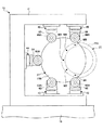
図3は、図2に示すワーク保持装置をD視した図である。 3 is a view of the work holding device shown in FIG.
図3を参照するに、ワーク保持装置18は、フレーム41と、ローラ位置自動調整機構42〜46と、ローラ支持機構52〜56と、溝付きローラ62〜66とを有する。
Referring to FIG. 3, the
フレーム41は、第1の加工装置16と第2の加工装置17との間に位置する架台15の板部15A上に設けられており、コの字型とされている。
The
ローラ位置自動調整機構42,43は、フレーム41の下部内壁41Aに設けられている。ローラ位置自動調整機構44は、フレーム41の内壁41Bに設けられている。ローラ位置自動調整機構45,46は、フレーム41の上部内壁41Cに設けられている。ローラ位置自動調整機構42〜46は、ローラ支持機構52〜56を介して、溝付きローラ62〜66の軸方向に溝付きローラ62〜66を移動させて、溝付きローラ62〜66の溝62A〜66Aの位置を自動で調整するためのものである(図2参照)。
The roller position
このように、溝付きローラ62〜66の溝62A〜66Aの軸方向の位置を自動調整するローラ位置自動調整機構42〜46を設けることにより、作業者が溝付きローラ62〜66の軸方向の位置調整を手動で行なった場合と比較して、容易に溝付きローラ62〜66の溝62A〜66Aの位置の調整を行うことができる。
As described above, by providing the roller position
図4は、図3に示すローラ位置自動調整機構のE−E線方向の断面図であり、図5は、図4に示すローラ位置自動調整機構のH−H線方向の断面図である。 4 is a cross-sectional view of the roller position automatic adjustment mechanism shown in FIG. 3 in the EE line direction, and FIG. 5 is a cross-sectional view of the roller position automatic adjustment mechanism shown in FIG. 4 in the HH line direction.
図4及び図5を参照して、ローラ位置自動調整機構42の具体的な構成について説明する。ローラ位置自動調整機構42は、回転モータ71と、ボールネジ72と、ガイドベース73と、複数のボールネジ軸受74と、支持体75と、ステージ77と、転がりガイド78とを有する。
A specific configuration of the roller position
回転モータ71は、フレーム41上に設けられている。回転モータ71は、制御手段13と電気的に接続されている。回転モータ71は、制御手段13の指令に基づいて、ボールネジ72を回転させて、支持体75を溝付きローラ62の軸方向に移動させるためのものである。
The
ボールネジ72は、その長手方向が溝付きローラ62の軸方向となるように回転モータ71と接続されている。ボールネジ72は、ガイドベース73に形成された貫通穴73Bを貫通すると共に、ガイドベース73の収容部73Aに延在するように配置されている。
The ball screw 72 is connected to the
ガイドベース73は、フレーム41に設けられている。ガイドベース73は、収容部73Aと、貫通穴73Bと、一対の突出部81,82とを有する。収容部73Aは、ボールネジ72の一部及び支持体75を収容するためのものである。貫通穴73Bは、回転モータ71と対向するガイドベース73部分に形成されている。一対の突出部81,82は、ボールネジ72を介して対向するように配置されている。
The
複数のボールネジ軸受74は、貫通穴73Bに対応するガイドベース73に設けられている。複数のボールネジ軸受74は、ボールネジ72を回転可能に支持している。
The plurality of ball screw
支持体75は、収容部73Aに収容されたボールネジ72に設けられている。支持体75は、溝付きローラ62を支持するローラ支持機構52を配設するためのものである。支持体75は、ボールネジ72が回転した際、溝付きローラ62の軸方向に移動する。これにより、ローラ支持機構52が溝付きローラ62の軸方向に移動するので、溝付きローラ62の溝62Aの位置調整を自動で行うことができる。
The
ステージ77は、板部84と、突出部85,86とを有する。板部84は、支持体75上に固定されている。板部84は、収容部73Aの上面を覆うように配置されている。突出部85,86は、板部84に設けられている。突出部85は、ガイドベース73の突出部81と対向するように配置されている。突出部86は、ガイドベース73の突出部82と対向するように配置されている。ステージ77は、ローラ支持機構52を配設するためのものである。
The
転がりガイド78は、第1のガイド板91,92と、第2のガイド板93,94と、複数のボール95,96とを有する。第1のガイド板91は、突出部81の外壁81Aに設けられている。第1のガイド板91には、複数のボール95の一部を収容する溝が形成されている。第1のガイド板92は、突出部82の外壁82Aに設けられている。第1のガイド板92には、複数のボール96の一部を収容する溝が形成されている。
The rolling
第2のガイド板93は、突出部85の内壁85Aに設けられている。第2のガイド板93には、複数のボール95の一部を収容する溝が形成されている。第2のガイド板94は、突出部86の内壁86Aに設けられている。第2のガイド板94には、複数のボール96の一部を収容する溝が形成されている。
The
複数のボール95は、第1及び第2のガイド板91,93に形成された溝に収容されている。複数のボール96は、第1及び第2のガイド板92,94に形成された溝に収容されている。
The plurality of
上記構成とされた転がりガイド78は、複数のボール95,96が第1及び第2のガイド板91,92,93,94に形成された溝を移動することで、溝付きローラ62の軸方向にステージ77を案内するためのガイドである。
The rolling
ローラ位置自動調整機構43〜46は、上記説明したローラ位置自動調整機構42と同様な構成とされている。
The roller position
なお、回転モータ71及びボールネジ72からなるローラ位置自動調整機構42〜46のアクチュエータのストロークは第1及び第2のガイド板91〜94に形成された溝の加工精度の約10倍程度あればよい。また、上記アクチュエータの位置決め精度としては、所望の調整精度の1/10程度であればよい。
In addition, the stroke of the actuator of the roller position
図4を参照するに、ローラ支持機構52は、回転軸収容部材98と、ローラ用回転軸99と、複数の軸受101とを有する。回転軸収容部材98は、ステージ77上に設けられている。回転軸収容部材98は、ローラ用回転軸99を挿入するための貫通部98Aを有する。ローラ用回転軸99は、貫通部98Aを貫通すると共に、回転軸収容部材98から突出するように配置されている。ローラ用回転軸99は、溝付きローラ62を配設するためのものである。
Referring to FIG. 4, the
複数の軸受101は、貫通部98Aを形成する回転軸収容部材98に設けられている。複数の軸受101は、ローラ用回転軸99を回転可能に支持するためのものである。
The plurality of
ローラ支持機構53〜56は、上記説明したローラ支持機構52と同様な構成とされている。また、ローラ支持機構53は、ローラ位置自動調整機構43に設けられており、ローラ支持機構54は、ローラ位置自動調整機構44に設けられている(図3参照)。また、ローラ支持機構55は、ローラ位置自動調整機構45に設けられており、ローラ支持機構56は、ローラ位置自動調整機構46に設けられている(図3参照)。
The
図4を参照するに、溝付きローラ62は、ローラ支持機構52に設けられたローラ用回転軸99に配設されている。溝付きローラ62は、ワーク27の外周部と接触する溝62Aを有する。溝付きローラ62は、ローラ支持機構52が溝付きローラ62の軸方向(ローラ支持機構52に設けられたローラ用回転軸99の軸方向)に移動させられた際、ローラ支持機構52と一体的に移動する。
Referring to FIG. 4, the
次に、図3を参照して、溝付きローラ63〜66について説明する。溝付きローラ63は、ローラ支持機構53に設けられたローラ用回転軸99に配設されている。溝付きローラ63は、ワーク27の外周部と接触する溝63Aを有する。溝付きローラ63は、ローラ支持機構53が溝付きローラ63の軸方向に移動させられた際、ローラ支持機構53と一体的に移動する。
Next, the
溝付きローラ64は、ローラ支持機構54に設けられたローラ用回転軸99に配設されている。溝付きローラ64は、ワーク27の外周部と接触する溝64Aを有する。溝付きローラ64は、ローラ支持機構54が溝付きローラ64の軸方向に移動させられた際、ローラ支持機構54と一体的に移動する。
The
溝付きローラ65は、ローラ支持機構55に設けられたローラ用回転軸99に配設されている。溝付きローラ65は、ワーク27の外周部と接触する溝65Aを有する。溝付きローラ65は、ローラ支持機構55が溝付きローラ65の軸方向に移動した際、ローラ支持機構55と一体的に移動する。
The
溝付きローラ66は、ローラ支持機構56に設けられたローラ用回転軸99に配設されている。溝付きローラ66は、ワーク27の外周部と接触する溝66Aを有する。溝付きローラ66は、ローラ支持機構56が溝付きローラ66の軸方向に移動した際、ローラ支持機構56と一体的に移動する。
The
溝付きローラ65,66は、ワーク27を加工する際、図示していない駆動装置により回転させられる。このとき、溝付きローラ62〜64は、溝付きローラ65,66により回転させられるワーク27の回転運動により、従動回転する。
The
図2を参照するに、測定装置19は、支持部材103と、ネジ部104と、センサ105とを有する。支持部材103は、L字形状とされている。支持部材103は、センサ105を配設するためのものである。ネジ部104は、支持部材103の一方の端部に設けられている。ネジ部104は、台座24に形成されたネジ穴24Bと締結されている。これにより、台座24に支持部材103が固定される。
Referring to FIG. 2, the
図6は、砥石とセンサとの位置関係を説明するための図である。 FIG. 6 is a diagram for explaining the positional relationship between the grindstone and the sensor.
図6を参照するに、センサ105は、研削動作面25Aと対向する部分の支持部材103に設けられている。センサ105は、センサ105からワーク27の第1の面27Aの第1の所定位置及び/又はワーク27の第2の面27Bの第2の所定位置までの第1の距離及び/又は第2の距離を測定して、第1の距離データ及び/又は第2の距離データを取得するためのものである。なお、本実施の形態では、センサ105により第1の距離データと第2の距離データの両方を取得する場合を例に挙げて以下の説明を行う。
Referring to FIG. 6, the
図7は、センサが測定する第1の所定位置の一例を示す図である。図7において、F1〜F5はワーク27の第1の面27Aの第1の所定位置(以下、「第1の所定位置F1〜F5」とする)を示している。
FIG. 7 is a diagram illustrating an example of a first predetermined position measured by the sensor. In FIG. 7, F <b> 1 to F <b> 5 indicate first predetermined positions (hereinafter referred to as “first predetermined positions F <b> 1 to F <b> 5”) of the
図7を参照して、ワーク27の第1の面27Aの第1の所定位置F1〜F5について説明する。第1の所定位置F1〜F5は、砥石25の研削動作面25Aと対向する領域のワーク27の第1の面27A内に適宜設定することができる。例えば、図7に示すように、第1の所定位置F1を溝付きローラ62の近傍に配置し、第1の所定位置F2を溝付きローラ63の近傍に配置し、第1の所定位置F3を溝付きローラ64の近傍に配置し、第1の所定位置F4を溝付きローラ65の近傍に配置し、第1の所定位置F5を溝付きローラ66の近傍に配置するとよい。
With reference to FIG. 7, the first predetermined positions F1 to F5 of the
このように、第1の所定位置F1〜F5を溝付きローラ62〜66の近傍に配置することにより、センサ105から第1の所定位置F1〜F5までの第1の距離を測定した際に取得される第1の距離データに溝付きローラ62〜66の軸方向の位置に関するデータを多く含ませることができる。
As described above, the first predetermined positions F1 to F5 are arranged in the vicinity of the
なお、図7では、第1の所定位置の数(この場合5つ)と溝付きローラ62〜66の数(この場合5つ)とが等しい場合を例に挙げたが、第1の所定位置の数を溝付きローラ62〜66の数よりも多く設定してもよい。第1の所定位置の数は、溝付きローラ62〜66の数と等しいか、或いは溝付きローラ62〜66の数よりも多ければよい。
In FIG. 7, the case where the number of the first predetermined positions (in this case, five) and the number of the
図8は、センサが測定する第2の所定位置の一例を示す図である。図8において、M1〜M5はワーク27の第2の面27Bの第2の所定位置(以下、「第2の所定位置M1〜M5」とする)を示している。
FIG. 8 is a diagram illustrating an example of a second predetermined position measured by the sensor. 8, M1 to M5 indicate second predetermined positions (hereinafter referred to as “second predetermined positions M1 to M5”) of the
図8を参照して、ワーク27の第2の面27Aの第2の所定位置M1〜M5について説明する。第2の所定位置M1〜M5は、砥石25の研削動作面25Aと対向する領域のワーク27の第2の面27B内に適宜設定することができる。例えば、図8に示すように、第2の所定位置M1を溝付きローラ62の近傍に設定し、第2の所定位置M2を溝付きローラ63の近傍に配置し、第2の所定位置M3を溝付きローラ64の近傍に配置し、第2の所定位置M4を溝付きローラ65の近傍に配置し、第2の所定位置M5を溝付きローラ66の近傍に配置するとよい。
The second predetermined positions M1 to M5 of the
このように、第2の所定位置M1〜M5を溝付きローラ62〜66の近傍に配置することにより、センサ105から第2の所定位置M1〜M5までの第1の距離を測定した際に取得される第1の距離データに溝付きローラ62〜66の軸方向の位置に関するデータを多く含ませることができる。
As described above, the second predetermined positions M1 to M5 are arranged in the vicinity of the
なお、センサ105により第2の所定位置M1〜M5からセンサ105までの第2の距離を測定する場合には、図7に示すワーク27の状態(研削動作面25Aとワーク27の第1の面27Aとが対向する状態)から、図8に示すように、研削動作面25Aとワーク27の第2の面27Bが対向するようにワーク27を反転させる。
When measuring the second distance from the second predetermined positions M1 to M5 to the
また、図8では、第2の所定位置の数(この場合5つ)と溝付きローラ62〜66の数(この場合5つ)とが等しい場合を例に挙げたが、第2の所定位置の数を溝付きローラ62〜66の数よりも多く設定してもよい。第2の所定位置の数は、溝付きローラ62〜66の数と等しいか、或いは溝付きローラ62〜66の数よりも多ければよい。また、第2の所定位置の数は、第1の所定位置の数と等しくするとよい。
FIG. 8 shows an example in which the number of second predetermined positions (in this case, five) is equal to the number of
ここで、第1及び第2の所定位置F1〜F5,M1〜M5をセンサ105が測定する場合(第1の所定位置F1〜F5の数と第2の所定位置M1〜M5の数と溝付きローラ62〜66の数とが等しい場合)を例に挙げて、センサ105が予め取得するローラ変位量データFA,FBについて説明する。
Here, when the
センサ105は、ワーク保持装置18によりワーク27を回転させた状態で、溝付きローラ62〜66を軸方向に変位させない状態(初期状態)で、センサ105から第1の所定位置F1〜F5までの距離を測定して、初期状態の距離データを取得する。
The
センサ105は、ワーク保持装置18によりワーク27を回転させた状態で、溝付きローラ62のみを溝付きローラ62の軸方向に所定の変位量gだけ変位させたときのセンサ105から第1の所定位置F1〜F5までの距離を測定する。続いて、溝付きローラ63のみを溝付きローラ63の軸方向に所定の変位量gだけ変位させたときのセンサ105から第1の所定位置F1〜F5までの距離を測定する。次いで、溝付きローラ64のみを溝付きローラ64の軸方向に所定の変位量gだけ変位させたときのセンサ105から第1の所定位置F1〜F5までの距離を測定する。続いて、溝付きローラ65のみを溝付きローラ65の軸方向に所定の変位量gだけ変位させたときのセンサ105から第1の所定位置F1〜F5までの距離を測定する。次いで、溝付きローラ66のみを溝付きローラ66の軸方向に所定の変位量gだけ変位させたときのセンサ105から第1の所定位置F1〜F5までの距離を測定する。
The
ローラ変位量データFAは、各溝付きローラ62〜66を個別に変位させたときの上記距離に関するデータから初期状態の距離データを引くことにより求められるデータである。この場合のローラ変位量データFAは、5×5の行列で表されるデータである。
Roller displacement amount data F A is data obtained by subtracting the distance data of the initial state from the data relating to the distance when each of the
ローラ変位量データFBは、センサ105とワーク27の第2の面27Bが対向するようにワーク27を反転させ(図8に示す状態)、その後、ローラ変位量データFAを取得するときと同様な手法により取得する。この場合のローラ変位量データFBは、5×5の行列で表されるデータである。センサ105により取得されたローラ変位量データFA,FBは、移動量演算手段12に送信され、記憶部12Aに記憶される。
Roller displacement amount data F B inverts the
また、上記所定の変位量gは、センサ105の計測精度よりも十分に大きな値であればよい。所定の変位量gは、例えば、10μm〜100μmの範囲内で設定することができる。
The predetermined displacement g may be a value sufficiently larger than the measurement accuracy of the
なお、上記5回の測定を複数行って、平均化したデータに基づいてローラ変位量データFA,FBを求めてもよい。 It should be noted that a plurality of the above five measurements may be performed to obtain the roller displacement amount data F A and F B based on the averaged data.
このように、上記5回の測定を複数行って複数のローラ変位量データを取得し、この複数のローラ変位量データを平均化してローラ変位量データFA,FBを取得することにより、ローラ変位量データFA,FBに含まれる計測誤差成分(例えば、センサ105の測定誤差等)を低減させることができる。 In this way, a plurality of the above five measurements are performed to obtain a plurality of roller displacement amount data, and the plurality of roller displacement amount data are averaged to obtain the roller displacement amount data F A and F B. A measurement error component (for example, a measurement error of the sensor 105) included in the displacement amount data F A and F B can be reduced.
また、センサ105は、ワーク保持装置18によりワーク27を回転させると共に、全ての溝付きローラ62〜66を変位させない状態で、センサ105から第1の所定位置F1〜F5までの第1の距離を順次測定して、第1の距離データd1−1〜d1−5を取得すると共に、センサ105から第2の所定位置M1〜M5までの第2の距離を順次測定して、第2の距離データd2−1〜d2−5を取得する。第1の距離データd1−1〜d1−5及び第2の距離データd2−1〜d2−5は、複数の溝付きローラ62〜66の溝62A〜66Aにより形成されるローラ拘束面J(図2参照)の形状に対応したローラ拘束面形状データJdを取得する際に用いられるデータである。
In addition, the
センサ105は、移動量演算手段12と電気的に接続されている。センサ105により取得された第1の距離データd1−1〜d1−5及び第2の距離データd2−1〜d2−5は、移動量演算手段12に送信される。
The
このように、台座24に取り付けられ、センサ105を所定の位置に移動させる駆動部を備えていない測定装置19を用いることにより、センサ105が取得するローラ変位量データFA,FB、第1の距離データd1−1〜d1−5、及び第2の距離データd2−1〜d2−5に含まれる運動誤差成分を小さくすることができる。
In this way, by using the measuring
図2を参照するに、移動量演算手段12は、記憶部12Aと、補正部12Bと、演算部12Cとを有する。記憶部12Aには、ローラ変位量データFA,FB、ワーク27の所定の形状に関するデータTw、ローラ拘束面Jの所定の形状に関するデータTJ等が記憶されている。ワーク27の所定の形状に関するデータTwとは、例えば、ワーク27の厚さに関するスペックや、ワークの反りやナノトポグラフィに関するスペック等に関するデータである。ワーク27の所定の形状に関するデータTwは、両面加工装置10によりワーク27を加工するか否かを判断する際に使用されるデータである。
Referring to FIG. 2, the movement amount calculation means 12 includes a
ローラ拘束面Jの所定の形状に関するデータTJとは、例えば、センサ105からワーク27の第1の面27Aまでの距離を複数測定したときの最大値から最小値を引いた値のスペックに関するデータである。ローラ拘束面Jの所定の形状に関するデータTJは、両面加工装置10によりワーク27を加工するか否かを判定する際に使用されるデータである。
The data T J for a given shape of the roller restraint surface J, for example, data relating to the value of specifications by subtracting the minimum value from the maximum value when the sensor 105 a plurality measure the distance to the
補正部12Bは、第1の距離データd1−1〜d1−5及び第2の距離データd2−1〜d2−5のそれぞれに対して平均化処理やローパスフィルタ処理を行う。
The
これにより、第1の距離データd1−1〜d1−5からワーク27の振動や溝付きローラ62〜66の振れ成分等が低減された中心値データd1−1A〜d1−5Aが取得され、第2の距離データd2−1〜d2−5からワーク27の振動や溝付きローラ62〜66の振れ成分等が低減された中心値データd2−1A〜d2−5Aが取得される。
As a result, the center value data d1-1A to d1-5A in which the vibration of the
上記中心値データd1−1A〜d1−5A,d2−1A〜d2−5Aは、補正部12Bから演算部12Cに送信される。中心値データd1−1A〜d1−5A,d2−1A〜d2−5Aは、ローラ拘束面形状データJdを求める際に使用される。
The center value data d1-1A to d1-5A and d2-1A to d2-5A are transmitted from the
このように、ワーク27の振動や溝付きローラ62〜66の振れ成分等が除去された中心値データd1−1A〜d1−5A,d2−1A〜d2−5Aに基づいて、ローラ拘束面形状データJdを求めることにより、ローラ拘束面形状データJdに含まれるワーク27に関する運動誤差成分や溝付きローラ62〜66に関する運動誤差成分等を低減することができる。
Thus, based on the center value data d1-1A to d1-5A and d2-1A to d2-5A from which the vibration of the
また、補正部12Bは、演算部12Cにより求められる移動量G2(移動量推定値)に基づいて、ローラ位置自動調整機構42〜46が溝付きローラ62〜66の軸方向の位置を調整後に、センサ105が測定することにより取得されるワーク拘束面JがデータTJを満たしているか否かの判定を行う。ワーク拘束面JがデータTJを満たしていないと判定された場合(ローラ拘束面形状データJdに重畳している誤差成分を十分に低減できていない場合)、補正部12Bは、移動量G2に補正係数KC(<1)を掛けて、移動量G2を補正して移動量G3(=G2・KC)を算出する。補正係数KCは、所定の値を有する補正係数である。
Further, the correcting
このようにして求められる移動量G3(移動量推定値)に基づいて、溝付きローラ62〜66の軸方向の位置を調整することにより、調整後のローラ拘束面Jの形状がデータTJを満たすことができる。
By adjusting the axial positions of the
ところで、ローラ拘束面Jの形状がデータTJを満たすような移動量G3を取得するためには、センサ105による計測と補正部12Bによる補正とを繰り返し行う必要があるため、多くの時間を要する。そこで、予め第1及び第2の距離データd1−1〜d1−5,d2−1〜d2−5の繰り返し計測精度の標準偏差σ1を求めておき、移動量G2が標準偏差σ1よりもかなり大きい場合には、補正係数KCHを1(KCH=1)とし、移動量G2(移動量推定値)が繰り返し計測精度の標準偏差σ1よりもそれほど大きくない場合には、補正係数KCH(KCH<1)をローラ拘束面形状データJdに応じて可変させて、移動量G2の補正を行う可変フィードバック処理を適用するとよい。
By the way, in order to acquire the movement amount G3 so that the shape of the roller constraining surface J satisfies the data TJ , it is necessary to repeatedly perform the measurement by the
このような可変フィードバックの方法としては、例えば、繰り返し計測精度の標準偏差σ1にある係数Rを掛けた値を補正するか否かの閾値T1(=σ1・R)とし、ローラ拘束面形状データJdが閾値T1よりも大きい場合(G2>T1)には、補正係数KCHを1(KCH=1)とし、移動量G2が閾値T1と等しいか或いは閾値T1よりも小さい場合(G2≦T1)には、補正係数KCHを1よりも小さい値(KCH<1)として、移動量G2の補正を行って、移動量G3(移動量推定値)を取得する方法がある。 As such a variable feedback method, for example, a threshold value T 1 (= σ 1 · R) indicating whether or not to correct a value obtained by multiplying the standard deviation σ 1 of the repeated measurement accuracy by a coefficient R is used, and the roller restraint surface the case where the shape data J d is larger than the threshold value T 1 (G2> T 1) , from the correction coefficient K CH and the 1 (K CH = 1), or thresholds T 1 movement amount G2 is equal to thresholds T 1 Is smaller (G2 ≦ T 1 ), the correction coefficient K CH is set to a value smaller than 1 (K CH <1), the movement amount G2 is corrected, and the movement amount G3 (movement amount estimated value) is obtained. There is a way to do it.
また、可変フィードバックの他の方法としては、例えば、繰り返し計測精度の標準偏差σ1にある係数Rを掛けた値(=σ1・R)を補正するか否かの閾値T1とし、移動量G2が閾値T1よりも大きい場合(G2>T1)には、補正係数KCHを1(KCH=1)とし、移動量G2が閾値T1と等しいか或いは閾値T1よりも小さい場合(G2≦T1)には、移動量G2を閾値T1で割った値を補正係数KCH(=G2/T1)として、移動量G2の補正を行って、移動量G3(移動量推定値)を取得する方法がある。 Further, as another method of variable feedback, for example, a value obtained by multiplying a standard deviation σ 1 of repeated measurement accuracy by a coefficient R (= σ 1 · R) is a threshold value T 1 as to whether or not to correct, and a movement amount when G2 is larger than the threshold value T 1 (G2> T 1), the correction coefficient K CH and 1 (K CH = 1), if the movement amount G2 is smaller than or thresholds T 1 equal to thresholds T 1 the (G2 ≦ T 1), a value obtained by dividing the movement amount G2 in thresholds T 1 as the correction coefficient K CH (= G2 / T 1 ), by performing the correction of the movement amount G2, moving amount G3 (Displacement estimation Value).
このように、移動量G2を閾値T1で割った値を補正係数KCH(=G2/T1)として用いることにより、移動量G2の大きさ(より具体的には、第1の距離データd1−1〜d1−5及び第2の距離データd2−1〜d2−5の大きさ)に応じた補正を行うことができる。 Thus, by using a value obtained by dividing the movement amount G2 in thresholds T 1 as the correction coefficient K CH (= G2 / T 1 ), the magnitude of the movement amount G2 (more specifically, the first distance data Correction according to d1-1 to d1-5 and the second distance data d2-1 to d2-5) can be performed.
さらに、可変フィードバックのその他の方法としては、例えば、ローラ拘束面形状データJdの値のばらつきの標準偏差σ2を予め求めておき、標準偏差σ2にある係数Rを掛けた値(=σ2・R)を補正するか否かの閾値T2とし、移動量G2が閾値T2よりも大きい場合(G2>T2)には、補正係数KCHを1(KCH=1)とし、移動量G2が閾値T2と等しいか或いは閾値T2よりも小さい場合(G2≦T2)には、(σ2−σ1)/σ2を補正係数Kc(=(σ2−σ1)/σ2)として、移動量G2の補正を行って、移動量G3(移動量推定値)を取得する方法がある。 Further, as another method of variable feedback, for example, a standard deviation σ 2 of variation in the value of the roller constraining surface shape data J d is obtained in advance, and a value obtained by multiplying the standard deviation σ 2 by a coefficient R (= σ 2 · R) is a threshold value T 2 indicating whether or not to correct, and when the movement amount G2 is larger than the threshold value T 2 (G2> T 2 ), the correction coefficient K CH is set to 1 (K CH = 1), If the movement amount G2 is smaller than or the threshold T 2 equal to the threshold T 2 to the (G2 ≦ T 2), ( σ 2 -σ 1) / σ 2 a correction coefficient Kc (= (σ 2 -σ 1 ) / Σ 2 ), there is a method in which the movement amount G2 is corrected to obtain the movement amount G3 (movement amount estimated value).
上記説明したような可変フィードバック処理を用いて、移動量G2の補正を行うことにより、少ない繰り返し回数で移動量G2(移動量推定値)に重畳している誤差成分を十分に低減して、誤差成分が十分に低減された移動量G3(移動量推定値)を取得することができる。このようにして得られた移動量G3(移動量推定値)に基づいて、ローラ位置自動調整機構42〜46が溝付きローラ62〜66の軸方向の位置を調整することにより、ローラ拘束面Jを所定の面に対して略平行にすることができる。
By correcting the movement amount G2 using the variable feedback process as described above, the error component superimposed on the movement amount G2 (movement amount estimation value) can be sufficiently reduced with a small number of iterations, and the error can be reduced. A movement amount G3 (movement amount estimated value) with sufficiently reduced components can be acquired. Based on the movement amount G3 (movement amount estimation value) thus obtained, the roller position
所定の面とは、ワーク27の両面27A,27Bを高精度に加工することのできる面のことである。この所定の面とローラ拘束面Jとが略平行となるように、溝付きローラ62〜66の軸方向の位置を調整することで、ワーク27の両面27A,27Bを高精度に加工することができる。
The predetermined surface is a surface on which both
所定の面としては、例えば、砥石25が回転したときに研削動作面25Aにより形成される回転軌跡面Hを用いることができる。また、研削動作面25Aと研削動作面35Aとの中間を通過する面を所定の面としてもよい。さらに、回転軌跡面Hと、砥石35が回転したときに研削動作面35Aにより形成される回転軌跡面Iとの中間を通過する面を所定の面としてもよい。本実施の形態では、所定の面として回転軌跡面Hを用いる場合を例に挙げて以下の説明を行う。
As the predetermined surface, for example, a rotation locus surface H formed by the grinding
なお、上記標準偏差σ1,σ2の代わりに、分散や複数回測定したときの最大値から最小値を引いた値等を用いてもよい。つまり、標準偏差σ1,σ2の代わりに、それぞれのデータのばらつきを表す評価値を用いることができる。 Instead of the standard deviations σ 1 and σ 2 , a variance or a value obtained by subtracting the minimum value from the maximum value when measured a plurality of times may be used. That is, instead of the standard deviations σ 1 and σ 2 , evaluation values representing the variation of each data can be used.
図9は、ローラ拘束面形状データを傾斜成分とうねり成分に分解した様子を模式的に示す図である。 FIG. 9 is a diagram schematically illustrating a state in which the roller restraint surface shape data is decomposed into an inclination component and a waviness component.
図9に示すように、ローラ拘束面形状データJdを傾斜成分Js(ワーク保持装置18全体が傾斜することに起因する誤差成分)とうねり成分Jw(ワーク27の反りやうねりに起因する誤差成分)とに分解して、傾斜成分Jsに関する繰り返し計測誤差の標準偏差σsと、うねり成分Jwに関する繰り返し計測誤差の標準偏差σwとを求め、標準偏差σsと標準偏差σwとの間に有意な差がある場合、上記説明したいずれかの可変フィードバック処理を傾斜成分Jsとうねり成分Jwとに対して行ってもよい。 As shown in FIG. 9, the roller constraining surface shape data Jd is divided into an inclination component J s (an error component resulting from the inclination of the entire workpiece holding device 18) and a waviness component J w (caused by warping or waviness of the work 27). decomposed into an error component), and the standard deviation sigma s of repeated measurement error related to the inclination component J s, seeking and the standard deviation sigma w of repeated measurement error related to the waviness component J w, a standard deviation sigma s and the standard deviation sigma w it may optionally, be subjected to variable feedback processing either of the above-described relative to the inclined component J s and the waviness component J w there is a significant difference between the.
具体的には、例えば、ローラ拘束面形状データJdに対する最小二乗近似直線を求め、この最小二乗近似直線を傾斜成分Jsとし、残差(Jd−Js)をうねり成分Jwとし、後述する(4)式(最小自乗法)により、傾斜成分Jsに基づいて、第1の移動量である移動量G2s(移動量推定値)と、うねり成分Jwに基づいて、第2の移動量である移動量G2w(移動量推定値)とを求める。次いで、上記説明したいずれかの補正係数により移動量G2sの補正係数Ks(第1の補正係数)と移動量G2wの補正係数Kw(第2の補正係数)とを求め、移動量G2sに補正係数Ksを掛けた第1の補正移動量(=G2s・Ks)と移動量G2wに補正係数Kwを掛けた第2の補正移動量(=G2w・Kw)との和を補正された移動量G3(=G2s・Ks+G2w・Kw)とすることができる。 Specifically, for example, a least square approximation line for the roller constraining surface shape data J d is obtained, the least square approximation line is set as the slope component J s , and the residual (J d −J s ) is set as the swell component J w . Based on the gradient component J s , the second movement amount G2 s (movement amount estimated value) that is the first movement amount and the waviness component J w The movement amount G2 w (movement amount estimated value), which is the amount of movement, is obtained. Then, the correction factor K w (second correction coefficient) of the correction coefficient K s (first correction coefficient) and the movement amount G2 w of the movement amount G2 s by the correction coefficient of either of the above-described and obtains a movement amount G2 first correction movement amount obtained by multiplying the correction coefficient K s in s (= G2 s · K s ) and the second correction movement amount obtained by multiplying the correction coefficient K w to the movement amount G2 w (= G2 w · K w ) To the corrected movement amount G3 (= G2 s · K s + G2 w · K w ).
このように、ローラ拘束面形状データJdを傾斜成分Jsとうねり成分Jwとに分解して移動量G2s,G2wを求め、移動量G2s,G2wを上記可変フィードバック処理により補正することで、傾斜成分Js及びうねり成分Jwに含まれる計測誤差に応じた補正を行うことができる。 Thus, the movement amount G2 s by decomposing the roller restraining surface shape data J d in the inclined component J s and the waviness component J w, seeking G2 w, the correction moving amount G2 s, the G2 w by the variable feedback processing Thus, it is possible to perform correction according to the measurement error included in the inclination component J s and the swell component J w .
また、うねり成分Jwの補正方法には次のような方法がある。この場合、うねり成分Jwに対する移動量G2wは、例えば、溝付きローラ62〜66の数が5つの場合、行列演算により求める4次の最小二乗曲線Jwmとうねり成分Jwとの差分Jmにより求めることができる。これは、4次の最小二乗曲線Jwmのみが実在するローラ拘束面Jのうねり成分であり、差分Jmは計測誤差とみなす考え方である。
Further, the method of correcting undulation component J w is the following method. In this case, the amount of movement G2 w relative to the waviness component J w, for example, if the number of
すなわち、うねり成分Jwと4次の最小二乗曲線Jwmとの差分Jmをローラ拘束面形状データJdに対して求め、その分散Wmを求め、この分散Wmからうねり成分Jwの分散Wwから差し引いた値を実在のローラ拘束面Jのうねり成分(ワーク27に起因する誤差成分、溝付きローラ62〜66の溝62A〜66Aの位置に起因する誤差成分、及びセンサ105の計測誤差成分等)の推定分散Wx(=Ww−Wm)とする。このとき、うねり成分Jwの補正係数Kcwは、Kcw=Wx/Wwとする。
That is, obtains the difference J m of the undulation component J w and fourth order least squares curve J wm the roller restraining surface shape data J d, obtains the dispersion W m, of the undulation component J w from the dispersion W m error component due to the swell component (
これにより、うねり成分Jwが4次の最小二乗曲線Jwmによく表されている場合は、Wx≒Ww、つまりKcw≒1となるので、ローラ拘束面Jのうねり成分が十分に補正することができる。また、ローラ拘束面形状データJdが小さい場合、つまりうねり成分Jwが4次の最小二乗曲線Jwmによく表されていない場合は、推定分散Wxが小さいので、Kcw≒0となり、計測誤差成分に起因する不正な補正動作を低減することができる。 Thus, if the waviness component J w is well represented in the fourth-order least squares curve J wm, W x ≒ W w , i.e. since the K cw ≒ 1, the waviness component of the roller restraint surface J is sufficiently It can be corrected. Also, if the roller restraint surface shape data J d is small, that is, if the waviness component J w is not well represented in the fourth-order least squares curve J wm, since estimated variance W x is small, K cw ≒ 0, and the It is possible to reduce unauthorized correction operations caused by measurement error components.
このような補正により取得される移動量G3(移動量推定値)に基づいて、ローラ位置自動調整機構42〜46が溝付きローラ62〜66の軸方向の位置を調整することにより、ローラ拘束面Jを回転軌跡面Hに対して略平行にすることができる。
Based on the movement amount G3 (movement amount estimated value) acquired by such correction, the roller position
なお、うねり成分Jwと4次の最小二乗曲線Jwmとが大きくかけ離れた場合、推定分散Wx<0となることがあるが、この場合はKcw=0として、うねり成分Jwの補正は行わない。 Note that when the swell component Jw and the fourth-order least square curve Jwm are far apart , the estimated variance W x <0 may be obtained. In this case, K cw = 0 and the swell component J w is corrected. Do not do.
上記いずれかの方法により求められた移動量G3(移動量推定値)は、制御手段13に送信される。 The movement amount G3 (movement amount estimated value) obtained by any one of the above methods is transmitted to the control means 13.
演算部12Cは、補正部12Bにより求められた中心値データd1−1A〜d1−5Aと中心値データd2−1A〜d2−5Aとを平均化して、ローラ拘束面形状データJdを取得する。また、演算部12Cは、予め取得されたローラ変位量データFA,FBとを平均化してローラ変位量データFCを算出する。
The calculation unit 12C averages the center value data d1-1A to d1-5A and the center value data d2-1A to d2-5A obtained by the
また、演算部12Cは、ローラ変位量データFCと、ローラ拘束面形状データJdとに基づいて、回転軌跡面Hとローラ拘束面Jとが略平行となるように、溝付きローラ62〜66の軸方向に対する移動量Gを演算により求める。
The arithmetic unit 12C includes a roller displacement data F C, based on the roller restraining surface shape data J d, so that the rotation trajectory plane H and the roller restraint surface J is substantially parallel,
ここで、溝付きローラ62〜66の数と測定装置19が測定する第1及び第2の所定位置の数が同じ場合の溝付きローラ62〜66の軸方向に対する移動量G1の求め方について説明する。
Here, a description will be given of how to obtain the movement amount G1 of the
この場合、先に説明したように、ローラ変位量データFA,FBは、5×5の行列で表されるので、ローラ変位量データFCも5×5の行列で表される。したがって、ローラ変位量データFCは正方行列であり、ローラ変位量データFCには逆行列が存在する。よって、この場合の移動量G1は、ローラ変位量データFCの逆行列にローラ拘束面形状データJdを掛けることで求められる(下記(1)式参照)。演算部12Cにより求められた移動量G1は、制御手段13に送信される。 In this case, as described above, the roller displacement amount data F A, F B, so is represented by a matrix of 5 × 5, the roller displacement data F C is also represented by a matrix of 5 × 5. Thus, the roller displacement data F C is a square matrix, the roller displacement data F C exists an inverse matrix. Therefore, the movement amount G1 of this case is calculated by multiplying the roller restraining surface shape data J d to the inverse matrix of the roller displacement data F C (below (1) see formula). The movement amount G1 obtained by the calculation unit 12C is transmitted to the control means 13.
G1=FC −1・Jd ・・・(1)
このようにして求められた移動量G1に基づいて、ローラ位置自動調整機構42〜46が溝付きローラ62〜66の軸方向の溝62A〜66Aの位置を調整することにより、ローラ拘束面Jを回転軌跡面Hに対して略平行にすることができる。
G1 = F C −1 · J d (1)
The roller position
次に、溝付きローラ62〜66の数よりも測定装置19が測定する第1及び第2の所定位置の数が多く、かつ第1の所定位置の数と第2の所定位置の数とが同じ場合の溝付きローラ62〜66の軸方向に対する移動量G2(移動量推定値)の求め方について説明する。
Next, the number of the first and second predetermined positions measured by the measuring
この場合、第1及び第2の所定位置の数をNs(>5)、XRを溝付きローラ62〜66の個数分のベクトル(以下、「ローラ変位量ベクトルXR」とする)とすると、ローラ変位量データFCは、5×Ns行列となる。ローラ拘束面形状データJdは、ローラ変位量ベクトルXRにローラ変位量データFCを掛けたものと等しくなり、下記(2)式が成立する。
In this case, the number of first and second predetermined positions is N s (> 5), and X R is a vector corresponding to the number of
Jd=FC・XR ・・・(2)
また、ローラ変位量ベクトルXRは、溝付きローラ62〜66の数の自由度(この場合5つ)を持つので、ローラ拘束面形状データJdは、4次多項式で表すことができる。よって、4次多項式の係数ベクトルVは、下記(3)式に示すように、最小自乗近似行列Lを用いて求めることができる。
J d = F C · X R (2)
Further, the roller displacement vector X R, because it has the number of degrees of freedom of the
V=L・Jd=L・FC・XR ・・・(3)
上記(3)式の第2項及び第3項より、移動量G2(移動量推定値)は、下記(4)式により求められる。演算部12Cにより求められた移動量G2(移動量推定値)は、制御手段13に送信される。
V = L · J d = L · F C · X R (3)
From the second term and the third term of the above equation (3), the movement amount G2 (movement amount estimated value) is obtained by the following equation (4). The movement amount G2 (movement amount estimated value) obtained by the calculation unit 12C is transmitted to the control means 13.
G2=(L・FC)−1・L・Jd ・・・(4)
このように、最小自乗法によって移動量G2(移動量推定値)を推定することにより、ローラ拘束面形状データJdに重畳している誤差成分(例えば、ワーク27の反り形状、転がりガイド78の運動誤差、センサ105の精度誤差等)の影響を低減することができる。
G2 = (L · F C ) −1 · L · J d (4)
Thus, by estimating the movement amount G2 (movement amount estimation value) by the least square method, the error component superimposed on the roller restraining surface shape data J d (e.g., warped shape of the
なお、最小自乗法によって移動量G2(移動量推定値)を推定する場合、測定装置19が測定する第1及び第2の所定位置の数が多い方が、ローラ拘束面形状データJdに重畳している誤差成分を低減する効果が大きい。
In the case of estimating the amount of movement G2 (movement amount estimation value) by the least square method, it first and the number of the second predetermined
制御手段13は、両面加工装置本体11の制御全般を行うためのものである。制御手段13は、移動量演算手段12及びローラ位置自動調整機構42〜46の回転モータ71と接続されている。制御手段13は、移動量演算手段12の演算部12Cから送信された移動量G(具体的には、先に説明した移動量G1、または移動量G2(移動量推定値)、或いは移動量G3(移動量推定値))に基づいて、ローラ位置自動調整機構42〜46の回転モータ71を介して、溝付きローラ62〜66の軸方向の位置(具体的には、溝62A〜66Aの位置)を制御する。
The control means 13 is for performing overall control of the double-sided processing apparatus main body 11. The
本実施の形態の両面加工装置によれば、センサ105からワーク27の第1の面27Aの第1の所定位置F1〜F5までの第1の距離に関する第1の距離データd1−1〜d1−5、及びセンサ105からワーク27の第2の面27Bの第2の所定位置M1〜M5までの第2の距離に関する第2の距離データd2−1〜d2−5を取得する測定装置19と、複数の溝付きローラ62〜66の溝62A〜66Aにより形成されるローラ拘束面Jが回転軌跡面H(所定の面)となるように、第1の距離データd1−1〜d1−5及び第2の距離データd2−1〜d2−5に基づいて、溝付きローラ62〜66の軸方向の移動量Gを求める移動量演算手段12と、移動量Gに応じて、複数の溝付きローラ62〜66の軸方向の位置を自動調整するローラ位置自動調整機構42〜46とを設けることにより、溝付きローラ62〜66の軸方向の位置調整を容易に行うことができると共に、ワーク27の両面27A,27Bを高精度に加工することができる。
According to the double-sided processing apparatus of the present embodiment, the first distance data d1-1 to d1- concerning the first distance from the
なお、本実施の形態の両面加工装置10において、溝付きローラ62〜66の軸方向の位置を自動調整する際、溝付きローラ62〜66のうちの1つの溝付きローラの位置を固定し、この溝付きローラの軸方向の位置を基準として、他の4つの溝付きローラの軸方向の位置を調整してもよい。この場合、ワーク拘束面Jから砥石25までの距離とワーク拘束面Jから砥石35までの距離とが略等しくなるように、研削主軸23,33を移動させて砥石25,35の位置を調整するとよい。
In the double-
このような方法により、溝付きローラ62〜66の軸方向の位置の調整を行うことで、全ての溝付きローラ62〜66の位置調整を行う必要がなくなるため、溝付きローラ62〜66の軸方向の位置調整に要する時間を短縮することができる。
By adjusting the position of the
また、本実施の形態の両面加工装置10では、第1及び第2の加工部材として砥石25,35を用いた場合を例に挙げて説明したが、第1及び第2の加工部材は砥石25,35に限定されない。本実施の形態は、例えば、砥石25,35の代わりに研磨布(ワーク27の両面27A,27Bを鏡面加工する際に使用される加工部材)を備えた両面加工装置にも適用可能であり、この場合も本実施の形態の両面加工装置10と同様な効果を得ることができる。
Moreover, in the double-
さらに、本実施の形態の両面加工装置10では、測定装置19を台座24に設けた場合を例に挙げて説明したが、測定装置19を研削主軸23に設けてもよい。また、ワーク保持装置18の両側に測定装置19を設けてもよい。ワーク保持装置18の両側に測定装置19を設けることにより、ワーク27の両面27A,27Bを同時に測定することが可能となるため、第1の距離データ及び第2の距離データの取得に要する時間を短縮することができる。
Furthermore, in the double-
図10は、本発明の実施の形態に係る両面加工装置の加工方法のフローチャート示す図である。 FIG. 10 is a flowchart showing a processing method of the double-sided processing apparatus according to the embodiment of the present invention.
図10を参照して、センサ105から第1の所定位置F1〜F5までの第1の距離に関する第1の距離データd1−1〜d1−5と、センサ105から第2の所定位置M1〜M5までの第2の距離に関する第2の距離データd2−1〜d2−5とを取得して、最小自乗法により溝付きローラ62〜66の移動量G2(移動量推定値)を推定する場合を例に挙げて、本実施の形態に係る両面加工装置10の加工方法について説明する。
Referring to FIG. 10, first distance data d1-1 to d1-5 relating to a first distance from
図10に示す処理が起動すると、まずSTEP121では、ワーク保持装置18によりワーク27の第1の面27Aとセンサ105とが対向するように保持し、ワーク27を回転させる。ワーク27の回転速度は、例えば、数十rpmとすることができる。
When the process shown in FIG. 10 is started, first, in STEP 121, the
続く、STEP122では、研削主軸23を移動させて、センサ105がワーク27の第1の面27Aを測定可能な位置までセンサ105を移動させる。
In STEP 122, the grinding
次いで、STEP123では、センサ105により、センサ105から第1の所定位置F1までの第1の距離を測定して、第1の距離データd1−1を取得する。取得された第1の距離データd1−1は、移動量演算手段12の補正部12Bに送信される。このように、STEP123では、センサ105から第1の所定位置F1〜F5までの5つの第1の距離を一括して測定するのではなく、第1の所定位置F1〜F5のうちの1つの第1の所定位置からセンサ105までの第1の距離を測定して、1つの第1の距離データを取得する。その後、処理はSTEP124へと進む。
Next, in STEP 123, the
続く、STEP124では、センサ105から第1の距離データd1−1〜d1−5が送信された際、補正部12Bにより、第1の距離データd1−1〜d1−5のぞれぞれのデータを平均化した中心値データd1−1A〜d1−5Aが求められる。この中心値データd1−1A〜d1−5Aは、移動量演算手段12の演算部12Cに送信される。
Subsequently, in STEP124, when the first distance data d1-1 to d1-5 are transmitted from the
このように、第1の距離データd1−1〜d1−5を平均化することにより、第1の距離データd1−1〜d1−5に含まれる計測誤差成分(例えば、溝付きローラ62〜66の振れによる運動誤差成分)を低減することができる。
In this way, by averaging the first distance data d1-1 to d1-5, measurement error components (for example,
次いで、STEP125では、第1の所定位置F1〜F5に関する中心値データd1−1A〜d1−5Aの取得が完了したか否かの判定が行われる。このSTEP125において、否定判定された場合(Noの場合)、処理はSTEP123に戻る。また、STEP125において、肯定判定された場合(Yesの場合)、処理はSTEP126へと進む。 Next, in STEP 125, it is determined whether or not the acquisition of the center value data d1-1A to d1-5A related to the first predetermined positions F1 to F5 is completed. If a negative determination is made in STEP 125 (No), the process returns to STEP 123. Further, when an affirmative determination is made in STEP 125 (Yes), the process proceeds to STEP 126.
STEP126では、STEP121におけるワーク27の状態からワーク27を反転させて、ワーク27の第2の面27Bとセンサ105とが対向するように、ワーク保持装置18にワーク27をセットすると共に、ワーク27を回転させる。ワーク27の回転速度は、例えば、数十rpmとすることができる。
In STEP 126, the
次いで、STEP127では、研削主軸23を移動させて、センサ105がワーク27の第2の面27Bを測定可能な位置までセンサ105を移動させる。
Next, in STEP 127, the grinding
続く、STEP128では、センサ105により、センサ105から第2の所定位置M1までの第2の距離を測定して、第2の距離データd2−1を取得する。この第2の距離データd2−1は、移動量演算手段12の補正部12Bに送信される。このように、STEP128では、センサ105から第2の所定位置M1〜M5までの5つの第2の距離を一括して測定するのではなく、第2の所定位置M1〜M5のうちの1つの第2の所定位置からセンサ105までの第2の距離を測定して、1つの第2の距離データを取得する。その後、処理はSTEP129へと進む。
In STEP 128, the
続く、STEP129では、センサ105から第1の距離データd1−1〜d1−5が送信された際、補正部12Bにより、第2の距離データd2−1〜d2−5のぞれぞれのデータを平均化した中心値データd2−1A〜d2−5Aを取得する。この中心値データd2−1A〜d2−5Aは、移動量演算手段12の演算部12Cに送信される。
Subsequently, in STEP 129, when the first distance data d1-1 to d1-5 are transmitted from the
このように、第2の距離データd2−1〜d2−5を平均化することにより、第2の距離データd2−1〜d2−5に含まれる計測誤差成分(例えば、溝付きローラ62〜66の振れによる運動誤差成分)を低減することができる。
Thus, by averaging the second distance data d2-1 to d2-5, measurement error components (for example,
次いで、STEP130では、第2の所定位置M1〜M5に関する中心値データd2−1A〜d2−5Aの取得が完了したか否かの判定が行われる。このSTEP130において、否定判定された場合(Noの場合)、処理はSTEP128に戻る。また、STEP130において、肯定判定された場合(Yesの場合)、処理はSTEP131へと進む。 Next, in STEP 130, it is determined whether or not the acquisition of the center value data d2-1A to d2-5A related to the second predetermined positions M1 to M5 is completed. If a negative determination is made in STEP 130 (No), the process returns to STEP 128. Further, when an affirmative determination is made in STEP 130 (in the case of Yes), the process proceeds to STEP 131.
次いで、STEP131では、演算部12Cにおいて、中心値データd1−1A〜d1−5Aと中心値データd2−1A〜d2−5Aとが平均化されて、ローラ拘束面形状データJdが取得される。このローラ拘束面形状データJdは、記憶部12Aに記憶される。
Then, in STEP131, the computing section 12C, and a central value data d1-1A~d1-5A the central value data d2-1A~d2-5A are averaged, the roller restraint surface shape data J d is obtained. The roller restraining surface shape data J d is stored in the
このように、中心値データd1−1A〜d1−5Aと中心値データd2−1A〜d2−5Aとを平均化して、ローラ拘束面形状データJdを求めることにより、ローラ拘束面形状データJdに含まれるワーク27の形状(具体的には、反りやうねり等)に起因する誤差成分を低減することができる。 Thus, a center value data d1-1A~d1-5A the central value data d2-1A~d2-5A by averaging, by obtaining the roller restraining surface shape data J d, the roller restraint surface shape data J d The error component resulting from the shape of the workpiece 27 (specifically, warpage, waviness, etc.) included in the workpiece can be reduced.
次いで、STEP132では、演算部12Cにおいて、ローラ拘束面形状データJd、ローラ変位量データFC等のデータを用いた最小自乗法により溝付きローラ62〜66の軸方向の移動量G2(移動量推定値)が推定される。この移動量G2(移動量推定値)は、制御手段13に送信される。
Then, in STEP132, the arithmetic unit 12C, the roller restraint surface shape data J d, the roller displacement data F C amount of axial movement of the
このように、最小自乗法によって移動量G2(移動量推定値)を推定することにより、ローラ拘束面形状データJdに重畳している誤差成分(例えば、ワーク27の反り形状、転がりガイド78の運動誤差、センサ105の精度誤差等)を低減することができる。
Thus, by estimating the movement amount G2 (movement amount estimation value) by the least square method, the error component superimposed on the roller restraining surface shape data J d (e.g., warped shape of the
次いで、STEP133では、両面加工装置本体11をウォーミングアップして、両面加工装置本体11の状態をワーク加工時の状態に近づける。具体的には、両面加工装置本体11内(特に、ワーク27が加工される領域)の温度をワーク加工時の温度に近づける。
Next, in STEP 133, the double-sided processing apparatus main body 11 is warmed up, and the state of the double-sided processing apparatus main body 11 is brought close to the state during workpiece processing. Specifically, the temperature in the double-sided processing apparatus main body 11 (particularly, the region where the
続く、STEP134では、両面加工装置本体11がウォーミングアップされた状態で、移動量G2(移動量推定値)に基づいて、ローラ位置自動調整機構42〜46により、溝付きローラ62〜66の軸方向の位置を自動調整する。
Subsequently, in STEP 134, in the state in which the double-sided processing apparatus main body 11 is warmed up, the roller position
このように、溝付きローラ62〜66の軸方向の位置を自動調整することで、容易に溝付きローラ62〜66の軸方向の位置調整を行うことができる。また、両面加工装置本体11内の温度をワーク加工時の温度に近づけた状態で、溝付きローラ62〜66の軸方向の位置を調整することにより、加工時の温度の影響を調整後のローラ拘束面Jに反映させることができる。
As described above, by automatically adjusting the axial positions of the
次いで、STEP135では、溝付きローラ62〜66の位置調整後のローラ拘束面Jの形状を測定する。具体的には、センサ105により、ワーク27の第2の面27Bの第2の所定位置M1〜M5からセンサ105までの距離を測定することで、ローラ拘束面Jの形状を求める。STEP135において取得されたローラ拘束面Jの形状に関するローラ拘束面形状データJhは、移動量演算手段12の補正部12Bに送信される。
Next, in STEP 135, the shape of the roller restraint surface J after the position adjustment of the
続く、STEP136では、移動量演算手段12の補正部12Bにより、調整後のローラ拘束面Jの形状が回転軌跡面H(所定の面)に対して略平行となっているか否かの確認を行う。具体的には、ローラ拘束面形状データJhが記憶部12Aに記憶されたローラ拘束面Jの所定の形状に関するデータTJを満たしているか否かで調整後のローラ拘束面Jの形状が回転軌跡面H(所定の面)に対して略平行となっているか否かを判定する。ローラ拘束面形状データJhの形状がデータTJを満たしている場合は、調整後のローラ拘束面Jの形状が回転軌跡面H(所定の面)に対して略平行であると判定(Yes)される。ローラ拘束面形状データJhの形状がデータTJを満たしていない場合は、調整後のローラ拘束面Jの形状が回転軌跡面H(所定の面)に対して略平行でないと判定(No)される。STEP136において、否定判定された場合(Noの場合)、処理はSTEP137へと進む。また、肯定判定された場合(Yesの場合)、処理はSTEP139へと進む。
In STEP 136, the
STEP137では、補正部12Bにより、誤差成分が多く含まれる移動量G2(移動量推定値)を補正して、移動量G3(移動量推定値)を取得する。具体的には、先に説明したように、移動量G2(移動量推定値)に補正係数を掛けて、移動量G3(移動量推定値)を取得する。STEP137において取得された移動量G3(移動量推定値)は、制御手段13に送信される。
In STEP 137, the
続く、STEP138では、移動量G3(移動量推定値)に基づいて、ローラ位置自動調整機構42〜46により、溝付きローラ62〜66の軸方向の位置を調整し、処理はSTEP135へと戻る。
In STEP 138, the position of the
このように、移動量G2(移動量推定値)を補正して、移動量G3(移動量推定値)を取得し、移動量G3(移動量推定値)に基づいて、ローラ位置自動調整機構42〜46により、溝付きローラ62〜66の軸方向の位置を調整することにより、溝付きローラ62〜66の溝62A〜66Aにより形成されるローラ拘束面Jを回転軌跡面H(所定の面)に対して略平行にすることができる。
In this way, the movement amount G2 (movement amount estimated value) is corrected, the movement amount G3 (movement amount estimation value) is obtained, and the roller position
STEP139では、砥石25,35によるワーク27の加工を開始する。通常、複数枚のワークを両面加工装置本体11にセットして、1枚ずつワーク27の両面27A,27Bを加工する。
In STEP139, the processing of the
続く、STEP140では、ワークを両面加工装置本体11にセットした全てのワーク27の加工処理が終了したか否かの判定が行われる。STEP140において、否定判定された場合(Noの場合)、処理はSTEP139に戻る。また、肯定判定された場合(Yesの場合)、図10に示す全ての処理は終了する。
Subsequently, in STEP 140, it is determined whether or not the processing of all the
このように、溝付きローラ62〜66の溝62A〜66Aにより形成されるローラ拘束面Jが回転軌跡面H(所定の面)となるように、第1及び第2の距離データd1−1〜d1−5,d2−1〜d2−5に基づいて、溝付きローラ62〜66の軸方向の移動量Gを求め、この移動量Gに基づいて、溝付きローラ62〜66の溝62A〜66Aの位置を自動調整することにより、溝付きローラ62〜66の溝62A〜66Aの位置調整を容易に行うことができると共に、ワーク27の両面27A,27Bを高精度に加工することができる。
As described above, the first and second distance data d1-1 to d2 are set so that the roller restraint surface J formed by the
また、最小自乗法により求められた移動量G2(移動量推定量)に多くの誤差成分が含まれている場合には、移動量G2(移動量推定量)を補正して、移動量G3(移動量推定量)を取得し、移動量G3(移動量推定量)に基づいて、溝付きローラ62〜66の溝62A〜66Aの位置を自動調整することにより、ワーク27の両面27A,27Bを高精度に加工することができる。
Further, when the movement amount G2 (movement amount estimation amount) obtained by the least square method includes many error components, the movement amount G2 (movement amount estimation amount) is corrected, and the movement amount G3 ( Movement amount estimation amount) is obtained, and the positions of the
なお、図10に示すフローチャートにおいて、STEP136を削除し、STEP135とSTEP139との間にSTEP137,138を設けて、毎回、移動量G3(移動量推定値)を設けて、この移動量G3(移動量推定値)に基づいて、溝付きローラ62〜66の軸方向の位置を調整してもよい。
In the flowchart shown in FIG. 10, STEP 136 is deleted, STEPs 137 and 138 are provided between STEP 135 and STEP 139, and a movement amount G3 (movement amount estimated value) is provided each time. This movement amount G3 (movement amount) The axial position of the
図11は、溝付きローラを交換後の両面加工装置の加工方法を説明するためのフローチャートを示す図である。 FIG. 11 is a diagram illustrating a flowchart for explaining the processing method of the double-sided processing apparatus after replacing the grooved roller.
図11に示す処理が起動すると、まずSTEP152では、図10で説明したSTEP121〜STEP130と同様な処理を行って、第1の距離データd1−1〜d1−5を平均化した中心値データd1−1A〜d1−5Aと、第2の距離データd2−1〜d2−5を平均化した中心値データd2−1A〜d2−5Aとを取得する。 When the processing shown in FIG. 11 is started, first, in STEP 152, the same processing as STEP 121 to STEP 130 described in FIG. 10 is performed, and the center value data d1- is obtained by averaging the first distance data d1-1 to d1-5. 1A to d1-5A and center value data d2-1A to d2-5A obtained by averaging the second distance data d2-1 to d2-5 are acquired.
次いで、STEP153では、図10で説明したSTEP131と同様な手法により、ローラ拘束面形状データJdを取得する。次いで、STEP154では、溝付きローラ62〜66の軸方向の移動量G(具体的には、移動量G1、又は移動量G2、或いは移動量G3)を求める。
Then, in STEP153, the same procedure as STEP131 described in FIG. 10, to obtain a roller restraint surface shape data J d. Next, in STEP 154, the movement amount G in the axial direction of the
次いで、STEP155では、STEP154において取得した移動量Gに基づいて、溝付きローラ62〜66の軸方向の位置を自動調整する。続く、STEP156では、図10で説明したSTEP135と同様な手法により、溝付きローラ62〜66の軸方向の位置調整後のローラ拘束面Jを測定して、ローラ拘束面形状データJhを取得する。
Next, in STEP 155, the axial positions of the
次いで、STEP157では、ローラ拘束面Jが所定の面に対して略平行であるか否かの判定が行われる。否定判定された場合(Noの場合)、処理はSTEP154へと戻る。また、肯定判定された場合(Yes場合)、処理はSTEP158へと進む。STEP157では、図10で説明したSTEP136と同様な処理が行われる。 Next, in STEP 157, it is determined whether or not the roller restraint surface J is substantially parallel to a predetermined surface. If a negative determination is made (in the case of No), the process returns to STEP 154. If an affirmative determination is made (Yes), the process proceeds to STEP 158. In STEP157, the same process as STEP136 demonstrated in FIG. 10 is performed.
STEP158では、両面加工装置本体11をウォーミングアップして、両面加工装置本体11の状態をワーク加工時の状態に近づける。具体的には、両面加工装置本体11内(特に、ワーク27が加工される領域)の温度をワーク加工時の温度に近づける。
In STEP158, the double-sided processing apparatus main body 11 is warmed up to bring the state of the double-sided processing apparatus main body 11 closer to the state during workpiece processing. Specifically, the temperature in the double-sided processing apparatus main body 11 (particularly, the region where the
続く、STEP159では、両面加工装置本体11がウォーミングアップされた状態で、溝付きローラ62〜66の位置調整後のローラ拘束面Jの形状を測定する。STEP159では、図10で説明したSTEP135と同様な処理が行われる。
Subsequently, in STEP 159, the shape of the roller restraint surface J after the position adjustment of the
次いで、STEP160では、ローラ拘束面Jが所定の面に対して略平行であるか否かの判定が行われる。否定判定された場合(Noの場合)、処理はSTEP154へと戻る。また、肯定判定された場合(Yes場合)、処理はSTEP161へと進む。 Next, in STEP 160, it is determined whether or not the roller restraint surface J is substantially parallel to a predetermined surface. If a negative determination is made (in the case of No), the process returns to STEP 154. If the determination is affirmative (Yes), the process proceeds to STEP 161.
STEP161では、砥石25,35によるワーク27の加工を開始する。通常、複数枚のワークを両面加工装置本体11にセットして、1枚ずつワーク27の両面27A,27Bを加工する。
In STEP 161, processing of the
続く、STEP162では、ワークを両面加工装置本体11にセットした全てのワーク27の加工処理が終了したか否かの判定が行われる。STEP162において、否定判定された場合(Noの場合)、処理はSTEP161に戻る。また、肯定判定された場合(Yesの場合)、図11に示す全ての処理は終了する。
Subsequently, in STEP 162, it is determined whether or not the processing of all the
上記説明した図11のように、溝付きローラ62〜66の移動量Gの算出、溝付きローラ62〜66の軸方向の位置調整、位置調整後のローラ拘束面Jの測定、及びローラ拘束面Jが所定の形状であるか否かの判定を繰り返し行うことにより、ローラ拘束面Jを回転軌跡面H(所定の面)に対して略平行にすることができ、ワーク27の両面27A,27Bを高精度に加工することができる。
As described above with reference to FIG. 11, the movement amount G of the
本実施の形態の両面加工装置の加工方法によれば、溝付きローラ62〜66の溝62A〜66Aにより形成されるローラ拘束面Jが回転軌跡面H(所定の面)となるように、第1及び第2の距離データd1−1〜d1−5,d2−1〜d2−5に基づいて、溝付きローラ62〜66の軸方向の移動量Gを求め、この移動量Gに基づいて、溝付きローラ62〜66の溝62A〜66Aの位置を自動調整することにより、溝付きローラ62〜66の溝62A〜66Aの位置調整を容易に行うことができると共に、ワーク27の両面27A,27Bを高精度に加工することができる。
According to the processing method of the double-sided processing apparatus of the present embodiment, the roller restraint surface J formed by the
以上、本発明の好ましい実施の形態について詳述したが、本発明はかかる特定の実施の形態に限定されるものではなく、特許請求の範囲内に記載された本発明の要旨の範囲内において、種々の変形・変更が可能である。 The preferred embodiments of the present invention have been described in detail above, but the present invention is not limited to such specific embodiments, and within the scope of the present invention described in the claims, Various modifications and changes are possible.
なお、本実施の形態において、ワーク27の第1の面27Aの第1の所定位置F1〜F5からセンサ105までの第1の距離データd1−1〜d1−5、またはワーク27の第2の面27Bの第2の所定位置M1〜M5からセンサ105までの第2の距離データd2−1〜d2−5に基づいて移動量Gを求め、この移動量Gに基づいて、溝付きローラ62〜66の位置調整を行った後に、ワーク27の両面27A,27Bを加工してもよい。
In the present embodiment, the first distance data d1-1 to d1-5 from the first predetermined positions F1 to F5 of the
また、両面加工装置10により加工されたワーク27の形状が記憶部12Aに記憶されたワーク27の所定の形状に関するデータTwと異なった場合に、ローラ拘束面Jが回転軌跡面H(所定の面)となるような移動量Gを求め、この移動量Gに基づいて溝付きローラ62〜66の軸方向の位置を自動調整してもよい。このような方法により、ワーク27を加工することにより、溝付きローラ62〜66の軸方向の位置調整の頻度を低減することが可能となるので、両面加工装置10の生産性を向上させることができる。
Further, if the shape of the
本発明は、ワークを保持するワーク保持装置を備え、ワークの両面を加工する両面加工装置の加工方法に適用できる。 The present invention can be applied to a processing method of a double-sided processing apparatus that includes a work holding device that holds a work and processes both sides of the work.
10 両面加工装置
11 両面加工装置本体
12 移動量演算手段
12A 記憶部
12B 補正部
12C 演算部
13 制御手段
15 架台
15A,84 板部
15B,15C,24A,34A,85,86 突出部
16 第1の加工装置
17 第2の加工装置
18 ワーク保持装置
19 測定装置
21,31 サドル移動装置
22,32 サドル
23,33 研削主軸
24,34 台座
24B ネジ穴
25,35 砥石
25A,35A 研削動作面
27 ワーク
27A 第1の面
27B 第2の面
41 フレーム
41A 下部内壁
41B 内壁
41C 上部内壁
42〜46 ローラ位置自動調整機構
52〜56 ローラ支持機構
62〜66 溝付きローラ
62A〜66A 溝
71 回転モータ
72 ボールネジ
73 ガイドベース
73A 収容部
73B 貫通穴
74 ボールネジ軸受
75 支持体
77 ステージ
78 転がりガイド
81,82,85,86 突出部
81A,82A 外壁
85A,86A 内壁
91,92 第1のガイド板
93,94 第2のガイド板
95,96 ボール
98 回転軸収容部材
98A 貫通部
99 ローラ用回転軸
101 軸受
103 支持部材
104 ネジ部
105 センサ
F1〜F5 第1の所定位置
M1〜M5 第2の所定位置
DESCRIPTION OF
Claims (12)
前記第1及び第2の加工部材により、前記ワークの第1の面及び第2の面を加工する両面加工装置の加工方法であって、
前記ワークの前記第1の面の第1の所定位置からセンサまでの第1の距離に関する第1の距離データ、及び/又は前記ワークの前記第2の面の第2の所定位置から前記センサまでの第2の距離に関する第2の距離データを取得する距離データ取得工程と、
前記複数の溝付きローラの前記溝により形成されるローラ拘束面が所定の面となるように、前記第1の距離データ及び/又は前記第2の距離データに基づいて、前記複数の溝付きローラの軸方向の移動量を求める移動量演算工程と、
前記移動量に基づいて、前記複数の溝付きローラの前記軸方向の位置を自動調整するローラ位置自動調整工程と、を含むことを特徴とする両面加工装置の加工方法。 A workpiece holding device that rotatably holds the workpiece by grooves formed in a plurality of grooved rollers, and first and second processing members arranged to face each other via the workpiece holding device. Prepared,
A processing method of a double-sided processing apparatus that processes the first surface and the second surface of the workpiece by the first and second processing members,
First distance data relating to a first distance from a first predetermined position on the first surface of the workpiece to a sensor and / or from a second predetermined position on the second surface of the workpiece to the sensor. A distance data acquisition step of acquiring second distance data related to the second distance;
The plurality of grooved rollers based on the first distance data and / or the second distance data so that a roller restraint surface formed by the grooves of the plurality of grooved rollers is a predetermined surface. A movement amount calculating step for obtaining a movement amount in the axial direction of
And a roller position automatic adjustment step of automatically adjusting the axial positions of the plurality of grooved rollers based on the amount of movement.
前記ワークの形状が所定の形状でない場合に、前記移動量に基づいて、前記複数の溝付きローラの前記軸方向の位置を自動調整することを特徴とする請求項1記載の両面加工装置の加工方法。 A measuring step of measuring the shape of the workpiece processed by the first and second processing members;
The double-side machining apparatus according to claim 1, wherein when the shape of the workpiece is not a predetermined shape, the axial positions of the plurality of grooved rollers are automatically adjusted based on the amount of movement. Method.
前記最小自乗法により、前記傾斜成分に基づいて第1の移動量を求めると共に、前記うねり成分に基づいて第2の移動量を求め、
前記第1の移動量に第1の補正係数を掛けた第1の補正移動量と、前記第2の移動量に第2の補正係数を掛けた第2の補正移動量との和である補正移動量に基づいて、前記複数の溝付きローラの前記軸方向の位置を自動調整することを特徴とする請求項7記載の両面加工装置の加工方法。 A least square approximation line is obtained based on the first distance data and / or the second distance data, the least square approximation line is used as an inclination component due to the inclination of the work holding device, and the first distance data and / Or a residual obtained by subtracting the least square approximation line from the second distance data as a swell component due to the shape of the workpiece,
According to the least square method, a first movement amount is obtained based on the slope component, and a second movement amount is obtained based on the swell component,
A correction that is the sum of a first correction movement amount obtained by multiplying the first movement amount by a first correction coefficient and a second correction movement amount obtained by multiplying the second movement amount by a second correction coefficient. 8. The processing method for a double-sided processing apparatus according to claim 7, wherein the axial positions of the plurality of grooved rollers are automatically adjusted based on a movement amount.
前記第2の補正係数は、前記うねり成分に応じた補正係数であることを特徴とする請求項11記載の両面加工装置の加工方法。 The first correction coefficient is a correction coefficient corresponding to the tilt component,
The processing method of the double-sided processing apparatus according to claim 11, wherein the second correction coefficient is a correction coefficient corresponding to the swell component.
Priority Applications (1)
| Application Number | Priority Date | Filing Date | Title |
|---|---|---|---|
| JP2006184841A JP2008012612A (en) | 2006-07-04 | 2006-07-04 | Machining method of double-disc machining device |
Applications Claiming Priority (1)
| Application Number | Priority Date | Filing Date | Title |
|---|---|---|---|
| JP2006184841A JP2008012612A (en) | 2006-07-04 | 2006-07-04 | Machining method of double-disc machining device |
Publications (1)
| Publication Number | Publication Date |
|---|---|
| JP2008012612A true JP2008012612A (en) | 2008-01-24 |
Family
ID=39070155
Family Applications (1)
| Application Number | Title | Priority Date | Filing Date |
|---|---|---|---|
| JP2006184841A Pending JP2008012612A (en) | 2006-07-04 | 2006-07-04 | Machining method of double-disc machining device |
Country Status (1)
| Country | Link |
|---|---|
| JP (1) | JP2008012612A (en) |
Cited By (4)
| Publication number | Priority date | Publication date | Assignee | Title |
|---|---|---|---|---|
| CN108262658A (en) * | 2017-12-27 | 2018-07-10 | 余姚市振兴工贸发展有限公司 | A kind of valve video disc polishing burr remover |
| CN110227989A (en) * | 2019-07-04 | 2019-09-13 | 广东粤盛达自动化科技有限公司 | A kind of polishing system of product production line |
| CN110228000A (en) * | 2019-07-04 | 2019-09-13 | 广东粤盛达自动化科技有限公司 | A kind of sander |
| CN111347321A (en) * | 2020-04-28 | 2020-06-30 | 江苏鑫亚达仪表制造有限公司 | Grinding device for machining instrument mirror surface |
Citations (10)
| Publication number | Priority date | Publication date | Assignee | Title |
|---|---|---|---|---|
| JPS62107935A (en) * | 1985-11-05 | 1987-05-19 | Hitachi Seiko Ltd | Automatic correcting mechanism for surface grinder |
| JPS6466002A (en) * | 1987-09-04 | 1989-03-13 | Kawasaki Steel Co | Steel for painting having excellent outward appearance and roll for producing said sheet |
| JPH11198009A (en) * | 1998-01-13 | 1999-07-27 | Koyo Mach Ind Co Ltd | Double-side grinding machine and section shape measuring machine for thin disk-shaped work |
| JP2001170862A (en) * | 1999-12-17 | 2001-06-26 | Sumitomo Heavy Ind Ltd | Work holding device |
| JP2001334446A (en) * | 2000-05-30 | 2001-12-04 | Komatsu Electronic Metals Co Ltd | Method and apparatus for manufacturing silicon wafer |
| JP2004098198A (en) * | 2002-09-06 | 2004-04-02 | Sumitomo Heavy Ind Ltd | Work retainer and double-disc grinding device |
| WO2004033148A1 (en) * | 2002-10-09 | 2004-04-22 | Koyo Machine Industries Co., Ltd. | Both side grinding method and both side grinder of thin disc-like work |
| JP2004243488A (en) * | 2003-02-14 | 2004-09-02 | Aisin Takaoka Ltd | Method and apparatus for grinding disk sliding surface in brake disk assembly |
| JP2005238444A (en) * | 1999-05-07 | 2005-09-08 | Shin Etsu Handotai Co Ltd | Double-sided simultaneous grinding method, double-sided simultaneous grinding machine, double-sided simultaneous lapping method, and double-sided simultaneous lapping machine |
| JP2005288550A (en) * | 2004-03-31 | 2005-10-20 | Tamura Seisakusho Co Ltd | Precision grinding apparatus and precision grinding method |
-
2006
- 2006-07-04 JP JP2006184841A patent/JP2008012612A/en active Pending
Patent Citations (10)
| Publication number | Priority date | Publication date | Assignee | Title |
|---|---|---|---|---|
| JPS62107935A (en) * | 1985-11-05 | 1987-05-19 | Hitachi Seiko Ltd | Automatic correcting mechanism for surface grinder |
| JPS6466002A (en) * | 1987-09-04 | 1989-03-13 | Kawasaki Steel Co | Steel for painting having excellent outward appearance and roll for producing said sheet |
| JPH11198009A (en) * | 1998-01-13 | 1999-07-27 | Koyo Mach Ind Co Ltd | Double-side grinding machine and section shape measuring machine for thin disk-shaped work |
| JP2005238444A (en) * | 1999-05-07 | 2005-09-08 | Shin Etsu Handotai Co Ltd | Double-sided simultaneous grinding method, double-sided simultaneous grinding machine, double-sided simultaneous lapping method, and double-sided simultaneous lapping machine |
| JP2001170862A (en) * | 1999-12-17 | 2001-06-26 | Sumitomo Heavy Ind Ltd | Work holding device |
| JP2001334446A (en) * | 2000-05-30 | 2001-12-04 | Komatsu Electronic Metals Co Ltd | Method and apparatus for manufacturing silicon wafer |
| JP2004098198A (en) * | 2002-09-06 | 2004-04-02 | Sumitomo Heavy Ind Ltd | Work retainer and double-disc grinding device |
| WO2004033148A1 (en) * | 2002-10-09 | 2004-04-22 | Koyo Machine Industries Co., Ltd. | Both side grinding method and both side grinder of thin disc-like work |
| JP2004243488A (en) * | 2003-02-14 | 2004-09-02 | Aisin Takaoka Ltd | Method and apparatus for grinding disk sliding surface in brake disk assembly |
| JP2005288550A (en) * | 2004-03-31 | 2005-10-20 | Tamura Seisakusho Co Ltd | Precision grinding apparatus and precision grinding method |
Cited By (6)
| Publication number | Priority date | Publication date | Assignee | Title |
|---|---|---|---|---|
| CN108262658A (en) * | 2017-12-27 | 2018-07-10 | 余姚市振兴工贸发展有限公司 | A kind of valve video disc polishing burr remover |
| CN110227989A (en) * | 2019-07-04 | 2019-09-13 | 广东粤盛达自动化科技有限公司 | A kind of polishing system of product production line |
| CN110228000A (en) * | 2019-07-04 | 2019-09-13 | 广东粤盛达自动化科技有限公司 | A kind of sander |
| CN110227989B (en) * | 2019-07-04 | 2024-08-16 | 广东粤盛达自动化科技有限公司 | Polishing system for profile production line |
| CN110228000B (en) * | 2019-07-04 | 2024-10-11 | 广东粤盛达自动化科技有限公司 | Polisher |
| CN111347321A (en) * | 2020-04-28 | 2020-06-30 | 江苏鑫亚达仪表制造有限公司 | Grinding device for machining instrument mirror surface |
Similar Documents
| Publication | Publication Date | Title |
|---|---|---|
| JP4921444B2 (en) | Method for correcting the position of a grinding spindle in a double-sided grinder for simultaneous double-side machining of semiconductor wafers and apparatus for carrying out the method | |
| JP6676284B2 (en) | Work processing equipment | |
| TWI604506B (en) | Especially the chuck used in the mask aligner | |
| TW201632311A (en) | Simulation method of polishing amount in polishing and polishing treatment and polishing and polishing device | |
| JPWO2019013037A1 (en) | Grinding apparatus, grinding method and computer storage medium | |
| JP4938231B2 (en) | Flatness measuring instrument | |
| TWI722164B (en) | Selection method of template assembly, grinding method of workpiece and template assembly | |
| JP2010191162A (en) | Method for manufacturing reticle, apparatus for measuring surface shape, and computer | |
| US20090042481A1 (en) | Method of calibrating or compensating sensor for measuring property of a target surface | |
| CN109314050B (en) | Automatic recipe generation for chemical mechanical milling | |
| JP4319092B2 (en) | Double-sided processing equipment | |
| JP2014226767A (en) | Wafer chamfer device and wafer chamfer method | |
| JP6539467B2 (en) | Grinding machine | |
| KR101720302B1 (en) | Apparatus and method for polishing edge of panel | |
| KR102386609B1 (en) | Double-sided grinding device and double-sided grinding method for workpieces | |
| CN101410224B (en) | Double-sided Wafer Abrasive Tool and Estimation Method of Workpiece Nanomorphology | |
| CN110293471A (en) | The processing method of a kind of curve surface work pieces and for the equipment in this method | |
| TWI857160B (en) | Deep slow-feed grinding method and grinding device | |
| JP2008012611A (en) | Double-side machining device | |
| JP5323455B2 (en) | Roll gap adjustment method for substrate processing apparatus | |
| JPH06262620A (en) | Blade deflection detecting method and device for slicing device and blade deflection control device | |
| JP2018200693A (en) | Work processing method and work processor | |
| JP4352463B2 (en) | Work chamfering machine | |
| JP6973315B2 (en) | Work double-sided polishing device and double-sided polishing method | |
| JP6077313B2 (en) | Vertical grinding machine |
Legal Events
| Date | Code | Title | Description |
|---|---|---|---|
| A621 | Written request for application examination |
Free format text: JAPANESE INTERMEDIATE CODE: A621 Effective date: 20090519 |
|
| A977 | Report on retrieval |
Free format text: JAPANESE INTERMEDIATE CODE: A971007 Effective date: 20110728 |
|
| A131 | Notification of reasons for refusal |
Free format text: JAPANESE INTERMEDIATE CODE: A131 Effective date: 20111011 |
|
| A02 | Decision of refusal |
Free format text: JAPANESE INTERMEDIATE CODE: A02 Effective date: 20120228 |