JP2007534110A - Connector shell for multi-wire cable assembly - Google Patents
Connector shell for multi-wire cable assembly Download PDFInfo
- Publication number
- JP2007534110A JP2007534110A JP2006524659A JP2006524659A JP2007534110A JP 2007534110 A JP2007534110 A JP 2007534110A JP 2006524659 A JP2006524659 A JP 2006524659A JP 2006524659 A JP2006524659 A JP 2006524659A JP 2007534110 A JP2007534110 A JP 2007534110A
- Authority
- JP
- Japan
- Prior art keywords
- ground
- contact element
- connector shell
- ground plate
- contact elements
- Prior art date
- Legal status (The legal status is an assumption and is not a legal conclusion. Google has not performed a legal analysis and makes no representation as to the accuracy of the status listed.)
- Withdrawn
Links
Images


Classifications
-
- H—ELECTRICITY
- H01—ELECTRIC ELEMENTS
- H01R—ELECTRICALLY-CONDUCTIVE CONNECTIONS; STRUCTURAL ASSOCIATIONS OF A PLURALITY OF MUTUALLY-INSULATED ELECTRICAL CONNECTING ELEMENTS; COUPLING DEVICES; CURRENT COLLECTORS
- H01R24/00—Two-part coupling devices, or either of their cooperating parts, characterised by their overall structure
- H01R24/38—Two-part coupling devices, or either of their cooperating parts, characterised by their overall structure having concentrically or coaxially arranged contacts
- H01R24/40—Two-part coupling devices, or either of their cooperating parts, characterised by their overall structure having concentrically or coaxially arranged contacts specially adapted for high frequency
- H01R24/42—Two-part coupling devices, or either of their cooperating parts, characterised by their overall structure having concentrically or coaxially arranged contacts specially adapted for high frequency comprising impedance matching means or electrical components, e.g. filters or switches
- H01R24/44—Two-part coupling devices, or either of their cooperating parts, characterised by their overall structure having concentrically or coaxially arranged contacts specially adapted for high frequency comprising impedance matching means or electrical components, e.g. filters or switches comprising impedance matching means
-
- H—ELECTRICITY
- H01—ELECTRIC ELEMENTS
- H01R—ELECTRICALLY-CONDUCTIVE CONNECTIONS; STRUCTURAL ASSOCIATIONS OF A PLURALITY OF MUTUALLY-INSULATED ELECTRICAL CONNECTING ELEMENTS; COUPLING DEVICES; CURRENT COLLECTORS
- H01R13/00—Details of coupling devices of the kinds covered by groups H01R12/70 or H01R24/00 - H01R33/00
- H01R13/648—Protective earth or shield arrangements on coupling devices, e.g. anti-static shielding
-
- H—ELECTRICITY
- H01—ELECTRIC ELEMENTS
- H01R—ELECTRICALLY-CONDUCTIVE CONNECTIONS; STRUCTURAL ASSOCIATIONS OF A PLURALITY OF MUTUALLY-INSULATED ELECTRICAL CONNECTING ELEMENTS; COUPLING DEVICES; CURRENT COLLECTORS
- H01R13/00—Details of coupling devices of the kinds covered by groups H01R12/70 or H01R24/00 - H01R33/00
- H01R13/648—Protective earth or shield arrangements on coupling devices, e.g. anti-static shielding
- H01R13/658—High frequency shielding arrangements, e.g. against EMI [Electro-Magnetic Interference] or EMP [Electro-Magnetic Pulse]
- H01R13/6581—Shield structure
- H01R13/6585—Shielding material individually surrounding or interposed between mutually spaced contacts
- H01R13/6588—Shielding material individually surrounding or interposed between mutually spaced contacts with through openings for individual contacts
-
- H—ELECTRICITY
- H01—ELECTRIC ELEMENTS
- H01R—ELECTRICALLY-CONDUCTIVE CONNECTIONS; STRUCTURAL ASSOCIATIONS OF A PLURALITY OF MUTUALLY-INSULATED ELECTRICAL CONNECTING ELEMENTS; COUPLING DEVICES; CURRENT COLLECTORS
- H01R13/00—Details of coupling devices of the kinds covered by groups H01R12/70 or H01R24/00 - H01R33/00
- H01R13/648—Protective earth or shield arrangements on coupling devices, e.g. anti-static shielding
- H01R13/658—High frequency shielding arrangements, e.g. against EMI [Electro-Magnetic Interference] or EMP [Electro-Magnetic Pulse]
- H01R13/6581—Shield structure
- H01R13/6585—Shielding material individually surrounding or interposed between mutually spaced contacts
- H01R13/6589—Shielding material individually surrounding or interposed between mutually spaced contacts with wires separated by conductive housing parts
-
- H—ELECTRICITY
- H01—ELECTRIC ELEMENTS
- H01R—ELECTRICALLY-CONDUCTIVE CONNECTIONS; STRUCTURAL ASSOCIATIONS OF A PLURALITY OF MUTUALLY-INSULATED ELECTRICAL CONNECTING ELEMENTS; COUPLING DEVICES; CURRENT COLLECTORS
- H01R9/00—Structural associations of a plurality of mutually-insulated electrical connecting elements, e.g. terminal strips or terminal blocks; Terminals or binding posts mounted upon a base or in a case; Bases therefor
- H01R9/03—Connectors arranged to contact a plurality of the conductors of a multiconductor cable, e.g. tapping connections
-
- H—ELECTRICITY
- H01—ELECTRIC ELEMENTS
- H01R—ELECTRICALLY-CONDUCTIVE CONNECTIONS; STRUCTURAL ASSOCIATIONS OF A PLURALITY OF MUTUALLY-INSULATED ELECTRICAL CONNECTING ELEMENTS; COUPLING DEVICES; CURRENT COLLECTORS
- H01R13/00—Details of coupling devices of the kinds covered by groups H01R12/70 or H01R24/00 - H01R33/00
- H01R13/648—Protective earth or shield arrangements on coupling devices, e.g. anti-static shielding
- H01R13/658—High frequency shielding arrangements, e.g. against EMI [Electro-Magnetic Interference] or EMP [Electro-Magnetic Pulse]
- H01R13/6591—Specific features or arrangements of connection of shield to conductive members
- H01R13/65912—Specific features or arrangements of connection of shield to conductive members for shielded multiconductor cable
-
- H—ELECTRICITY
- H01—ELECTRIC ELEMENTS
- H01R—ELECTRICALLY-CONDUCTIVE CONNECTIONS; STRUCTURAL ASSOCIATIONS OF A PLURALITY OF MUTUALLY-INSULATED ELECTRICAL CONNECTING ELEMENTS; COUPLING DEVICES; CURRENT COLLECTORS
- H01R13/00—Details of coupling devices of the kinds covered by groups H01R12/70 or H01R24/00 - H01R33/00
- H01R13/648—Protective earth or shield arrangements on coupling devices, e.g. anti-static shielding
- H01R13/658—High frequency shielding arrangements, e.g. against EMI [Electro-Magnetic Interference] or EMP [Electro-Magnetic Pulse]
- H01R13/6591—Specific features or arrangements of connection of shield to conductive members
- H01R13/6592—Specific features or arrangements of connection of shield to conductive members the conductive member being a shielded cable
-
- H—ELECTRICITY
- H01—ELECTRIC ELEMENTS
- H01R—ELECTRICALLY-CONDUCTIVE CONNECTIONS; STRUCTURAL ASSOCIATIONS OF A PLURALITY OF MUTUALLY-INSULATED ELECTRICAL CONNECTING ELEMENTS; COUPLING DEVICES; CURRENT COLLECTORS
- H01R2103/00—Two poles
Abstract
多数の接地線および信号線を有する、多重ワイヤケーブルアセンブリ用コネクタシェルは、接地電位を有するハウジング18と、長手方向アレイ44に配置される多数のコンタクト要素46と、を含む。コンタクト要素46は、嵌め合いコネクタのコンタクト要素と電気的接触するために設けられ、かつ(i)多重ワイヤケーブルアセンブリの接地線に接続するための接地コンタクト要素40と、(ii)多重ワイヤケーブルアセンブリの信号線に接続するための信号コンタクト要素42と、を含む。長手方向接地プレート24は、コンタクト要素46のアレイ44に沿ってかつその長手方向に延在し、該接地プレート24は、二つの側端縁28を有し、その少なくとも一方は、ハウジング18の接地電位との電気的接続のために設けられる。接地プレート24は、接地コンタクト要素40がそれを通して延在する貫通孔62を含む。貫通孔62では、接地コンタクト要素40は、接地プレート24に電気的に接続される。
A connector shell for a multi-wire cable assembly having multiple ground and signal lines includes a housing 18 having a ground potential and multiple contact elements 46 disposed in a longitudinal array 44. The contact element 46 is provided for electrical contact with the mating connector contact element and (i) a ground contact element 40 for connecting to the ground wire of the multi-wire cable assembly; and (ii) the multi-wire cable assembly. A signal contact element 42 for connecting to the other signal line. The longitudinal ground plate 24 extends along and in the longitudinal direction of the array 44 of contact elements 46, the ground plate 24 having two side edges 28, at least one of which is the ground of the housing 18. Provided for electrical connection with potential. The ground plate 24 includes a through hole 62 through which the ground contact element 40 extends. In the through hole 62, the ground contact element 40 is electrically connected to the ground plate 24.
Description
本発明は、多数の接地線および信号線を有する多重ワイヤケーブルアセンブリ用コネクタシェルに関する。そのようなコネクタシェルは、特に遠隔通信工業において多重信号コネクタのために用いられる。 The present invention relates to a connector shell for a multi-wire cable assembly having multiple ground wires and signal wires. Such connector shells are used for multiple signal connectors, especially in the telecommunications industry.
基本的に、同軸ケーブルを電気機器の構成部品に接続するために、それらの縦軸に関して回転対称であるコネクタおよび終端ソケットが用いられる。これらの終端ソケットの設計を用いれば、ケーブルの作用とほぼ同一である抵抗作用を実現でき、しかも良好な遮蔽効果も実現できる。回転対称同軸ケーブル終端ソケットは、特許文献1、特許文献2、および特許文献3に開示されている。これらの公知の終端ソケットのほぼ円筒状設計のために、それらは小型化にはさほど好適ではない。よって、複数のこれらの公知の終端ソケットを受け取るソケットコネクタは、必要とされる体積または空間における同軸ケーブル終端ソケットの数に関して、かなり低い密度を有するだけである。しかしながら、電気機器、特に遠隔通信マルチプレクサにおけるような情報技術機器に対する要求が増すことによって、限られた空間における接続の信号密度が高くなり、すなわちケーブル接続の数が多くなってきている。
Basically, connectors and termination sockets that are rotationally symmetric about their longitudinal axes are used to connect coaxial cables to electrical equipment components. By using these terminal socket designs, it is possible to achieve a resistance action that is almost the same as the action of the cable, and also to achieve a good shielding effect. The rotationally symmetric coaxial cable termination socket is disclosed in Patent Document 1, Patent Document 2, and
同軸ケーブル終端ソケット用高密度ソケットコネクタを設計するためには、箱形同軸ケーブル終端ソケットが、終端ソケットの小型化およびソケットコネクタ内での終端ソケットの並行配置のいずれに関しても好適であるということがわかった。 In order to design a high-density socket connector for a coaxial cable termination socket, a box-shaped coaxial cable termination socket is suitable for both miniaturization of the termination socket and parallel arrangement of the termination sockets in the socket connector. all right.
特許文献4は、箱形同軸ケーブル終端ソケットを受け取るためのソケットコネクタを開示している。同軸ケーブル用終端ソケットの各々において、二つのコンタクト(信号および接地)は、シールドを含むハウジング内に並行かつ平行、かつ間隔をあけて配置される。複数のこれらの終端ソケットは、絶縁材料からなるソケットコネクタ本体の個々のコンパートメントまたは受け取り部分に配置される。本体は、金属材料で作られかつシールド特性を有するように設計されているエンクロージャ内に挿入される。 Patent Document 4 discloses a socket connector for receiving a box type coaxial cable end socket. In each coaxial cable termination socket, two contacts (signal and ground) are arranged in parallel, parallel, and spaced apart in a housing that includes a shield. A plurality of these end sockets are disposed in individual compartments or receiving portions of the socket connector body made of an insulating material. The body is inserted into an enclosure made of a metallic material and designed to have shielding properties.
複数の同軸ケーブル終端ソケット用ソケットコネクタの類似の設計は、特許文献5に開示されている。この参照文献ならびに特許文献6では、二つの同軸ケーブルの信号線用の二つの信号コンタクトと、二つの信号コンタクト間に配置されかつ二つの同軸コンタクトのシールドに接続される一つの共通接地コンタクトとを有する同軸ケーブル終端ソケットが記載されている。しかも、SCIコネクタ(シールド制御インピーダンスコネクタ)としても公知である箱形同軸ケーブル終端ソケットは、特許文献7、特許文献8、および特許文献9に開示されている。 A similar design of socket connectors for multiple coaxial cable end sockets is disclosed in US Pat. In this reference and Patent Document 6, two signal contacts for signal lines of two coaxial cables and one common ground contact disposed between the two signal contacts and connected to the shields of the two coaxial contacts are provided. A coaxial cable termination socket is described. Moreover, box-shaped coaxial cable termination sockets that are also known as SCI connectors (shield control impedance connectors) are disclosed in Patent Document 7, Patent Document 8, and Patent Document 9.
箱形設計を有する、すなわち、非同軸である設計を有する同軸ケーブル終端ソケットのある欠点の結果、MHzレンジの高周波信号について、信号送信損失および終端ソケットの信号反射特性の増加が生じる。 As a result of certain disadvantages of coaxial cable termination sockets having a box design, i.e., non-coaxial design, there is an increase in signal transmission loss and signal reflection characteristics of the termination socket for high frequency signals in the MHz range.
箱形同軸ケーブル終端ソケットは、基本的に、高密度実装分野に関しては満足のいくものであるが、終端ソケットを通して送信される信号の速度および周波数に関しては制約がある。GHzレンジのより高い周波数については、減衰が増える。 Box coaxial cable termination sockets are basically satisfactory for the high density packaging field, but have limitations on the speed and frequency of signals transmitted through the termination socket. For higher frequencies in the GHz range, the attenuation increases.
先行技術において、接地または接地ブッシングによって上記の問題を処理する試みがなされた。そのようにする一つの可能性は、各同軸ケーブルの編組またはシールド層を相互接続することであり、かつコネクタにおいてそれらを接地コンタクトとして金属ストラップに接続することである。この配置は、特に多数のケーブルについて、ケーブルごとに確実な接地を提供しない。 In the prior art, attempts have been made to deal with the above problems by grounding or grounding bushings. One possibility to do so is to interconnect the braids or shield layers of each coaxial cable and connect them to the metal strap as ground contacts at the connector. This arrangement does not provide reliable grounding per cable, especially for large numbers of cables.
特許文献10、特許文献11、特許文献12、および特許文献13から、いくつかの同軸ケーブル用電気コネクタが記載されており、それぞれ、個々の同軸ケーブルのシールド層または編組に機械的、よって電気的接触するためのクランピングおよびグリッピング要素の形態の接地手段を有する。しかしながら、そのような配置については、超高速かつ高周波信号を送信することは不可能である。しかも、公知のソケットコネクタの、グリッピング接地手段との組立は、かなり時間がかかりかつやっかいである。
From
ハニカム接地ブロックを用いて、いくつかの同軸ケーブルの外部導体を係合させることが、特許文献14に開示されている。この配置は、多くの部品を含み、かつ製造しかつ組み立てるのがそれぞれ高価でありかつ複雑であるので、同軸ケーブル終端に対するコスト効率の高い解決策の要求に合わない。
特許文献15、特許文献16、および特許文献17から、波形スリーブの形状の特別な接地コンタクトによって、同軸ケーブルの外部導体を接触させることが公知である。公知の波形スリーブは、コネクタを直径の異なる同軸ケーブルに適合させるために、同軸コネクタ内に設けられている。特に、隣接する同軸コネクタの波形スリーブは、互いの間で相互接続されない。
From patent document 15,
しかも、先行技術では、箱形同軸ケーブル終端ソケットのハウジングを接続するための接地ブッシングストリップを用いることが公知である。そのようなソケットコネクタの例は、特許文献18および特許文献19に開示されている。このソケットコネクタは、多重同軸ケーブル終端ソケットを受け取るように構成され、かつ終端ソケットの外部導体ケーシングの一部を露出するように構成される二つの対向する長手方向凹部を含む。これらの露出部は、金属ストリップとして形成される二つの接続要素からなる複数の金属指によって接触される。これらの接続要素は、終端ソケットを、公知のソケットコネクタの外部ケーシング構成部品に電気的に接続し、該ケーシング構成部品は導電性である。
Moreover, it is known in the prior art to use a grounding bushing strip for connecting a housing of a box-shaped coaxial cable end socket. Examples of such socket connectors are disclosed in
しかも、特許文献20から、複数の同軸ケーブル終端ソケット用の他のソケットコネクタとして、終端ソケットを受け取るための金属ハウジングを有するものが公知である。金属層によって包まれた弾性円筒チューブ状要素は、横列の隣接する終端ソケットを側方向に接触させるために、終端ソケットと金属ハウジングとの間に挿入される。
Moreover,
特許文献21から、他のコネクタが公知である。この公知のコネクタは、二つの嵌め合いコネクタ部品を含み、その一方が金属プレートが配置されるハウジングを含む。金属プレートには、他の嵌め合いコネクタ部品の接地ピンを接触させるための金属プレートの平面から曲げられる一体コンタクト要素が設けられる。しかも、金属プレートには、信号コンタクト要素を有する端子コネクタがそれを通して延在する大きな貫通孔が設けられ、該信号コンタクト要素は、二つのコネクタ部品が接合されるとき、嵌め合いコネクタ部品の信号ピンを受け取る。多重ワイヤケーブルアセンブリのケーブルの終端ソケットを受け取るさらなるソケットコネクタシェルは、特許文献22から公知である。このソケットコネクタシェルでは、隣接端子ソケット間に、導電性材料の波形要素が、接地ブッシング手段として配置される。 Another connector is known from US Pat. This known connector includes two mating connector parts, one of which includes a housing in which a metal plate is disposed. The metal plate is provided with an integral contact element bent from the plane of the metal plate for contacting the ground pins of other mating connector parts. Moreover, the metal plate is provided with a large through hole through which the terminal connector having the signal contact element extends, and the signal contact element is connected to the signal pin of the mating connector part when the two connector parts are joined together. Receive. A further socket connector shell for receiving a cable termination socket of a multi-wire cable assembly is known from US Pat. In this socket connector shell, a corrugated element of conductive material is arranged between adjacent terminal sockets as a ground bushing means.
信号の超高速送信に好適なコネクタを提供する要求を満たすために、接地、特に接地経路が改良されなければならない。
本発明の目的は、信号の超高速送信に好適であるように、高められた電気性能を有する多重ワイヤケーブルアセンブリ用コネクタシェルを提供することである。 It is an object of the present invention to provide a connector shell for a multi-wire cable assembly that has enhanced electrical performance so that it is suitable for ultra-high speed transmission of signals.
本発明によれば、多数の接地線および信号線を有する、多重ワイヤケーブルアセンブリ用コネクタシェルが提供され、該コネクタシェルは、
接地電位を有するハウジングと、
長手方向アレイに配置される多数のコンタクト要素であって、該コンタクト要素は、嵌め合いコネクタのコンタクト要素と電気的接触するために設けられ、かつ
(i)多重ワイヤケーブルアセンブリの接地線に接続するための接地コンタクト要素と、
(ii)多重ワイヤケーブルアセンブリの信号線に接続するための信号コンタクト要素と、を含む、コンタクト要素と、
コンタクト要素のアレイに沿ってかつその長手方向に延在する長手方向接地プレートであって、該接地プレートは、二つの側端縁を有し、少なくともその一方は、ハウジングの接地電位との電気的接続のために設けられる、長手方向接地プレートと、を含み、
接地プレートは、接地コンタクト要素がそれを通して延在する貫通孔を含み、かつ
貫通孔では、接地コンタクト要素は、接地プレートに電気的に接続される。
In accordance with the present invention, there is provided a connector shell for a multi-wire cable assembly having a number of ground and signal lines, the connector shell comprising:
A housing having a ground potential;
A number of contact elements arranged in a longitudinal array, the contact elements being provided for electrical contact with the mating connector contact elements and (i) connected to the ground wire of the multi-wire cable assembly A ground contact element for,
A contact element comprising: (ii) a signal contact element for connecting to a signal line of a multi-wire cable assembly;
A longitudinal ground plate extending along and longitudinally along the array of contact elements, the ground plate having two side edges, at least one of which is electrically connected to the housing ground potential A longitudinal ground plate provided for connection,
The ground plate includes a through hole through which the ground contact element extends, and in the through hole, the ground contact element is electrically connected to the ground plate.
本発明によるコネクタシェルには、ハウジングと、該ハウジング内の長手方向アレイに配置される多数のコンタクト要素とが設けられる。コンタクト要素は、好ましくは、隣接する横列に配置され、かつ接地コンタクト要素と信号コンタクト要素とを含む。最も好ましくは、コンタクト要素は、ピンを含む。 The connector shell according to the invention is provided with a housing and a number of contact elements arranged in a longitudinal array within the housing. The contact elements are preferably arranged in adjacent rows and include ground contact elements and signal contact elements. Most preferably, the contact element includes a pin.
本発明によるコネクタシェルのコンタクト要素は、嵌め合いコネクタのコンタクト要素と電気的接触するために設けられる。よって、コンタクト要素は、コネクタの相互接続部品を形成する。 The contact element of the connector shell according to the invention is provided for making electrical contact with the contact element of the mating connector. The contact element thus forms the interconnecting part of the connector.
接地コンタクト要素の全てを共通に接地するために、長手方向接地プレートは、ハウジング内に配置される。接地プレートは、コンタクト要素のアレイに沿って延在し、かつ二つの縦端縁ならびに二つの横端縁を含む。 A longitudinal ground plate is disposed within the housing to ground all of the ground contact elements in common. The ground plate extends along the array of contact elements and includes two longitudinal edges as well as two lateral edges.
本発明によれば、縦端縁の少なくとも一方は、ハウジングの接地電位に電気的に接続される。好ましくは、これは、導電性材料、例えば金属を含むハウジングによって、かつハウジングの導電性材料と電気的接触している接地プレートによって実現される。 According to the present invention, at least one of the vertical end edges is electrically connected to the ground potential of the housing. Preferably, this is achieved by a housing comprising a conductive material, such as metal, and by a ground plate in electrical contact with the conductive material of the housing.
好ましくは、本発明によるコネクタシェルの接地コンタクト要素の全ては、接地プレートを通して、または該接地プレートによって画定される平面を通して延在する。接地コンタクト要素は、該接地コンタクト要素が、接地コンタクト要素が接地プレートに電気的に接続される、接地プレートの貫通孔を通して延在するという点で、接地プレートと機械的および電気的接触している。信号コンタクト要素は、接地プレートあるいは該接地プレートの平面を通して延在する必要がない。例えば、信号コンタクト要素は、接地プレートをバイパスすることができ、あるいは接地プレートの側端縁の上方にかつそれを越えて延在することができるだろう。 Preferably, all of the ground contact elements of the connector shell according to the invention extend through the ground plate or through the plane defined by the ground plate. The ground contact element is in mechanical and electrical contact with the ground plate in that the ground contact element extends through a through hole in the ground plate, where the ground contact element is electrically connected to the ground plate. . The signal contact element need not extend through the ground plate or the plane of the ground plate. For example, the signal contact element could bypass the ground plate, or could extend above and beyond the side edge of the ground plate.
本発明による配置のために、接地の目的のための接地コンタクト要素の全ては、次に、その縦端縁の少なくとも一つに沿って、ハウジングの接地電位に接続される、接地プレートに接続される。これは、各接地コンタクト要素から、横方向に接地プレートを通って、その少なくとも一つの接地された縦端縁までの相対的に短い接地経路があることを意味している。これらの非常に短い接地経路のために、インピーダンスは非常に低く、したがって、コネクタシェルでの信号の高速送信が可能である。 For the arrangement according to the invention, all of the ground contact elements for grounding purposes are then connected to a ground plate, which is connected to the ground potential of the housing along at least one of its longitudinal edges. The This means that there is a relatively short ground path from each ground contact element laterally through the ground plate to its at least one grounded vertical edge. Because of these very short ground paths, the impedance is very low, thus allowing high speed transmission of signals in the connector shell.
本発明によるコネクタシェルの信号コンタクト要素は、接地プレートを通して延在し、またはそれに隣接して通過することができる。後者の場合には、信号コンタクト要素を、例えばその外部の接地プレートの縦端縁に沿って配置することができる。信号コンタクト要素が、接地プレートを通して延在すれば、信号コンタクト要素と接地プレートとの間のいかなる電気的接触も与えられない。例えば、信号コンタクト要素は、接地プレートに作られる切欠部を通して延在することができ、いくつかの信号コンタクト要素は、共通の切欠部を通して延在することができ、あるいは各信号コンタクト要素は、それぞれの信号コンタクト要素に関連する接地プレートの切欠部を通して延在する。切欠部内では、信号コンタクト要素は、貫通孔として設計される切欠部の端縁から間隔をあけられている。信号コンタクト要素と、関連のある切欠部すなわち貫通孔の端縁との間に、間隙が設けられる。代替として、信号コンタクト要素が、電気的絶縁材料(ジャケットのような)によって被覆されるなら、絶縁材は、切欠部の端縁と接触しうるが、信号コンタクト要素それ自体とは接触しないこともある。 The signal contact element of the connector shell according to the invention can extend through or pass through the ground plate. In the latter case, the signal contact element can be arranged, for example, along the longitudinal edge of its external ground plate. If the signal contact element extends through the ground plate, no electrical contact is provided between the signal contact element and the ground plate. For example, signal contact elements can extend through notches made in the ground plate, several signal contact elements can extend through a common notch, or each signal contact element can be Extending through a notch in the ground plate associated with the other signal contact element. Within the notch, the signal contact element is spaced from the edge of the notch designed as a through hole. A gap is provided between the signal contact element and the associated notch or through-hole edge. Alternatively, if the signal contact element is covered by an electrically insulating material (such as a jacket), the insulation may contact the edge of the notch but not the signal contact element itself. is there.
好ましくは、接地プレートには、該接地プレートの長手方向に沿って延在し、かつ一横列の信号コンタクト要素すべてまたは横列の信号コンタクト要素すべてがそれを通して延在する一つの切欠部が設けられる。 Preferably, the ground plate is provided with a notch extending along the length of the ground plate and through which all or one row of signal contact elements extends.
本発明の好ましい実施形態によれば、コンタクト要素の長手方向アレイは、4つの隣接する横列のコンタクト要素を含み、その二つの外側横列が接地コンタクト要素を含み、かつその二つの内側横列が信号コンタクト要素を含む。そのような配置では、接地プレートを、縦端縁および横端縁を有するフレームのように設計することができ、該端縁の全ては、中央切欠部を取り囲み、それを通して、二つの内側横列のコンタクト要素の信号コンタクト要素が延在する。コンタクト要素の長手方向外側での接地コンタクト要素の配置は、非常に短い接地経路を提供し、よってコネクタシェルの電気性能を高める。 According to a preferred embodiment of the present invention, the longitudinal array of contact elements includes four adjacent rows of contact elements, two outer rows including ground contact elements, and two inner rows of signal contacts. Contains elements. In such an arrangement, the ground plate can be designed like a frame having a longitudinal edge and a lateral edge, all of which surround the central notch and through which two inner rows of The signal contact element of the contact element extends. The arrangement of the ground contact element on the longitudinal outside of the contact element provides a very short ground path and thus enhances the electrical performance of the connector shell.
接地コンタクト要素と接地プレートとの間のその貫通孔での電気的接続は、例えば半田付けによって実現されうる。しかしながら、コネクタシェルを組み立てることに関しては、接地コンタクト要素と接地プレートとの間の圧入接触が好ましい。圧入接触では、接地コンタクト要素は、接地プレートのそれぞれの貫通孔に摩擦的に受け取られる。圧入接触要素は、当業者に基本的に公知であり、特に、摩擦係合のみによって接地プレートに永久接続するコンプライアントピンとして公知である。 The electrical connection at the through hole between the ground contact element and the ground plate can be realized, for example, by soldering. However, with regard to assembling the connector shell, a press-fit contact between the ground contact element and the ground plate is preferred. In press-fit contact, the ground contact elements are frictionally received in the respective through holes of the ground plate. Press-fit contact elements are basically known to those skilled in the art, and in particular are known as compliant pins that are permanently connected to the ground plate only by frictional engagement.
本発明の他の好ましい実施形態では、接地プレートは、非導電性材料の支持層、および該支持層によって支持される導電層を含む。この配置では、導電層は、接地ピンを受け取る貫通孔の中まで延在する。よって、これらの貫通孔は、プリント回路基板から基本的に公知のビアとして設計される。 In another preferred embodiment of the invention, the ground plate includes a support layer of non-conductive material and a conductive layer supported by the support layer. In this arrangement, the conductive layer extends into the through hole that receives the ground pin. Therefore, these through holes are basically designed as known vias from the printed circuit board.
しかしながら、より好ましくは、接地プレートは、金属製であり、よって金属プレートとして設計されている。 More preferably, however, the ground plate is made of metal and is thus designed as a metal plate.
本発明の他の実施形態によれば、接地プレートは、ハウジングの一体部品またはその一部分でありうる。しかしながら、接地プレートは、ハウジングから分離され、かつ例えばねじによってそれに装着されうるのが好ましい。プレートとハウジングとの間に、接地プレートとハウジングとの間の電位ギャップを遮蔽するための電気ガスケットが配置されうる。それらのガスケットは、当業者に基本的に公知である。 According to other embodiments of the present invention, the ground plate may be an integral part of the housing or a part thereof. However, the ground plate is preferably separated from the housing and can be attached thereto, for example by screws. An electrical gasket may be disposed between the plate and the housing to shield the potential gap between the ground plate and the housing. Such gaskets are basically known to those skilled in the art.
すでに上述したように、ハウジングは、接地電位を有する。この接地電位は、ハウジングの壁に沿って配置される導電層によって実現されうる。よって、ハウジングは、接地電位を形成する導電性材料の層によって被覆される非導電性材料の壁を含みうる。好適な電磁界干渉(EMI)シールドを得るために、ハウジングの内部は、当業者に基本的に公知であるようなファラデーケージとして設計されるべきである。それに関して、ハウジングが金属壁を含むことが最も好ましい。 As already mentioned above, the housing has a ground potential. This ground potential can be realized by a conductive layer disposed along the wall of the housing. Thus, the housing may include a wall of non-conductive material that is covered by a layer of conductive material that forms a ground potential. In order to obtain a suitable electromagnetic interference (EMI) shield, the interior of the housing should be designed as a Faraday cage as is basically known to those skilled in the art. In that regard, it is most preferred that the housing comprises a metal wall.
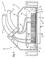
図1では、本実施形態において、二つの多重ワイヤケーブル14を含み、その各々が、接地線および信号線を含む(両方は示されず)、多重ワイヤケーブルアセンブリ12用コネクタシェル10の内部が示される。この実施形態では、ケーブル14は、同軸ケーブルを含む。しかしながら、遠距離通信用に公知の他の種類のケーブル、例えば双軸ケーブルまたはドレインワイヤケーブルを用いることができる。この種類のケーブルは、本発明に関連していない。コネクタシェル10は、二つのハウジング半部20、22を含むハウジング18を含み、その一方は図1に示され、一方その両方は図3に部分的に示される。ハウジング18の半部20、22は、金属製であり、よってファラデーケージとして設計される。固体金属ハウジング半部20、22の代替として、ハウジングを、導電性材料の層が設けられた非導電性材料(すなわち合成材料)で作ることができる。この導電性材料層は、以下で説明する接地プレートと(電気的かつ機械的)接触するために、ハウジング半部20、22の内側に配置されるべきである。
In FIG. 1, in this embodiment, two
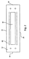
多重ワイヤケーブルアセンブリ12を受け取る、その上側に対向する、コネクタシェル10の下側に、導電性接地プレート24およびソケットコネクタ26によって被覆されるハウジング18の開口部が配置される。接地プレート24は、図2により詳細に示され、かつ二つの側端縁28ならびに二つの横端縁30を含む矩形である。接地プレート24の他の特徴を後で説明する。
An opening in the
接地プレート24は、ねじ32によってハウジング18に装着される。しかしながら、他の種類のメカニカルファスナーまたはクランプ等のような機械的締め付けシステムも用いることができる。また、溶接、付着等を、接地プレート24およびハウジング18の機械的接続のために用いることができる。
The
しかも、接地プレート24の前には、ハウジング18の開口部内に、ねじ34によってハウジング18に取り付けられるソケットコネクタ26が配置される。ソケットコネクタ26は、コンタクト要素46のアレイ44を形成するために横列および縦列に配置される複数の接地コンタクト要素40および信号コンタクト要素42を支持する、電気的絶縁材料のブロック36を含む。この実施形態では、アレイ46は、4横列のコンタクト要素46を含み、それらの二つは、接地コンタクト要素40を含み、他の二つは、信号コンタクト要素42を含む。
Moreover, in front of the
この実施形態では、コンタクト要素46は各々、ピン部48(雄部)、(接地コンタクト要素40のみに当てはまる)接地プレート24と摩擦係合することができる中央部50、および嵌め合いコネクタ要素(図示せず)の嵌め合いコンタクト要素のピン部と電気的接触するための他の部分52(ソケットすなわち雌部分)を含む。雌部分は、ブロック36に挿入される。上述しかつ図面に示したようなソケットコネクタ26は、当業者に基本的に公知である。
In this embodiment, each
図1に示されるように、ケーブル16の各々には、導電性材料のハウジング56を有する端子コネクタ54が設けられる。ハウジング56内には、ハウジング56に対して電気的絶縁され、かつ信号コンタクト要素42の一つに電気的に接続される信号コンタクト要素(図示せず)が配置される。しかも、ハウジング56内には、ハウジング56の信号コンタクト要素に対して電気的絶縁されかつハウジング56に電気的に接続される接地コンタクト要素(図示せず)、およびコンタクト要素46のアレイ44の接地コンタクト要素40の一つも配置される。図1ならびに図3では、端子コネクタ54は、一つの信号コンタクト要素および一つの接地コンタクト要素を含むSCIコネクタである。しかしながら、他の種類の端子コネクタ、特に、例えば二つの信号コンタクト要素および一つの共通接地コンタクト要素を含むような端子SCIコネクタも用いることができる。しかも、ケーブル16の導体はまた、例えばワイヤラッピングによってコンタクト要素46に直接接続することもできる。
As shown in FIG. 1, each
図1および図3から特に見られうるように、端子コネクタ54は、コンタクト要素アレイ44のコンタクト要素46を受け取る。この配置のために、ケーブル16の信号線は、信号コンタクト要素42に電気的に接続され、かつケーブル16の接地線は、コンタクト要素アレイ44の接地コンタクト要素40に接続される。図3に示されるように、端子コネクタ54は、該端子コネクタ54をコンタクト要素46から不注意に解除するのを防ぐために、ハウジング半部20、22の内面から突出し、かつ、端子コネクタ54のハウジング56の上方に配置されている突出リブ58によって適所に保持される。
As can be seen in particular from FIGS. 1 and 3, the
本発明の主たる態様の一つは、接地コンタクト要素40の接地プレート24との電気的接続、ならびに接地プレート24のハウジング18との電気的接続である。
One of the main aspects of the present invention is the electrical connection of the
図2からわかるように、接地プレート24は、中央切欠部分60、およびその両側に該切欠部60に隣接してかつ側端縁28に隣接して配置される2横列の貫通孔62を有するフレームのような形にされている。切欠部60は、コンタクト要素46のアレイ44の中央部分内に配置される信号コンタクト要素42の全てが、接地プレート24と接触することなく切欠部60を通して延在する(図3も参照)ような大きさにされている。それに対比して、接地プレート24の個々の貫通孔62は、接地コンタクト要素40の中央部分50が、貫通孔62内の接地プレート24と摩擦係合するような大きさを有する(図4参照)。よって、接地コンタクト要素40の全ては、ハウジング半部20、22の内面と接触する接地プレート24に接地され(図3参照)、よってその側端縁28の両方に沿って接地される。しかしながら、本発明にとっては、接地プレート24の側端縁28の一方が、ハウジング18の接地電位に電気的に接続され、本実施形態の該接地電位が、ハウジング半部20、22の一方によって与えられることが必要であるだけであることに留意されたい。
As can be seen from FIG. 2, the
図2からわかるように、接地プレート24に沿う接地経路、すなわち、貫通孔62と側端縁28との間の距離は、比較的短く、それにより、信号送信が非常に高速度で行なわれうるので、コネクタシェル10の電気性能が高められる。
As can be seen from FIG. 2, the ground path along the
図2による接地プレート24の設計は、複数の可能な設計の一つの代替に過ぎないことに留意されたい。例えば、コンタクト要素アレイ44はまた、二つの接地コンタクト要素の横列および二つの信号コンタクト要素の横列を含むこともあり、二つの接地コンタクト要素の横列は、互いに隣接してかつ二つの信号コンタクト要素の横列間に配置される。そのような配置では、その接地された側端縁の接地プレートは、接地プレートの接地された側端縁に隣接して位置決めされる信号コンタクト要素の横列の信号コンタクト要素が、それと接触することなく、それを通して延在する個々の貫通孔を含み、一方接地プレートは、接地された側端縁に対向するその側端縁で、他の信号コンタクト要素の横列の信号コンタクト要素が、それを通して延在する切欠部を含む。
Note that the design of the
最後に、コンタクト要素アレイ44の各横列内では、交互に大小貫通孔が配置されることも可能である。小貫通孔は、接地コンタクト要素と摩擦係合しており、一方大貫通孔は、信号コンタクト要素が、接地プレートに機械的かつ電気的に接続することなく、それを通して延在する。
Finally, in each row of the
本発明を、その特定の例証的な実施形態に関連して記載しかつ図示したが、本発明がこの例証的な実施形態に限られることは意図していない。当業者は、変形および変更が、冒頭の特許請求の範囲によって画定されるような発明の範囲から逸脱することなくなされうることを認識しよう。したがって、本発明内に、添付の特許請求の範囲およびその均等物の範囲内に入るものとして、そのような変形および変更の全てを含むことが意図されている。 Although the present invention has been described and illustrated with reference to specific illustrative embodiments thereof, it is not intended that the invention be limited to this illustrative embodiment. Those skilled in the art will recognize that variations and modifications can be made without departing from the scope of the invention as defined by the appended claims. Accordingly, it is intended to embrace all such variations and modifications as fall within the scope of the appended claims and their equivalents.
しかも、接地プレート24の前には、ハウジング18の開口部内に、ねじ34によってハウジング18に取り付けられるソケットコネクタ26が配置される。ソケットコネクタ26は、コンタクト要素46のアレイ44を形成するために横列および縦列に配置される複数の接地コンタクト要素40および信号コンタクト要素42を支持する、電気的絶縁材料のブロック36を含む。この実施形態では、アレイ44は、4横列のコンタクト要素46を含み、それらの二つは、接地コンタクト要素40を含み、他の二つは、信号コンタクト要素42を含む。
Moreover, in front of the
Claims (19)
接地電位を有するハウジング(18)と、
長手方向アレイ(44)に配置される多数のコンタクト要素(46)であって、前記コンタクト要素(46)は、嵌め合いコネクタのコンタクト要素と電気的接触するために設けられ、かつ
(i)前記多重ワイヤケーブルアセンブリの前記接地線に接続するための接地コンタクト要素(40)と、
(ii)前記多重ワイヤケーブルアセンブリの前記信号線に接続するための信号コンタクト要素(42)とを含む、コンタクト要素(46)と、
前記コンタクト要素(46)の前記アレイ(44)に沿ってかつその長手方向に延在する長手方向接地プレート(24)であって、前記接地プレート(24)は、二つの側端縁(28)を有し、少なくともその一方は、前記ハウジング(18)の前記接地電位との電気的接続のために設けられる、長手方向接地プレート(24)と、を含み、
前記接地プレート(24)は、前記接地コンタクト要素(40)がそれを通して延在する貫通孔(62)を含み、かつ
前記貫通孔(62)では、前記接地コンタクト要素(40)は、前記接地プレート(24)に電気的に接続される、コネクタシェル。 A connector shell for a multi-wire cable assembly having a plurality of ground wires and signal wires, the connector shell comprising:
A housing (18) having a ground potential;
A number of contact elements (46) disposed in the longitudinal array (44), wherein the contact elements (46) are provided for electrical contact with the mating connector contact elements; and A ground contact element (40) for connection to the ground wire of a multi-wire cable assembly;
(Ii) a contact element (46) comprising a signal contact element (42) for connection to the signal line of the multi-wire cable assembly;
A longitudinal ground plate (24) extending along and in the longitudinal direction of the array (44) of the contact elements (46), the ground plate (24) comprising two side edges (28) At least one of which includes a longitudinal ground plate (24) provided for electrical connection with the ground potential of the housing (18);
The ground plate (24) includes a through hole (62) through which the ground contact element (40) extends, and in the through hole (62), the ground contact element (40) includes the ground plate A connector shell electrically connected to (24).
The contact element is (1) a housing of conductive material, i.e., disposed within the housing and electrically insulated relative to the housing and electrically connected to a signal element of the array of contact elements. One signal contact element; (2) not only disposed within the housing but also electrically connected thereto, and is electrically insulated relative to the signal contact element of the housing and of the array of contact elements 19. A connector shell according to any one of the preceding claims, provided for receiving a terminal connector having at least one ground contact element electrically connected to the ground contact element.
Applications Claiming Priority (3)
| Application Number | Priority Date | Filing Date | Title |
|---|---|---|---|
| EP03019714 | 2003-08-29 | ||
| EP03019714.9 | 2003-08-29 | ||
| PCT/US2004/023625 WO2005025010A1 (en) | 2003-08-29 | 2004-07-22 | Connector shell for a multiple wire cable assembly |
Publications (2)
| Publication Number | Publication Date |
|---|---|
| JP2007534110A true JP2007534110A (en) | 2007-11-22 |
| JP2007534110A5 JP2007534110A5 (en) | 2008-01-10 |
Family
ID=34259150
Family Applications (1)
| Application Number | Title | Priority Date | Filing Date |
|---|---|---|---|
| JP2006524659A Withdrawn JP2007534110A (en) | 2003-08-29 | 2004-07-22 | Connector shell for multi-wire cable assembly |
Country Status (8)
| Country | Link |
|---|---|
| EP (1) | EP1661214A1 (en) |
| JP (1) | JP2007534110A (en) |
| KR (1) | KR20060067965A (en) |
| CN (1) | CN1846333B (en) |
| BR (1) | BRPI0413877A (en) |
| IL (1) | IL173687A0 (en) |
| WO (1) | WO2005025010A1 (en) |
| ZA (1) | ZA200602553B (en) |
Families Citing this family (1)
| Publication number | Priority date | Publication date | Assignee | Title |
|---|---|---|---|---|
| EP1887659A1 (en) | 2006-08-07 | 2008-02-13 | 3M Innovative Properties Company | Electrical connection for coaxial cables |
Family Cites Families (10)
| Publication number | Priority date | Publication date | Assignee | Title |
|---|---|---|---|---|
| US4820201A (en) * | 1987-08-24 | 1989-04-11 | G & H Technology, Inc. | Cable shield termination for an electrical connector |
| JPH0821450B2 (en) * | 1987-10-05 | 1996-03-04 | 日本電気株式会社 | High-speed signal connector |
| US4889500A (en) * | 1988-05-23 | 1989-12-26 | Burndy Corporation | Controlled impedance connector assembly |
| US5221215A (en) * | 1990-06-26 | 1993-06-22 | Foxconn International, Inc. | User configurable integrated electrical connector assembly with improved means for preventing axial movement |
| US5116230A (en) * | 1991-04-09 | 1992-05-26 | Molex Incorporated | Coaxial cable connector |
| DE9113003U1 (en) * | 1991-10-18 | 1992-06-11 | Moll, Hans, 7996 Meckenbeuren, De | |
| GB9712457D0 (en) * | 1997-06-17 | 1997-08-20 | Smiths Industries Plc | Electrical connection |
| US5975953A (en) * | 1997-08-29 | 1999-11-02 | Hewlett-Packard Company | EMI by-pass gasket for shielded connectors |
| US6171143B1 (en) * | 1998-04-24 | 2001-01-09 | Nortel Networks Limited | Multiple coaxial cable connector |
| TW539307U (en) * | 1999-08-24 | 2003-06-21 | Hon Hai Prec Ind Co Ltd | Plug connector |
-
2004
- 2004-07-22 CN CN2004800248980A patent/CN1846333B/en not_active Expired - Fee Related
- 2004-07-22 JP JP2006524659A patent/JP2007534110A/en not_active Withdrawn
- 2004-07-22 WO PCT/US2004/023625 patent/WO2005025010A1/en active Search and Examination
- 2004-07-22 EP EP04778917A patent/EP1661214A1/en not_active Withdrawn
- 2004-07-22 BR BRPI0413877-5A patent/BRPI0413877A/en not_active IP Right Cessation
- 2004-07-22 KR KR1020067003922A patent/KR20060067965A/en active IP Right Grant
-
2006
- 2006-02-13 IL IL173687A patent/IL173687A0/en unknown
- 2006-03-28 ZA ZA200602553A patent/ZA200602553B/en unknown
Also Published As
| Publication number | Publication date |
|---|---|
| BRPI0413877A (en) | 2006-10-24 |
| KR20060067965A (en) | 2006-06-20 |
| IL173687A0 (en) | 2006-07-05 |
| ZA200602553B (en) | 2007-07-25 |
| WO2005025010A1 (en) | 2005-03-17 |
| CN1846333B (en) | 2010-12-01 |
| EP1661214A1 (en) | 2006-05-31 |
| CN1846333A (en) | 2006-10-11 |
Similar Documents
| Publication | Publication Date | Title |
|---|---|---|
| EP2250707B1 (en) | High-speed backplane connector | |
| US8840432B2 (en) | Circuit board and wire assembly | |
| US5509827A (en) | High density, high bandwidth, coaxial cable, flexible circuit and circuit board connection assembly | |
| US6910897B2 (en) | Interconnection system | |
| US7090501B1 (en) | Connector apparatus | |
| US7677927B2 (en) | High bandwidth connector | |
| JP2007525808A (en) | Connector device | |
| JPH04220977A (en) | Connector assembled body of printed circuit board | |
| US5151036A (en) | Connectors with ground structure | |
| US20100065327A1 (en) | Cable assembly with molded grounding bar and method of making same | |
| KR20100068002A (en) | Connector for coaxial cable | |
| US5141453A (en) | Connectors with ground structure | |
| JP2017004945A (en) | Plug or socket as component of electrical connector, and electrical connector | |
| US20110287642A1 (en) | Cable connector assembly employing separate inter connecting conductors and method for assembling the same | |
| CN113725664A (en) | Plug connector capable of being inserted into socket connector in sliding mode | |
| US7854626B2 (en) | Connection structure for small diameter shielded cable | |
| US7273393B2 (en) | Connector shell for a multiple wire cable assembly | |
| US6971896B2 (en) | Flex strips for high frequency connectors | |
| US7011545B2 (en) | Socket connector for receiving a plurality of termination sockets for coaxial cables | |
| JP2007534110A (en) | Connector shell for multi-wire cable assembly | |
| CN113725642A (en) | Connector assembly comprising a socket connector and a plug connector | |
| WO1999019213A2 (en) | Assembly for splicing multiple screened cables | |
| CN116686172A (en) | Plug connector and connector assembly comprising a socket connector and a plug connector | |
| GB2383475A (en) | Impedance matching cable connector |
Legal Events
| Date | Code | Title | Description |
|---|---|---|---|
| A761 | Written withdrawal of application |
Free format text: JAPANESE INTERMEDIATE CODE: A761 Effective date: 20080613 |