JP2007509357A - Quality assurance method for long materials - Google Patents
Quality assurance method for long materials Download PDFInfo
- Publication number
- JP2007509357A JP2007509357A JP2006536995A JP2006536995A JP2007509357A JP 2007509357 A JP2007509357 A JP 2007509357A JP 2006536995 A JP2006536995 A JP 2006536995A JP 2006536995 A JP2006536995 A JP 2006536995A JP 2007509357 A JP2007509357 A JP 2007509357A
- Authority
- JP
- Japan
- Prior art keywords
- long
- length
- long material
- inspection
- square
- Prior art date
- Legal status (The legal status is an assumption and is not a legal conclusion. Google has not performed a legal analysis and makes no representation as to the accuracy of the status listed.)
- Pending
Links
Images


Classifications
-
- B—PERFORMING OPERATIONS; TRANSPORTING
- B27—WORKING OR PRESERVING WOOD OR SIMILAR MATERIAL; NAILING OR STAPLING MACHINES IN GENERAL
- B27M—WORKING OF WOOD NOT PROVIDED FOR IN SUBCLASSES B27B - B27L; MANUFACTURE OF SPECIFIC WOODEN ARTICLES
- B27M3/00—Manufacture or reconditioning of specific semi-finished or finished articles
- B27M3/0013—Manufacture or reconditioning of specific semi-finished or finished articles of composite or compound articles
- B27M3/002—Manufacture or reconditioning of specific semi-finished or finished articles of composite or compound articles characterised by oblong elements connected at their ends
-
- B—PERFORMING OPERATIONS; TRANSPORTING
- B27—WORKING OR PRESERVING WOOD OR SIMILAR MATERIAL; NAILING OR STAPLING MACHINES IN GENERAL
- B27G—ACCESSORY MACHINES OR APPARATUS FOR WORKING WOOD OR SIMILAR MATERIALS; TOOLS FOR WORKING WOOD OR SIMILAR MATERIALS; SAFETY DEVICES FOR WOOD WORKING MACHINES OR TOOLS
- B27G1/00—Machines or devices for removing knots or other irregularities or for filling-up holes
-
- B—PERFORMING OPERATIONS; TRANSPORTING
- B27—WORKING OR PRESERVING WOOD OR SIMILAR MATERIAL; NAILING OR STAPLING MACHINES IN GENERAL
- B27M—WORKING OF WOOD NOT PROVIDED FOR IN SUBCLASSES B27B - B27L; MANUFACTURE OF SPECIFIC WOODEN ARTICLES
- B27M3/00—Manufacture or reconditioning of specific semi-finished or finished articles
- B27M3/0013—Manufacture or reconditioning of specific semi-finished or finished articles of composite or compound articles
- B27M3/006—Manufacture or reconditioning of specific semi-finished or finished articles of composite or compound articles characterised by oblong elements connected both laterally and at their ends
-
- G—PHYSICS
- G01—MEASURING; TESTING
- G01N—INVESTIGATING OR ANALYSING MATERIALS BY DETERMINING THEIR CHEMICAL OR PHYSICAL PROPERTIES
- G01N3/00—Investigating strength properties of solid materials by application of mechanical stress
- G01N3/08—Investigating strength properties of solid materials by application of mechanical stress by applying steady tensile or compressive forces
-
- G—PHYSICS
- G01—MEASURING; TESTING
- G01N—INVESTIGATING OR ANALYSING MATERIALS BY DETERMINING THEIR CHEMICAL OR PHYSICAL PROPERTIES
- G01N33/00—Investigating or analysing materials by specific methods not covered by groups G01N1/00 - G01N31/00
- G01N33/46—Wood
Abstract
本発明は、連続的に生産され、所定の最小値の長さ(12)を有し、適切にフィンガージョイント接合された長材(1)の品質を保証する方法に関する。上記方法は、上記長さ(12)以下に生産されたそれぞれの木片は、その端域(5)に、欠陥の無い長材が破損する値未満である閾値まで張力が負荷され、その上、測定した長材片の部分又は全体の長さに対する長さの変化(△l)を、該長材(1)を利用又は更なる加工する際の品質基準の分類に用いることを特徴とする。さらに本発明は、上記方法を実施する装置にも関する。 The present invention relates to a method for guaranteeing the quality of a long piece (1) produced continuously, having a predetermined minimum length (12) and appropriately finger-joined. The above method is such that each piece of wood produced below the length (12) is tensioned to its end region (5) to a threshold that is less than the value at which the defect-free long material breaks, The change in length (Δl) with respect to the length of the long piece or the whole length of the measured long piece is used for classification of quality standards when the long piece (1) is used or further processed. The invention further relates to an apparatus for carrying out the method.
Description
本発明は、連続的に生産され、所定の最小値の長さを有し、フィンガージョイント接合された材木に好適な、品質の保障方法に関するものであり、より詳しくは、構造用材木に関するものである。また、上記方法を実行する装置に関する。 The present invention relates to a quality assurance method suitable for a timber produced continuously, having a predetermined minimum length, and finger-joined, and more particularly to a structural timber. is there. Moreover, it is related with the apparatus which performs the said method.
樹木の幹から、例えば構造用材木などに用いられる高品質の長材を製造するためには、一律の品質を適正に確保しつつ、樹木の幹をそれぞれ所定の寸法に切断し、整形し、もし原木が、例えば枝が折れた箇所のように脆弱部として分かっている欠点を示し、よって破損する場合には、これら欠点や脆弱部は、それぞれ除去され、残存する原木の木片は、長材の正面にフィンガージョイントすることにより接着され、長材が形成される。このようにして、接着集成材は、板材を互いに接着した複数の層からなる材木を、長手方向に、指を互いに埋め合わせるようにつなぎあわせることで製造される。集成角材は、2、3本の角材を、互いに長手方向に接着することにより製造される。上記角材は、同様に、フィンガージョイントによりつなぎ合わされた部分を含むこともある。 In order to produce high-quality long wood used for structural timber, for example, from the trunk of the tree, while ensuring uniform quality appropriately, each tree trunk is cut into predetermined dimensions, shaped, If the log shows a defect that is known as a weak part, for example, where a branch is broken, and thus breaks, the defect and the weak part are removed respectively, and the remaining wooden piece of A long material is formed by bonding by finger jointing to the front surface. In this way, the adhesive laminated material is manufactured by joining together timbers composed of a plurality of layers obtained by adhering plate materials to each other so that fingers are buried in the longitudinal direction. The laminated square bar is manufactured by bonding two or three square bars to each other in the longitudinal direction. Similarly, the square member may include portions joined by finger joints.
硬材の加工に関しては特別の問題が生じる。これらの木は人の胸の高さで約50cm以上の直径をなす。このような硬材を構造用材木に加工することは、生産率の向上いう利点を得る。しかしながら、木材の特性はとても不均一になる。換言すれば、硬材は高度の選別作業を必要とする。さらに、水分を含んだ芯や、芯材のひび割れは様々な問題を引き起こす。同様に、硬い枝は、機械の性能を劣化させる。このため、硬材から製造された長材は、まれに、一本の木の幹から一木材片が切り取られるだけであり、長材を形成するためには、ほとんどの場合、上述のように、脆弱部を切除してフィンガージョイントにより接合することが必要となる。 Special problems arise with the processing of hardwood. These trees are about 50 cm in diameter at the height of a person's chest. Processing such a hardwood into a structural timber has the advantage of improving the production rate. However, the properties of wood are very uneven. In other words, hard materials require a high degree of sorting. Furthermore, the core containing moisture and cracking of the core material cause various problems. Similarly, hard branches degrade machine performance. For this reason, rare materials produced from hardwood rarely have only one piece of wood cut off from a single tree trunk. In most cases, as described above, It is necessary to cut the fragile part and join it with a finger joint.
この加工の内、幾分かを自動化された工法により実施されることは知られている。たとえば、木は最初に品質選別工程を通過する。その工程は水分、年輪密度、色や模様などの品質、枝などを検査する。この工程は視覚によっても可能であり、湿潤度測定を電気抵抗測定によることも可能である。又、レーザーカメラを用いても可能である。隠れた枝を検知するために、エックス線、コンピューター断層撮影、超音波技術が用いられる。欠点の切除や、フィンガージョイント接合による接着は、多くの場合、自動制御された設備によって行われる。 It is known that some of this processing is performed by an automated method. For example, wood first goes through a quality sorting process. The process inspects moisture, annual ring density, quality such as color and pattern, and branches. This process can also be performed visually, and the wetness measurement can also be performed by electrical resistance measurement. It is also possible to use a laser camera. X-rays, computed tomography, and ultrasound techniques are used to detect hidden branches. In many cases, defect removal and finger joint bonding are performed by automatically controlled equipment.
そのような設備によって加工されたフィンガージョイント接合の品質を保証するため、破壊検査が実施される。そして、そのような破壊検査に必要な曲げ試験では、フィンガージョイントする領域に、少しの破損箇所の発生も許されない。 Destructive inspection is performed to ensure the quality of finger joint joints processed by such equipment. In the bending test necessary for such a destructive inspection, the occurrence of a slight breakage point is not allowed in the finger joint region.
この方法により製造された長材を用いると、自動化された誤差検出方法を用い、また、材木が構造物を支える役割を担う木造構造物から、構造用材木を取り除くことを試みるために、念入りに視覚検査を行なったとしても、予期せぬ破損が生じることが分かっている。例えば、風などによる木の加圧破壊、接着誤差、噛み合わせ誤差、内部のひび割れなどに寄って生じる破損である。これは特に不都合であり、このため、もはや、硬材から作られた角材を安価に利用することは可能ではない。すなわち、隠れた又は検出されない欠点や脆弱部を含む硬材は、集成材又は集成角材を多層化したものにおいて、それぞれ、多層に接着することで、重要性の少なくなる部分に個別に加工処理するべきである。 When using long timber produced by this method, an automated error detection method is used, and in order to attempt to remove structural timber from a wooden structure where the timber is responsible for supporting the structure, Even visual inspection has been shown to cause unexpected damage. For example, damage caused by pressure breakage of trees due to wind, adhesion error, engagement error, internal cracks, and the like. This is particularly inconvenient and for this reason it is no longer possible to inexpensively use squares made from hardwood. In other words, hard materials that contain hidden or undetectable defects or fragile parts are individually processed into less important parts by adhering multiple layers of laminated or laminated timber to each other. Should.
本発明の目的は、たとえ、長材が、集成材、集成角材、構造用材木、集成片材、集成合板の形態により形成されていたとしても、これら長材を、強い応力を受ける構造部に対して、有効に利用することを可能とする、連続的に生産される長材の品質保証方法を提供することにある。特に、現在、材木の不均一性のために要求されている、断面にかかる荷重を、大きく減少させることを目的としている。 The object of the present invention is that even if the long members are formed in the form of laminated timber, laminated timber, structural timber, laminated timber, laminated plywood, these long members are made into structural parts that receive strong stress. On the other hand, it is an object of the present invention to provide a quality assurance method for continuously produced long materials that can be used effectively. In particular, the present invention aims to greatly reduce the load applied to the cross-section, which is currently required for the non-uniformity of timber.
森林においては、硬材が優勢的に存在しており、硬材の量はさらに増加している。そこで、本発明は、特に、この硬材を単に利用可能とするのみにとどまらない。構造物を支える役目を長材が担う構造物であって、現在、一本の構造用材木として形成された長材が用いられており、例えば、長手方向に互いに個々の材木が接合された長材は用いられていない構造物であって、高い応力を受ける構造物に対して、要求される安全性を備えた上で、まさにこの硬材を利用可能とすることを目的としている。 In forests, hardwood is predominant and the amount of hardwood is increasing further. Therefore, the present invention is not limited to merely making this hard material particularly usable. A structure in which long members play the role of supporting a structure, and long members formed as a single structural lumber are currently used. For example, long members in which individual timbers are joined together in the longitudinal direction. The material is a structure that is not used, and is intended to make it possible to use this hard material with the required safety against a structure subjected to high stress.
本発明によれば、上記の目的は、以下により達成される。所定の最小値の長さを有し、連続的に生産され、適切にフィンガージョイント接合した長材であって、特に構造用材木の品質を保証する方法において、上記の長さ以下に調製された各長材であって、適切かつ完全に接合された長材に対して、上記長材のそれぞれの端を押さえて、張力を与える工程と、その後、欠陥のない長材が破損する負荷を超えることのない閾値まで張力を増加する工程と、上記の処理に伴い増加する長材の長さの変化を少なくとも一部分あるいはその長材の全長にわたって測定する工程と、上記変化を、上記長材の利用において、又は、その他のさらなる処理において、品質基準として使用する工程とを含むことを特徴とする方法。 According to the present invention, the above object is achieved by the following. A length of a predetermined minimum value, continuously produced and appropriately finger-joined long material, especially prepared in a way that guarantees the quality of structural timber below this length A process of applying tension by pressing each end of the long material to each of the long materials appropriately and completely joined, and then exceeding the load that breaks the long material without defects. A step of increasing the tension to a constant threshold, a step of measuring a change in the length of the long material that increases with the above processing at least in part or over the entire length of the long material, and the use of the long material. Or as a quality criterion in other further processing.
本発明は、木材の張力試験において、長さの変化と、張力との間における相関性の高い線形性により、破壊限度を超えない範囲において、長材における特性の劣化が生じないことを見出した事実に基づく。 In the tension test of wood, the present invention has found that due to the linearity having a high correlation between the change in length and the tension, there is no deterioration in properties in the long material within a range not exceeding the fracture limit. Based on the facts.
これにより、長さの変化を測定するために、レーザースペックル法や、差動長さ測定法が、直接測定法と共に、好適に用いられる。あるいは、例えば、引っ張る範囲における抵抗の変化における抵抗変化のような間接測定法を用いても良い。 Thereby, in order to measure the change in length, the laser speckle method and the differential length measurement method are preferably used together with the direct measurement method. Alternatively, for example, an indirect measurement method such as resistance change in resistance change in a pulling range may be used.
上記長材が破損した場合において、破損する間に測定した負荷張力は、破損した木片をさらに利用する又は加工に用いるための品質の分類に用いることが好ましい。 When the long material is damaged, the load tension measured during the breakage is preferably used for classification of quality for further use of the broken piece of wood or for use in processing.
所定の張力を付与することにより、上記長材に係る長さの変化が定められた許容範囲を越して大きくなる場合、上記長材を、生産工程から除去し、許容外の長さの変化又は長材の脆弱部の原因となる長材に係る脆弱部を、それぞれ切り出し、脆弱部を除去した残余部分を、フィンガージョイント接合によって新たな長材に集成し、適宜、更に長い長材断片を加えた上で、新たな長材を製造し、再度請求項1に記載の方法に供することを特徴としていても良い。
When applying a predetermined tension, when the change in the length of the long material becomes larger than a predetermined allowable range, the long material is removed from the production process, and an unacceptable length change or Cut out the fragile parts of the long material that cause the fragile parts of the long material, and gather the remaining parts from which the fragile parts were removed into new long materials by finger joint joining, and add longer pieces of long material as appropriate. In addition, a new long material may be manufactured and used for the method according to
上述した事実によれば、張力検査は生産過程において、破損限度(破壊限度を決定する検査)まで行なうことができる。該検査の結果は、破損時の応力を示す。破損箇所が切除され、上記破損物が、例えば、フィンガージョイント結合によって再び接合され、接合が完全である場合、再度の張力試験において、少なくとも上記は損限度では、2度と破損は生じない。なぜなら、該材木に係る他の箇所は、既に問題なく検査を通過しているからである。全材料の長さを維持するため、高品質の新しい部分は、破損部分の除去後、挿入される。しかし、そのようにすると、繰り返し破損が生じるという高いリスクが生じる(検査されていない材料における、2つの接合点)。そこで適切に、張力負荷を大幅に減少させて、しかし、要求される所望の強度ために十分な負荷で、2回目の張力検査が行われる。破損物が次の工程に移るために十分な大きさであれば、こうして得られた木材は、破損部の端を切除した後に、十分に直接検査されたものとみなすことができる。よって、2回目の張力検査は省略できる。 According to the fact described above, the tension inspection can be performed up to the breakage limit (inspection for determining the breakage limit) in the production process. The result of the inspection indicates the stress at breakage. If the breakage is excised and the breakage is rejoined, for example by finger joint bonding, and the bond is complete, the re-tension test will not break at least twice at the loss limit. This is because the other parts of the timber have already passed the inspection without any problem. In order to maintain the length of the entire material, a high quality new part is inserted after removal of the broken part. However, doing so creates a high risk of repeated failure (two junctions in the untested material). Accordingly, a second tension test is performed with a substantial reduction in tension load, but with sufficient load for the desired strength required. If the breakage is large enough to move on to the next step, the wood thus obtained can be considered to have been inspected sufficiently directly after cutting off the end of the breakage. Therefore, the second tension inspection can be omitted.
このような測定により、張力検査の間に除外した長材を、該生産工程中に、再度、好適に導入することができる。そして、材木の有効活用が可能となり、大量の廃棄物及び/又伐採を、可能な限り小さくすることができる。 By such a measurement, the long material excluded during the tension inspection can be suitably introduced again during the production process. And timber can be used effectively, and a large amount of waste and / or logging can be made as small as possible.
また、長材の両端であって二つの対向する端域に備えられた締付け顎を介して、長材に張力を加えることが好ましい。 Moreover, it is preferable to apply tension to the long material via the clamping jaws provided at the opposite ends of the long material.
より好ましくは、検査した木材に、それぞれ品質マークをつけるとよい。 More preferably, a quality mark is attached to each of the inspected wood.
また、例えば、平削り、研削、研磨のような最終機械工程を、検査の後に実施することが好ましい。 In addition, it is preferable to carry out final machine steps such as planing, grinding, and polishing after the inspection.
上記長さ変化の測定結果に基づいて、少なくとも2種類の品質分類に長材を割り当てることで、強度における特定の個々の要求に対して、最適な製品を提供することが可能となること、及び、最も高い要求を充たさない長材の有効利用が可能となるという利点を有することが分かった。 By assigning long materials to at least two types of quality classifications based on the measurement results of the length change, it becomes possible to provide an optimum product for specific individual requirements in strength, and It has been found that there is an advantage that it is possible to effectively use a long material that does not satisfy the highest demand.
また、原材料の表面を解析した後、分断していない原材料及び/又は複数の木片に分断した原材料を品質分類毎に整理し、各品質分類に係る長材を、又はフィンガージョイント接合した該長材を、請求項1に記載の品質保証方法に供することが好ましい。
In addition, after analyzing the surface of the raw material, the raw material that has not been divided and / or the raw material that has been divided into a plurality of pieces of wood are arranged for each quality classification, and the long material according to each quality classification, or the long material that has been joined by finger joints Is preferably subjected to the quality assurance method according to
本発明の更なる目的は、品質保証された長材によって造る木造構造物のための、角材及び結合材を製造する方法を提供することである。また、極めて大きい断面を有することにより、少なくとも集成材より作られる接着集成材と同等に、該構造物を支える役目を果たし、好ましくはより高い耐久力を有する角材及び結合材を製造する方法を提供することである。 It is a further object of the present invention to provide a method for producing squares and binders for wooden structures built with quality-guaranteed long members. In addition, by providing an extremely large cross section, it provides a method of manufacturing a square member and a bonding member that serve to support the structure at least as much as an adhesive laminated member made from a laminated member, and preferably have higher durability. It is to be.
本発明によれば、上記更なる目的は、請求項1に記載の検査を受け、利用の際に要求される品質基準に適合した、少なくとも2本の長材を互いに接着して、垂直接着接合部を備える角材を形成することで達成される。
According to the present invention, the further object is to perform vertical adhesive bonding by adhering at least two long materials that have undergone the inspection according to
このようにして、上記長材は、角材を形成する前に、請求項1記載の品質を保証する検査に供され、その横の全長を検査することが重要である。これにより、既存の角材、例えば、従来の方法による板材と少なくとも同等の品質を有する硬材を利用することが可能となる。
Thus, it is important that the long material is subjected to the inspection for assuring the quality according to
角材を形成するための長材に、特に適する接着剤及び粘着剤は、それぞれ、長材の長手方向の側面であって、互いに接着する側面を、接着前に研磨することで、確認できる。 Adhesives and pressure-sensitive adhesives that are particularly suitable for the long member for forming the square member can be confirmed by polishing the side surfaces in the longitudinal direction of the long member, which are bonded to each other before bonding.
角材に要求される耐久力によっては、3以上の長材を互いに隣接させて接着し、角材を形成することもできる。 Depending on the durability required for the square bar, three or more long bars can be bonded adjacent to each other to form the square bar.
本発明により製造された角材から、接合材を形成するためには、上部に垂直方向の接着接合部を備える角材を、それぞれ互いに接着することで、結合角材を形成することが好ましい。 In order to form a bonding material from the square bar manufactured according to the present invention, it is preferable to form a bonded square bar by bonding the square bars each having a vertical adhesive bonding portion on the upper part thereof.
本発明の方法により製造された角材は、少なくとも一つの垂直方向の接着接合部と、形成した上記接着接合部の側面を適切に研磨することを特徴としている。 The square bar manufactured by the method of the present invention is characterized by appropriately polishing at least one vertical adhesive joint and the side surface of the formed adhesive joint.
2以上の角材を、それぞれ他方の表面に配置し、互いに接着することで形成されることが好ましい。 It is preferable that two or more square members are respectively disposed on the other surface and bonded together.
本発明によれば、該木造構造物に特別な外観上の利点を得ることができる。特に、角材又は結合角材における垂直方向の側面に、細い板を互いに接着しただけの接着接合部を含む接着集成材よりも、まだら模様を表す。 According to the present invention, a special appearance advantage can be obtained for the wooden structure. In particular, it represents a mottled pattern rather than an adhesive assembly that includes an adhesive joint that is simply bonded to thin plates on the side surfaces in the vertical direction of the square or bonded square.
角材および結合角材は、好ましくは、高さは100mm以上であって、好ましくは300mm以下であり、幅は50mm以上であって、好ましくは100mm以下である長材からなることを特徴としている。 The square bar and the bonded square bar are preferably characterized by being made of a long bar having a height of 100 mm or more, preferably 300 mm or less, and a width of 50 mm or more, preferably 100 mm or less.
担体の高い応力を受ける領域に、木の幹における辺材のさらに高い強度域を用いるために、好ましい実施の形態に従って、高さは300mm以上であって、好ましくは600mm以下であり、幅は50mm以上である長材であって、硬材の辺材から切り離された幅の狭い端域を備える上記長材からなる角材又は結合角材であることを特徴としている。 According to a preferred embodiment, the height is 300 mm or more, preferably 600 mm or less, and the width is 50 mm, in order to use the higher strength region of the sapwood in the trunk of the tree in the area subject to high stress of the carrier. It is the above-mentioned long material, and is characterized in that it is a square material or a bonded square material made of the above-mentioned long material having a narrow end region separated from a hard material side material.
角材又は結合角材の底側及び/又は上側においてもまだら模様を確保するため、角材又は結合角材は、その幅の全長にわたって、底側及び/又は上側に少なくとも一つの長材を配置して接着し、それぞれ請求項1に記載の方法と同様に検査し、それぞれの底又は上にまだら模様を示すことを特徴としている。
In order to secure a mottled pattern on the bottom side and / or top side of the square bar or bonded square bar, the square bar or bonded square bar is bonded by placing at least one long bar on the bottom side and / or upper side over the entire length of the width. , Each of which is inspected in the same manner as in the method of
該検査を実行するための装置は、長材に張力を加える張力検査設備であり、長材に取り付ける締付け顎を備え、上記締付け顎の面には溝が設けられ、上記溝は、その断面形状が弓形、好ましくは、円弧状の弓形であり、荷重方向に横断するように設けられていることを特徴としている。 The apparatus for performing the inspection is a tension inspection facility that applies tension to the long material, and includes a fastening jaw attached to the long material, and a groove is provided on a surface of the fastening jaw, and the groove has a cross-sectional shape. Is an arcuate shape, preferably an arcuate arcuate shape, characterized in that it is provided so as to cross the load direction.
より良好に力を伝えるために、隣接する溝は異なる深さを有し、隣接する上記溝は、その断面において、異なる曲率及び異なる幅を示す。 In order to transfer force better, adjacent grooves have different depths, and the adjacent grooves exhibit different curvatures and different widths in their cross-section.
検査を受ける長材が締付け顎によって損傷することを避けるため、上記締付け顎は、好ましい実施の形態に従って、より大きい深さ、より大きい幅、より顕著に小さい曲率を有する溝を、常に、より小さい深さ、より小さい幅、より顕著に大きい曲率を有する溝の隣に備えることを特徴としている。さらに、2種の上記溝は、互いに隣接することが好ましい。 In order to avoid damaging the long material to be inspected by the clamping jaws, the clamping jaws are always smaller in grooves having a greater depth, a larger width, a significantly smaller curvature, according to a preferred embodiment. It is characterized by being provided next to a groove having a depth, a smaller width and a significantly larger curvature. Further, the two types of grooves are preferably adjacent to each other.
さらに、本発明は、連続的に生産される木片を検査するための木材の張力検査装置を提供することを目的にしている。具体的には、長材がたとえ集成材、集成角材、構造用材木、集成片材、集成合板の形態をなしていても、強い応力を受ける構造部に対して、有効に利用することを可能とするために該装置が提供される。特に、その木材の不均一性のために現在必要とされる断面荷重を大きく減少させる必要がある。 It is another object of the present invention to provide a wood tension inspection apparatus for inspecting continuously produced pieces of wood. Specifically, even if the long material is in the form of laminated timber, laminated timber, structural timber, laminated timber, laminated plywood, it can be used effectively for structural parts that receive strong stress. The apparatus is provided for: In particular, the cross-sectional load currently required due to the non-uniformity of the wood needs to be greatly reduced.
森林においては、硬材が優勢的に存在しており、硬材の量はさらに増加している。そこで、本発明は、特に、現在、一の構造用材木として形成された長材が用いられており、長手方向に互いに個々の材木が接合された長材が用いられていない、この硬材に対する木材張力検査装置を提供することにある。 In forests, hardwood is predominant and the amount of hardwood is increasing further. Therefore, the present invention is particularly applicable to this hardwood, in which a longwood formed as one structural lumber is currently used, and no longwood in which individual lumbers are joined to each other in the longitudinal direction is used. It is to provide a wood tension inspection device.
本発明によれば、上記目的は、
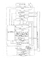
検査する長材片における最大の長さに対応する長さを有する検査用台座、特に動力台座と、上記検査用台座の端域に設けられ、好ましくは固定して設けられている第一の引っ張り架台と、上記検査用台座に沿って可動で、検査される長材片における長さに対して調整可能な引っ張り架台と、上記引っ張り架台の両方に設けられ、検査位置に運ばれた長材の断片を、上方及び下方から掴んで固定する締付け顎と、上記引っ張り架台によって固定された長材片に力を加える装置と、検査用台座の横に位置し長材片の緩衝領域から、検査用台座に、そして、上記検査用台座に対して上記緩衝領域の反対側に位置し検査後の長材片を蓄える蓄積領域に、長材片を運ぶ横断コンベヤーと、締付け顎間の検査位置に運ばれた長材片を中央に寄せる中央寄せ手段との構成を組み合わせることで達成される。
According to the invention, the object is
An inspection pedestal having a length corresponding to the maximum length of the long piece of material to be inspected, in particular a power pedestal, and a first tension provided in the end region of the inspection pedestal, preferably fixed. It is movable along the pedestal, the inspection pedestal, and is adjustable on the length of the long piece of material to be inspected, and the length of the long material carried to the inspection position. A clamping jaw for gripping and fixing the fragment from above and below, a device for applying a force to the long piece fixed by the above-mentioned pulling base, and a buffering area for the long piece, located next to the inspection base, for inspection. It is located on the base and on the opposite side of the buffer area with respect to the inspection pedestal. Centering to bring a long piece of material to the center It is achieved by combining the configuration of the stage.
このようにして、それぞれの長材片全体を検査することが可能であり、例えば現在用いられている硬材において常に存在する破損のリスク無しで、長材を、それぞれの検査結果に応じた特定の用途に提供することができる。 In this way, it is possible to inspect the entire length of each long piece, for example, identifying the long piece according to the result of each inspection without the risk of damage that is always present in currently used hardwood Can be provided for use.
そのため、上記横断コンベヤーは、複数の隣り合うコンベヤーが連結してなることが好ましい。 Therefore, the crossing conveyor is preferably formed by connecting a plurality of adjacent conveyors.
好ましい実施の形態によれば、上記中央寄せ手段は、締付け顎の上部に位置する静止位置から、締付け顎の横に位置する中央位置に可動な、好ましくは回転可能な、2本の中央寄せアームを備える。さらに好ましくは、上記中央寄せアームは、長材片に対して、同時に可動な、即ち、他方と同時に可動である。 According to a preferred embodiment, the centering means comprises two centering arms which are movable, preferably rotatable, from a rest position located above the clamping jaws to a central position located beside the clamping jaws. Is provided. More preferably, the centering arm is movable simultaneously with respect to the long piece of material, that is, simultaneously with the other.
長さの変化の測定を実行する装置であって、特に簡易な装置では、長さの変化を測定するスキャナが、それぞれの引っ張り架台における長材片の正面位置に備えられることを特徴としている。 An apparatus for measuring a change in length, particularly a simple apparatus, is characterized in that a scanner for measuring a change in length is provided at the front position of a long piece of material on each pulling base.
材木は、外気などによる自然乾燥又は電子制御乾燥チャンバーによる技術的乾燥法によって、例えば15%±3%のように所定の含水量にされたものを用いる。上記材木は、スタッカーや、その他の搬送手段によって、材木加工プラントに供給される。粗木材産物は、標準角材製品の製造に最初に供される粗木材産物と可能な限り同等に、例えば4mあるいはそれ以上の特定の長さ及び、特定の断面寸法(特に切断寸法)を有している。 The timber used has a predetermined moisture content of 15% ± 3%, for example, by natural drying using outside air or the like, or by a technical drying method using an electronically controlled drying chamber. The timber is supplied to the timber processing plant by a stacker or other conveying means. The raw wood product has as much as possible the raw wood product initially provided for the production of standard squarewood products, for example with a specific length of 4 m or more and a specific cross-sectional dimension (especially a cutting dimension). ing.
最初に、未加工の材木について、それぞれの木片の含水量を検査する。これは乾燥炉検査によって、最も正確に行なわれ、炉の中で選択的に乾燥させた供試木片の質量の減少により、決定される。該材木に、2又はそれ以上の定められた数のプローブ(押し込み型の電極)を深く挿入することによる電気抵抗測定(導電性測定)は、より有用に用いられる。しかし、該材木中に含まれる水分濃度による誘導電気容量によって測定する電気容量法(メガヘルツ領域)も、非接触の湿度測定法として、用いることができる。赤外線測定法、試験紙などを用いる化学測定法、中性子分散法も用いることができる。マイクロ波測定法も、含水量の測定に用いることができる。漂遊磁界センサー、放射線センサー又は共振器も含水量の測定に用いることができる。さらに、ドリルで穴を開け、湿度計を介して含水量を測定しても良い。 First, the raw wood is examined for the water content of each piece of wood. This is most accurately done by drying furnace inspection, and is determined by the reduction in the mass of the specimens that have been selectively dried in the furnace. Electrical resistance measurement (conductivity measurement) by deeply inserting a predetermined number of two or more probes (push-in type electrodes) into the timber is more useful. However, the capacitance method (megahertz region) measured by the induced capacitance due to the moisture concentration contained in the timber can also be used as a non-contact humidity measurement method. An infrared measurement method, a chemical measurement method using a test paper, or a neutron dispersion method can also be used. Microwave measurement methods can also be used to measure water content. Stray field sensors, radiation sensors or resonators can also be used to measure water content. Further, a hole may be made with a drill and the water content may be measured via a hygrometer.
選別の最初の段階は、含水量検査である。湿気が高すぎる原材料は、再度乾燥にかける。 The first stage of screening is a moisture content test. Raw materials that are too wet are dried again.
前面を少し切断しておくと、年輪密度測定に断面構造を正確に供する上で有益である。上記測定は、カメラ、レーザーフォーカス、画像成形ソフト又はその他の方法により、視覚的に行なわれる。この2番目の選別段階では、自動機器や、コンピューター支援により、年輪の広さに基づいて、樹木の幹を、様々な品質の種類に分類することが可能である。年輪の密度が高くなれば、年輪間の距離は短くなり、強度、ゆえに品質が高くなる。枝は、強度を減少させる性質をもっており、年輪の形成を不完全にする。 It is useful to cut the front surface a little to provide a precise cross-sectional structure for annual ring density measurement. The measurement is visually performed by a camera, laser focus, image forming software, or other methods. In this second sorting stage, it is possible to classify tree trunks into various quality types based on the size of the annual rings, with automatic equipment and computer assistance. The higher the density of the annual rings, the shorter the distance between the annual rings and the higher the strength and hence the quality. Branches have the property of reducing strength and incomplete formation of annual rings.
色や、枝の数、割れ目などの他の品質特性による表面分析は、カメラ及び電子画像データ形成によりそれぞれ実施される。このように検出された該材木の要素は、適切に品質特有の表現に置き換えられ、もし、そのとき、乾燥による縮小が原因で不均一な形を示しており、適切な棒形状の角材が得られていなければ、鋸により荒く横断的に切断される。 Surface analysis with other quality characteristics such as color, number of branches, cracks, etc. is performed by camera and electronic image data formation, respectively. The timber elements detected in this way are appropriately replaced with quality-specific representations, which then show non-uniform shapes due to shrinkage due to drying, resulting in a suitable bar-shaped square. If not, it is cut roughly and transversely with a saw.
該材木内部の品質を決定するために、反響音が響く深さの検査を、一方向又は複数方向からエックス線を照射するか、超音波によるコンピューター断層撮影技術に、それぞれの材木は供される。その結果は計算機、コンピューター、加工処理装置を備えるコンピューター支援手段に送られ、該材木の更なる加工のために蓄積される。ここで、続いて木を切断するために、全ての欠点が自動化手段によって検出されるが、訓練をつんだ人間による視覚的観察も付随的に行なわれる。そして、切断位置や、品質レベルなどのデータが該装置の先の制御に用いられる。 In order to determine the quality inside the timber, each timber is subjected to an examination of the depth at which the reverberation sound resonates, by irradiating X-rays from one direction or a plurality of directions, or by ultrasonic computed tomography technology. The result is sent to a computer support means equipped with a computer, a computer, and a processing device, and accumulated for further processing of the timber. Here, in order to subsequently cut the tree, all faults are detected by automated means, but a visual observation by a trained human is also incidental. Data such as the cutting position and the quality level is used for the previous control of the apparatus.
あらかじめ選択された材木から、上記プラントによりもたらされる制限の結果による最小値の長さを有する適切な部分が切り取られる。十分に適切であれば、該原材料は同様に分割されない状態で、次の加工に供される。これらの主な選別によって確認されたデータに基づいて、形成された木片は様々な品質の種類に分類され整理される。そして、それぞれ、コンベヤーを介して一つのプラント、あるいはフィンガージョイントプラントなど複数のプラントが連結したプラントに供給される。 From the pre-selected timber, the appropriate part with the minimum length resulting from the restriction resulting from the plant is cut out. If sufficiently adequate, the raw material is also subjected to subsequent processing in the same undivided state. Based on the data confirmed by these main screenings, the formed wood pieces are classified and arranged into various quality types. And each is supplied to the plant which several plants, such as one plant or a finger joint plant, connected via the conveyor.
通常は、仕口の前面にミリングカッターが当てられた該部品を、互いに接着して、圧着する。そして、コンベヤーを介して接着熟成槽に運ぶ。接着熟成槽では、上記接着された材料が求められる強度を示すまで、主要の材料集団と品質レベルが一致するように、それぞれ再度、熟成する。代わりに、他の接合技術を用いることもできる。ここで得られた長材は、それぞれ異なる品質分類に、合理的な分類方法で整理される。それぞれの品質レベルは、外観や強度など特定の性質を持っている。分類する品質の種類は、任意に定めることができる。 Usually, the parts having a milling cutter applied to the front of the joint are bonded together and crimped. And it conveys to an adhesion | attachment maturing tank via a conveyor. In the bonding aging tank, the aging is performed again so that the quality level matches the main material group until the bonded material exhibits the required strength. Alternatively, other joining techniques can be used. The long materials obtained here are arranged in different quality classifications by a rational classification method. Each quality level has specific properties such as appearance and strength. The type of quality to be classified can be arbitrarily determined.
説明を簡単にするため、品質レベルが3種類の場合について述べる。品質Aは、強度及び外観適性も高品位である(例えば標準規格のS13である)。品質Bは外観適性が良い(例えば、標準規格のS10である)。品質Rは、乾燥による縮小のためひび割れが認められる。それぞれの品質及び材木の寸法に基づいて、許容張力負荷の最大値が続いて行なわれる張力検査で決定される。 In order to simplify the explanation, a case where there are three quality levels will be described. The quality A has high quality in strength and appearance suitability (for example, standard S13). The quality B has good appearance suitability (for example, S10 of the standard specification). In the quality R, cracks are observed due to reduction due to drying. Based on the respective quality and timber dimensions, the maximum allowable tension load is determined by subsequent tension tests.
フィンガージョイント接合又は別の方法で接合された長材は、平削り及び研磨の前又は後に、長手方向に沿った、あるいは長手方向に垂直なベルトコンベヤーを経て、最終検査を受ける。そして、それぞれの長材は留め金などで固定され、張力検査プラントに導入される。張力負荷は、断面図及び品質分類によってあらかじめ検査した負荷まで、上げられる。そして、例えばレーザースペックル法などの計測手段を経て、長さの変化が記録される。これらにより例えば弾力係数が計算される。破損が生じた場合や、フックの法則から外れた弾性係数であった場合は、検査処理は終了し、例えばフィンガージョイントが不良であるときに生じる欠点又は脆弱部はそれぞれ位置が検出され、除去される。そして、その結果生じる長材片は、再度生産サイクルに導入され、同等又はそれより劣る品質レベルに割り当てられる。ここで、あらかじめ得られた分割木材片や破損片が必要とされる場合もある。弾性係数が許容できないものであった場合、又、長さの変化が過度であった場合、このようにして検査されたそれぞれの材木は、同様に作業サイクルに戻す。そして、推定される脆弱部を分割し切除するか、又は、該材木をより低い品質範囲であることを確認して、そのように作業サイクル内で位置づける。もし木材が破損するとすれば、常にその最も弱い部分で破損する。その欠陥木材を生産プロセスに戻すときに、該破損する部分を切除などにより除去する。それゆえ、この方法により循環的に製造される長材の品質は、原則として、フィンガージョイントなどの接合技術によって、サイクルを繰り返すごとに向上する。プラント設備に対する損傷を防ぐためや、事故防止のため、検査区画の内、検査サンプルの破損(損傷)が起こった場合に砕片が飛び出す開放部分全体にわたって、防護キャップを被せるなどの防護手段を用いることができる。それでも、この方法によれば、粗材木から、特に硬材から、高い収率を得ることができる。 Long strips joined by finger joints or otherwise are subjected to a final inspection before or after planing and polishing, via a belt conveyor along or perpendicular to the longitudinal direction. And each long material is fixed with a clasp etc., and is introduced into a tension inspection plant. The tension load is raised to a load that has been inspected in advance by means of a sectional view and a quality classification. Then, the change in length is recorded through a measuring means such as a laser speckle method. From these, for example, the elasticity coefficient is calculated. If damage occurs or the modulus of elasticity deviates from Hook's law, the inspection process ends, and for example, the defect or weak part that occurs when the finger joint is defective is detected and removed. The The resulting long piece is then reintroduced into the production cycle and assigned to an equal or inferior quality level. Here, there is a case where a divided wood piece or a broken piece obtained in advance is required. If the modulus of elasticity is unacceptable and if the change in length is excessive, each timber examined in this way is similarly returned to the work cycle. Then, the estimated weak part is divided and excised, or the timber is confirmed to be in a lower quality range and so positioned within the work cycle. If wood breaks, it always breaks at its weakest part. When the defective wood is returned to the production process, the damaged portion is removed by cutting or the like. Therefore, in principle, the quality of the long material produced cyclically by this method is improved with each cycle by a joining technique such as a finger joint. In order to prevent damage to the plant equipment and to prevent accidents, use protective measures such as putting a protective cap on the entire open area where debris pops out when the test sample breaks (damage) in the inspection section. Can do. Nevertheless, according to this method, high yields can be obtained from crude timber, in particular from hardwood.
張力検査を通過した該製品に対しては、検査結果を表示することができる。つまり、平削り及び研磨の後に、コード化された数値又はコード化されていない測定値や他のデータを、直接製品上に張り出したり、刻印したりすることで行なうことができる。上記他のデータとしては、製造年月日、品質の分類、工場名などがある。これらは、引き続き行なわれる包装工程に、別の工程を組み込む又は付加して、ステッカーを貼るか直接表示することによってもよい。 For the product that has passed the tension test, the test result can be displayed. In other words, after the planing and polishing, the coded numerical value or the non-coded measurement value or other data can be directly projected on the product or stamped. The other data includes the date of manufacture, quality classification, factory name, and the like. These may be added to the subsequent packaging process by incorporating or adding another process and sticking or displaying directly.
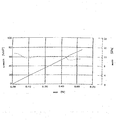
図2は、材木に対する典型的な張力負荷(実線)と導出した弾性係数(破線)を示す。張力検査の間における、時間、力、伸長率を記録し、評価ソフトが、力の値と初期断面積から連続的に計算した。 FIG. 2 shows a typical tension load on the timber (solid line) and the derived elastic modulus (dashed line). The time, force, and elongation rate during the tension test were recorded, and the evaluation software continuously calculated from the force value and the initial cross-sectional area.
含水量検査及び機械装置を用いた外部内部の光学検査の後に、未加工の材料を、断片ごとや部分ごとに、例えば有用性によってA:最高品質、B:中級品質、R:ひび割れを示す品質のように、分類するとよい。使用不可能な部分は、生産プロセスにおいて、切断されて除去される。この最初の生産段階の後に、該材木断片は上記分類に分けられる。この後、材木の接合に続く。それぞれの分類又は品質レベルにおける部品は、断片ごとに、例えばフィンガージョイントなどの接合技術によって、一続きに連結される。所定の最終の長さに達した後は、該一続きに連結した材木は、例えば8mというように、所望の長材の長さに分割される。そして、このようにして得られた該長材は、粘着又は接着を熟成するための場所に運ばれ、品質レベルごとに配置される。この手順は、全ての品質レベルについて繰り返される。そして、第2の製造段階における該製品は、あらかじめ品質ごとに分けられ、張力検査はまだされていない状態で、提供される。 After water content inspection and optical inspection inside and outside using mechanical equipment, the raw material is processed into pieces and parts, for example, A: highest quality, B: intermediate quality, R: quality showing cracks depending on usefulness It is good to classify like this. Unusable parts are cut and removed in the production process. After this initial production phase, the timber pieces are divided into the above categories. This is followed by timber joining. The parts at each classification or quality level are joined together piece by piece, for example by a joining technique such as a finger joint. After reaching the predetermined final length, the connected timber is divided into the desired length of the timber, for example 8 m. Then, the long material obtained in this way is transported to a place for aging adhesion or adhesion, and is arranged for each quality level. This procedure is repeated for all quality levels. Then, the products in the second manufacturing stage are provided in a state in which the products are divided according to quality in advance and have not been subjected to tension inspection yet.
粘着の熟成期間経過後、張力検査が製品の分類に応じた方法で行なわれる。 After the adhesive aging period has elapsed, a tension test is performed in a manner corresponding to the product classification.
ここで、以下に、図3〜7に基づいて、張力検査をどのように行なうか説明する。 Here, how the tension inspection is performed will be described below with reference to FIGS.
図3aに示すように、長材1は、断片2、3がフィンガージョイント部4によって接合され、荒く平削りされたものである。長材1は、互いに対向する位置に対になるように配置された締付け顎6によって、端域5で固定されている。ここで一対の締付け顎6は、長材1における片方の端域5に固定され、もう片方の端域5では、張力検査のため軸方向に可動となるように備えられる。
As shown in FIG. 3 a, the
図3bに示すように、長材1に対する張力検査により、最初の長さ変化△lが生じる。さらに、最終検査荷重まで張力を増加すると、図3に示すように長材1は破損する。これにより、例えば内部の裂け目などが、脆弱部7として形成される。これは予備試験では検出されずに残存したものである。上記脆弱部7は、図4a及び4bに示すように切断される。そして2つの残存断片8及び9には、切断表面に仕口10が形成される。仕口10は、再度接合するために形成されるものである。
As shown in FIG. 3 b, the first length change Δl is generated by the tension test on the
図5aに示すように、他の断片11が二つの断片8、9の間に挿入される。こうすることで、長材1は、脆弱部7を切断したにもかかわらず、再度元の長さ12に達する。次に、図5bに示すように、最終荷重を負荷した張力検査を改めて行なう。ここで検出される長さの変化△l1が、許容される分類のものであれば、長材1’は該検査を通過する。
Another
最大荷重による長さの検査は、締付け顎6の対と他方の締付け顎6の対との距離を距離Zに制限している。締付け顎を備える長材1の端域5に対しては、最大荷重による検査はされない。端域5を越すと張力は減少するからである。
The length inspection with the maximum load limits the distance between the pair of clamping
図6には、誤差検出後の、長材を製造するための3本の原木が、略平らな状態で示されている。長材における領域A、B、C及びIは、縦のひび割れ13を有し、当該領域は、長材1’に係るグレードと分けるため、図7の右手に示すように、フィンガージョイント部4を介して連結される。欠点や脆弱部が検出されていない領域D、E、F及びGは、それぞれフィンガージョイント部4によって、高品質の長材1に組み込まれる。2つの破損木片Hは、領域Iと同様に排除される。長材1及び1’は、本発明に係る張力検査に供される。
In FIG. 6, three logs for manufacturing a long material after error detection are shown in a substantially flat state. Regions A, B, C and I in the long material have
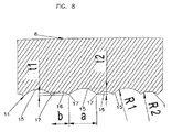
図8は、締付け顎6の断面図である。張力検査による長さの変化を測定するため長材1に対して負荷する大きな荷重に、完全に適合したものである。また、締付け顎6には、例えば、溝15及び16などの横向きの溝が、長材1の長手方向に横向きに、又は、張力の方向に設けられている。溝15及び16は、領域14から、長材1に接する範囲で、形成されており、それぞれt1、t2という異なる深さを有している。浅い方の深さt2を有する溝16は、より深い溝15に隣接し、溝15から溝16に変位する変位部17は、鋭利な角となるように形成することが好ましい。
FIG. 8 is a cross-sectional view of the clamping
溝15及び16の断面は、刻み円形であることが好ましい。そして、より深い方の溝15の断面に示される曲率半径R1は、浅い方の深さt2を備える溝16に係る半径よりも若干大きいものであることが好ましい。溝15及び16におけるそれぞれの弦の幅a及び幅bは、例えば、浅い方の溝16に係る幅bは、大きい溝15に係る幅aに対して、0.3〜0.6の範囲であることが好ましい。また、このときR1とR2は0.8〜1.5の範囲であることが好ましい。
The cross sections of the
図9から11は、請求項1に記載の方法に基づいて検査された長材1及び1’から形成された、いわゆる角材21〜23に関する図である。図9はいわゆる二重角材(Duo Beam)21を示し、図10はいわゆる三重角材(Trio Beam)22を示し、図11はいわゆる四重角材(Quattro Beam)23を示す。
FIGS. 9 to 11 are views relating to so-called
上記角材21〜23の本質的特徴は、接着接合部25によって垂直方向に接合されており、その結果、側面26は、まだら模様27を有している。長材1及び1’に係る幅28は60mm、70mm又は80mmであることが好ましい。これにより、二重角材21に係る幅29は、120mm〜160mmとなる。長材1及び1’の高さ30は200mm〜300mmであることが好ましい。特に高い耐圧容量を要する接着接合部25は、上記長材1及び1’の側面が鉛直面であって該側面が互いに接着される場合、接着より前に研磨される。
The essential features of the
本発明によれば、角材の幅29は、少なくとも長材1及び1’に係る幅28の2倍を有することになる。即ち、二重角材の場合、2倍であり、三重角材の場合、3倍であり、四重角材の場合、4倍である。
According to the present invention, the
図12には、既存の接合材31を示す。上記接合材31は、集成材である板材32から形成されている。個々の板材の高さ33は、通常3cm〜4cmである。板材32の幅34は、通常120mm〜200mmの範囲である。このような接合材31は、割高であり、大量の接着剤又は粘着材を要する。側面図は、全ての接着接合及び材木にかかる材質を簡単に示している。
FIG. 12 shows an existing
本発明によれば、図13に示すように、このような接合材の代わりに、結合角材35を提供できる。結合角材35は、例えば、3つの二重角材21を上に重ねて、それぞれを接着接合部25によって鉛直に接合することで形成される。幅36は、結合角材と同様に120mm〜200mmの範囲内であるが、例えば、三重角材22又は四重角材23を上に積み重ね、互いに接着することによって、これ以上の値となってもよい。
According to the present invention, as shown in FIG. 13, a
結合角材35の、板材32によって形成される接合材31に対する利点は、美しいまだら模様27を、その側面に見ることができるという外観だけではなく、特に、検査された長材1及び1’の全長をそれぞれ横に重ね合わせることによる、その耐圧容量にある。これは硬材から形成されると、さらに重要な特徴となる。
The advantage of the
図13に係る破線は、長材1、1’を、結合角材35の頂上部及び/又は底部に接着することができることを表している。そして、この接着により該頂上部及び/又は底部にまだら模様を持つようになり、それぞれ、板材32により形成される接合材31の下層と同様の外観となる。
The broken lines according to FIG. 13 indicate that the
角材21〜角材23及び結合角材35のそれぞれにおいて、辺材37に係る特別な強度による利点を得るためには、400mm以上の直径を有する硬材38を図14に示す切断プランに従って、切り分ければよい。例えば、約500mm〜600mmの高さ30を有する長材1、1’を製造することができる。硬材38の辺材37などにおいて、年輪幅が狭い端部39が外側になるように切断する。
In each of the
例えば、長材1、1’のような2本の長材を互いに接着して角材21を形成する場合であって、請求項1に記載の方法により、品質検査を実施する場合、特に高い耐圧容量を有する角材21を製造することができる。また、さらに辺材38により形成される角材における張力及び圧力の負荷領域は、上述したように、さらに高い強度を持ち、特に張力に対して高い強度を有する。図15に示したように、このような種類の角材21は、側面に、接着接合部の無い、まだら模様27を持つ。このような寸法の角材は、トラムバインダーとしても利用できる。
For example, in the case where two long members such as the
角材21は、上述の通り、特に低コストで製造することができる。図14に示すように、材木の残余部は極めて少なく、さらに、該製造に必要な加工工程はわずかである。
As described above, the
張力検査装置の具体例を図16から19に示す。図16から19に示すように、動力台座41は、基礎42の上に設置されている。上記動力台座41の一端は、最初の引っ張り架台43を運ぶ。架台43は、位置を固定又は固定できるように、2つの締付け顎44及び45を備える。第1の締付け顎44は、引っ張り架台43を、検査に供する長材1のための支持台46の高さに固定する。第2の締付け顎45は、上記締付け顎44の対向位置に配置される。このように第2の締付け顎は、低い方の締付け顎44とは対照的に、加圧シリンダー48のような加重装置によって、押し付けることができるようになっており、これにより長材1を押さえつけ固定する。
Specific examples of the tension inspection apparatus are shown in FIGS. As shown in FIGS. 16 to 19, the
図18に示すように、正面49は、動力台座43の長手方向から見た引っ張り架台43の正面である。中央寄せ手段50は、長材1を検査に供させるように設けられており、支持台46上に設けられた横断コンベヤー51を介して長材を動力台座41に運ぶことができる。上記横断コンベヤー51は、複数のコンベヤーが連結することにより及び/又はコンベヤーベルトにより作製することが好ましく、それぞれ隣り合うように設置される。そして、長材1の端である端域52が、締付け顎44及び45の間となるように横たえられる。
As shown in FIG. 18, the front surface 49 is the front surface of the pulling
2本の中央寄せアーム53により形成される中央寄せ手段50は、引っ張り架台43の上方に回転可能に設置されており、引っ張り架台43に対して、正確に中央位置に配置させることが可能となっている。中央寄せアーム53は、加圧シリンダー54などの調整部材によって、図19に破線で示す締付け顎44及び45上の静止位置Rから、図19に実線で示す中央位置Zに、同時に回転する。上記同時の回転は、例えば、連結歯状部材55により実現される。上記連結歯状部材55は、トルクに耐え得るように中央寄せアーム53に連結される。
The centering means 50 formed by the two centering
第二の引っ張り架台56は、上記引っ張り架台43と同じ設計であるが、動力台座41の他の端域に、向かい合うように設置される。上記第二の引っ張り架台56は、動力台座41に対して、矢印57の方向に動かすことができる。これは、二つの引っ張り架台43及び56の締付け顎44及び45によって、様々な長さの長材1を、その長さに応じて端域52において締め付けるためである。
The second pulling
動力台座41の横には、検査に供する長材1を供給するための緩衝領域58が設けられ、反対側には既に検査を受けた長材1を蓄積するための蓄積領域59が設けられている。そして、上記領域58及び59に対して長材を除去する又は運ぶ。このそれぞれの動作は、長材1の長手方向に対して行なわれる。また、検査の後、脆弱部を示した長材を、脆弱部の切除後加工工程に戻すために排出する、排出整理用弁を備えることが好ましい。
Next to the
長材1を二つの引っ張り架台43及び56上に留めて、上記長材1に対して、図中の矢印60の方向に張力を加えるために、引っ張り架台43及び56の内、少なくとも一つは、加圧装置などの手段によって、片方の引っ張り架台から離れるように動作可能にすることが好ましい。なお、上記加圧装置は本実施の形態にかかる図面には示していない。
In order to hold the
検査による負荷がかけられていない長材1と、負荷がかけられた長材1との長さの差を検出するために、引っ張り架台43及び56上にスキャナ61が搭載されている。スキャナ61は、検査による力が加えられる前と加えられている間、長材の表面62に対して所定の力により押し当てるように、長材の表面62の方向に動く。長材1の長さの変化によるスキャナ61の動きは、適切な測定装置により求められ、座標計算拠点に伝達される。
A
図に示した本実施の形態は、動力台座41は、鉄板により作られた箱形断面梁として設計していた。これは、基礎42そのものにより形成されても良いことは当然である。また、本実施の形態に係る図において、動力台座41上に設けた第二の引っ張り架台56を可動とするための誘導レールが、上記基礎42上に設置してもよいことは明らかである。
In the present embodiment shown in the figure, the
Claims (31)
上記の長さ(12)以下に調製された各長材(1、1’)であって、適切かつ完全に接合された長材(1、1’)に対して、上記長材のそれぞれの端(5)を押さえて、張力を与える工程と、
その後、欠陥のない長材が破損する負荷を超えることのない閾値まで張力を増加する工程と、
上記の処理に伴い増加する長材の長さの変化(△l)を少なくとも一部分あるいはその長材(1、1’)の全長にわたって測定する工程と、
上記変化を、上記長材(1、1’)の利用において、又は、その他のさらなる処理において、品質基準として使用する工程とを含むことを特徴とする方法。 In a method of guaranteeing the quality of structural timber, in particular a continuous material (1, 1 ') having a predetermined minimum length (12), continuously produced and appropriately finger jointed,
Each of the long members (1, 1 ') prepared to be equal to or shorter than the length (12), and appropriately and completely joined to each of the long members (1, 1') Pressing the end (5) and applying tension;
Thereafter, increasing the tension to a threshold that does not exceed the load at which the defect-free long material breaks; and
Measuring the change in length (Δl) of the long material that increases with the above-described treatment over at least a part or the entire length of the long material (1, 1 ′);
Using the change as a quality standard in the use of the long material (1, 1 ') or in other further processing.
許容外の長さの変化又は長材の脆弱部の原因となる長材(1)に係る脆弱部(7)を、それぞれ切り出し、
脆弱部を除去した残余部分(8、9)を、フィンガージョイント接合によって新たな長材に集成し、
適宜、更に長い長材断片(11)を加えた上で、
新たな長材(1’)を製造し、再度請求項1に記載の方法に供することを特徴とする請求項1から5のいずれか1項に記載の方法。 If the change in length of the long material (1) increases beyond a predetermined allowable range by applying a predetermined tension, the long material (1) is removed from the production process;
Cut out the fragile parts (7) according to the long material (1) that cause the unacceptable length change or the fragile part of the long material,
The remaining parts (8, 9) from which the fragile parts have been removed are assembled into a new long material by finger joint joining,
If appropriate, after adding a longer long piece (11),
The method according to claim 1, wherein a new long material (1 ′) is produced and again subjected to the method according to claim 1.
上記締付け顎(6)の面には溝(15、16)が設けられており、
上記溝(15、16)は、その断面形状が弓形、好ましくは、円弧状の弓形であり、荷重方向に横断するように設けられていることを特徴とする装置。 An apparatus for executing the method according to any one of claims 1 to 9, wherein the apparatus is a tension inspection facility that applies tension to a long material, and includes a clamping jaw (6) attached to the long material,
Grooves (15, 16) are provided on the surface of the clamping jaw (6),
The groove (15, 16) has an arcuate cross-sectional shape, preferably an arcuate arcuate shape, and is provided so as to cross the load direction.
検査する長材片(1)における最大の長さに対応する長さを有する検査用台座(41)、特に動力台座と、
上記検査用台座(41)の端域に設けられ、好ましくは固定して設けられる第一の引っ張り架台(43)と、
上記検査用台座(41)に沿って可動で、検査する長材片(1)における長さに対して調整可能な引っ張り架台(56)と、
上記引っ張り架台(43、56)の両方に設けられ、検査位置に運ばれた長材片(1)を、上方及び下方から掴んで固定する締付け顎(44、45)と、
上記引っ張り架台(43、56)によって固定した長材片(1)に、力を加える装置と、
検査用台座(41)の横に位置し長材片(1)の緩衝領域(57)から、検査用台座(41)に、そして、上記検査用台座(41)に対して上記緩衝領域(57)の反対側に位置し検査後の長材片(1)を蓄える蓄積領域(58)に、長材片(1)を運ぶ横断コンベヤー(51)と、
締付け顎(44、45)間の検査位置に運ばれた長材片(1)を中央に寄せる中央寄せ手段(50)とを備えることを特徴とする装置。 An apparatus for performing the method according to any one of claims 1 to 9, particularly for hardwood,
An inspection pedestal (41) having a length corresponding to the maximum length of the long piece of material (1) to be inspected, in particular a power pedestal;
A first pulling base (43) provided in an end region of the inspection base (41), preferably fixed;
A pulling base (56) movable along the inspection base (41) and adjustable with respect to the length of the long piece (1) to be inspected;
Fastening jaws (44, 45) that are provided on both of the pulling bases (43, 56) and hold and fix the long piece (1) carried to the inspection position from above and below;
A device for applying force to the long piece (1) fixed by the pulling base (43, 56);
Next to the inspection pedestal (41), from the buffer region (57) of the long piece (1) to the inspection pedestal (41) and to the inspection pedestal (41), the buffer region (57 A crossing conveyor (51) for transporting the long piece of material (1) to a storage area (58) for storing the long piece of material (1) after inspection,
A centering means (50) for bringing the long piece (1) conveyed to the inspection position between the clamping jaws (44, 45) to the center.
Applications Claiming Priority (4)
| Application Number | Priority Date | Filing Date | Title |
|---|---|---|---|
| AT16992003A AT412674B (en) | 2003-10-27 | 2003-10-27 | METHOD FOR QUALITY ASSURANCE OF LONGWOOD |
| AT10542004A AT413764B (en) | 2004-06-22 | 2004-06-22 | Quality assurance procedure for mass produced, construction grade, adhesive jointed spliced timber lengths, includes tensile testing to a set point below the breaking point of similar fault-free timber |
| AT10552004A AT500614B1 (en) | 2004-06-22 | 2004-06-22 | Quality assurance procedure for mass produced, construction grade, adhesive jointed spliced timber lengths, includes tensile testing to a set point below the breaking point of similar fault-free timber |
| PCT/AT2004/000362 WO2005040766A1 (en) | 2003-10-27 | 2004-10-21 | Method for quality assurance of timber |
Publications (1)
| Publication Number | Publication Date |
|---|---|
| JP2007509357A true JP2007509357A (en) | 2007-04-12 |
Family
ID=34527213
Family Applications (1)
| Application Number | Title | Priority Date | Filing Date |
|---|---|---|---|
| JP2006536995A Pending JP2007509357A (en) | 2003-10-27 | 2004-10-21 | Quality assurance method for long materials |
Country Status (5)
| Country | Link |
|---|---|
| US (1) | US7418874B2 (en) |
| EP (1) | EP1678479B1 (en) |
| JP (1) | JP2007509357A (en) |
| CA (1) | CA2542969A1 (en) |
| WO (1) | WO2005040766A1 (en) |
Cited By (1)
| Publication number | Priority date | Publication date | Assignee | Title |
|---|---|---|---|---|
| JP2011242320A (en) * | 2010-05-20 | 2011-12-01 | Naigai Kogyo Co Ltd | Glulam strength measurement method |
Families Citing this family (15)
| Publication number | Priority date | Publication date | Assignee | Title |
|---|---|---|---|---|
| AT8982U1 (en) * | 2005-05-02 | 2007-03-15 | Holzindustrie Leitinger Ges M | BAR TIMBER OF WOOD |
| CA2631154A1 (en) * | 2005-11-28 | 2007-05-31 | Navy Island Plywood, Inc. | Method of rating wood product quality |
| US7467904B1 (en) * | 2006-12-04 | 2008-12-23 | David Joseph Wager | Tree-ring chronology pens, pencils, key chains, and other commonly used articles |
| US20080283151A1 (en) * | 2007-05-15 | 2008-11-20 | Weyerhaeuser Co. | Warp Stable Wood Product And Methods For Detecting The Same |
| AT506264B1 (en) * | 2008-01-11 | 2010-08-15 | Springer Maschinenfabrik Ag | METHOD FOR PROCESSING LIME-GALKY LONG-TERM PIECE GOODS |
| EP2335043B1 (en) * | 2008-09-24 | 2014-12-17 | MICROTEC S.r.l. | Device and method for proof loading wooden boards in traction |
| ES2338743B1 (en) * | 2009-11-17 | 2011-06-10 | Universidad De Valladolid | "WOOD BEAMS DUO AND TRIO REINFORCED THROUGH GLOSSY BANDS". |
| AT11958U1 (en) * | 2010-09-07 | 2011-08-15 | Hans-Peter Ing Leitinger | PROCESS FOR PROCESSING RAW ROUNDWOOD AND WEDGE-LINKED WOOD COMPOSITE PRODUCTS |
| ITBZ20110001A1 (en) * | 2011-01-17 | 2012-07-18 | Microtec Srl | METHOD FOR THE REALIZATION OF SHAPED PROFILES STARTING FROM WOODEN TABLES |
| UA120419C2 (en) | 2013-08-27 | 2019-12-10 | Велінге Інновейшн Аб | A method for producing a lamella core |
| US9958428B2 (en) * | 2014-10-09 | 2018-05-01 | Haskan, Llc | Scanning system for wood |
| CN104458423B (en) * | 2014-12-24 | 2017-03-08 | 黑龙江省木材科学研究所 | 50 tons of closed loop measurement and control timber tensile test apparatus |
| WO2019079728A1 (en) * | 2017-10-20 | 2019-04-25 | Mitek Holdings, Inc. | Automated lumber cutting and delivery system |
| CN112955612B (en) | 2018-08-21 | 2023-07-25 | 约翰·大维·日头 | Barrier-capable barrier architecture apparatus and methods of making and using the same |
| US11787081B1 (en) * | 2023-05-30 | 2023-10-17 | Frametec Alpha IP LLC | Wooden truss manufacturing system and method |
Citations (9)
| Publication number | Priority date | Publication date | Assignee | Title |
|---|---|---|---|---|
| JPS61129148A (en) * | 1984-11-22 | 1986-06-17 | アルファ・ワッセルマン・エッセ・ピ・ア | Optical resolution of racemic mixture of alpha-naphthylpropionic acid |
| JPH0247533A (en) * | 1988-08-08 | 1990-02-16 | Misawa Homes Co Ltd | Non-destructive tester |
| JPH0378240A (en) * | 1989-08-21 | 1991-04-03 | Mitsubishi Electric Corp | Semiconductor integrated circuit device |
| JPH09174518A (en) * | 1995-10-25 | 1997-07-08 | Shinei Gohan Kogyo Kk | Glued laminated wood of veneer laminated material and its manufacture |
| JPH11129220A (en) * | 1997-11-04 | 1999-05-18 | Ichijyo Home Building Co Ltd | Laminated lumber |
| JPH11156817A (en) * | 1997-12-01 | 1999-06-15 | Nakano Komuten:Kk | Building wood |
| JP2002122525A (en) * | 2000-10-16 | 2002-04-26 | Misawa Homes Co Ltd | Grading machine and grade identification method of wood for laminated lumber using the same |
| JP2002214098A (en) * | 2001-01-17 | 2002-07-31 | Kawasaki Kiko Co Ltd | Grading machine for wood |
| JP2002331505A (en) * | 2001-05-08 | 2002-11-19 | Tenri Shuseizai Kk | Method and system for timber-conversion of lamina for laminated timber |
Family Cites Families (18)
| Publication number | Priority date | Publication date | Assignee | Title |
|---|---|---|---|---|
| US3714820A (en) | 1971-10-01 | 1973-02-06 | Univ Washington | Combined tensile e measurement and proof loading of lumber |
| US3919884A (en) * | 1974-04-17 | 1975-11-18 | Us Air Force | Horizontal loading fixture for sustained load testing |
| DE7608950U1 (en) | 1976-03-23 | 1976-09-02 | Ostbayerische Holzbau Gmbh & Co Kg, 8353 Osterhofen | RUSTIC TABLE |
| US4321834A (en) * | 1979-05-07 | 1982-03-30 | Oliver George A | Mechanical stress grading of timber |
| US4570913A (en) * | 1984-01-11 | 1986-02-18 | Production Equipment & Engineering Co. | Clamping apparatus for truss manufacturing equipment |
| DE3412675A1 (en) * | 1984-04-04 | 1985-10-17 | Konrad 8938 Buchloe Marek | Method and devices for realistic measurement of the tearing strength of paper |
| US4941357A (en) * | 1988-12-23 | 1990-07-17 | Weyerhaeuser Company | Method for estimating the strength of wood |
| DE8900698U1 (en) | 1989-01-23 | 1989-04-20 | Schacht, Peter, 8222 Ruhpolding, De | |
| DE4012444A1 (en) * | 1990-04-19 | 1991-10-24 | Stein Herbert Textechno | Clamping device for high strength filament or ribbon material |
| DE4140349A1 (en) * | 1991-04-12 | 1992-10-15 | Oberspree Habelwerk Gmbh | Clamp for tubular or pipe-shaped bodies for tensile strain testing - has spring, wedge-shaped tongues compressed by applying outer clamp casing with inner conical surface, pin inside clamped tube |
| US5237870A (en) * | 1991-09-20 | 1993-08-24 | Metriguard Inc. | Stress wave method and apparatus for estimating the structural quality of finger joints |
| US5679190A (en) * | 1992-02-03 | 1997-10-21 | Minnesota Mining And Manufacturing Company | Method of making nonwoven sheet materials, tapes |
| US5585732A (en) * | 1995-06-07 | 1996-12-17 | Mississippi State University | Detector for heterogeneous materials |
| US5679191A (en) * | 1995-07-20 | 1997-10-21 | Robinson; T. Lee | Method of fabricating trailer length platform truck flooring |
| US6122877A (en) * | 1997-05-30 | 2000-09-26 | Andersen Corporation | Fiber-polymeric composite siding unit and method of manufacture |
| US6231947B1 (en) * | 1999-12-29 | 2001-05-15 | David A. Hill | Method of forming wood-veneered product |
| JP3502026B2 (en) | 2000-08-24 | 2004-03-02 | 山佐木材株式会社 | Glued lumber manufacturing method |
| DE202004001914U1 (en) | 2004-02-09 | 2004-04-08 | Moser, Karl-Heinz | Wooden beam for supporting constructions consists of laminated wood beam with veneer material applied to one part of surface, and preferably applied where beam remains visible after installation |
-
2004
- 2004-10-21 CA CA002542969A patent/CA2542969A1/en not_active Abandoned
- 2004-10-21 EP EP04761077.9A patent/EP1678479B1/en active Active
- 2004-10-21 WO PCT/AT2004/000362 patent/WO2005040766A1/en active Application Filing
- 2004-10-21 JP JP2006536995A patent/JP2007509357A/en active Pending
-
2006
- 2006-04-19 US US11/406,368 patent/US7418874B2/en not_active Expired - Fee Related
Patent Citations (9)
| Publication number | Priority date | Publication date | Assignee | Title |
|---|---|---|---|---|
| JPS61129148A (en) * | 1984-11-22 | 1986-06-17 | アルファ・ワッセルマン・エッセ・ピ・ア | Optical resolution of racemic mixture of alpha-naphthylpropionic acid |
| JPH0247533A (en) * | 1988-08-08 | 1990-02-16 | Misawa Homes Co Ltd | Non-destructive tester |
| JPH0378240A (en) * | 1989-08-21 | 1991-04-03 | Mitsubishi Electric Corp | Semiconductor integrated circuit device |
| JPH09174518A (en) * | 1995-10-25 | 1997-07-08 | Shinei Gohan Kogyo Kk | Glued laminated wood of veneer laminated material and its manufacture |
| JPH11129220A (en) * | 1997-11-04 | 1999-05-18 | Ichijyo Home Building Co Ltd | Laminated lumber |
| JPH11156817A (en) * | 1997-12-01 | 1999-06-15 | Nakano Komuten:Kk | Building wood |
| JP2002122525A (en) * | 2000-10-16 | 2002-04-26 | Misawa Homes Co Ltd | Grading machine and grade identification method of wood for laminated lumber using the same |
| JP2002214098A (en) * | 2001-01-17 | 2002-07-31 | Kawasaki Kiko Co Ltd | Grading machine for wood |
| JP2002331505A (en) * | 2001-05-08 | 2002-11-19 | Tenri Shuseizai Kk | Method and system for timber-conversion of lamina for laminated timber |
Cited By (1)
| Publication number | Priority date | Publication date | Assignee | Title |
|---|---|---|---|---|
| JP2011242320A (en) * | 2010-05-20 | 2011-12-01 | Naigai Kogyo Co Ltd | Glulam strength measurement method |
Also Published As
| Publication number | Publication date |
|---|---|
| EP1678479A1 (en) | 2006-07-12 |
| US7418874B2 (en) | 2008-09-02 |
| CA2542969A1 (en) | 2005-06-06 |
| EP1678479B1 (en) | 2017-07-05 |
| US20060259252A1 (en) | 2006-11-16 |
| WO2005040766A1 (en) | 2005-05-06 |
Similar Documents
| Publication | Publication Date | Title |
|---|---|---|
| US7418874B2 (en) | Method for quality assurance of long timber | |
| US5679191A (en) | Method of fabricating trailer length platform truck flooring | |
| AU769197B2 (en) | Method for determining warp potential in wood | |
| JP2011017565A (en) | Optical quality evaluation method of wood | |
| CA2407156C (en) | Method of evaluating logs to predict properties of lumber or veneer produced from the logs | |
| US6293152B1 (en) | Method for determining twist potential in wood | |
| Guntekin et al. | Prediction of bending properties for turkish red Pine (Pinus brutia Ten.) lumber using stress wave method | |
| SI22020A (en) | Procedure and device for testing timber structural elements | |
| JP3399497B2 (en) | Glued laminate manufacturing method and apparatus | |
| AT412674B (en) | METHOD FOR QUALITY ASSURANCE OF LONGWOOD | |
| Fuller et al. | Nondestructive evaluation of honeycomb and surface checks in red oak lumber | |
| Dündar et al. | European wood NDT & NDE research and practical applications | |
| Beall | Subsurface sensing of properties and defects in wood and wood products | |
| CN104596924A (en) | Method for rapidly checking internal bonding strength of artificial board and special clamps | |
| US8394216B1 (en) | System and method for detecting features on a laminated veneer lumber billet | |
| RU2482468C1 (en) | Method of carrying out examination of inner side of structure sawing logs | |
| Kimmel et al. | Red maple and yellow-poplar LVL from ultrasonically rated veneer | |
| DeVallance | Influence of veneer roughness, lathe check, and annual ring characteristics on glue-bond performance of Douglas-fir plywood | |
| Mohammadabadi et al. | Wood defect detection using low acoustic impedance-based PZT transducers | |
| RU2006118353A (en) | METHOD FOR MAKING QUALITY OF LENGTH WOOD | |
| Rescalvo et al. | EVALUATION OF THE MECHANICAL BEHAVIOUR OF POPLAR SPECIMENS WITH AND WITHOUT FINGERS SUBJECTED TO TENSILE STRESS BY MEANS OF ACOUSTIC EMISSION AND DIC | |
| AU2020295065A1 (en) | Engineered timber panel for structural use and method of formation thereof | |
| Čukman et al. | COMPARISON OF MODULY OF ELASTICITY OBTAINED BY NON-DESTRUCTIVE AND DESTRUCTIVE TESTS OF TIMBER SAMPLES | |
| Bucur | Acoustic methods as a nondestructive tool for wood quality assessment | |
| Standard | Construction and Industrial Plywood |
Legal Events
| Date | Code | Title | Description |
|---|---|---|---|
| A621 | Written request for application examination |
Free format text: JAPANESE INTERMEDIATE CODE: A621 Effective date: 20070920 |
|
| A977 | Report on retrieval |
Free format text: JAPANESE INTERMEDIATE CODE: A971007 Effective date: 20091112 |
|
| A131 | Notification of reasons for refusal |
Free format text: JAPANESE INTERMEDIATE CODE: A131 Effective date: 20091124 |
|
| A601 | Written request for extension of time |
Free format text: JAPANESE INTERMEDIATE CODE: A601 Effective date: 20100224 |
|
| A602 | Written permission of extension of time |
Free format text: JAPANESE INTERMEDIATE CODE: A602 Effective date: 20100303 |
|
| A521 | Request for written amendment filed |
Free format text: JAPANESE INTERMEDIATE CODE: A523 Effective date: 20100520 |
|
| A131 | Notification of reasons for refusal |
Free format text: JAPANESE INTERMEDIATE CODE: A131 Effective date: 20100817 |
|
| A601 | Written request for extension of time |
Free format text: JAPANESE INTERMEDIATE CODE: A601 Effective date: 20101109 |
|
| A602 | Written permission of extension of time |
Free format text: JAPANESE INTERMEDIATE CODE: A602 Effective date: 20101116 |
|
| A02 | Decision of refusal |
Free format text: JAPANESE INTERMEDIATE CODE: A02 Effective date: 20110426 |