JP2007501639A - A liquid-filled package that can be used to make beverages - Google Patents
A liquid-filled package that can be used to make beverages Download PDFInfo
- Publication number
- JP2007501639A JP2007501639A JP2006521796A JP2006521796A JP2007501639A JP 2007501639 A JP2007501639 A JP 2007501639A JP 2006521796 A JP2006521796 A JP 2006521796A JP 2006521796 A JP2006521796 A JP 2006521796A JP 2007501639 A JP2007501639 A JP 2007501639A
- Authority
- JP
- Japan
- Prior art keywords
- package
- liquid
- gas
- package according
- chamber
- Prior art date
- Legal status (The legal status is an assumption and is not a legal conclusion. Google has not performed a legal analysis and makes no representation as to the accuracy of the status listed.)
- Pending
Links
Images


Classifications
-
- A—HUMAN NECESSITIES
- A47—FURNITURE; DOMESTIC ARTICLES OR APPLIANCES; COFFEE MILLS; SPICE MILLS; SUCTION CLEANERS IN GENERAL
- A47J—KITCHEN EQUIPMENT; COFFEE MILLS; SPICE MILLS; APPARATUS FOR MAKING BEVERAGES
- A47J43/00—Implements for preparing or holding food, not provided for in other groups of this subclass
- A47J43/27—Implements for preparing or holding food, not provided for in other groups of this subclass for mixing drinks; Hand-held shakers
-
- B—PERFORMING OPERATIONS; TRANSPORTING
- B01—PHYSICAL OR CHEMICAL PROCESSES OR APPARATUS IN GENERAL
- B01F—MIXING, e.g. DISSOLVING, EMULSIFYING OR DISPERSING
- B01F31/00—Mixers with shaking, oscillating, or vibrating mechanisms
- B01F31/55—Mixers with shaking, oscillating, or vibrating mechanisms the materials to be mixed being contained in a flexible bag submitted to periodical deformation
-
- B—PERFORMING OPERATIONS; TRANSPORTING
- B01—PHYSICAL OR CHEMICAL PROCESSES OR APPARATUS IN GENERAL
- B01F—MIXING, e.g. DISSOLVING, EMULSIFYING OR DISPERSING
- B01F23/00—Mixing according to the phases to be mixed, e.g. dispersing or emulsifying
- B01F23/20—Mixing gases with liquids
- B01F23/23—Mixing gases with liquids by introducing gases into liquid media, e.g. for producing aerated liquids
- B01F23/235—Mixing gases with liquids by introducing gases into liquid media, e.g. for producing aerated liquids for making foam
-
- B—PERFORMING OPERATIONS; TRANSPORTING
- B01—PHYSICAL OR CHEMICAL PROCESSES OR APPARATUS IN GENERAL
- B01F—MIXING, e.g. DISSOLVING, EMULSIFYING OR DISPERSING
- B01F25/00—Flow mixers; Mixers for falling materials, e.g. solid particles
- B01F25/40—Static mixers
- B01F25/45—Mixers in which the materials to be mixed are pressed together through orifices or interstitial spaces, e.g. between beads
- B01F25/451—Mixers in which the materials to be mixed are pressed together through orifices or interstitial spaces, e.g. between beads characterised by means for moving the materials to be mixed or the mixture
- B01F25/4512—Mixers in which the materials to be mixed are pressed together through orifices or interstitial spaces, e.g. between beads characterised by means for moving the materials to be mixed or the mixture with reciprocating pistons
-
- B—PERFORMING OPERATIONS; TRANSPORTING
- B01—PHYSICAL OR CHEMICAL PROCESSES OR APPARATUS IN GENERAL
- B01F—MIXING, e.g. DISSOLVING, EMULSIFYING OR DISPERSING
- B01F25/00—Flow mixers; Mixers for falling materials, e.g. solid particles
- B01F25/40—Static mixers
- B01F25/45—Mixers in which the materials to be mixed are pressed together through orifices or interstitial spaces, e.g. between beads
- B01F25/452—Mixers in which the materials to be mixed are pressed together through orifices or interstitial spaces, e.g. between beads characterised by elements provided with orifices or interstitial spaces
- B01F25/4521—Mixers in which the materials to be mixed are pressed together through orifices or interstitial spaces, e.g. between beads characterised by elements provided with orifices or interstitial spaces the components being pressed through orifices in elements, e.g. flat plates or cylinders, which obstruct the whole diameter of the tube
- B01F25/45211—Mixers in which the materials to be mixed are pressed together through orifices or interstitial spaces, e.g. between beads characterised by elements provided with orifices or interstitial spaces the components being pressed through orifices in elements, e.g. flat plates or cylinders, which obstruct the whole diameter of the tube the elements being cylinders or cones which obstruct the whole diameter of the tube, the flow changing from axial in radial and again in axial
-
- B—PERFORMING OPERATIONS; TRANSPORTING
- B01—PHYSICAL OR CHEMICAL PROCESSES OR APPARATUS IN GENERAL
- B01F—MIXING, e.g. DISSOLVING, EMULSIFYING OR DISPERSING
- B01F25/00—Flow mixers; Mixers for falling materials, e.g. solid particles
- B01F25/40—Static mixers
- B01F25/45—Mixers in which the materials to be mixed are pressed together through orifices or interstitial spaces, e.g. between beads
- B01F25/452—Mixers in which the materials to be mixed are pressed together through orifices or interstitial spaces, e.g. between beads characterised by elements provided with orifices or interstitial spaces
- B01F25/4523—Mixers in which the materials to be mixed are pressed together through orifices or interstitial spaces, e.g. between beads characterised by elements provided with orifices or interstitial spaces the components being pressed through sieves, screens or meshes which obstruct the whole diameter of the tube
-
- B—PERFORMING OPERATIONS; TRANSPORTING
- B65—CONVEYING; PACKING; STORING; HANDLING THIN OR FILAMENTARY MATERIAL
- B65D—CONTAINERS FOR STORAGE OR TRANSPORT OF ARTICLES OR MATERIALS, e.g. BAGS, BARRELS, BOTTLES, BOXES, CANS, CARTONS, CRATES, DRUMS, JARS, TANKS, HOPPERS, FORWARDING CONTAINERS; ACCESSORIES, CLOSURES, OR FITTINGS THEREFOR; PACKAGING ELEMENTS; PACKAGES
- B65D85/00—Containers, packaging elements or packages, specially adapted for particular articles or materials
- B65D85/70—Containers, packaging elements or packages, specially adapted for particular articles or materials for materials not otherwise provided for
- B65D85/72—Containers, packaging elements or packages, specially adapted for particular articles or materials for materials not otherwise provided for for edible or potable liquids, semiliquids, or plastic or pasty materials
- B65D85/73—Containers, packaging elements or packages, specially adapted for particular articles or materials for materials not otherwise provided for for edible or potable liquids, semiliquids, or plastic or pasty materials with means specially adapted for effervescing the liquids, e.g. for forming bubbles or beer head
Abstract
Description
本発明は、ガスと、飲料を作ることができる少なくともある程度泡立ち可能な液体とを含むパッケージに関する。 The present invention relates to a package comprising a gas and at least some foamable liquid capable of making a beverage.
本発明はまた、ガス及び少なくともある程度泡立ち可能な液体を含むパッケージ内に泡を得るための方法であって、この泡によって飲料を作ることができる一方、液体及びガスをパッケージ内で移動させることを含む方法に関する。 The present invention is also a method for obtaining foam in a package comprising a gas and at least some foamable liquid, wherein the foam can be used to make a beverage while liquid and gas are moved within the package. Relates to the method of including.
加えて、本発明は、泡層を有して、直ぐに消費されるのに適するコーヒーを淹れる方法に関する。 In addition, the present invention relates to a method for brewing coffee that has a foam layer and is suitable for immediate consumption.
そのような装置は、ドイツ特許第DE4332387号から既知である。これには、液体抽出物を内部に含む気密ホルダが記載されている。ホルダの容積の一部分が空気によって占められている。パッケージを開く前に、ホルダを振ることができ、空気及び液体が混合し、それにより、泡がホルダ内に形成される。混合中、ガスは、言わば液体に取り込まれ、気泡の形成をもたらす。気泡の形成が頻繁に起きると、泡が形成される。ホルダを開いてから、その泡を飲むか、カップなどに入れることができる。 Such a device is known from DE 43 32 387. This describes an airtight holder containing a liquid extract inside. A portion of the volume of the holder is occupied by air. Prior to opening the package, the holder can be shaken so that air and liquid mix, thereby forming a bubble in the holder. During mixing, the gas is soaked into the liquid, resulting in the formation of bubbles. If bubble formation occurs frequently, bubbles are formed. After opening the holder, you can drink the foam or put it in a cup.
そのようなパッケージの欠点は、振ることが比較的荒々しい動作を必要とすることである。人によっては、これらの動作を行うことが不快である。十分な泡立ちを生じさせるために、時にはパッケージを非常に激しく振らなければならない。これは空間も必要とするが、既知のパッケージのユーザはそのような空間を必ずしも得ることができない。 The disadvantage of such a package is that shaking requires a relatively rough operation. Some people are uncomfortable performing these actions. Sometimes the package must be shaken very vigorously to produce sufficient foaming. This also requires space, but users of known packages cannot always get such space.
本発明の目的は、上記欠点の少なくとも1つに対処することである。 The object of the present invention is to address at least one of the above drawbacks.
この目的は、本発明によるパッケージであって、パッケージ内でガス及び液体の移動を生じさせ、それにより、パッケージ内で泡立ちが起きるようにすることができる手動操作手段を備えることを特徴とするパッケージにより達成される。液体及びガスを移動させる手動操作手段が存在することにより、パッケージを前後に激しく振る必要がもはやなくなる。また、使用時に、振る動きを実行するための追加空間が必要なくなる。 This object is a package according to the invention, characterized in that it comprises manual operating means that can cause gas and liquid movement in the package and thereby cause foaming in the package. Is achieved. With the presence of manual operating means for moving liquids and gases, there is no longer a need to shake the package vigorously back and forth. In addition, no additional space is required to perform the shaking motion when in use.
本明細書では、液体及び/又はガスは、時には包括的用語、すなわち流体としても表現される。 In the present specification, liquid and / or gas is sometimes also expressed as a generic term, ie fluid.
本発明によるパッケージの特別な実施形態は、その手段が、液体及びガス用のパッケージ空間を、少なくとも形状に関して手動で変化させるように構成されていることを特徴とする。したがって、非常に簡単なやり方で、ガス及び液体がパッケージ内で移動させられる。さらに、振る動きに比べて、パッケージは、少なくともほぼ一箇所に静止した状態に保持されることができ、これに伴い、あまり荒々しくなく泡立たせることができる。 A special embodiment of the package according to the invention is characterized in that the means are arranged to manually change the package space for liquids and gases at least in terms of shape. Thus, gas and liquid are moved within the package in a very simple manner. Furthermore, the package can be held stationary at least approximately in one place as compared to the shaking movement, and as a result, it can be foamed without being too rough.
好ましくは、その手段は、パッケージの少なくとも一部分を形成する、可撓性を有するように構成された材料を有すると考えられる。可撓性材料を押し合わせるか、へこませるか、又は折り畳むことができ、それにより、液体及びガスの少なくとも一部分、実際にはパッケージの、押し合わせるか、へこませるか、又は折り畳んだ容積部分内に存在した部分がパッケージ内で移動し、それにより、パッケージ内で泡立ちが起きることができる。 Preferably, the means will comprise a material configured to be flexible that forms at least a portion of the package. The flexible material can be pressed, dented or folded, so that at least a portion of the liquid and gas, in fact, the package is pressed, dented or folded The part that was present inside moves in the package, so that foaming can occur in the package.
特に、その手段はまた、液体及び/又はガスが行き来することができる少なくとも2つの相互接続されたチャンバを有すると考えられる。この場合、液体及び/又はガスは、一方のチャンバから他方のチャンバへ、また、任意選択で、その逆に移動することができる。これはたとえば、最初に一方のチャンバの容積を減少させ、それにより、液体及びガスを他方のチャンバに流すことによって行うことができる。次に、この他方のチャンバの容積を減少させ、それにより、液体及びガスを再び一方のチャンバに戻すことができる。このサイクルを何度も繰り返し、それにより、多くの泡立ちを生じることができ、また可能ならば、液体及びガスが完全に泡に変わることができる。 In particular, the means is also considered to have at least two interconnected chambers through which liquids and / or gases can come and go. In this case, the liquid and / or gas can move from one chamber to the other and optionally vice versa. This can be done, for example, by first reducing the volume of one chamber and thereby flowing liquid and gas into the other chamber. The volume of this other chamber can then be reduced so that liquid and gas can be returned to one chamber again. This cycle can be repeated many times, thereby producing many bubbles and, if possible, the liquid and gas can be completely turned into bubbles.
特に、その手段は、流体流妨害部を有すると考えられる。流体流を妨害することにより、ガス及び液体がよりうまく混合され、それにより、泡立ちがより容易に行われる。この流体流妨害部は、少なくとも2つのチャンバ間に位置する少なくとも1つのチャネル、絞り又はグリッドを有することができる。 In particular, the means is considered to have a fluid flow obstruction. By interfering with the fluid flow, the gas and liquid are better mixed so that foaming is easier. The fluid flow obstruction can have at least one channel, restriction or grid located between at least two chambers.
流体流妨害部はまた、流体流内に乱れを発生するための乱流手段を有することができる。その結果、ガス及び液体の混合が単位容積当たり高効率に行われ、このことは泡の形成に有益である。乱流手段は、その位置に、流体流を分解する小さい障害物を有することができる。乱流手段はまた、たとえば、流体が流れるチャネルの拡幅部を有する。 The fluid flow obstruction can also have turbulence means for generating turbulence in the fluid flow. As a result, gas and liquid mixing is performed with high efficiency per unit volume, which is beneficial for foam formation. The turbulence means may have a small obstacle at its location that breaks down the fluid flow. The turbulence means also has, for example, a channel widening section through which the fluid flows.
好ましくは、パッケージの少なくとも一部分が透明であるように構成されると考えられる。これにより、どの程度まで泡立ちが行われたかをユーザが観察することができるという利点が得られる。 Preferably, it is contemplated that at least a portion of the package is configured to be transparent. Thereby, the advantage that a user can observe how much foaming was performed is acquired.
次に、図面を参照しながら本発明を説明する。 Next, the present invention will be described with reference to the drawings.
図面において、同一部分には同一の参照番号が付けられている。 In the drawings, the same reference numerals denote the same parts.
本発明によるパッケージ1の各実施形態は、ガス(図示せず)及び少なくともある程度泡立ち可能な液体2を含むパッケージを有する。この液体で飲料を作ることができる。パッケージには、パッケージ1内でガス及び液体2の移動を生じさせ、それにより、パッケージ1内で泡立ちが起きるようにすることができる手動操作手段が設けられている。本明細書に記載する本発明によるパッケージの実施形態の各々が密閉パッケージを有することは、当業者には明らかであろう。特に、手動操作手段は、液体2及びガス用のパッケージ空間3を、少なくとも形状に関して手動で変化させるように構成されている。手動操作手段は、パッケージ1の少なくとも一部分を形成する、可撓性を有するように構成された材料7を有することが可能である。
Each embodiment of the
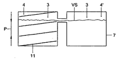
図1aの実施形態では、手動操作手段は、少なくとも2つの相互接続チャンバ4、4’を有し、その間を液体2及びガスが移動可能であると考えられる。手動操作手段は、流体流妨害部も有する。流体流妨害部はたとえば、少なくとも2つのチャンバ4、4’間に位置するチャネル5(図1a〜図1cを参照)か、絞り又はグリッド6(図5を参照)を有することができる。図1に示された実施形態では、チャンバ4、4’は、比較的剛直な部品を有する立ち上がり壁8を有する。上壁9及び下壁10が、可撓性の、且つ本例では弾性的でもある材料から製造されており、押し合わせられることができる。本例によれば、立ち上がり壁8は、可撓性の上壁9及び下壁10と一緒に曲がることはほとんどない。図1cに矢印Pで表されているように、上壁9及び下壁10を押し合わせるとき、チャンバ4の容積が減少する。図1cに示されているように、チャンバ4’の容積が増加するであろう。この時、液体2及びガスの両方がチャンバ4からチャネル5を経てチャンバ4’に流れるであろう。可撓性材料が弾性的でもあるように構成されている一実施形態では、押し合わせ力が取り除かれると、チャンバ4の容積が再び増加し、任意選択で発生する吸引効果により、液体及びガスが再びチャンバ4’からチャンバ4に戻ることができる。チャンバ4の容積の増加時には、チャンバ4’の容積が再び減少するであろう。チャンバ4及びチャンバ4’を交互に押し合わせ、それにより、流体がこれらのチャンバ間を行き来し、液体及びガスが混ざる結果として泡立ちが起きるようにすることも可能である。チャンバ4及び4’の寸法に対するチャネル5の絞りの直径により、液体及びガスの両方を含む流体は、チャンバ4からチャンバ4’へ、且つその逆に自由に流れることができない。流体は、チャネル5を経て流れるように押し進められる。流体流がチャンバ4からチャンバ4’の方向に、又はその逆に流れるときに出会う絞り、及び流体流がチャネル5からチャンバ4’又はチャンバ4のいずれかに流れ込むときに経験する拡幅化により、流体流の乱れが発生する。その結果、ガス及び液体が互いに混合され、泡立ちが起きる。
In the embodiment of FIG. 1a, the manual operating means has at least two
図2では、チャンバ4内にばね11が設けられている。図2に示されているような例では、チャンバ4の立ち上がり壁8が可撓性材料から製造される。上壁9及び下壁10は、比較的剛直な材料から製造されることができる。この変更例では、チャネル5を経てチャンバ4、4’間を移動する流体流を得るには、ばね11を設けたチャンバだけの押し付け及び弛緩を交互に行えばよい。
In FIG. 2, a
図3には、液体及びガス用のパッケージ空間を、少なくとも形状に関して手動で変化させるように構成された手段がベローズ(bellows)を有する実施形態が示されている。ベローズは、ばね11も有することができる。この場合、チャンバ4の壁18が比較的剛直であるように構成されていることが好ましい。好ましくは、ベローズの壁12は、可撓性材料7から製造される。
FIG. 3 shows an embodiment in which the means configured to manually change the package space for liquids and gases at least in terms of shape comprises bellows. The bellows can also have a
図2及び図3に示されているような手段は、以下のように動作することができる。チャンバ4の容積をばね力に抗して減少させることができる。その結果、チャンバ4内に存在する液体及びガスは、チャネル5を経てチャンバ4’に流れるように押し進められるであろう。加えられている力の除去時、すなわちばね11の弛緩時に、チャンバ4の容積が再び増加するであろう。その時、吸引効果が発生し、それにより、チャンバ4’内に存在している液体及びガスの少なくとも一部分が再びパッケージ1のチャンバ4に流れ込むことが可能である。図1の記載で説明したように、チャネル5は、液体及びガスの混合を大きく促進する流体流妨害部として作用するので、チャネル5を通って流れる結果、泡立ちが起きることができる。
The means as shown in FIGS. 2 and 3 can operate as follows. The volume of the
図4に示されているように、液体及びガス用のパッケージ空間を、少なくとも形状に関して手動で変化させるように構成された手段は、パッケージ内に包含され、且つパッケージ1の外部から操作されることができるピストン12を有することができる。ピストン12は、図4に示されているように、パッケージの比較的剛直な上壁9及び下壁10と協働する。任意選択であるが、チャンバ4内でピストン12及びチャネル5間にばね11を含むこともできる。
As shown in FIG. 4, the means configured to manually change the package space for liquid and gas, at least in terms of shape, is contained within the package and operated from outside the
図4に示されているような実施形態の手段は、以下のように動作するこができる。ピストン12は、チャンバ4’の方向に移動可能である。チャンバ4’の方向の力をパッケージ1の、ピストンの駆動部分19を内部に包含している突出部分14に加えることによって、ピストンを動作させることができる。図4に示された位置においてパッケージ1の、液体2から遠位側の、ピストンの側部に位置する部分が可撓性材料7を有し、そのため、それは駆動部分19と一緒に移動することができる。駆動部分19は、好ましくはパッケージの内側で、可撓性材料7の一部分に接続されている。さらに、駆動部分には、任意選択であるが、パッケージを越えて延在し、且つピストン12を戻す働きをする引っ張り部材(図示せず)を設けることができる。ピストンを押し込んだ後に解放すると、チャンバ4の内容積を再び増加させるように、ばね(図示せず)がピストンを移動させることができる。
The means of the embodiment as shown in FIG. 4 can operate as follows. The
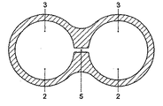
図5も、2つのチャンバ4、4’を設けたパッケージを有する。この場合、流体流妨害部は、パッケージ内の、チャンバ4がチャンバ4’に接続されている位置に設けられたグリッド6を有する。しかしながら、チャンバ4及びチャンバ4’は一体物であると見なされることができ、この一体物のほぼ中央にガーゼ又はグリッドを設け、それにより、パッケージ空間3を、少なくとも形状に関して手動で変化させるときに発生することができる流体流を妨害できるようにすると言うこともできるであろう。本例では、パッケージが少なくとも部分的に可撓性材料から製造されるので、これが可能である。流体がガーゼ又はグリッド6を通って流れるとき、液体が妨害されるためにガス及び液体が混ざり合うので、泡立ちも起こるであろう。
FIG. 5 also has a package provided with two
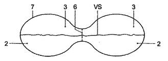
図6aには、本発明によるパッケージの好適な実施形態の上面図が示されている。この場合、パッケージ1のチャンバ4、4’の各々が、下向きの膨出部UB、UB’を有する。この場合、各膨出部UB、UB’は、可撓性材料から製造される。したがって、膨出部を上方向に、たとえば、矢印Sの方向に押し込むことが可能である。第1膨出部UBを、次に膨出部UB’を交互に押し込むことにより、パッケージ内に存在する液体及びガスがそれぞれチャンバ4からチャンバ4’に流れ、且つチャンバ4’からチャンバ4に戻るであろう。この場合も、この流体流はチャンバ5を経て行われなければならないであろう。流体がチャネル5などの流体流妨害部を通って流れるときに起きる上記効果は、この場合にも泡立ちをもたらす。このパッケージは、対称的に構成されており、さらには比較的廉価且つ簡単なやり方で製造されることができる。パッケージの、図6bに示されている部分は、それぞれ膨出部UB、UB’を有する2つのカップ形部分を設けたプラスチック上部シートを有することができる。チャネル5も、図6bに示された部分内に含まれることができる。パッケージの、図6aに示された部分は、図6に示された上側で膨出部UB、UB’及びチャネル5を閉め切る、任意選択で透明のプラスチック上部シートを備えることができ、それにより、密閉パッケージになる。その場合、図6aの斜線部分は、透明な上部シートのために見える、2枚のプラスチックシートが互いに取り付けられている接触面として機能することができる。
FIG. 6a shows a top view of a preferred embodiment of the package according to the invention. In this case, each of the
図7aには、図6aに示されているものと同様なパッケージの上面図が示されている。しかしながら、この場合にはチャネル5は、流体流内に乱れを起こすための乱流手段も備えている。この場合、乱流手段は、チャネル5内に設けられたチャネル5の拡幅部を有する。乱流手段は、チャネル5内に障害物を有することも可能である。
FIG. 7a shows a top view of a package similar to that shown in FIG. 6a. In this case, however, the
図1a、図2、図3、図4及び図5に示されている実施形態では、液位VSが示されている。好ましくは、図示の実施形態の位置では、この液位VSは、液位が流体流妨害部を通って延びるようなものであると考えられる。その結果、ほぼすべての場合で、液体が移動するとき、一定量のガスが流体流妨害部内へ一緒に運ばれ、それにより、ガス及び液体の混合を行うことができ、泡立ちをもたらすことができる。 In the embodiment shown in FIGS. 1a, 2, 3, 4 and 5, the liquid level VS is shown. Preferably, at the position of the illustrated embodiment, the liquid level VS is considered such that the liquid level extends through the fluid flow obstruction. As a result, in almost all cases, as the liquid moves, a certain amount of gas is carried together into the fluid flow obstruction, thereby allowing mixing of the gas and liquid, resulting in foaming. .
各実施形態について、やはり本発明による方法をそれによって実行することが可能であると考えられる。本方法は、ガスと、少なくともある程度泡立ち可能な液体とを含むパッケージ内に泡を得ることを対象とする。本方法は、液体及びガスをパッケージ内で移動させることを含む。本方法はまた、液体及びガスのパッケージ空間を、少なくとも形状に関して変化させることを含む。形状に関する変化は、容積に関する変化を伴うことも可能である。 For each embodiment, it is also considered possible to carry out the method according to the invention. The method is directed to obtaining foam in a package comprising a gas and at least some foamable liquid. The method includes moving liquid and gas within the package. The method also includes changing the liquid and gas package spaces at least in terms of shape. Changes in shape can be accompanied by changes in volume.
本発明によるそのようなパッケージ及び方法は、泡層を有して直ぐに消費されるのに適するコーヒーを淹れるための、やはり本発明による方法に使用されることができる。そのような方法は、少なくともある程度泡立った液体をパッケージから分離すること、及び、たとえば水及び/又はミルクなどの飲用可能な液体を少なくともある程度泡立った液体に加えることも含む。これにより、今日需要がある、泡層を有する一杯のコーヒーを抽出物から淹れることが可能である。 Such a package and method according to the invention can also be used in a method according to the invention for brewing coffee that has a foam layer and is suitable for immediate consumption. Such methods also include separating at least some foamy liquid from the package and adding a drinkable liquid such as water and / or milk to the at least some foamy liquid. This makes it possible to make a cup of coffee with a foam layer, which is in demand today, from the extract.
本発明は、図示の説明的実施形態にいかなる形でも制限されない。たとえば、手段は、それぞれが少なくとも1つのチャンバ4、4’を有し、且つ互いに接続可能である少なくとも2つの個別部分を備えることが可能である。その場合、少なくとも2つのチャンバの少なくとも1つにガスが少なくとも部分的に満たされ、少なくとも2つのチャンバの少なくとも別の1つに液体が少なくとも部分的に満たされると考えることができる。たとえば、ガスの入ったチャンバを一度、供給又は販売し、且つ毎回、液体を含む新しいチャンバに再度接続可能にすることができる。上述したように、パッケージは透明に構成されることが好ましい。
The present invention is not limited in any way to the illustrative embodiments shown. For example, the means can comprise at least two separate parts each having at least one
パッケージ内の液体は、抽出物から成ることができる。好ましくは、この場合はコーヒー抽出物が含まれ、任意選択であるが、これにコーヒーミルク抽出物が含まれる。たとえば、カプチーノ抽出物を含むことができる。所望ならば、そのような抽出物に香りを付けることができる。しかしながら、他の抽出物も可能である。ここでは、ココア抽出物、果汁抽出物及びスープ抽出物を考えることができる。しかしながら、液体は、泡立たせることができる濃縮物又は他のインスタント製品から成ることもできる。 The liquid in the package can consist of an extract. Preferably, in this case, a coffee extract is included, and optionally, this includes a coffee milk extract. For example, cappuccino extract can be included. If desired, such extracts can be scented. However, other extracts are possible. Here, cocoa extracts, fruit juice extracts and soup extracts can be considered. However, the liquid can also consist of a concentrate or other instant product that can be foamed.
少なくともある程度泡立った液体とパッケージとを互いに分離することができるように、パッケージは、パッケージを開くための手段も有することができる。チャンバ4、4’は、チャンバ容積の減少時に、それらの各々が液体及びガスを流体流妨害部の方向に押し進めるように構成されることができる。
The package can also have means for opening the package so that at least some of the foamy liquid and the package can be separated from each other. The
そのような変更はすべて、本発明の枠組みに入ることが理解される。 It is understood that all such changes fall within the framework of the present invention.
Claims (22)
A method of brewing coffee having a foam layer and suitable for immediate consumption, using the method of claim 21, separating at least some foamy liquid from the package, and, for example, A method of brewing coffee comprising adding a drinkable liquid, such as water, to the at least some foamy liquid.
Applications Claiming Priority (2)
| Application Number | Priority Date | Filing Date | Title |
|---|---|---|---|
| NL1024012A NL1024012C2 (en) | 2003-07-28 | 2003-07-28 | Packaging containing a gas and a liquid that can be worked up at least partially into a foam with which a consumption can be prepared. |
| PCT/NL2004/000525 WO2005009865A1 (en) | 2003-07-28 | 2004-07-22 | Package with partly foamable liquid by means of which a refreshment can be prepared |
Publications (2)
| Publication Number | Publication Date |
|---|---|
| JP2007501639A true JP2007501639A (en) | 2007-02-01 |
| JP2007501639A5 JP2007501639A5 (en) | 2007-08-30 |
Family
ID=34102047
Family Applications (1)
| Application Number | Title | Priority Date | Filing Date |
|---|---|---|---|
| JP2006521796A Pending JP2007501639A (en) | 2003-07-28 | 2004-07-22 | A liquid-filled package that can be used to make beverages |
Country Status (11)
| Country | Link |
|---|---|
| US (1) | US7790211B2 (en) |
| EP (1) | EP1660388B1 (en) |
| JP (1) | JP2007501639A (en) |
| AT (1) | ATE509859T1 (en) |
| AU (1) | AU2004259603B2 (en) |
| DK (1) | DK1660388T3 (en) |
| ES (1) | ES2366786T3 (en) |
| NL (1) | NL1024012C2 (en) |
| PL (1) | PL1660388T3 (en) |
| PT (1) | PT1660388E (en) |
| WO (1) | WO2005009865A1 (en) |
Families Citing this family (19)
| Publication number | Priority date | Publication date | Assignee | Title |
|---|---|---|---|---|
| US9358033B2 (en) | 2005-09-07 | 2016-06-07 | Ulthera, Inc. | Fluid-jet dissection system and method for reducing the appearance of cellulite |
| US8518069B2 (en) | 2005-09-07 | 2013-08-27 | Cabochon Aesthetics, Inc. | Dissection handpiece and method for reducing the appearance of cellulite |
| US9486274B2 (en) | 2005-09-07 | 2016-11-08 | Ulthera, Inc. | Dissection handpiece and method for reducing the appearance of cellulite |
| US9011473B2 (en) | 2005-09-07 | 2015-04-21 | Ulthera, Inc. | Dissection handpiece and method for reducing the appearance of cellulite |
| US10548659B2 (en) | 2006-01-17 | 2020-02-04 | Ulthera, Inc. | High pressure pre-burst for improved fluid delivery |
| US7885793B2 (en) | 2007-05-22 | 2011-02-08 | International Business Machines Corporation | Method and system for developing a conceptual model to facilitate generating a business-aligned information technology solution |
| US9248317B2 (en) | 2005-12-02 | 2016-02-02 | Ulthera, Inc. | Devices and methods for selectively lysing cells |
| US8439940B2 (en) | 2010-12-22 | 2013-05-14 | Cabochon Aesthetics, Inc. | Dissection handpiece with aspiration means for reducing the appearance of cellulite |
| US8167280B2 (en) | 2009-03-23 | 2012-05-01 | Cabochon Aesthetics, Inc. | Bubble generator having disposable bubble cartridges |
| DE102009034320A1 (en) * | 2009-07-23 | 2011-02-03 | Wmf Württembergische Metallwarenfabrik Ag | Container for containing liquid i.e. milk, has folded area for producing milk foam, and chamber provided for containing beverage component, where volume increase of container is balanced by air, and area of wall of container is transparent |
| US9358064B2 (en) | 2009-08-07 | 2016-06-07 | Ulthera, Inc. | Handpiece and methods for performing subcutaneous surgery |
| US11096708B2 (en) | 2009-08-07 | 2021-08-24 | Ulthera, Inc. | Devices and methods for performing subcutaneous surgery |
| GB2487895B (en) | 2010-07-19 | 2012-12-26 | Kraft Foods R & D Inc | Improvements in containers |
| GB2482283A (en) * | 2010-07-19 | 2012-02-01 | Kraft Foods R & D Inc | Foamed beverage pack |
| US9783361B2 (en) | 2013-03-14 | 2017-10-10 | Starbucks Corporation | Stretchable beverage cartridges and methods |
| EP3021685B1 (en) | 2013-07-15 | 2017-12-13 | Nestec S.A. | Self-foaming ready to drink beverages |
| US10442610B2 (en) | 2014-03-11 | 2019-10-15 | Starbucks Corporation | Pod-based restrictors and methods |
| US9877495B2 (en) | 2015-01-09 | 2018-01-30 | Starbucks Corporation | Method of making a sweetened soluble beverage product |
| FR3134696A1 (en) * | 2022-04-20 | 2023-10-27 | L'oreal | Set for preparing a cosmetic product and associated process |
Citations (7)
| Publication number | Priority date | Publication date | Assignee | Title |
|---|---|---|---|---|
| US1982884A (en) * | 1932-02-16 | 1934-12-04 | Schroder Einar | Apparatus for production of foam by mechanical means |
| JPS5592130A (en) * | 1980-01-14 | 1980-07-12 | Masao Moriyama | Mixer |
| JPS6097032A (en) * | 1983-09-02 | 1985-05-30 | リデツクス コ−ポレイシヨン リミテイド | Method and apparatus for collecting gas into substance |
| DE3838530A1 (en) * | 1988-11-14 | 1990-05-17 | Hilti Ag | Packaging for two-component compounds |
| JPH08228932A (en) * | 1994-11-22 | 1996-09-10 | Frabosk Casalinghi Spa | Milk server with beater to make capucino,etc. |
| US5939122A (en) * | 1996-09-23 | 1999-08-17 | Brady; Frank A. | Method for frothing liquids |
| JP2004528143A (en) * | 2001-06-08 | 2004-09-16 | サラ リー/デーイー エヌ.ヴェー | Apparatus and method for making a foamed beverage suitable for eating and drinking |
Family Cites Families (9)
| Publication number | Priority date | Publication date | Assignee | Title |
|---|---|---|---|---|
| DE2715582C2 (en) * | 1977-04-07 | 1979-09-06 | Juergen 3321 Salzgitter Zimmermann | Device for producing a beverage from ground coffee beans with a chamber delimited by filter walls for receiving the coffee grounds |
| JPS62298433A (en) * | 1986-06-19 | 1987-12-25 | Tdk Corp | Method and apparatus for mixing powdery granule |
| DE4332387C2 (en) | 1993-09-23 | 2002-06-27 | Poccino Espresso Gmbh | Process for making and offering cappuccino |
| US6740345B2 (en) | 2000-12-22 | 2004-05-25 | Edward Zhihua Cai | Beverage making cartridge |
| GB2373710B (en) | 2001-03-26 | 2005-01-26 | Patrick Arnold Lowe | Instant beverage spoon |
| ES2280640T3 (en) | 2003-03-24 | 2007-09-16 | Nestec S.A. | DISPOSABLE PACKING FOR THE DISTRIBUTION OF A PUMPABLE LIQUID PREPARATION FOR A VENTURI EFFECT DEVICE. |
| US9049961B2 (en) | 2003-12-22 | 2015-06-09 | Koninklijke Philips N.V. | Liquid cartridge for use in a beverage system |
| NL1029155C2 (en) | 2004-10-19 | 2006-04-20 | Sara Lee De Nv | System and method for preparing a drink suitable for consumption. |
| NL1033923C2 (en) | 2007-06-01 | 2008-12-02 | Sara Lee De Nv | Method and device for activating and emptying beverage preparation containers. |
-
2003
- 2003-07-28 NL NL1024012A patent/NL1024012C2/en not_active IP Right Cessation
-
2004
- 2004-07-22 DK DK04774833.0T patent/DK1660388T3/en active
- 2004-07-22 AT AT04774833T patent/ATE509859T1/en active
- 2004-07-22 ES ES04774833T patent/ES2366786T3/en active Active
- 2004-07-22 US US10/565,946 patent/US7790211B2/en not_active Expired - Fee Related
- 2004-07-22 AU AU2004259603A patent/AU2004259603B2/en not_active Ceased
- 2004-07-22 EP EP04774833A patent/EP1660388B1/en not_active Not-in-force
- 2004-07-22 WO PCT/NL2004/000525 patent/WO2005009865A1/en active Application Filing
- 2004-07-22 JP JP2006521796A patent/JP2007501639A/en active Pending
- 2004-07-22 PL PL04774833T patent/PL1660388T3/en unknown
- 2004-07-22 PT PT04774833T patent/PT1660388E/en unknown
Patent Citations (7)
| Publication number | Priority date | Publication date | Assignee | Title |
|---|---|---|---|---|
| US1982884A (en) * | 1932-02-16 | 1934-12-04 | Schroder Einar | Apparatus for production of foam by mechanical means |
| JPS5592130A (en) * | 1980-01-14 | 1980-07-12 | Masao Moriyama | Mixer |
| JPS6097032A (en) * | 1983-09-02 | 1985-05-30 | リデツクス コ−ポレイシヨン リミテイド | Method and apparatus for collecting gas into substance |
| DE3838530A1 (en) * | 1988-11-14 | 1990-05-17 | Hilti Ag | Packaging for two-component compounds |
| JPH08228932A (en) * | 1994-11-22 | 1996-09-10 | Frabosk Casalinghi Spa | Milk server with beater to make capucino,etc. |
| US5939122A (en) * | 1996-09-23 | 1999-08-17 | Brady; Frank A. | Method for frothing liquids |
| JP2004528143A (en) * | 2001-06-08 | 2004-09-16 | サラ リー/デーイー エヌ.ヴェー | Apparatus and method for making a foamed beverage suitable for eating and drinking |
Also Published As
| Publication number | Publication date |
|---|---|
| ES2366786T3 (en) | 2011-10-25 |
| AU2004259603B2 (en) | 2009-05-21 |
| PL1660388T3 (en) | 2011-11-30 |
| ATE509859T1 (en) | 2011-06-15 |
| EP1660388B1 (en) | 2011-05-18 |
| US7790211B2 (en) | 2010-09-07 |
| US20070031545A1 (en) | 2007-02-08 |
| EP1660388A1 (en) | 2006-05-31 |
| DK1660388T3 (en) | 2011-09-12 |
| NL1024012C2 (en) | 2005-02-01 |
| PT1660388E (en) | 2011-08-02 |
| WO2005009865A1 (en) | 2005-02-03 |
| AU2004259603A1 (en) | 2005-02-03 |
Similar Documents
| Publication | Publication Date | Title |
|---|---|---|
| JP2007501639A (en) | A liquid-filled package that can be used to make beverages | |
| KR101302456B1 (en) | System for preparing a predetermined amount of beverage suitable for consumption and Exchangeable holder | |
| JP2007501639A5 (en) | ||
| CN102357027A (en) | Foamed cleanser with suspended particles, method of producing the same, and dispenser thereof | |
| US9624024B2 (en) | Push up cereal cup | |
| FR2861564B3 (en) | DEVICE FOR PREPARING BEVERAGES COMPRISING A FOAMING ELEMENT. | |
| US6331131B1 (en) | Self inflating noise maker | |
| JP7083207B2 (en) | Triangular container for cosmetics | |
| JP3225011U (en) | Whisk, seasoning foaming method, food foaming method, beverage foaming method, facial cleansing foaming method, hair styling foaming method, detergent foaming method, construction material foaming method, industrial machine oil stirring method | |
| KR200440656Y1 (en) | Device For Preparing Hot Beverage | |
| JP6845805B2 (en) | Mug | |
| JP5303812B2 (en) | Dripper with the action of activating liquid | |
| CN217090461U (en) | Hand milk frother | |
| JP2004075087A (en) | Can for carbonated beverage such as beer | |
| KR20100060583A (en) | Coffe mug with bubble generator for bubbling and stirring | |
| JP3852678B2 (en) | Drinking control structure for drinking containers | |
| KR20080103035A (en) | Stirring cup and device | |
| US20160288980A1 (en) | Improved apparatus and method for a push up cereal cup | |
| JP3104888U (en) | Accessory member that mimics the movement of bubbles in a carbonated beverage in a container | |
| TW469122B (en) | Hygenicup | |
| JP6094860B2 (en) | pitcher | |
| TWM411197U (en) | Brewing structure with liquid activation | |
| RU2206130C1 (en) | Advertisement apparatus | |
| JPH0516127Y2 (en) | ||
| WO2011092496A1 (en) | Foam generating device |
Legal Events
| Date | Code | Title | Description |
|---|---|---|---|
| A521 | Request for written amendment filed |
Free format text: JAPANESE INTERMEDIATE CODE: A523 Effective date: 20070706 |
|
| A621 | Written request for application examination |
Free format text: JAPANESE INTERMEDIATE CODE: A621 Effective date: 20070706 |
|
| A131 | Notification of reasons for refusal |
Free format text: JAPANESE INTERMEDIATE CODE: A131 Effective date: 20100419 |
|
| A521 | Request for written amendment filed |
Free format text: JAPANESE INTERMEDIATE CODE: A523 Effective date: 20100715 |
|
| A02 | Decision of refusal |
Free format text: JAPANESE INTERMEDIATE CODE: A02 Effective date: 20100811 |
|
| A521 | Request for written amendment filed |
Free format text: JAPANESE INTERMEDIATE CODE: A523 Effective date: 20101210 |
|
| A911 | Transfer to examiner for re-examination before appeal (zenchi) |
Free format text: JAPANESE INTERMEDIATE CODE: A911 Effective date: 20101217 |
|
| A912 | Re-examination (zenchi) completed and case transferred to appeal board |
Free format text: JAPANESE INTERMEDIATE CODE: A912 Effective date: 20110225 |