JP2007335190A - Multi-direction slide type electronic component - Google Patents

Multi-direction slide type electronic component Download PDF

Info

Publication number
JP2007335190A
JP2007335190A JP2006164636A JP2006164636A JP2007335190A JP 2007335190 A JP2007335190 A JP 2007335190A JP 2006164636 A JP2006164636 A JP 2006164636A JP 2006164636 A JP2006164636 A JP 2006164636A JP 2007335190 A JP2007335190 A JP 2007335190A
Authority
JP
Japan
Prior art keywords
knob
switch
slide
pressing
electronic component
Prior art date
Legal status (The legal status is an assumption and is not a legal conclusion. Google has not performed a legal analysis and makes no representation as to the accuracy of the status listed.)
Granted
Application number
JP2006164636A
Other languages
Japanese (ja)
Other versions
JP4675282B2 (en
Inventor
Tetsuji Namiki
哲二 並木
Masahito Suyama
真仁 須山
Current Assignee (The listed assignees may be inaccurate. Google has not performed a legal analysis and makes no representation or warranty as to the accuracy of the list.)
Teikoku Tsushin Kogyo Co Ltd
Original Assignee
Teikoku Tsushin Kogyo Co Ltd
Priority date (The priority date is an assumption and is not a legal conclusion. Google has not performed a legal analysis and makes no representation as to the accuracy of the date listed.)
Filing date
Publication date
Application filed by Teikoku Tsushin Kogyo Co Ltd filed Critical Teikoku Tsushin Kogyo Co Ltd
Priority to JP2006164636A priority Critical patent/JP4675282B2/en
Publication of JP2007335190A publication Critical patent/JP2007335190A/en
Application granted granted Critical
Publication of JP4675282B2 publication Critical patent/JP4675282B2/en
Expired - Fee Related legal-status Critical Current
Anticipated expiration legal-status Critical

Links

Images

Abstract

<P>PROBLEM TO BE SOLVED: To provide a multi-direction slide type electronic component capable of surely and smoothly performing movement without unstably moving in the moving of a slide knob. <P>SOLUTION: The multi-direction slide type electronic component 1 is equipped with the slide knob 30 and a knob holding member 60. The knob holding member 60 is composed by integrating forming a knob mounting part 61 for mounting the slide knob 30, a frame body 63 for surrounding the knob mounting part 61, and an arm part 65 having flexibility for connecting so that the knob mounting part 61 becomes freely slidable in the multi-direction of the same surface with respect to the frame body 63. A switch pressing part 73 forming a conductive body 75 is provided in the frame body 63. A pressing part 37 for moving the switch pressing part 73 downward by pressing switch pressing part 73 is provided on the slide knob 30 when the slide knob 30 is slidingly moved. A switch 75 is disposed at the position where the moving switch pressing part 73 is abutted. <P>COPYRIGHT: (C)2008,JPO&INPIT

Description

本発明は、電子機器の入力装置等に用いて好適な多方向スライド式電子部品に関するものである。   The present invention relates to a multi-directional slide electronic component suitable for use in an input device of an electronic device.

従来、各種携帯機器等の中には、操作つまみを平面上で多方向にスライド移動させることで所望の出力を得るものがある(特許文献1参照)。図9はこの種の多方向スライド式電子部品の1例を示す図である。同図(a)に示すようにこの多方向スライド式電子部品500は、ケース510内に弾性体を枠形状であって中央に矩形状の開孔531を設け且つその4隅に外方に延びるアーム部533を設けてなる弾性支持部材530を収納し、弾性支持部材530の開孔531内にスライドつまみ550を収納し、また弾性支持部材530の外周側の4面にそれぞれ導電体535を取り付け、ケース510の内面の各導電体535に対向する位置にそれぞれ一対のスイッチ537を設置して構成されている。そして図9(b)に示すようにスライドつまみ550を1方向にスライド移動させると、弾性支持部材530が変形することでスライド移動した側の導電体535がスイッチ537に当接しこれをオンする。前記スライドつまみ550への押圧を解除すると、弾性支持部材530の元の形への弾性復帰力で、スライドつまみ550は図9(a)に示す元の中立位置に自動復帰する。   2. Description of the Related Art Conventionally, various portable devices and the like obtain a desired output by sliding an operation knob in multiple directions on a plane (see Patent Document 1). FIG. 9 is a view showing an example of this type of multi-directional sliding electronic component. As shown in FIG. 5A, this multi-directional sliding electronic component 500 has a case 510 with an elastic body having a frame shape, a rectangular opening 531 in the center, and extending outwardly at the four corners. The elastic support member 530 provided with the arm portion 533 is accommodated, the slide knob 550 is accommodated in the opening 531 of the elastic support member 530, and the conductors 535 are attached to the four outer peripheral surfaces of the elastic support member 530, respectively. In addition, a pair of switches 537 are installed at positions facing the respective conductors 535 on the inner surface of the case 510. 9B, when the slide knob 550 is slid in one direction, the elastic support member 530 is deformed and the slidable conductor 535 comes into contact with the switch 537 to turn it on. When the pressure on the slide knob 550 is released, the slide knob 550 automatically returns to the original neutral position shown in FIG. 9A by the elastic return force of the elastic support member 530 to the original shape.

しかしながら上記従来の多方向スライド式電子部品500においては、以下のような問題点があった。
(1)スライドつまみ550は枠形状の弾性支持部材530の開孔531内に保持されているだけなので、スライドつまみ550をスライド移動した後のスライドつまみ550の中立位置への自動復帰力は強くなく自動復帰時のスライドつまみ550の動きが緩慢で、スライドつまみ550の早急且つスムーズな自動復帰が望まれる場合にはその要望に答えられなかった。
(2)弾性支持部材530のアーム部533はケース510内に固定されておらず、またスライドつまみ550は枠形状の弾性支持部材530の開孔531内に保持されているだけで固定されていないので、スライドつまみ550をスライド移動させた際にその移動にふらつきが生じ易く、その動きが不正確になってしまう恐れがあった。
(3)ケース510の内周壁面にスイッチ537を設ける必要があるため、構造が複雑となり、小型化・薄型化が阻害されてしまう。
特開2003−31076号公報
However, the conventional multi-directional sliding electronic component 500 has the following problems.
(1) Since the slide knob 550 is only held in the opening 531 of the frame-shaped elastic support member 530, the automatic return force to the neutral position of the slide knob 550 after sliding the slide knob 550 is not strong. When the movement of the slide knob 550 at the time of automatic return is slow and the quick and smooth automatic return of the slide knob 550 is desired, the request cannot be answered.
(2) The arm portion 533 of the elastic support member 530 is not fixed in the case 510, and the slide knob 550 is only fixed in the opening 531 of the frame-shaped elastic support member 530 and is not fixed. Therefore, when the slide knob 550 is slid, the movement is likely to fluctuate, and the movement may be inaccurate.
(3) Since it is necessary to provide the switch 537 on the inner peripheral wall surface of the case 510, the structure is complicated, and downsizing and thinning are hindered.
JP 2003-31076 A

本発明は上述の点に鑑みてなされたものでありその目的は、スライドつまみの中立位置への自動復帰力が早急且つスムーズに行えると共に、スライドつまみの移動時の動きが確実にスムーズに行えてふらつくことなく、さらに部品点数が少なく構造が簡単で小型・薄型化を図ることができる多方向スライド式電子部品を提供することにある。   The present invention has been made in view of the above points, and its purpose is to enable an automatic return force to the neutral position of the slide knob quickly and smoothly and to ensure that the movement of the slide knob can be performed smoothly and smoothly. An object of the present invention is to provide a multi-directional slide type electronic component that does not fluctuate, has a smaller number of components, has a simple structure, and can be reduced in size and thickness.

本願請求項1に記載の発明は、スライドつまみと、前記スライドつまみを取り付けるつまみ取付部と、つまみ取付部の外周を囲む枠体と、つまみ取付部と枠体間を枠体に対してつまみ取付部が所定の方向にスライド自在となるように連結する可撓性を有するアーム部とを有してなるつまみ保持部材と、を具備し、前記枠体中に複数のスイッチ押圧部を設け、一方前記スライドつまみにこのスライドつまみがスライド移動した際に前記何れかのスイッチ押圧部を押圧する押圧部を設け、前記スイッチ押圧部の前記スライドつまみの押圧部が押圧する押圧面を、その押圧方向に対して傾斜する傾斜面とし、これによって前記スライドつまみの押圧部が前記押圧面を押圧することでスイッチ押圧部を前記押圧方向に対して交叉する方向に移動させると共に、前記スイッチ押圧部が移動した位置にスイッチを配置することで、スライドつまみのスライド方向に応じた出力を得ることを特徴とする多方向スライド式電子部品にある。   The invention according to claim 1 is a slide knob, a knob mounting portion to which the slide knob is attached, a frame body that surrounds the outer periphery of the knob mounting portion, and a knob mounting portion between the knob mounting portion and the frame body with respect to the frame body. A knob holding member having a flexible arm portion connected so that the portion is slidable in a predetermined direction, and provided with a plurality of switch pressing portions in the frame, The slide knob is provided with a pressing portion that presses any one of the switch pressing portions when the slide knob slides, and a pressing surface that the pressing portion of the slide knob of the switch pressing portion presses in the pressing direction. An inclined surface that is inclined with respect to this, and the pressing portion of the slide knob presses the pressing surface to move the switch pressing portion in a direction crossing the pressing direction. Both, by arranging the switch to the position where the switch pressing part is moved, in multi-directional slide type electronic component, characterized in that to obtain an output corresponding to the sliding direction of the slide knob.

本願請求項2に記載の発明は、前記つまみ保持部材を構成するつまみ取付部と枠体とアーム部は、弾性体によって一体に形成されていることを特徴とする請求項1に記載の多方向スライド式電子部品にある。   The invention according to claim 2 of the present application is characterized in that the knob mounting portion, the frame body and the arm portion constituting the knob holding member are integrally formed by an elastic body. It is in a sliding electronic component.

本願請求項3に記載の発明は、前記つまみ保持部材はスライドつまみと共に矩形状のケース内に収納され、前記つまみ保持部材の枠体は、前記ケースの4隅に設置される支持部と、各支持部間を連結する可撓性を有する連結部と、連結部の途中に設けられる前記スイッチ押圧部とを具備して構成され、前記アーム部は、枠体の内部に位置する前記つまみ取付部を、前記各支持部に対角線状に連結するように形成され、一方前記スライドつまみは、前記つまみ取付部の上面に設置され、その外周から前記各スイッチ押圧部の押圧面に対向する位置に延びる突出部を突出して設け、各突出部の先端を前記押圧部としたことを特徴とする請求項1又は2に記載の多方向スライド式電子部品にある。   In the invention according to claim 3 of the present application, the knob holding member is housed in a rectangular case together with the slide knob, and the frame body of the knob holding member includes support portions installed at four corners of the case, The knob mounting portion is configured to include a flexible connecting portion for connecting between the support portions and the switch pressing portion provided in the middle of the connecting portion, and the arm portion is located inside the frame body. The slide knob is installed on the upper surface of the knob mounting portion and extends from the outer periphery to a position facing the pressing surface of each switch pressing portion. The multi-directional sliding electronic component according to claim 1, wherein a protruding portion is provided so as to protrude, and a tip of each protruding portion is used as the pressing portion.

本願請求項4に記載の発明は、前記スイッチは、前記つまみ保持部材の下面側に設置したスイッチ基板の前記各スイッチ押圧部に対向する位置に設けられ、且つこのスイッチ基板の前記つまみ取付部に対向する位置に、つまみ取付部に取り付けた前記スライドつまみによって押圧される押釦スイッチを設けたことを特徴とする請求項1又は2又は3に記載の多方向スライド式電子部品にある。   In the invention according to claim 4 of the present application, the switch is provided at a position facing each of the switch pressing portions of the switch board installed on the lower surface side of the knob holding member, and on the knob mounting portion of the switch board. The multi-directional sliding electronic component according to claim 1, wherein a push button switch that is pressed by the slide knob attached to the knob attachment portion is provided at an opposing position.

請求項1に記載の発明によれば、スライドつまみをつまみ保持部材のつまみ取付部に取り付けており、且つつまみ取付部と枠体間をアーム部によって連結しているので、スライドつまみの中立位置への自動復帰力が強く、その自動復帰が早急且つスムーズに行えると共に、スライドつまみの移動時の動きがふらつくことなくスムーズ且つ確実に行える。またスイッチをスライドつまみの押圧部の押圧方向に対して交叉する方向に設置することができるので、スイッチをスイッチ押圧部の外側に設置しなくても良く、この多方向スライド式電子部品の外形の小型化が図れる。また多方向スライド式電子部品を構成する部品点数が少なく、構造が簡単で、小型・薄型化を図ることができる。   According to the first aspect of the present invention, the slide knob is attached to the knob attachment portion of the knob holding member, and the knob attachment portion and the frame body are connected by the arm portion. The automatic return force is strong, the automatic return can be performed quickly and smoothly, and the movement of the slide knob can be performed smoothly and reliably without wobbling. In addition, since the switch can be installed in a direction crossing the pressing direction of the pressing portion of the slide knob, the switch need not be installed outside the pressing portion of the switch. Miniaturization can be achieved. In addition, the number of components constituting the multi-directional sliding electronic component is small, the structure is simple, and the size and thickness can be reduced.

請求項2に記載の発明によれば、つまみ保持部材を構成するつまみ取付部と枠体とアーム部とを一体に形成したので、構造を簡素化することができる。   According to the second aspect of the present invention, since the knob mounting portion, the frame body, and the arm portion constituting the knob holding member are integrally formed, the structure can be simplified.

請求項3に記載の発明によれば、つまみ保持部材に支持部を設けたので、つまみ保持部材をスライドつまみと共に容易且つ確実にケース内に収納することができる。またつまみ取付部をアーム部によって各支持部に対角線状に連結するようにしたので、スライドつまみを容易且つふらつくことなく確実且つ早急且つスムーズに多方向にスライド移動するように保持することができる。またスライドつまみに突出部を設けてその先端を押圧部としたので、つまみ取付部上面に設置されたスライドつまみによる各スイッチ押圧部の押圧面の押圧が容易に行える。   According to the third aspect of the present invention, since the support portion is provided on the knob holding member, the knob holding member can be easily and reliably accommodated in the case together with the slide knob. Further, since the knob mounting portion is diagonally connected to each support portion by the arm portion, it is possible to hold the slide knob so that it can be easily and quickly slid in multiple directions without wobbling easily and smoothly. Further, since the projecting portion is provided on the slide knob and the tip thereof is used as the pressing portion, the pressing surface of each switch pressing portion can be easily pressed by the slide knob installed on the upper surface of the knob mounting portion.

請求項4に記載の発明によれば、スイッチ基板上に、スイッチと押釦スイッチとを設けることができ、それぞれを別のスイッチ基板等に設ける場合に比べて部品点数を少なくでき構造が簡単になり小型・薄型化を図ることができる。   According to the fourth aspect of the present invention, the switch and the push button switch can be provided on the switch board, and the number of parts can be reduced and the structure is simplified as compared with the case where each is provided on another switch board or the like. Smaller and thinner can be achieved.

以下、本発明の実施形態を図面に基づいて詳細に説明する。
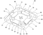
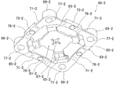
図1,図2は本発明の1実施形態にかかる多方向スライド式電子部品1の分解斜視図であり、両図を合せて1つの分解斜視図となっている。両図に示すように多方向スライド式電子部品1は、ケース(以下この実施形態では「下ケース」という)110上に、スイッチ基板100と、摺動シート90と、つまみ保持部材60と、スライドつまみ30と、ケース(以下この実施形態では「上ケース」という)10とを取り付けて構成されている。以下各構成部品について説明する。
Hereinafter, embodiments of the present invention will be described in detail with reference to the drawings.
1 and 2 are exploded perspective views of a multi-directional sliding electronic component 1 according to an embodiment of the present invention, and both drawings are combined into a single exploded perspective view. As shown in both figures, the multi-directional sliding electronic component 1 includes a switch substrate 100, a sliding sheet 90, a knob holding member 60, and a slide on a case 110 (hereinafter referred to as “lower case” in this embodiment). A knob 30 and a case (hereinafter referred to as “upper case” in this embodiment) 10 are attached. Each component will be described below.

上ケース10は金属板(この実施形態ではステンレス板)を下面が開放された矩形状の箱型に形成することで構成されており、具体的には矩形状の上面部11の外周4辺に下方向に向かう側壁部13を設けて構成されている。上面部11の中央には略十字型に貫通するつまみ挿通ガイド部15が設けられ、また上面部11の4隅近傍には貫通する小孔からなる挿通部17が設けられている。   The upper case 10 is formed by forming a metal plate (in this embodiment, a stainless steel plate) into a rectangular box shape having an open lower surface. Specifically, the upper case 10 is formed on the four outer sides of the rectangular upper surface portion 11. A side wall portion 13 directed downward is provided. A knob insertion guide portion 15 that penetrates in a substantially cross shape is provided at the center of the upper surface portion 11, and insertion portions 17 that are small holes that penetrate therethrough are provided in the vicinity of the four corners of the upper surface portion 11.

図3はスライドつまみ30を下面側から見た斜視図である。図1,図3に示すように、スライドつまみ30は合成樹脂(例えば熱可塑性合成樹脂であるABS樹脂やPBT樹脂やPOM樹脂等)の成形品であり、略円板状の基部31の上面中央から上方向に向かって柱状のつまみ部33を立設し、また基部31の外周から等間隔(90°間隔)に四本の平板帯状の突出部35を突出し、各突出部35の先端面を押圧部37とし、また基部31の下面中央に下方向に向かってスイッチ押圧部39を突出して構成されている。つまみ部33は四角柱状であってその上端面には操作つまみ130(図5参照)取付用の係合穴41が設けられている。押圧部37は突出部35の先端面を下方向(つまみ保持部材60方向)に向かってスライドつまみ30の中央に近づく方向の傾斜面として構成されている。各押圧部37の下端辺中央には小突起状に突出するスライド部43が設けられている。各押圧部37の上部の突出部35の上面にも小円弧状に突出するスライド部45が設けられている。またスイッチ押圧部39は基部31の下面中央から突出する小突起によって構成され、その根元部分の外周からは等間隔に複数(4つ)の係合部47を突出している。   FIG. 3 is a perspective view of the slide knob 30 as viewed from the lower surface side. As shown in FIGS. 1 and 3, the slide knob 30 is a molded product of a synthetic resin (for example, ABS resin, PBT resin, POM resin or the like which is a thermoplastic synthetic resin), and is centered on the upper surface of a substantially disc-shaped base 31. Column-shaped knobs 33 are erected upward from the top, and four flat belt-like protrusions 35 protrude from the outer periphery of the base 31 at equal intervals (90 ° intervals). A pressing portion 37 is formed, and a switch pressing portion 39 protrudes downward from the center of the lower surface of the base portion 31. The knob portion 33 has a quadrangular prism shape, and an engagement hole 41 for attaching the operation knob 130 (see FIG. 5) is provided on the upper end surface thereof. The pressing portion 37 is configured as an inclined surface in a direction approaching the center of the slide knob 30 toward the lower end (in the direction of the knob holding member 60) of the tip surface of the protruding portion 35. At the center of the lower end side of each pressing portion 37, a slide portion 43 protruding in a small protrusion shape is provided. A slide portion 45 that protrudes in a small arc shape is also provided on the upper surface of the protrusion 35 at the top of each pressing portion 37. Further, the switch pressing portion 39 is constituted by a small protrusion protruding from the center of the lower surface of the base portion 31, and a plurality (four) of engaging portions 47 protrude from the outer periphery of the base portion at equal intervals.

図4はつまみ保持部材60を下面側から見た斜視図である。図1,図4に示すようにつまみ保持部材60は、前記スライドつまみ30を取り付けるつまみ取付部61と、つまみ取付部61の外周を囲む枠体63と、つまみ取付部61と枠体63間を枠体63に対してつまみ取付部61が同一面内の多方向にスライド自在となるように連結する可撓性を有する4本のアーム部65とを有し、これら各構成部分を絶縁性の弾性体(この実施形態では絶縁性の合成ゴムであるシリコンゴムを用いている)によって一体成形して構成されている。   FIG. 4 is a perspective view of the knob holding member 60 as viewed from the lower surface side. As shown in FIGS. 1 and 4, the knob holding member 60 includes a knob attachment portion 61 for attaching the slide knob 30, a frame body 63 that surrounds the outer periphery of the knob attachment portion 61, and a space between the knob attachment portion 61 and the frame body 63. The knob attachment portion 61 is connected to the frame 63 so as to be slidable in multiple directions within the same plane, and has four arm portions 65 having flexibility. It is integrally formed of an elastic body (in this embodiment, silicon rubber which is an insulating synthetic rubber is used).

つまみ取付部61は薄板円板状であって、その外径寸法は前記スライドつまみ30の基部31の外径寸法と略同一に形成され、その中央には前記スライドつまみ30のスイッチ押圧部39及び係合部47を嵌合する略十字形状の貫通する挿入部67が設けられている。   The knob mounting portion 61 has a thin disc shape, and its outer diameter dimension is substantially the same as the outer diameter dimension of the base 31 of the slide knob 30, and the switch pressing portion 39 of the slide knob 30 and An insertion portion 67 having a substantially cross shape that fits the engaging portion 47 is provided.

枠体63は前記つまみ取付部61の周囲を矩形状に囲む形状に形成され、その4隅に設置される支持部69と、各支持部69間を連結する可撓性を有する連結部71とを具備している。連結部71の途中(中央)にはスイッチ押圧部73が設けられ、スイッチ押圧部73の下面には導電体75が設けられている。支持部69は柱状であり、その中央には上下に貫通する支持孔77が設けられている。各支持孔77は前記上ケース10の各挿通部17に対向する位置に各挿通部17よりも大径に形成されている。4本の連結部71は全体として各支持部69間を矩形状に連結するように取り付けられ、平板帯状で可撓性を有するように肉薄に形成されている。そして各連結部71の中央に前記スイッチ押圧部73が設けられている。スイッチ押圧部73はその長手方向を連結部71の長手方向と一致させた略矩形の柱状に形成されており、それらの内側面(つまみ取付部61側を向く面)に前記スライドつまみ30の押圧部37によって押圧される押圧面79を形成している。押圧面79は下方向(スイッチ基板100方向)に向かってつまみ取付部61の中央に近づく方向の傾斜面となっており、前記押圧部37の傾斜面と同一方向に傾斜する傾斜面となっている。スイッチ押圧部73の下面にはその略全体を覆う面積の導電体75が設けられている。導電体75は矩形状の導電性ゴムの平板によって構成されている。導電体75の下面はその両側の連結部71の下面よりも上方に位置するように、両側の連結部71によって少し上方に持ち上げられている。導電体75はつまみ保持部材60を成形する際の金型内に予め設置しておくことで、つまみ保持部材60の成形時に一体成形される。   The frame 63 is formed in a shape that surrounds the knob mounting portion 61 in a rectangular shape, and has support portions 69 installed at four corners thereof, and a flexible connection portion 71 that connects the support portions 69. It has. A switch pressing portion 73 is provided in the middle (center) of the connecting portion 71, and a conductor 75 is provided on the lower surface of the switch pressing portion 73. The support portion 69 has a columnar shape, and a support hole 77 penetrating vertically is provided at the center thereof. Each support hole 77 is formed in a larger diameter than each insertion portion 17 at a position facing each insertion portion 17 of the upper case 10. The four connecting portions 71 are attached so as to connect the support portions 69 in a rectangular shape as a whole, and are formed in a thin plate shape in a flat strip shape so as to have flexibility. The switch pressing portion 73 is provided at the center of each connecting portion 71. The switch pressing portion 73 is formed in a substantially rectangular column shape whose longitudinal direction coincides with the longitudinal direction of the connecting portion 71, and the slide knob 30 is pressed against the inner side surface thereof (the surface facing the knob mounting portion 61 side). A pressing surface 79 to be pressed by the portion 37 is formed. The pressing surface 79 is an inclined surface in a direction approaching the center of the knob mounting portion 61 in the downward direction (switch board 100 direction), and is an inclined surface inclined in the same direction as the inclined surface of the pressing portion 37. Yes. On the lower surface of the switch pressing portion 73, a conductor 75 having an area covering substantially the whole is provided. The conductor 75 is constituted by a rectangular conductive rubber flat plate. The lower surface of the conductor 75 is lifted slightly upward by the connecting portions 71 on both sides so as to be positioned above the lower surfaces of the connecting portions 71 on both sides. The conductor 75 is previously formed in a mold when the knob holding member 60 is formed, so that the conductor 75 is integrally formed when the knob holding member 60 is formed.

アーム部65は薄板帯状の平板であって、より可撓性を持たせるためにその中間において平板を上下方向に波打つように湾曲変形させている。各アーム部65は、枠体63の内部に位置するつまみ取付部61と各支持部69間を、各支持部69に対して対角線状に連結している。   The arm portion 65 is a thin plate-like flat plate, and is bent and deformed so as to wave in the vertical direction in the middle in order to have more flexibility. Each arm portion 65 connects the knob mounting portion 61 located inside the frame 63 and each support portion 69 diagonally to each support portion 69.

摺動シート90は、可撓性を有する絶縁性の合成樹脂フイルムを略矩形状に形成して構成されており、その4隅から舌片状の突出部91を突出し、それらの内部に円形の貫通する取付部93を設けて構成されている。各取付部93は、前記つまみ保持部材60の各支持孔77に対向する位置に各支持孔77とほぼ同一径に形成されている。この摺動シート90は、例えば合成樹脂フイルム上にフッ素樹脂をコーティングすることで、その表面に当接する前記スライドつまみ30のスライド部43やスイッチ押圧部39が抵抗なく摺動できるようにしている。なお摺動シート90はその表面が滑らかなものであれば、他の各種材質・構造のシートを用いても良い。   The sliding sheet 90 is formed by forming an insulating synthetic resin film having flexibility in a substantially rectangular shape, protruding tongue-like protruding portions 91 from four corners thereof, and a circular shape in the inside thereof. An attaching portion 93 that penetrates is provided. Each mounting portion 93 is formed to have the same diameter as each support hole 77 at a position facing each support hole 77 of the knob holding member 60. The sliding sheet 90 is coated with, for example, a fluororesin on a synthetic resin film so that the slide portion 43 and the switch pressing portion 39 of the slide knob 30 contacting the surface can slide without resistance. As long as the sliding sheet 90 has a smooth surface, sheets of other various materials and structures may be used.

スイッチ基板100は、可撓性を有する絶縁性の合成樹脂フイルム(この実施形態ではポリエチレンテレフタレートフイルム)を略矩形状に形成してなる絶縁基板101の表面中央に押釦スイッチ103を設け、その周囲の各辺に沿う其々の中央位置に一対ずつの接点パターン107からなるスイッチ105を設け、その4隅に円形に貫通する取付挿通部109を設けて構成されている。押釦スイッチ103は、下記する図6に示すように、一対の接点パターン103a,b上に反転板(この実施形態では可動接点板)103cを取り付けて構成されている。反転板103cは摺動シート90をスイッチ基板100上に貼り付けることで固定される。言い換えれば摺動シート90は反転板103cの貼付け用シートを兼用している。各取付挿通部109は、前記つまみ保持部材60の各支持孔77に対向する位置に各支持孔77とほぼ同一径で形成されている。絶縁基板101の外周には引出部103が一体に接続されており、前記押釦スイッチ103や各スイッチ105から引き出されている図示しない回路パターンをこの引出部103に引き出している。   The switch substrate 100 is provided with a push button switch 103 at the center of the surface of an insulating substrate 101 formed by forming a flexible insulating synthetic resin film (polyethylene terephthalate film in this embodiment) in a substantially rectangular shape. A switch 105 including a pair of contact patterns 107 is provided at each central position along each side, and mounting insertion portions 109 penetrating circularly are provided at four corners. As shown in FIG. 6 described below, the push button switch 103 is configured by attaching a reverse plate (movable contact plate in this embodiment) 103c on a pair of contact patterns 103a and 103b. The reversing plate 103 c is fixed by sticking the sliding sheet 90 on the switch substrate 100. In other words, the sliding sheet 90 also serves as a sheet for attaching the reversing plate 103c. Each attachment insertion portion 109 is formed at a position facing each support hole 77 of the knob holding member 60 with substantially the same diameter as each support hole 77. A drawing portion 103 is integrally connected to the outer periphery of the insulating substrate 101, and a circuit pattern (not shown) drawn from the push button switch 103 and each switch 105 is drawn to the drawing portion 103.

下ケース110は、合成樹脂(例えば熱可塑性合成樹脂であるABS樹脂やPBT樹脂やPOM樹脂等)を略矩形の板状であって、その上面の4隅から上方向に向けて円柱状の固定部111を突出するように成形して構成されている。各固定部111の上端面にはさらにその外径を小さくした挿入部113が設けられている。各固定部111は、前記つまみ保持部材60の各支持孔77に対向する位置に設けられ、各固定部111の外径は各支持孔77がちょうど挿入できる寸法に形成され、また前記挿入部113の外径は前記上ケース10の挿通部17がちょうど挿入できる寸法に形成されている。   The lower case 110 has a substantially rectangular plate shape made of synthetic resin (for example, ABS resin, PBT resin, or POM resin, which is a thermoplastic synthetic resin), and is fixed in a columnar shape from the four corners of the upper surface upward. The portion 111 is formed so as to protrude. An insertion portion 113 whose outer diameter is further reduced is provided on the upper end surface of each fixing portion 111. Each fixing portion 111 is provided at a position facing each support hole 77 of the knob holding member 60, and the outer diameter of each fixing portion 111 is formed such that each support hole 77 can be inserted exactly, and the insertion portion 113. The outer diameter of the upper case 10 is formed such that the insertion part 17 of the upper case 10 can be inserted.

次にこの多方向スライド式電子部品1を組み立てるには、まずつまみ保持部材60のつまみ取付部61上にスライドつまみ30の基部31を接着材によって接着・載置し、つまみ保持部材60の挿入部67にスライドつまみ30のスイッチ押圧部39を挿入する。このときスイッチ押圧部39の周囲に設けた略十字形状の係合部47を略十字形状の挿入部67に嵌合する。次に下ケース110上に、スイッチ基板100と、摺動シート90と、前記スライドつまみ30を取り付けたつまみ保持部材60とを載置する。その際、下ケース110に設けた各固定部111を、スイッチ基板100の各取付挿通部109と、摺動シート90の各取付部93と、つまみ保持部材60の各支持孔77とに挿入する。摺動シート90はスイッチ基板100上に摺動シート90の下面に設けた接着層で貼り付けられる(必ずしも貼り付けなくても良い)。次にその上に上ケース10を被せ、その際、スライドつまみ30のつまみ部33をつまみ挿通ガイド部15に挿入するとともに、下ケース110の各挿入部113を上ケース10の各挿通部17に挿入する。次に上ケース10上に突出する各挿入部113の先端を熱カシメすることで上ケース10を下ケース110に固定する。そして上ケース10上に図5に示す操作つまみ130を設置して上ケース10から突出するスライドつまみ30のつまみ部33を操作つまみ130の下面中央に設けた図示しない穴に嵌合して固定すれば、図5に示す多方向スライド式電子部品1が完成する。   Next, in order to assemble the multi-directional slide type electronic component 1, first, the base 31 of the slide knob 30 is bonded and placed on the knob mounting portion 61 of the knob holding member 60 with an adhesive, and the insertion portion of the knob holding member 60 is inserted. The switch pressing portion 39 of the slide knob 30 is inserted into 67. At this time, the substantially cross-shaped engaging portion 47 provided around the switch pressing portion 39 is fitted into the substantially cross-shaped insertion portion 67. Next, the switch substrate 100, the sliding sheet 90, and the knob holding member 60 to which the slide knob 30 is attached are placed on the lower case 110. At that time, the fixing portions 111 provided on the lower case 110 are inserted into the mounting insertion portions 109 of the switch board 100, the mounting portions 93 of the sliding sheet 90, and the support holes 77 of the knob holding member 60. . The sliding sheet 90 is affixed on the switch substrate 100 with an adhesive layer provided on the lower surface of the sliding sheet 90 (not necessarily affixed). Next, the upper case 10 is covered thereon, and at that time, the knob portion 33 of the slide knob 30 is inserted into the knob insertion guide portion 15, and each insertion portion 113 of the lower case 110 is inserted into each insertion portion 17 of the upper case 10. insert. Next, the upper case 10 is fixed to the lower case 110 by heat caulking the tip of each insertion portion 113 protruding on the upper case 10. 5 is installed on the upper case 10, and the knob 33 of the slide knob 30 protruding from the upper case 10 is fitted into a hole (not shown) provided at the center of the lower surface of the operation knob 130 and fixed. Thus, the multi-directional sliding electronic component 1 shown in FIG. 5 is completed.

図6は多方向スライド式電子部品1の中央部分を切断した断面斜視図である(但し、操作つまみ130の記載は省略)。同図においてスライドつまみ30のつまみ部33を同一平面上で直交するX軸又はY軸方向(挿通ガイド部15の十字の方向)に押圧すると、つまみ部33が上ケース10のつまみ挿通ガイド部15内を移動することで押圧された方向にスライド移動する。このときスライドつまみ30に設けたスライド部43が滑らかな表面を有する摺動シート90上を摺動するのでそのスライド移動には抵抗が少なく、スムーズなスライド移動が行える。なおスライド部43は静止状態では摺動シート90の上面には当接しないで少し浮いているが、スライドつまみ30を移動する際にスライドつまみ30が少し傾くと摺動シート90の上面に当接する。そしてスライドつまみ30が移動していく方向を向く突出部35の先端の押圧部37の傾斜面が、これに対向するスイッチ押圧部73の押圧面79に当接し、このスイッチ押圧部73の両側の連結部71が撓むことでスイッチ押圧部73は前記押圧方向に交叉(直交)する下方向に移動する。これによってスイッチ押圧部73の真下に取り付けている導電体75がこれに対向するスイッチ基板100上の一対の接点パターン107に同時に当接し、スイッチ105を導通(オン)する。前記つまみ部33への押圧を解除すれば、スライドつまみ30を移動したことで撓んでいた4本のアーム部65の元の形状に戻ろうとする復帰力によってスライドつまみ30はつまみ取付部61と一体に元の位置、つまり枠体63の中央に自動復帰し、同時に押圧部37による押圧面79の押圧が解除され且つ連結部71が元の形状に戻る力によってスイッチ押圧部73が上昇し、その導電体75がスイッチ105から離れ、スイッチ105がオフする。つまりこの多方向スライド式電子部品1によれば、スライドつまみ30のスライド方向に応じた出力を得ることができる。   FIG. 6 is a cross-sectional perspective view in which the central portion of the multi-directional sliding electronic component 1 is cut (however, the operation knob 130 is not shown). In the same figure, when the knob part 33 of the slide knob 30 is pressed in the X-axis or Y-axis direction (the cross direction of the insertion guide part 15) orthogonal to each other on the same plane, the knob part 33 becomes the knob insertion guide part 15 of the upper case 10. It slides in the pressed direction by moving inside. At this time, since the slide portion 43 provided on the slide knob 30 slides on the slide sheet 90 having a smooth surface, there is little resistance to the slide movement, and the smooth slide movement can be performed. Although the slide portion 43 does not come into contact with the upper surface of the sliding sheet 90 in a stationary state, it slightly floats. However, when the slide knob 30 is slightly inclined when the slide knob 30 is moved, it comes into contact with the upper surface of the sliding sheet 90. . The inclined surface of the pressing portion 37 at the tip of the projecting portion 35 facing the direction in which the slide knob 30 moves is in contact with the pressing surface 79 of the switch pressing portion 73 facing this, and on both sides of the switch pressing portion 73. When the connecting portion 71 is bent, the switch pressing portion 73 moves in a downward direction crossing (orthogonal) in the pressing direction. As a result, the conductor 75 attached immediately below the switch pressing portion 73 simultaneously contacts the pair of contact patterns 107 on the switch substrate 100 facing the switch 75, thereby turning on the switch 105. When the pressing to the knob portion 33 is released, the slide knob 30 is integrated with the knob mounting portion 61 by a restoring force for returning to the original shape of the four arm portions 65 bent by moving the slide knob 30. Automatically return to the original position, that is, the center of the frame 63, and at the same time, the pressing of the pressing surface 79 by the pressing portion 37 is released and the switch pressing portion 73 is raised by the force of the connecting portion 71 returning to its original shape. The conductor 75 is separated from the switch 105, and the switch 105 is turned off. That is, according to the multi-directional sliding electronic component 1, an output corresponding to the sliding direction of the slide knob 30 can be obtained.

以上のように本実施形態にかかる多方向スライド式電子部品1は、スライドつまみ30と、スライドつまみ30を取り付けるつまみ取付部61とつまみ取付部61の外周を囲む枠体63とつまみ取付部61と枠体63間を枠体63に対してつまみ取付部61が所定の方向(この実施形態では同一面内の多方向)にスライド自在となるように連結する可撓性を有するアーム部65とを有してなるつまみ保持部材60とを具備し、前記枠体63中に複数のスイッチ押圧部73を設け、一方スライドつまみ30にこのスライドつまみ30がスライド移動した際に何れかのスイッチ押圧部73を押圧する押圧部37を設け、さらにスライドつまみ30の押圧部37によって押圧されて移動したスイッチ押圧部73(その導電体75)が当接する位置にスイッチ105を配置して構成されている。つまりこの実施形態によれば、多方向スライド式電子部品1を構成する部品点数が少なくて済み、このことから多方向スライド式電子部品1の構造が簡単で、その小型・薄型化を図ることができる。   As described above, the multi-directional slide type electronic component 1 according to the present embodiment includes the slide knob 30, the knob attachment portion 61 to which the slide knob 30 is attached, the frame body 63 that surrounds the outer periphery of the knob attachment portion 61, and the knob attachment portion 61. A flexible arm portion 65 that connects the frame 63 so that the knob mounting portion 61 is slidable in a predetermined direction (multiple directions in the same plane in this embodiment) with respect to the frame 63. A plurality of switch pressing portions 73 provided in the frame 63, and one of the switch pressing portions 73 when the slide knob 30 slides on the slide knob 30. Is provided at a position where the switch pressing portion 73 (the conductor 75) moved by being pressed by the pressing portion 37 of the slide knob 30 abuts. It is constructed by placing the switch 105. That is, according to this embodiment, the number of parts constituting the multi-directional sliding electronic component 1 can be reduced, so that the structure of the multi-directional sliding electronic component 1 is simple, and the size and thickness can be reduced. it can.

またこの多方向スライド式電子部品1においては、スライドつまみ30をつまみ保持部材60のつまみ取付部61に取り付けており、且つつまみ取付部61と枠体63間をアーム部65によって連結しているので、スライドつまみ30の中立位置への自動復帰力が強く、その自動復帰が早急且つスムーズに行えると共に、スライドつまみ30の移動時の動きがふらつくことなくスムーズ且つ確実に行える。またスイッチ105をスライドつまみ30の押圧部37の押圧方向に対して交叉する方向に設置することができるので、スイッチ105をスイッチ押圧部73の外側に設置しなくても良く、この多方向スライド式電子部品1の外形の小型化が図れる。   In this multi-directional sliding electronic component 1, the slide knob 30 is attached to the knob attachment portion 61 of the knob holding member 60, and the knob attachment portion 61 and the frame 63 are connected by the arm portion 65. The automatic return force to the neutral position of the slide knob 30 is strong, the automatic return can be performed quickly and smoothly, and the movement of the slide knob 30 during the movement can be smoothly and reliably performed. Further, since the switch 105 can be installed in a direction crossing the pressing direction of the pressing portion 37 of the slide knob 30, the switch 105 does not have to be installed outside the switch pressing portion 73, and this multi-directional sliding type. The external size of the electronic component 1 can be reduced.

またこの多方向スライド式電子部品1においては、スイッチ押圧部73のスライドつまみ30の押圧部37が押圧する押圧面79を、その押圧方向に対して傾斜する傾斜面とし、これによってスライドつまみ30の押圧部37が押圧面79を押圧することでスイッチ押圧部73が押圧方向に対して交叉する方向に移動するように構成しているので、スイッチ105をスライドつまみ30の押圧部37の押圧方向に対して交叉する方向(この実施形態ではスイッチ押圧部73の下側であるが、スイッチ押圧部73の上側でもよい)に設置できる。即ちスイッチ105をスイッチ押圧部73の外側(枠体63の外周側)に設置しなくても良くなり、この多方向スライド式電子部品1の外形の小型化が図れる。   In the multi-directional slide type electronic component 1, the pressing surface 79 that is pressed by the pressing portion 37 of the slide knob 30 of the switch pressing portion 73 is an inclined surface that is inclined with respect to the pressing direction. Since the switch pressing portion 73 moves in a direction crossing the pressing direction when the pressing portion 37 presses the pressing surface 79, the switch 105 is moved in the pressing direction of the pressing portion 37 of the slide knob 30. It can be installed in the crossing direction (in this embodiment, it is the lower side of the switch pressing portion 73 but may be the upper side of the switch pressing portion 73). That is, it is not necessary to install the switch 105 on the outside of the switch pressing portion 73 (the outer peripheral side of the frame 63), and the outer size of the multi-directional sliding electronic component 1 can be reduced.

またこの多方向スライド式電子部品1においては、つまみ保持部材60はスライドつまみ30と共に矩形状のケース(上下ケース)10,110内に収納され、つまみ保持部材60の枠体63は、ケース10,110の4隅に設置される支持部69と、各支持部69間を連結する可撓性を有する連結部71と、連結部71の途中に設けられるスイッチ押圧部73とを具備して構成され、アーム部65は、枠体63の内部に位置するつまみ取付部61を、各支持部69に対角線状に連結するように形成され、一方スライドつまみ30は、つまみ取付部61の上面に設置され、その外周から各スイッチ押圧部73の押圧面79に対向する位置に延びる突出部35を突出して設け、各突出部35の先端を押圧部37としている。そして上述のようにつまみ保持部材60に支持部69を設けたので、支持部69をケース10,110の4隅に配置することで容易且つ確実につまみ保持部材60をスライドつまみ30と共にケース10,110内に収納することができる。またスイッチ押圧部73の下面に導電体75を形成したので、スイッチ押圧部73の下側に設置したスイッチ105に容易に対向させることができる。またつまみ取付部61をアーム部65によって各支持部69に対角線状に連結したので、スライドつまみ30を容易且つふらつくことなく確実且つ早急且つスムーズに多方向にスライド移動するように保持することができる。またこの実施形態のように前記対角線状に連結した各アーム部65に対してそれぞれのアーム部65の中間方向に向かってスライドつまみ30をスライド移動するように構成すれば、圧縮又は引き伸ばされる各アーム部65の力がスライド方向に対して左右対称となり、スライドつまみ30はスライド方向に対して左右に移動することなく、ふらつくことなく確実にスライド方向に向かって移動でき、また確実にスライド方向に向かって自動復帰させることができる。またスライドつまみ30に突出部35を設けてその先端を押圧部37としたので、つまみ取付部61上面に設置されたスライドつまみ30による各スイッチ押圧部73の押圧面79の押圧が容易に行える。   In the multi-directional slide type electronic component 1, the knob holding member 60 is housed in the rectangular cases (upper and lower cases) 10 and 110 together with the slide knob 30, and the frame 63 of the knob holding member 60 is the case 10, 110, the support part 69 installed in four corners, the flexible connection part 71 which connects between each support part 69, and the switch press part 73 provided in the middle of the connection part 71 are comprised. The arm portion 65 is formed so as to diagonally connect the knob mounting portion 61 located inside the frame 63 to each support portion 69, while the slide knob 30 is installed on the upper surface of the knob mounting portion 61. A protruding portion 35 extending from the outer periphery to a position facing the pressing surface 79 of each switch pressing portion 73 is provided to protrude, and the tip of each protruding portion 35 is used as a pressing portion 37. And since the support part 69 was provided in the knob holding member 60 as mentioned above, by arranging the support parts 69 at the four corners of the cases 10 and 110, the knob holding member 60 together with the slide knob 30 and the case 10, 110 can be stored. Further, since the conductor 75 is formed on the lower surface of the switch pressing portion 73, it can be easily opposed to the switch 105 installed on the lower side of the switch pressing portion 73. Further, since the knob mounting portion 61 is diagonally connected to the respective support portions 69 by the arm portion 65, the slide knob 30 can be held so as to be slid and moved in multiple directions reliably, quickly and smoothly without being easily and wobbling. . Further, if the slide knob 30 is configured to slide in the intermediate direction of each arm portion 65 with respect to each of the diagonally connected arm portions 65 as in this embodiment, each arm that is compressed or stretched The force of the portion 65 is bilaterally symmetric with respect to the sliding direction, and the slide knob 30 can move reliably in the sliding direction without moving to the left and right with respect to the sliding direction, and reliably moves in the sliding direction. Can be automatically restored. Further, since the projecting portion 35 is provided on the slide knob 30 and the tip thereof is used as the pressing portion 37, the pressing surface 79 of each switch pressing portion 73 can be easily pressed by the slide knob 30 installed on the upper surface of the knob mounting portion 61.

またこの多方向スライド式電子部品1においては、スイッチ105は、つまみ保持部材60の下面側に設置したスイッチ基板100の各スイッチ押圧部73に対向する位置に設けられ、一方このスイッチ基板100のつまみ取付部61に対向する位置に、つまみ取付部61に取り付けたスライドつまみ30によって押圧される押釦スイッチ103を設けている。これによってスイッチ基板100上に、スイッチ105と押釦スイッチ103とを設けることができ、それぞれを別のスイッチ基板等に設ける場合に比べて部品点数を少なくでき構造が簡単になりこの点からも多方向スライド式電子部品1の小型・薄型化を図ることができる。   In the multi-directional sliding electronic component 1, the switch 105 is provided at a position facing each switch pressing portion 73 of the switch board 100 installed on the lower surface side of the knob holding member 60. A push button switch 103 that is pressed by the slide knob 30 attached to the knob attachment portion 61 is provided at a position facing the attachment portion 61. As a result, the switch 105 and the push button switch 103 can be provided on the switch board 100, and the number of parts can be reduced compared to the case where each is provided on another switch board or the like. The sliding electronic component 1 can be reduced in size and thickness.

図7は本発明の他の実施形態にかかるスイッチ基板100−2を示す斜視図である。このスイッチ基板100−2は前記スイッチ基板100に代えて使用するものであり、前記図1,図2に示す他の各構成部品と共に多方向スライド式電子部品1を構成できるものである。即ちこのスイッチ基板100−2は、可撓性を有する絶縁性の合成樹脂フイルム(この実施形態ではポリエチレンテレフタレートフイルム)を略矩形状に形成してなる一対の絶縁基板101−2a,101−2bの対向する側の面の対向する位置にそれぞれスイッチ接点パターンを設け、絶縁層又は絶縁フイルムからなるスペーサを介してこれらスイッチ接点パターンを所定の間隙を介して対向することで、その中央に押釦スイッチ103−2、その周囲の各辺に沿う其々の中央位置にスイッチ105−2を設け、またその4隅に円形に貫通する取付挿通部109−2を設けて構成されている。即ち押釦スイッチ103−2とスイッチ105−2はいわゆるメンブレンスイッチである。押釦スイッチ103−2上に、反転板(この実施形態ではクリック板)103c−2を取り付けている点や、各取付挿通部109−2が前記つまみ保持部材60の各支持孔77に対向する位置に各支持孔77とほぼ同一径で形成されている点や、絶縁基板101−2bの外周に引出部103−2が一体に接続されて前記押釦スイッチ103−2や各スイッチ105−2から引き出されている図示しない回路パターンがこの引出部103−2に引き出されている点などは、前記スイッチ基板100と同様である。なお反転板103c−2は必ずしも必要ない。このように構成されたスイッチ基板100−2でも、前記スイッチ基板100と同様の機能を発揮することはいうまでもない。   FIG. 7 is a perspective view showing a switch board 100-2 according to another embodiment of the present invention. The switch board 100-2 is used in place of the switch board 100, and can constitute the multi-directional sliding electronic component 1 together with the other components shown in FIGS. That is, the switch substrate 100-2 is formed of a pair of insulating substrates 101-2a and 101-2b formed by forming a flexible insulating synthetic resin film (in this embodiment, polyethylene terephthalate film) in a substantially rectangular shape. A switch contact pattern is provided at each of the opposing positions on the opposing surface, and the switch contact pattern is opposed to the switch contact pattern with a predetermined gap through a spacer made of an insulating layer or an insulating film. -2, a switch 105-2 is provided at each central position along each of the surrounding sides, and mounting insertion portions 109-2 penetrating circularly are provided at the four corners. That is, the push button switch 103-2 and the switch 105-2 are so-called membrane switches. A point where a reversing plate (click plate in this embodiment) 103c-2 is mounted on the pushbutton switch 103-2, and a position where each mounting insertion portion 109-2 faces each support hole 77 of the knob holding member 60. Are formed with substantially the same diameter as each support hole 77, and a lead-out portion 103-2 is integrally connected to the outer periphery of the insulating substrate 101-2b and is pulled out from the push button switch 103-2 or each switch 105-2. The point that a circuit pattern (not shown) is drawn to the drawing portion 103-2 is the same as that of the switch substrate 100. The reversing plate 103c-2 is not always necessary. It goes without saying that the switch substrate 100-2 configured in this way also exhibits the same function as the switch substrate 100.

図8は前記スイッチ基板100−2に対応して変形したつまみ保持部材60−2をその下面側から見た斜視図である。同図において前記つまみ保持部材60と同一部分には同一符号を付して(但し「−2」の符号を付す)その説明は省略する。同図に示すつまみ保持部材60−2において、前記つまみ保持部材60と相違する点は、前記つまみ保持部材60においてスイッチ押圧部73の下面に設けた導電体75を省略し、このつまみ保持部材60−2では各スイッチ押圧部73−2の下面に下方向に向かって突出する柱状の押圧部76−2を設けた点のみである。これら押圧部76−2はそれぞれ前記スイッチ基板100−2の各スイッチ105−2に対向する位置に設けられ、スイッチ押圧部73−2が下方向に移動することで押圧部76−2がスイッチ105−2を押圧してこれをオンする。なおスイッチ105−2を押圧できるのであれば、必ずしも押圧部76−2は設けなくても良い。   FIG. 8 is a perspective view of the knob holding member 60-2 deformed corresponding to the switch substrate 100-2 as seen from the lower surface side. In the figure, the same parts as those of the knob holding member 60 are denoted by the same reference numerals (note that “−2” is attached), and the description thereof is omitted. In the knob holding member 60-2 shown in the figure, the difference from the knob holding member 60 is that the conductor 75 provided on the lower surface of the switch pressing portion 73 in the knob holding member 60 is omitted, and the knob holding member 60 is omitted. No. -2 is only that a columnar pressing portion 76-2 protruding downward is provided on the lower surface of each switch pressing portion 73-2. These pressing portions 76-2 are provided at positions facing the respective switches 105-2 of the switch board 100-2, and the pressing portion 76-2 moves downward so that the pressing portion 76-2 is moved to the switch 105. Press -2 to turn it on. Note that the pressing portion 76-2 is not necessarily provided as long as the switch 105-2 can be pressed.

以上本発明の実施形態を説明したが、本発明は上記実施形態に限定されるものではなく、特許請求の範囲、及び明細書と図面に記載された技術的思想の範囲内において種々の変形が可能である。なお直接明細書及び図面に記載のない何れの形状・構造・材質であっても、本願発明の作用・効果を奏する以上、本願発明の技術的思想の範囲内である。例えばつまみ保持部材60を構成するつまみ取付部61と枠体63とアーム部65とは、必ずしも一体に成形する必要はなく、必要に応じて別部材で構成してこれらを連結しても良い。また上記実施形態では押圧部37を傾斜面とし、同時にスイッチ押圧部73の押圧面79も傾斜面としたが、何れか一方のみを傾斜面としても良い。上記実施形態では、アーム部65をつまみ取付部61が各支持部69に対角線状に連結されるように設置したが、要はつまみ取付部61と枠体63間を枠体63に対してつまみ取付部61が多方向にスライド自在となるように連結する可撓性を有するアーム部65であれば、他の各種連結構造であっても良い。上記実施形態では、スイッチ105,105−2の上に反転板を取り付けなかったが、押釦スイッチ103,103−2と同様に反転板を取り付けてこれらがオンする際にクリック感覚を生じるようにしても良い。   Although the embodiments of the present invention have been described above, the present invention is not limited to the above-described embodiments, and various modifications can be made within the scope of the technical idea described in the claims and the specification and drawings. Is possible. It should be noted that any shape, structure, and material not directly described in the specification and drawings are within the scope of the technical idea of the present invention as long as the effects and advantages of the present invention are exhibited. For example, the knob mounting portion 61, the frame body 63, and the arm portion 65 constituting the knob holding member 60 are not necessarily formed integrally, and may be configured as separate members and connected as necessary. Moreover, in the said embodiment, although the press part 37 was made into the inclined surface and the press surface 79 of the switch press part 73 was also made into the inclined surface, it is good also considering only any one as an inclined surface. In the above-described embodiment, the arm portion 65 is installed so that the knob mounting portions 61 are diagonally connected to the respective support portions 69. In short, the gap between the knob mounting portion 61 and the frame body 63 is gripped with respect to the frame body 63. As long as the attachment portion 61 is a flexible arm portion 65 that is connected so as to be slidable in multiple directions, other various connection structures may be used. In the above embodiment, the reverse plate is not attached on the switches 105 and 105-2. However, as with the push button switches 103 and 103-2, the reverse plate is attached so that a click sensation is generated when these are turned on. Also good.

多方向スライド式電子部品1の分解斜視図(上側部分)である。1 is an exploded perspective view (upper part) of a multi-directional sliding electronic component 1. FIG. 多方向スライド式電子部品1の分解斜視図(下側部分)である。1 is an exploded perspective view (lower part) of a multidirectional sliding electronic component 1. スライドつまみ30を下面側から見た斜視図である。It is the perspective view which looked at the slide knob 30 from the lower surface side. つまみ保持部材60を下面側から見た斜視図である。It is the perspective view which looked at the knob holding member 60 from the lower surface side. 多方向スライド式電子部品1の斜視図である。1 is a perspective view of a multi-directional sliding electronic component 1. FIG. 多方向スライド式電子部品1の断面斜視図である。1 is a cross-sectional perspective view of a multidirectional sliding electronic component 1. FIG. スイッチ基板100−2を示す斜視図である。It is a perspective view which shows switch board 100-2. つまみ保持部材60−2を下面側から見た斜視図である。It is the perspective view which looked at the knob holding member 60-2 from the lower surface side. 従来の多方向スライド式電子部品500の1例を示す図である。It is a figure which shows an example of the conventional multi-directional slide type electronic component 500. FIG.

符号の説明Explanation of symbols

1 多方向スライド式電子部品
10 上ケース(ケース)
15 つまみ挿通ガイド部
30 スライドつまみ
31 基部
33 つまみ部
35 突出部
37 押圧部
39 スイッチ押圧部
60 つまみ保持部材
61 つまみ取付部
63 枠体
65 アーム部
69 支持部
71 連結部
73 スイッチ押圧部
75 導電体
79 押圧面
90 摺動シート
100 スイッチ基板
103 押釦スイッチ
105 スイッチ
110 下ケース(ケース)
100−2 スイッチ基板
103−2 押釦スイッチ
105−2 スイッチ
60−2 つまみ保持部材
76−2 押圧部
1 Multi-directional sliding electronic parts 10 Upper case (case)
15 Knob insertion guide part 30 Slide knob 31 Base part 33 Knob part 35 Projection part 37 Press part 39 Switch pressing part 60 Knob holding member 61 Knob attachment part 63 Frame body 65 Arm part 69 Support part 71 Connecting part 73 Switch pressing part 75 Conductor 79 Pressing surface 90 Sliding sheet 100 Switch substrate 103 Push button switch 105 Switch 110 Lower case (case)
100-2 switch board 103-2 push button switch 105-2 switch 60-2 knob holding member 76-2 pressing portion

Claims (4)

スライドつまみと、
前記スライドつまみを取り付けるつまみ取付部と、つまみ取付部の外周を囲む枠体と、つまみ取付部と枠体間を枠体に対してつまみ取付部が所定の方向にスライド自在となるように連結する可撓性を有するアーム部とを有してなるつまみ保持部材と、を具備し、
前記枠体中に複数のスイッチ押圧部を設け、
一方前記スライドつまみにこのスライドつまみがスライド移動した際に前記何れかのスイッチ押圧部を押圧する押圧部を設け、
前記スイッチ押圧部の前記スライドつまみの押圧部が押圧する押圧面を、その押圧方向に対して傾斜する傾斜面とし、これによって前記スライドつまみの押圧部が前記押圧面を押圧することでスイッチ押圧部を前記押圧方向に対して交叉する方向に移動させると共に、
前記スイッチ押圧部が移動した位置にスイッチを配置することで、スライドつまみのスライド方向に応じた出力を得ることを特徴とする多方向スライド式電子部品。
Slide knob,
A knob mounting portion for mounting the slide knob, a frame surrounding the outer periphery of the knob mounting portion, and a connection between the knob mounting portion and the frame so that the knob mounting portion can slide in a predetermined direction with respect to the frame body. A knob holding member having a flexible arm part,
A plurality of switch pressing portions are provided in the frame,
On the other hand, the slide knob is provided with a pressing portion that presses any one of the switch pressing portions when the slide knob slides.
The pressing surface that the pressing portion of the slide knob of the switch pressing portion presses is an inclined surface that is inclined with respect to the pressing direction, whereby the pressing portion of the slide knob presses the pressing surface so that the switch pressing portion And in a direction crossing the pressing direction,
A multi-directional slide type electronic component characterized in that an output corresponding to a slide direction of a slide knob is obtained by arranging a switch at a position where the switch pressing portion has moved.
前記つまみ保持部材を構成するつまみ取付部と枠体とアーム部は、弾性体によって一体に形成されていることを特徴とする請求項1に記載の多方向スライド式電子部品。   The multi-directional sliding electronic component according to claim 1, wherein the knob mounting portion, the frame body, and the arm portion constituting the knob holding member are integrally formed by an elastic body. 前記つまみ保持部材はスライドつまみと共に矩形状のケース内に収納され、
前記つまみ保持部材の枠体は、前記ケースの4隅に設置される支持部と、各支持部間を連結する可撓性を有する連結部と、連結部の途中に設けられる前記スイッチ押圧部とを具備して構成され、
前記アーム部は、枠体の内部に位置する前記つまみ取付部を、前記各支持部に対角線状に連結するように形成され、
一方前記スライドつまみは、前記つまみ取付部の上面に設置され、その外周から前記各スイッチ押圧部の押圧面に対向する位置に延びる突出部を突出して設け、各突出部の先端を前記押圧部としたことを特徴とする請求項1又は2に記載の多方向スライド式電子部品。
The knob holding member is housed in a rectangular case together with a slide knob,
The knob holding member frame includes a support portion installed at four corners of the case, a flexible connection portion for connecting the support portions, and the switch pressing portion provided in the middle of the connection portion. Comprising,
The arm portion is formed so as to diagonally connect the knob mounting portion located inside the frame body to the support portions.
On the other hand, the slide knob is provided on the upper surface of the knob mounting portion, and protrudes from the outer periphery to a position facing the pressing surface of each switch pressing portion, and the tip of each protruding portion is connected to the pressing portion. The multi-directional sliding electronic component according to claim 1 or 2, wherein the electronic component is a multi-directional sliding electronic component.
前記スイッチは、前記つまみ保持部材の下面側に設置したスイッチ基板の前記各スイッチ押圧部に対向する位置に設けられ、
且つこのスイッチ基板の前記つまみ取付部に対向する位置に、つまみ取付部に取り付けた前記スライドつまみによって押圧される押釦スイッチを設けたことを特徴とする請求項1又は2又は3に記載の多方向スライド式電子部品。
The switch is provided at a position facing each switch pressing portion of the switch board installed on the lower surface side of the knob holding member,
4. The multi-direction according to claim 1, wherein a push button switch that is pressed by the slide knob attached to the knob attachment portion is provided at a position opposite to the knob attachment portion of the switch board. Sliding electronic components.
JP2006164636A 2006-06-14 2006-06-14 Multi-directional sliding electronic parts Expired - Fee Related JP4675282B2 (en)

Priority Applications (1)

Application Number Priority Date Filing Date Title
JP2006164636A JP4675282B2 (en) 2006-06-14 2006-06-14 Multi-directional sliding electronic parts

Applications Claiming Priority (1)

Application Number Priority Date Filing Date Title
JP2006164636A JP4675282B2 (en) 2006-06-14 2006-06-14 Multi-directional sliding electronic parts

Publications (2)

Publication Number Publication Date
JP2007335190A true JP2007335190A (en) 2007-12-27
JP4675282B2 JP4675282B2 (en) 2011-04-20

Family

ID=38934459

Family Applications (1)

Application Number Title Priority Date Filing Date
JP2006164636A Expired - Fee Related JP4675282B2 (en) 2006-06-14 2006-06-14 Multi-directional sliding electronic parts

Country Status (1)

Country Link
JP (1) JP4675282B2 (en)

Cited By (4)

* Cited by examiner, † Cited by third party
Publication number Priority date Publication date Assignee Title
JP2010153077A (en) * 2008-12-24 2010-07-08 Japan Aviation Electronics Industry Ltd Multidirectional slide switch
JP2011086490A (en) * 2009-10-15 2011-04-28 Hosiden Corp Slide-operation type switch
JP2011100552A (en) * 2009-11-04 2011-05-19 Japan Aviation Electronics Industry Ltd Slide switch
KR101292592B1 (en) 2012-02-06 2013-08-16 세진전자 주식회사 Seat driving switch for vehicle

Citations (4)

* Cited by examiner, † Cited by third party
Publication number Priority date Publication date Assignee Title
JPH0822745A (en) * 1994-07-05 1996-01-23 Aiwa Co Ltd Slide type switch
JP2003099188A (en) * 2001-09-26 2003-04-04 Japan Aviation Electronics Industry Ltd Pointing device
JP2005346998A (en) * 2004-06-01 2005-12-15 Smk Corp Slide switch, cam unit for slide switch, key stem for slide switch, and push slide switch
JP2006310179A (en) * 2005-04-28 2006-11-09 Hosiden Corp Slide operation type switch

Patent Citations (4)

* Cited by examiner, † Cited by third party
Publication number Priority date Publication date Assignee Title
JPH0822745A (en) * 1994-07-05 1996-01-23 Aiwa Co Ltd Slide type switch
JP2003099188A (en) * 2001-09-26 2003-04-04 Japan Aviation Electronics Industry Ltd Pointing device
JP2005346998A (en) * 2004-06-01 2005-12-15 Smk Corp Slide switch, cam unit for slide switch, key stem for slide switch, and push slide switch
JP2006310179A (en) * 2005-04-28 2006-11-09 Hosiden Corp Slide operation type switch

Cited By (4)

* Cited by examiner, † Cited by third party
Publication number Priority date Publication date Assignee Title
JP2010153077A (en) * 2008-12-24 2010-07-08 Japan Aviation Electronics Industry Ltd Multidirectional slide switch
JP2011086490A (en) * 2009-10-15 2011-04-28 Hosiden Corp Slide-operation type switch
JP2011100552A (en) * 2009-11-04 2011-05-19 Japan Aviation Electronics Industry Ltd Slide switch
KR101292592B1 (en) 2012-02-06 2013-08-16 세진전자 주식회사 Seat driving switch for vehicle

Also Published As

Publication number Publication date
JP4675282B2 (en) 2011-04-20

Similar Documents

Publication Publication Date Title
US7230197B2 (en) Movable contact, moveable contact unit including the same, and switch including the same movable contact
JP4487821B2 (en) Composite operation type electronic parts
JP2001357758A (en) Combined control input device
JP4675282B2 (en) Multi-directional sliding electronic parts
JP2001185004A (en) Multi-directional pressing switch
JP4429144B2 (en) Switch mechanism and multi-directional swing switch mechanism
JP4937994B2 (en) Multi-directional slide switch
JP2006179397A (en) Multi-directional push switch
JP2005183138A (en) Two-step switch
JP2005183135A (en) Complex rotary electronic component, and rotary electronic component with two-step pushing switch
JP2008218156A (en) Click switch
JP4187567B2 (en) Multi-directional push switch
JP4187568B2 (en) Multi-directional push-type switch and multi-directional push-type switch board
JP4416629B2 (en) Two-stage push switch
JP4201682B2 (en) Two-stage push switch
JP2011134682A (en) Rotary electronic component with push switch
JP2009238503A (en) Composite switch
JP5209688B2 (en) Switch device
JP2005183302A (en) Two-step switch
JP2010034010A (en) Rotary type slider coupling body and rotary type electronic parts
JP2007053029A (en) Rotary electronic component with push switch mechanism
JP2010009935A (en) Sliding electronic part
JP2010009936A (en) Multistage switch
JP2008192572A (en) Pushing switch
JP2007048617A (en) Pressing type switch

Legal Events

Date Code Title Description
A521 Written amendment

Free format text: JAPANESE INTERMEDIATE CODE: A821

Effective date: 20090205

A621 Written request for application examination

Free format text: JAPANESE INTERMEDIATE CODE: A621

Effective date: 20090205

A977 Report on retrieval

Free format text: JAPANESE INTERMEDIATE CODE: A971007

Effective date: 20110114

TRDD Decision of grant or rejection written
A01 Written decision to grant a patent or to grant a registration (utility model)

Free format text: JAPANESE INTERMEDIATE CODE: A01

Effective date: 20110125

A01 Written decision to grant a patent or to grant a registration (utility model)

Free format text: JAPANESE INTERMEDIATE CODE: A01

A61 First payment of annual fees (during grant procedure)

Free format text: JAPANESE INTERMEDIATE CODE: A61

Effective date: 20110125

FPAY Renewal fee payment (prs date is renewal date of database)

Free format text: PAYMENT UNTIL: 20140204

Year of fee payment: 3

R150 Certificate of patent (=grant) or registration of utility model

Free format text: JAPANESE INTERMEDIATE CODE: R150

LAPS Cancellation because of no payment of annual fees