JP2007285698A - Storage box - Google Patents
Storage box Download PDFInfo
- Publication number
- JP2007285698A JP2007285698A JP2007173984A JP2007173984A JP2007285698A JP 2007285698 A JP2007285698 A JP 2007285698A JP 2007173984 A JP2007173984 A JP 2007173984A JP 2007173984 A JP2007173984 A JP 2007173984A JP 2007285698 A JP2007285698 A JP 2007285698A
- Authority
- JP
- Japan
- Prior art keywords
- storage
- door
- detector
- vegetable compartment
- container
- Prior art date
- Legal status (The legal status is an assumption and is not a legal conclusion. Google has not performed a legal analysis and makes no representation as to the accuracy of the status listed.)
- Granted
Links
Images


Abstract
Description
本発明は、引出し式の扉及び貯蔵品容器を有する貯蔵庫に関する。 The present invention relates to a storehouse having a drawer-type door and a storage container.
従来より、貯蔵庫、中でも冷蔵庫においては、冷蔵室や冷凍室及び野菜室等の貯蔵室を有する貯蔵庫本体に、その各貯蔵室の貯蔵品出入口を開閉する扉が設けられている。この扉は、冷蔵室用のものが右側もしくは左側の一辺部を貯蔵庫本体に枢支した回動式であり、冷凍室及び野菜室等用のものが、それぞれ引出し式の貯蔵品容器に一体的に設けられて貯蔵庫本体に対し平行に接離移動する、要するに引出し式である。 2. Description of the Related Art Conventionally, in storages, particularly refrigerators, a storage body having storage rooms such as a refrigerator room, a freezing room, and a vegetable room has been provided with a door that opens and closes a stored product entrance of each storage room. The door for the refrigerator compartment is a pivot type with the right or left side pivoted to the storage body, and the doors for the freezer compartment and vegetable compartment are each integrated with a drawer-type storage container. In short, it is a drawer type that moves in parallel with the storage body.
しかして、このものにおいては、近年、冷蔵室用の扉、すなわち、回動式の扉に関し、該扉の特定の部分に使用者が触れるだけで所定量開放されるようにしたものが供されている。このものの場合、具体的には、扉に、使用者が触れる接触部と、この接触部に対する使用者の接触を検知する検知器が設けられ、一方、冷蔵庫本体に、検知器の検知信号を受ける制御装置と、この制御装置により通電励起される電磁装置が設けられていて、その間、特には検知器と制御装置との間が扉の枢支部を通したリード線で接続されている。この構成で、接触部に使用者が触れれば、その接触を検知器が検知してリード線で制御装置に検知信号を送り、その検知信号に基づいて、制御装置が電磁装置を通電励起することにより、電磁装置が扉を所定量開放させるようになっている。
上記従来のものの場合、扉が冷蔵庫本体に枢支され、その枢支部分を通したリード線で扉側の電気部品である検知器と冷蔵庫本体側の電気部品である制御装置とを接続している。
これに対して、冷凍室及び野菜室等用の扉、すなわち、引出し式の扉においても、同様の構造を採用して、同様の機能を持たせることが考えられる。
In the case of the above-mentioned conventional one, the door is pivotally supported by the refrigerator main body, and the detector which is the electrical component on the door side and the control device which is the electrical component on the refrigerator main body side are connected by a lead wire passing through the pivotal support portion. Yes.
On the other hand, it is conceivable that the same structure is adopted in the doors for the freezer compartment and the vegetable compartment, that is, the drawer-type door, to have the same function.
しかしながら、引出し式の扉においては、これが冷蔵庫本体に対し平行に接離移動するものであり、冷蔵庫本体に枢支された部分が存在しない。そのため、その枢支部分を通したリード線で扉側の電気部品と冷蔵庫本体側の電気部品とを接続するということができず、この結果、冷蔵室用の扉と同様の開放機能もしくは開放補助機能を持たせることが困難であった。 However, in the drawer-type door, this moves toward and away from the refrigerator body in parallel, and there is no portion pivoted on the refrigerator body. Therefore, it is impossible to connect the electrical component on the door side and the electrical component on the refrigerator body side with the lead wire passing through the pivotal support part. As a result, the same opening function or opening assistance as the door for the refrigerator compartment It was difficult to provide functions.
本発明は上述の事情に鑑みてなされたものであり、従ってその目的は、引出し式の扉においても、回動式の扉と同様の開放機能もしくは開放補助機能を有する貯蔵庫を提供するにある。 The present invention has been made in view of the above-described circumstances, and therefore an object of the present invention is to provide a storage having an opening function or an opening assist function similar to that of a rotary door even in a drawer type door.
上記目的を達成するために、本発明の貯蔵庫においては、貯蔵室を有する貯蔵庫本体と、前記貯蔵室の貯蔵品出入口を開閉する扉と、この扉の移動に伴う引出し動作にて前記貯蔵室に出し入れされる貯蔵品容器と、前記扉に設けられ、使用者の操作により、レバーが後方へ押圧される操作応動機構と、前記貯蔵庫本体に設けられた電磁装置、及び検知器とを具備し、前記レバーが後方へ押圧されることにより前記検知器を作動させ、この検知器の作動に基づき前記電磁装置が励起されて、前記扉を貯蔵庫本体から離間させるようにしたことを特徴とする(請求項1の発明)。 In order to achieve the above object, in the storage of the present invention, a storage body having a storage room, a door for opening and closing a storage product entrance and exit of the storage room, and a drawer operation associated with the movement of the door, A storage container to be put in and out; an operation responsive mechanism provided on the door and operated by a user to press the lever backward; an electromagnetic device provided on the storage body; and a detector. The lever is pushed backward to operate the detector, and the electromagnetic device is excited based on the operation of the detector to separate the door from the storage body. Item 1).
上記手段によれば、貯蔵庫本体に枢支された部分が存在しない引出し式の扉においても、扉側の電気部品と貯蔵庫本体側の電気部品との接続に苦慮することなく、電磁装置による所望の開放機能もしくは開放補助機能を持たせることができる。 According to the above means, even in a drawer-type door where there is no portion pivotally supported by the storage body, a desired connection by the electromagnetic device can be achieved without having to worry about the connection between the electrical parts on the door side and the electrical parts on the storage body side. An opening function or an opening assist function can be provided.
以下、本発明を冷蔵庫に適用して、その第1実施例(第1の実施形態)につき、図1ないし図7を参照して説明する。
まず、図2には、貯蔵庫である冷蔵庫の全体を正視して表しており、貯蔵庫本体である冷蔵庫本体1に、上より順に、冷蔵室扉2、野菜室扉3、製氷室扉4及び切換室扉5、冷凍室扉6を設けている。従って、冷蔵庫本体1には、後述する図1及び図6に示す野菜室7以外は図示しないが、冷蔵室と、野菜室7、製氷室及び切換室、冷凍室が貯蔵室として上から順に存しており、冷蔵室扉2、野菜室扉3、製氷室扉4及び切換室扉5、冷凍室扉6は、それらの貯蔵室の各前面に存する貯蔵品出入口(図1に野菜室7の貯蔵品出入口7aのみ図示)を開閉するようになっている。
Hereinafter, the present invention is applied to a refrigerator, and a first example (first embodiment) will be described with reference to FIGS.
First, in FIG. 2, the whole refrigerator as a storage is viewed from the front, and the refrigerator
この場合、詳細には、冷蔵室扉2は、右側もしくは左側(図示例は右側)の一辺部を冷蔵庫本体1に枢支した回動式であり、野菜室扉3、製氷室扉4及び切換室扉5、冷凍室扉6は、それぞれ引出し式の貯蔵品容器(下記の図3及び図4に示す野菜室用の貯蔵品容器8以外は図示省略)に一体的に設けられて、冷蔵庫本体1に対し平行に接離移動する、要するに引出し式である。
In this case, in detail, the
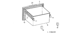
ここで、図3及び図4は、野菜室扉3と野菜室用の貯蔵品容器8とを示している。この図3及び図4で明らかなように、野菜室扉3は裏面の左右両側に例えば金属製の堅牢な容器支持部材9を有しており、これに野菜室用の貯蔵品容器8を収納して掛け、かくして、野菜室扉3と野菜室用の貯蔵品容器8とを容器支持部材9を介して一体化している。又、野菜室扉3の裏面の周縁部には、図示しない永久磁石を内蔵したガスケット10を取付けている。
Here, FIG.3 and FIG.4 has shown the
そして、容器支持部材9のそれぞれ後方に指向する後端には、図5にも示すように、永久磁石11を取付けている。これに対して、12は永久磁石11と対応する電磁装置、この場合、電磁石を示しており、この電磁石12は、図6に示すように、冷蔵庫本体1における内箱13の野菜室7を囲繞形成する部分の奥部左右両側に配設しており(左側のもののみ図示)、すなわち、野菜室7の奥部の左右両側に配設していて、要するに冷蔵庫本体1に設けている。
And as shown also in FIG. 5, the
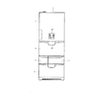
電磁石12は、詳細には図1に示すように、例えばコ字形のコア14と、これの上辺部と下辺部とにそれぞれボビン15,16を介して巻装したコイル17,18とを、ケース19に収納して構成しており、コア14の上辺部前端と下辺部前端とがそれぞれN,Sの磁極として機能するようになっている。又、この電磁石12は、コイル17,18に印加する電圧を変えることにより、磁力の調整をすることを可能としており、前記冷蔵庫本体1における冷蔵室扉2の前面部には、その調整操作をするための操作部である操作パネル20を図2に示すように有している。
In detail, as shown in FIG. 1, the
しかして、内箱13の野菜室7を囲繞形成した部分の左右両側面部には、それぞれレール21を形成しており(図1及び図6に左側面部のもののみ図示)、これに、容器支持部材9の後端部下側に設けた脚車22を転動可能に載置し、一方、レール21の前部には受車(図示せず)を設けていて、これに容器支持部材9を相対的に転動可能に載置し、かくして、容器支持部材9、ひいては野菜室用の貯蔵品容器8を、レール21により案内する形態で野菜室7に前後に出し入れ可能に収納し、前述の引出し式としている。又、その結果、野菜室扉3も前述の引出し式となっている。
Thus,
ここで、レール21は、後端部21aが後下がりに傾斜しており、ここに容器支持部材9が脚車22ごと落ち込んで係止されることにより、野菜室用の貯蔵品容器8を最奥側の収納位置に留めるようにしており、これを「落とし込み」構造と称している。
又、野菜室用の貯蔵品容器8が上述の収納位置にあるとき、前記電磁石12のコア14の上辺部前端と下辺部前端すなわち磁極部分に、前記永久磁石11の磁極部分が対向して当接するようにしている。
Here, the
Further, when the
以上に対して、図7には、野菜室扉3の上辺部前面側の中央部に設けた引出し用の取手23と凹部24、及び支持台25を示している。そのうち、支持台25を野菜室扉3に図1に示すように組み込んでおり、この支持台25が有する支軸26によって断面逆L字形の取手23を前後に回動可能に支持している。
In contrast to this, FIG. 7 shows the pull-out
又、支持台25は操作応動機構27を構成するものでもあり、この操作応動機構27は、支持台25に図7に示す軸28によって平面L字形のレバー29を前後に回動可能に枢支して成り、レバー29は、上記取手23の上部後端23aと対応する箇所に受け部29aを有し、後端部に永久磁石30を取付けて、それを野菜室扉3の後方に突出させている。
The
そして、図7及び図1には又、前記冷蔵庫本体1における野菜室7の貯蔵品出入口7aとその上方の冷蔵室の貯蔵品出入口との間を仕切る前仕切板31を示しており、これに検知器32を組み込んでいる。この検知器32は、この場合、リードスイッチから成っており、これに上記レバー29に取付けた永久磁石30を透磁膜33を介して対応させている。
なお、図示しないが、冷蔵庫本体1には、上記検知器32から出力される検知信号等に基づき、前記電磁石12に通電する働きをするマイクロコンピュータ等の制御装置を設けている。
FIG. 7 and FIG. 1 also show a
Although not shown, the refrigerator
次に、上記構成のものの作用を述べる。
まず、野菜室扉3を閉鎖した状態にあるとき、容器支持部材9の脚車22は、前述の「落とし込み」構造によって最奥側の収納位置に留められている。又、このとき、図示しない制御装置も、電磁石12を、コア14の上辺部前端と下辺部前端の各磁極に、対応する永久磁石11の磁極と異なる極が表れるように通電して励起させている。従って、それら電磁石12と永久磁石11との間には吸引力が生じており、それによって、永久磁石11が、ひいては容器支持部材9が後方へ引き寄せられ、これによっても、容器支持部材9、ひいては野菜室用の貯蔵品容器8は、最奥側の収納位置に留められている。
Next, the operation of the above configuration will be described.
First, when the
更に、このときには、野菜室扉3のガスケット10が、冷蔵庫本体1における野菜室7の貯蔵品出入口7aの周縁部(前仕切板31を含む)に密接すると共に、内蔵したマグネットによりその密接状態に吸着保持されている。
Further, at this time, the
さて、このような状態から、使用者が野菜室扉3の取手23に手を掛けて引くと、取手23は支軸26を中心に図1に矢印Aで示すように前方へ回動し、上部後端23aによって操作応動機構27におけるレバー29の受け部29aを後方へ押圧する。これにより、図1及び図7に矢印Bで示すように、レバー29が軸28を中心に後方へ回動し、後端部に取付けた永久磁石30を検知器32に近接させるから、検知器32が作動し、それに基づいて、図示しない制御装置が電磁石12を前述とは反対の方向に通電して励起させる。
Now, from this state, when the user puts his hand on the
従って、このとき、電磁石12は、コア14の上辺部前端と下辺部前端の各磁極に、対応する永久磁石11の磁極と同じ極を表し、それによる反発力が生じる。それによって、永久磁石11が、ひいてはそれを後端部に取付けた容器支持部材9が、野菜室用の貯蔵品容器8と野菜室扉3とを伴って前方へ押し出される。この押し出しにより、脚車22は前述の「落とし込み」構造から脱し、ガスケット10が野菜室7の貯蔵品出入口の周縁部から離間する。
よって、その後には、使用者が取手23に掛けた手で野菜室扉3を引き続けることにより、野菜室扉3と一体に貯蔵品容器8を所望に引き出すことができる。
Therefore, at this time, the
Therefore, after that, the stored
そして、上述のように機能させるのに、本構成のものにおいては、電磁石12や検知器32という電気部品は冷蔵庫本体1にのみ設け、野菜室扉3側には取手23や操作応動機構27という機械部品しか設けていない。よって、冷蔵庫本体1に枢支された部分が存在しない引出し式の野菜室扉3においても、野菜室扉3側の電気部品と冷蔵庫本体1側の電気部品との接続に苦慮することなく、上述の電磁石12による所望の開放機能もしくは開放補助機能を持たせることができる。
And in order to make it function as mentioned above, in the thing of this composition, electric parts called
又、この場合、野菜室扉3側の電気部品と冷蔵庫本体1側の電気部品との接続をする必要がないことにより、その接続用のリード線並びに接続作業の廃止等もできて、コストの低減化に寄与できる。
Moreover, in this case, since it is not necessary to connect the electrical component on the
加えて、本構成のものの場合、電磁石12が、野菜室扉3引出し時以外の常時は、野菜室扉3を冷蔵庫本体1側に寄せて、貯蔵品容器8を収納位置に留めるようにしており、これによって、野菜室扉3を閉鎖状態に一段と確実に留めることができ、貯蔵品容器8を収納位置に一段と確実に留めることができる。
In addition, in the case of this configuration, the
更に、本構成のものの場合、電磁石12が野菜室扉3を冷蔵庫本体1から離間させる磁力の調整を可能としており、これによって、使用者が野菜室扉3を開けようとする(貯蔵品容器8を引き出そうとする)ときの軽重の感覚(貯蔵品容器8に入れた貯蔵品の総質量によって異なる)に応じて、電磁石12による最適の開放力を得ることができる。
なお、この場合、貯蔵品容器8の重量を重量センサ等により検知して、電磁石12が野菜室扉3を冷蔵庫本体1から離間させる磁力を自動的に調整するようにしても良い。
Further, in the case of this configuration, the
In this case, the weight of the
以上に対して、図8ないし図10は本発明の第2及び第3実施例(第2及び第3の実施形態)を示すもので、第1実施例と同一の部分には同一の符号を付して説明を省略し、異なる部分についてのみ述べる。 8 to 10 show the second and third examples (second and third embodiments) of the present invention, and the same parts as those in the first example are denoted by the same reference numerals. A description will be omitted, and only different parts will be described.
[第2実施例]
図8に示す第2実施例においては、レール21の後端部21bを、前述の後端部21aのような傾斜をしないものとして、レール21の全部を同じ高さの平坦状に形成しており、すなわち、前述の「落とし込み」部分を有さないようにしている。
[Second Embodiment]
In the second embodiment shown in FIG. 8, the
前述のように、電磁石12が、野菜室扉3引出し時以外の常時は、野菜室扉3を冷蔵庫本体1側に寄せて、貯蔵品容器8を収納位置に留めるようにした構成においては、それによって野菜室扉3を閉鎖状態に一段と確実に留めることができ、貯蔵品容器8を収納位置に一段と確実に留めることができるので、このように、貯蔵品容器8を出し入れ可能に案内するレール21に、貯蔵品容器8を収納位置に落とし込む部分を有さない構造とすることにより、それに抗して使用者が野菜室扉3(貯蔵品容器8)を引出す必要がなくなるので、使用者の労力の軽減が一層できる。
As described above, in the configuration in which the
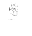
[第3実施例]
図9及び図10に示す第3実施例においては、永久磁石ユニット41を、前述の永久磁石11に代えて、野菜室扉3の裏面の左右両側部又はその一方側に設け、電磁石12を、冷蔵庫本体1における内箱13の野菜室7を囲繞形成する部分の左右両内側面部の前部又はその一方側の前部に設けている。
又、永久磁石ユニット41は、鉄など磁性体から成るヨーク42の上下の両端に、永久磁石43,44を取付け、それらをケース45に収納して構成している。
このようにしても、前述同様の作用効果を得ることができる。
[Third embodiment]
In the third embodiment shown in FIGS. 9 and 10, the
The
Even if it does in this way, the effect similar to the above-mentioned can be acquired.
なお、このほか、電磁石12で例示した電磁装置は、永久磁石11との反発磁力で野菜室扉3を押し出すものに限られず、例えば可動のコアを有して、それにより野菜室扉3を押し出すものであっても良い。
又、そのような押し出し部品を使用するならば、電磁装置は電磁石12以外に例えばモータ等を使用しても良い。
更に、検知器32はマイクロスイッチであっても良い。
In addition, the electromagnetic device illustrated by the
If such an extruded part is used, the electromagnetic device may use, for example, a motor in addition to the
Further, the
そして、貯蔵庫の全体としては、冷蔵庫以外に温蔵庫、常温庫等であっても良い。
加えて、野菜室扉3で例示した引き出し式の扉は、野菜室扉3以外に製氷室扉4や切換室扉5及び冷凍室扉6等であっても良い。
そのほか、本発明は上記し且つ図面に示した実施例にのみ限定されるものではなく、要旨を逸脱しない範囲内で適宜変更して実施し得る。
And as a whole storage, a warm storage, a normal temperature storage, etc. other than a refrigerator may be sufficient.
In addition, the drawer-type door illustrated as the
In addition, the present invention is not limited to the embodiments described above and shown in the drawings, and can be implemented with appropriate modifications without departing from the scope of the invention.
図面中、1は冷蔵庫本体(貯蔵庫本体)、3は野菜室扉(扉)、7は野菜室(貯蔵室)、7aは貯蔵品出入口、8は貯蔵品容器、9は容器支持部材、11は永久磁石、12は電磁石(電磁装置)、27は操作応動機構、29はレバー、32は検知器、41は永久磁石ユニットを示す。 In the drawings, 1 is a refrigerator body (storage body), 3 is a vegetable room door (door), 7 is a vegetable room (storage room), 7a is a storage product entrance, 8 is a storage product container, 9 is a container support member, and 11 is a container support member. A permanent magnet, 12 is an electromagnet (electromagnetic device), 27 is an operation responsive mechanism, 29 is a lever, 32 is a detector, and 41 is a permanent magnet unit.
Claims (6)
前記貯蔵室の貯蔵品出入口を開閉する扉と、
この扉の移動に伴う引出し動作にて前記貯蔵室に出し入れされる貯蔵品容器と、
前記扉に設けられ、使用者の操作により、レバーが後方へ押圧される操作応動機構と、
前記貯蔵庫本体に設けられた電磁装置、及び検知器とを具備し、
前記レバーが後方へ押圧されることにより前記検知器を作動させ、この検知器の作動に基づき前記電磁装置が励起されて、前記扉を貯蔵庫本体から離間させるようにしたことを特徴とする貯蔵庫。 A storage body having a storage room;
A door that opens and closes the storage item entrance of the storage room;
A storage container to be taken in and out of the storage chamber by a pulling operation accompanying the movement of the door,
An operation responsive mechanism that is provided on the door and is pressed backward by a user operation;
Comprising an electromagnetic device and a detector provided in the storage body;
The storage is characterized in that the lever is pressed backward to operate the detector, and the electromagnetic device is excited based on the operation of the detector to separate the door from the storage body.
Priority Applications (1)
| Application Number | Priority Date | Filing Date | Title |
|---|---|---|---|
| JP2007173984A JP4091649B2 (en) | 2007-07-02 | 2007-07-02 | Storage |
Applications Claiming Priority (1)
| Application Number | Priority Date | Filing Date | Title |
|---|---|---|---|
| JP2007173984A JP4091649B2 (en) | 2007-07-02 | 2007-07-02 | Storage |
Related Parent Applications (1)
| Application Number | Title | Priority Date | Filing Date |
|---|---|---|---|
| JP2005129699A Division JP4091614B2 (en) | 2005-04-27 | 2005-04-27 | Storage |
Publications (2)
| Publication Number | Publication Date |
|---|---|
| JP2007285698A true JP2007285698A (en) | 2007-11-01 |
| JP4091649B2 JP4091649B2 (en) | 2008-05-28 |
Family
ID=38757634
Family Applications (1)
| Application Number | Title | Priority Date | Filing Date |
|---|---|---|---|
| JP2007173984A Active JP4091649B2 (en) | 2007-07-02 | 2007-07-02 | Storage |
Country Status (1)
| Country | Link |
|---|---|
| JP (1) | JP4091649B2 (en) |
Cited By (3)
| Publication number | Priority date | Publication date | Assignee | Title |
|---|---|---|---|---|
| CN103017440A (en) * | 2013-01-10 | 2013-04-03 | 合肥美的荣事达电冰箱有限公司 | Refrigerator |
| CN104344659A (en) * | 2013-09-25 | 2015-02-11 | 海尔集团公司 | Movable power-assisted handle device for door body of refrigerator and door body |
| WO2018116673A1 (en) * | 2016-12-21 | 2018-06-28 | パナソニックIpマネジメント株式会社 | Refrigerator |
Citations (7)
| Publication number | Priority date | Publication date | Assignee | Title |
|---|---|---|---|---|
| JPH01222187A (en) * | 1988-02-29 | 1989-09-05 | Toshiba Corp | Storage box |
| JPH01136383U (en) * | 1988-02-25 | 1989-09-19 | ||
| JPH09189481A (en) * | 1996-01-09 | 1997-07-22 | Hitachi Ltd | Storage chamber with drawer type door |
| JP2000291333A (en) * | 1999-04-07 | 2000-10-17 | Sankyo Seiki Mfg Co Ltd | Operation support device |
| JP2001050645A (en) * | 1999-08-06 | 2001-02-23 | Toshiba Corp | Door device for storage cabinet |
| JP2005011773A (en) * | 2003-06-20 | 2005-01-13 | Toshiba Corp | Touch switch device and refrigerator equipped with the same |
| JP2005098558A (en) * | 2003-09-22 | 2005-04-14 | Toshiba Corp | Refrigerator |
-
2007
- 2007-07-02 JP JP2007173984A patent/JP4091649B2/en active Active
Patent Citations (7)
| Publication number | Priority date | Publication date | Assignee | Title |
|---|---|---|---|---|
| JPH01136383U (en) * | 1988-02-25 | 1989-09-19 | ||
| JPH01222187A (en) * | 1988-02-29 | 1989-09-05 | Toshiba Corp | Storage box |
| JPH09189481A (en) * | 1996-01-09 | 1997-07-22 | Hitachi Ltd | Storage chamber with drawer type door |
| JP2000291333A (en) * | 1999-04-07 | 2000-10-17 | Sankyo Seiki Mfg Co Ltd | Operation support device |
| JP2001050645A (en) * | 1999-08-06 | 2001-02-23 | Toshiba Corp | Door device for storage cabinet |
| JP2005011773A (en) * | 2003-06-20 | 2005-01-13 | Toshiba Corp | Touch switch device and refrigerator equipped with the same |
| JP2005098558A (en) * | 2003-09-22 | 2005-04-14 | Toshiba Corp | Refrigerator |
Cited By (7)
| Publication number | Priority date | Publication date | Assignee | Title |
|---|---|---|---|---|
| CN103017440A (en) * | 2013-01-10 | 2013-04-03 | 合肥美的荣事达电冰箱有限公司 | Refrigerator |
| CN104344659A (en) * | 2013-09-25 | 2015-02-11 | 海尔集团公司 | Movable power-assisted handle device for door body of refrigerator and door body |
| WO2015043479A1 (en) * | 2013-09-25 | 2015-04-02 | 海尔集团公司 | Movable assist handle apparatus for door body of refrigerator and door body |
| CN104344659B (en) * | 2013-09-25 | 2017-01-18 | 海尔集团公司 | Movable power-assisted handle device for door body of refrigerator and door body |
| WO2018116673A1 (en) * | 2016-12-21 | 2018-06-28 | パナソニックIpマネジメント株式会社 | Refrigerator |
| JPWO2018116673A1 (en) * | 2016-12-21 | 2019-10-24 | パナソニックIpマネジメント株式会社 | refrigerator |
| JP7016000B2 (en) | 2016-12-21 | 2022-02-04 | パナソニックIpマネジメント株式会社 | refrigerator |
Also Published As
| Publication number | Publication date |
|---|---|
| JP4091649B2 (en) | 2008-05-28 |
Similar Documents
| Publication | Publication Date | Title |
|---|---|---|
| JP4091614B2 (en) | Storage | |
| KR101618129B1 (en) | Refrigerator | |
| JP4247278B2 (en) | refrigerator | |
| JP2006250485A (en) | Refrigerator door device | |
| JP4384187B2 (en) | refrigerator | |
| KR102338468B1 (en) | Refrigerator | |
| JP4091649B2 (en) | Storage | |
| JP2008008550A (en) | Door opening and closing device | |
| JP4477646B2 (en) | refrigerator | |
| JP4366410B2 (en) | refrigerator | |
| JP2009144931A (en) | Refrigerator | |
| US7607742B2 (en) | Refrigerator having basket lift apparatus | |
| JP6706734B2 (en) | refrigerator | |
| JP2007298272A (en) | Storage box | |
| JP2002267352A (en) | Refrigerator | |
| JP4054337B2 (en) | Storage | |
| JP2004323043A (en) | Article storage chamber | |
| JP2008196753A (en) | Refrigerator | |
| JP4203041B2 (en) | Storage | |
| KR100797219B1 (en) | Reservoir | |
| JP4054363B2 (en) | Storage | |
| US20100300136A1 (en) | Domestic appliance with telescopic pull-out means | |
| JP4298773B2 (en) | Storage | |
| JP2009121742A (en) | Refrigerator | |
| JP2006308169A (en) | Cold storage |
Legal Events
| Date | Code | Title | Description |
|---|---|---|---|
| A871 | Explanation of circumstances concerning accelerated examination |
Free format text: JAPANESE INTERMEDIATE CODE: A871 Effective date: 20070806 |
|
| A975 | Report on accelerated examination |
Free format text: JAPANESE INTERMEDIATE CODE: A971005 Effective date: 20070815 |
|
| A131 | Notification of reasons for refusal |
Free format text: JAPANESE INTERMEDIATE CODE: A131 Effective date: 20070904 |
|
| A521 | Written amendment |
Free format text: JAPANESE INTERMEDIATE CODE: A523 Effective date: 20071031 |
|
| A131 | Notification of reasons for refusal |
Free format text: JAPANESE INTERMEDIATE CODE: A131 Effective date: 20071204 |
|
| A521 | Written amendment |
Free format text: JAPANESE INTERMEDIATE CODE: A523 Effective date: 20080129 |
|
| TRDD | Decision of grant or rejection written | ||
| A01 | Written decision to grant a patent or to grant a registration (utility model) |
Free format text: JAPANESE INTERMEDIATE CODE: A01 Effective date: 20080219 |
|
| A61 | First payment of annual fees (during grant procedure) |
Free format text: JAPANESE INTERMEDIATE CODE: A61 Effective date: 20080228 |
|
| R150 | Certificate of patent or registration of utility model |
Ref document number: 4091649 Country of ref document: JP Free format text: JAPANESE INTERMEDIATE CODE: R150 Free format text: JAPANESE INTERMEDIATE CODE: R150 |
|
| FPAY | Renewal fee payment (event date is renewal date of database) |
Free format text: PAYMENT UNTIL: 20110307 Year of fee payment: 3 |
|
| FPAY | Renewal fee payment (event date is renewal date of database) |
Free format text: PAYMENT UNTIL: 20110307 Year of fee payment: 3 |
|
| S533 | Written request for registration of change of name |
Free format text: JAPANESE INTERMEDIATE CODE: R313533 |
|
| R350 | Written notification of registration of transfer |
Free format text: JAPANESE INTERMEDIATE CODE: R350 |
|
| R350 | Written notification of registration of transfer |
Free format text: JAPANESE INTERMEDIATE CODE: R350 |
|
| FPAY | Renewal fee payment (event date is renewal date of database) |
Free format text: PAYMENT UNTIL: 20110307 Year of fee payment: 3 |
|
| FPAY | Renewal fee payment (event date is renewal date of database) |
Free format text: PAYMENT UNTIL: 20120307 Year of fee payment: 4 |
|
| FPAY | Renewal fee payment (event date is renewal date of database) |
Free format text: PAYMENT UNTIL: 20130307 Year of fee payment: 5 |
|
| FPAY | Renewal fee payment (event date is renewal date of database) |
Free format text: PAYMENT UNTIL: 20140307 Year of fee payment: 6 |
|
| S111 | Request for change of ownership or part of ownership |
Free format text: JAPANESE INTERMEDIATE CODE: R313117 Free format text: JAPANESE INTERMEDIATE CODE: R313115 |
|
| S531 | Written request for registration of change of domicile |
Free format text: JAPANESE INTERMEDIATE CODE: R313531 |
|
| S533 | Written request for registration of change of name |
Free format text: JAPANESE INTERMEDIATE CODE: R313533 |
|
| R350 | Written notification of registration of transfer |
Free format text: JAPANESE INTERMEDIATE CODE: R350 |