JP2007274832A - Power supply apparatus, and control method of power supply apparatus - Google Patents
Power supply apparatus, and control method of power supply apparatus Download PDFInfo
- Publication number
- JP2007274832A JP2007274832A JP2006098698A JP2006098698A JP2007274832A JP 2007274832 A JP2007274832 A JP 2007274832A JP 2006098698 A JP2006098698 A JP 2006098698A JP 2006098698 A JP2006098698 A JP 2006098698A JP 2007274832 A JP2007274832 A JP 2007274832A
- Authority
- JP
- Japan
- Prior art keywords
- power
- switch
- power supply
- storage means
- power storage
- Prior art date
- Legal status (The legal status is an assumption and is not a legal conclusion. Google has not performed a legal analysis and makes no representation as to the accuracy of the status listed.)
- Pending
Links
Images


Classifications
-
- Y—GENERAL TAGGING OF NEW TECHNOLOGICAL DEVELOPMENTS; GENERAL TAGGING OF CROSS-SECTIONAL TECHNOLOGIES SPANNING OVER SEVERAL SECTIONS OF THE IPC; TECHNICAL SUBJECTS COVERED BY FORMER USPC CROSS-REFERENCE ART COLLECTIONS [XRACs] AND DIGESTS
- Y02—TECHNOLOGIES OR APPLICATIONS FOR MITIGATION OR ADAPTATION AGAINST CLIMATE CHANGE
- Y02E—REDUCTION OF GREENHOUSE GAS [GHG] EMISSIONS, RELATED TO ENERGY GENERATION, TRANSMISSION OR DISTRIBUTION
- Y02E60/00—Enabling technologies; Technologies with a potential or indirect contribution to GHG emissions mitigation
- Y02E60/10—Energy storage using batteries
-
- Y—GENERAL TAGGING OF NEW TECHNOLOGICAL DEVELOPMENTS; GENERAL TAGGING OF CROSS-SECTIONAL TECHNOLOGIES SPANNING OVER SEVERAL SECTIONS OF THE IPC; TECHNICAL SUBJECTS COVERED BY FORMER USPC CROSS-REFERENCE ART COLLECTIONS [XRACs] AND DIGESTS
- Y02—TECHNOLOGIES OR APPLICATIONS FOR MITIGATION OR ADAPTATION AGAINST CLIMATE CHANGE
- Y02T—CLIMATE CHANGE MITIGATION TECHNOLOGIES RELATED TO TRANSPORTATION
- Y02T10/00—Road transport of goods or passengers
- Y02T10/60—Other road transportation technologies with climate change mitigation effect
- Y02T10/70—Energy storage systems for electromobility, e.g. batteries
-
- Y—GENERAL TAGGING OF NEW TECHNOLOGICAL DEVELOPMENTS; GENERAL TAGGING OF CROSS-SECTIONAL TECHNOLOGIES SPANNING OVER SEVERAL SECTIONS OF THE IPC; TECHNICAL SUBJECTS COVERED BY FORMER USPC CROSS-REFERENCE ART COLLECTIONS [XRACs] AND DIGESTS
- Y02—TECHNOLOGIES OR APPLICATIONS FOR MITIGATION OR ADAPTATION AGAINST CLIMATE CHANGE
- Y02T—CLIMATE CHANGE MITIGATION TECHNOLOGIES RELATED TO TRANSPORTATION
- Y02T10/00—Road transport of goods or passengers
- Y02T10/60—Other road transportation technologies with climate change mitigation effect
- Y02T10/72—Electric energy management in electromobility
Abstract
Description
本発明は、電力供給装置及び電力供給装置の制御方法に関する。 The present invention relates to a power supply apparatus and a control method for the power supply apparatus.
電気自動車には、車両駆動用のモータに電気的に接続可能な複数の蓄電手段を有する車両用電力供給装置が組み込まれている(特許文献1参照)。特許文献1に開示された車両用電力供給装置は、複数の蓄電手段を直列接続又は並列接続に切り換えることが可能に構成され、複数の蓄電手段の直並列を切り換えることによって、複数の蓄電手段からの出力電圧を変化させている。具体的には、要求される印加電圧が小さい場合には、複数の蓄電手段を並列接続して出力電圧を小さくし、要求される印加電圧が大きい場合には、複数の蓄電手段を直列接続して出力電圧を大きくしている。
ところが、複数の蓄電手段を用いるため、蓄電手段間に電力容量のばらつきが生じる場合がある。そこで、蓄電手段の電力容量調整を行う必要があった。 However, since a plurality of power storage means are used, there may be variations in power capacity between the power storage means. Therefore, it is necessary to adjust the power capacity of the power storage means.
本発明は、特にイグニッションキーがオフした状態において、蓄電手段の電力容量調整を可能とする電力供給装置を提供することを目的とする。 An object of the present invention is to provide a power supply device that can adjust the power capacity of a power storage means, particularly in a state where an ignition key is turned off.
上記目的を達成するための請求項1に記載の発明は、車両駆動用電動機に接続されたインバータに電力を供給する複数の蓄電手段と、
前記複数の蓄電手段から前記インバータに電力を供給するための回路に配置され、イグニッションキーがオフされたときに前記複数の蓄電手段から前記インバータへの電力の供給を遮断する第1のスイッチ手段と、
前記複数の蓄電手段同士を並列接続するための回路に配置され、前記複数の蓄電手段同士を並列接続することによって前記複数の蓄電手段のそれぞれを容量自己調整させる第2のスイッチ手段と、
車両に搭載された補機に電力を供給する補機用電源と、
前記第2のスイッチ手段によって並列接続された前記複数の蓄電手段の電力を変換し出力する電力変換器と、
前記補機用電源および/または前記電力変換器からの電力供給により、前記第2のスイッチ手段および前記電力変換器を駆動するスイッチ駆動手段と、
前記スイッチ駆動手段の作動を制御し、前記イグニッションキーがオフされ前記第1のスイッチ手段により、前記複数の蓄電手段から前記車両駆動用電動機への電力の供給を遮断されているとき、前記補機用電源からの電力供給により前記第2のスイッチ手段を駆動させて前記複数の蓄電手段を並列接続するとともに、前記電力変換器からの電力供給によって前記第2のスイッチ手段を駆動する制御手段とを有する電力供給装置である。
The invention according to
A first switch means disposed in a circuit for supplying power from the plurality of power storage means to the inverter, and shuts off the power supply from the plurality of power storage means to the inverter when an ignition key is turned off; ,
A second switch means disposed in a circuit for connecting the plurality of power storage means in parallel, and self-adjusting the capacity of each of the plurality of power storage means by connecting the plurality of power storage means in parallel;
An auxiliary power supply for supplying power to the auxiliary equipment mounted on the vehicle;
A power converter that converts and outputs power of the plurality of power storage means connected in parallel by the second switch means;
Switch driving means for driving the second switch means and the power converter by supplying power from the auxiliary power source and / or the power converter;
When the operation of the switch driving means is controlled, the ignition key is turned off, and the supply of power from the plurality of power storage means to the vehicle driving motor is interrupted by the first switch means, the auxiliary machine Control means for driving the second switch means in parallel by driving the second switch means by supplying power from a power source and driving the second switch means by supplying power from the power converter. It is the electric power supply apparatus which has.
本発明によれば、並列接続する複数の蓄電手段の電力を調整し、複数の蓄電手段の接続を切り換えるスイッチを駆動する駆動手段に電力を供給する電力変換器を備えることで、イグニッションキーがオフした状態において、一旦補助電源からの電力供給により複数の蓄電手段を接続してしまえば、その後電力変換器によりスイッチにスイッチ駆動用電力を複数の蓄電手段から供給することが可能となり、補助電源からの電力供給によらず、蓄電手段の容量調整を終了することを可能とし、もって、複数の蓄電手段の電力容量調整を可能とする。 According to the present invention, the ignition key is turned off by providing the power converter that adjusts the power of the plurality of power storage means connected in parallel and supplies power to the drive means that drives the switch that switches the connection of the plurality of power storage means. In this state, once a plurality of power storage means are connected by supplying power from the auxiliary power supply, it becomes possible to supply switch driving power to the switch from the plurality of power storage means by the power converter. Regardless of the power supply, the capacity adjustment of the power storage means can be ended, and thus the power capacity adjustment of a plurality of power storage means can be performed.
以下、本発明に係る電力供給装置及び電力供給装置の制御方法を図面を参照しつつ説明する。 Hereinafter, a power supply device and a method for controlling the power supply device according to the present invention will be described with reference to the drawings.
図1に、本発明における電力供給装置を、図2及び図3に、電力供給装置の制御方法のフローチャートを、図4〜図6に、前記フローチャートにおける電力供給装置の蓄電手段の種々の接続状態を示す。 FIG. 1 shows a power supply apparatus according to the present invention, FIGS. 2 and 3 show flowcharts of a control method of the power supply apparatus, and FIGS. 4 to 6 show various connection states of power storage means of the power supply apparatus in the flowcharts. Indicates.
図1は、本発明に係る車両の概略、及び電力供給装置1(電力供給装置に相当する)の構成を示す図である。電力供給装置1は、複数の電池1a、1b(複数の蓄電手段に相当する)と、充電抵抗2と、電池1a、1b及び充電抵抗2の接続を切り換える複数のスイッチSW1〜5(第2のスイッチ手段に相当する)とを有する回路部1αと、回路部1αの出力端に接続するDCDCコンバータ3(電力変換器に相当する)をさらに有する回路部1βと、回路部1βのスイッチSW1〜5及びDCDCコンバータ3を駆動するスイッチドライブ回路6b(スイッチ駆動手段に相当する)と、スイッチドライブ回路6bに電力を供給するバッテリ4(補機用電源に相当する)及びバッテリ4とスイッチドライブ回路6bとの接続を切り換えるリレースイッチSW7(第3のスイッチ手段に相当する)と、イグニッション(IGN)キー13からの指令を受け、スイッチドライブ回路6bの作動を制御するコントローラ6a(制御手段に相当する)とを有する。なお、DCDCコンバータ3はバッテリ4と同様にスイッチドライブ回路6bに接続し、スイッチドライブ回路6bへ電力を供給することができる。またDCDCコンバータ3はバッテリ4と接続し、DCDCコンバータ3とバッテリ4とを接続する経路上から、スイッチドライブ回路6bへ接続する回路が設けられていることにより、バッテリ4及びDCDCコンバータ3派スイッチドライブ回路6bと接続する。ただし、DCDCコンバータ3とバッテリ4とを繋ぐ回路上には、DCDCコンバータ3からバッテリ4の方向の一方向のみ通電可能なダイオードなどが設けられている。これにより、DCDCコンバータ3は、電池1a、1bからスイッチドライブ回路6bの方向のみ電力変換が可能となる。さらに、バッテリ4とリレースイッチSW7との間には電流センサS5が接続する。そしてさらに、電力供給装置1は上述する構成を有する回路部1βの出力端に、電池1a、1bからの出力を遮断するコンダクタスイッチSW6(第1のスイッチに相当する)を介してインバータ7と接続し、モータ8(車両駆動用電動機に相当する)、変速機9及び差動歯車10を介し車輪11,12を駆動する。なお、充電抵抗2部分には充電抵抗2の端子間電圧を測定する電圧測定器14が設けられている。また、コンダクタスイッチSW6及びリレースイッチSW7はイグニッションキー13に連動し、自然にオフするものとする。また、電池1a、1bは単一、または直列接続する複数の単位電池からなり、インバータ7を介してモータ8に電気的に直並列接続可能な二次電池である。
FIG. 1 is a diagram showing an outline of a vehicle according to the present invention and a configuration of a power supply device 1 (corresponding to a power supply device). The
次に、図1に示す電力供給装置1の電池1a、1b及びスイッチSW1〜5からなる回路部分1αの構成を詳細に説明する。
Next, the configuration of the circuit portion 1α including the
スイッチSW1は、電池1aの正極と電池1bの負極とをつなぐ経路上に配置され、電池1aの正極とスイッチSW1との間に充電抵抗2が配置されている。また、スイッチSW2は電池1aの正極と充電抵抗2をつなぐ経路上から電池1bの負極へとつながる経路上に配置されている。
The switch SW1 is disposed on a path connecting the positive electrode of the
さらにスイッチSW3は、充電抵抗2とスイッチSW1とをつなぐ経路上からインバータ7の正極(以降、インバータ7の接続部であって、電池の正極と接続する側をインバータの正極とし、また負極と接続する側をインバータの負極と称して説明する)へとつながる経路上に配置されている。 Further, the switch SW3 is connected to the positive electrode of the inverter 7 from the path connecting the charging resistor 2 and the switch SW1 (hereinafter referred to as a connecting portion of the inverter 7 and connected to the positive electrode of the battery, and connected to the negative electrode of the inverter). (This will be referred to as the negative electrode of the inverter).
さらにまた、スイッチSW4は電池1aの正極とインバータ7の正極とをつなぐ経路上に配置され、スイッチSW5は電池1bの負極とインバータ7の負極とをつなぐ経路上に配置されている。
Furthermore, the switch SW4 is arranged on a path connecting the positive electrode of the
これにより、スイッチSW1のみをオンするとインバータ7に対し、電池1aと電池1bが充電抵抗2を介して直列接続する経路を形成し、また、スイッチSW2のみをオンすると、インバータ7に対し、電池1aと電池1bが充電抵抗2を介さずに直列接続する経路を形成する。さらにまた、スイッチSW3のみをオンすると電池1aが充電抵抗2を介してインバータ7と接続する経路を形成し、スイッチSW4のみをオンすると電池1aが充電抵抗2を介さずにインバータ7と接続する経路を形成する。さらにまた、スイッチSW5のみをオンすると、インバータ7に対し、電池1bのみが接続する経路を形成する。
Thus, when only the switch SW1 is turned on, a path in which the
なお、本実施形態においては、主としてスイッチSW3、5をオンし、電池1aと電池1bとが充電抵抗2を介して並列に接続する状態を用いる。また、DCDCコンバータ3は上述するように回路部1αの出力端であって、複数の電池1a、1bが充電抵抗2を介して並列接続するとき、スイッチSW3及びSW5を介して複数の電池1a、1bと接続する。このように接続することにより、DCDCコンバータ3は複数の電池1a、1bが並列接続するときに限り、複数の電池1a、1bと接続する。
In the present embodiment, a state in which the switches SW3 and SW5 are mainly turned on and the
次に、図2のフローチャートに沿って、電力供給装置1の制御方法を説明する。
Next, a control method of the
なお、本実施形態は、イグニッションキー13を切り、コンダクタスイッチSW6が遮断状態となり電池1a、1bからモータ8への電力供給が遮断された後の、電池容量を調整する制御方法である。なお、フローチャート中の「t1」及び「t2」の記載は、一般的にイグニッションキー13がオフされた後に、コンダクタSW6がオフする時間(t1)及びリレースイッチSW7がオフする時間(t2)を表すもので、この数字は予め設定されているものである。ただし、必ずコンダクタスイッチSW6が先にオフするものとする(t1<t2)。本実施形態における制御方法をあらわすフローは、この、コンダクタスイッチSW6及びリレースイッチSW7がイグニッションキー13オフ後自然オフするまでの時間内に、各ステップを終了するものである。
This embodiment is a control method for adjusting the battery capacity after the ignition key 13 is turned off and the conductor switch SW6 is cut off and the power supply from the
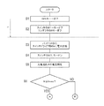
まず、イグニッションキー13がオフされると(ステップS1(以下、ステップSを「S」と省略する))、それに伴い、スイッチSW1〜SW5及びコンダクタスイッチSW6がオフする(S2)。そして、電池1a、1bが完全にインバータ7と遮断された後、バッテリ4からの電力供給によって(S3)、スイッチSW3、5をオンし(S4)、電池1aと電池1bとを充電抵抗2を介して並列に接続させる(図4参照)。そして、このときの充電抵抗2にかかる電圧を測定し(S5)、電池1aと電池1bとの電位差及び充電抵抗2に流れる電流Irを算出する。そして、予め設定する上限電流Imax(所定値に相当する)と電流Irを比較する(S6)。ここでいう上限電流Imaxとは、ステップ4で形成される閉回路における電池1a、1bの電位差に起因する電流であって、接続する充電抵抗2によって異常(突入)電流を抑制可能な電流の上限である。なお、ここで設定する上限電流Imaxを超える電流が流れるほどの電位差が電池1a、1b間に生じているときに、以後の制御を行う(S6;NO)。
First, when the ignition key 13 is turned off (step S1 (hereinafter, step S is abbreviated as “S”)), the switches SW1 to SW5 and the conductor switch SW6 are turned off (S2). Then, after the
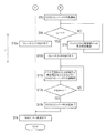
以後の制御を、図3に示す。なお、ステップS6;YESのときはAへ、ステップS6;NOのときはBへ進むものとする。 The subsequent control is shown in FIG. It should be noted that the process proceeds to A when YES in step S6; and to B when NO in step S6.
電流Irが上限電流Imax以下(S6;YES)のときは、この時点でリレースイッチSW7がオフする(S10a)。すなわち、電流Irが上限電流Imax以下(S6;YES)のときは、以後電力容量調整を要さないと判断する。リレースイッチSW7がオフされると、スイッチドライブ回路6bへの電力供給は遮断されるため、スイッチSW3及びスイッチSW5は自然オフし(S14)、元のスイッチ全オフ状態(S2)へ戻る。なお、ステップS6において、上限電流Imax以下で生じていた電池1a、1bの電位差による電流Irは、リレースイッチSW7オフ(S10a)後スイッチSW3、5が自然オフ(S14)するまでの間に、さらに容量自己調整を図り、低減される。
When the current Ir is equal to or lower than the upper limit current Imax (S6; YES), the relay switch SW7 is turned off at this time (S10a). That is, when the current Ir is equal to or lower than the upper limit current Imax (S6; YES), it is determined that power capacity adjustment is not required thereafter. When the relay switch SW7 is turned off, the power supply to the
一方、ステップ6において、電流Irが上限電流Imaxより大きい(S6;NO)ときは、バッテリ4からの電力供給によって並列に接続する電池1a、1bからの電力供給によりDCDCコンバータ3を作動させ(S7b)、バッテリ4とDCDCコンバータ3とによりスイッチドライブ回路6bへの電力供給を開始する(図5参照)。この状態で、電流センサ5における電流Isを測定し、電流Isが0になるまでバッテリ4からスイッチドライブ回路6bへの電力供給を継続する(S8b;NO→S9b→S8b)。そして、DCDCコンバータ3からの出力電圧がバッテリ4の出力電圧と等しくなり、電流センサS5に流れる電流Isが0になったとき、リレースイッチSW7がオフするようにし(S10b)、DCDCコンバータ3のみからスイッチドライブ回路6bへ電力を供給する状態にする(図6参照)。このとき、コントローラ6aは、リレースイッチSW7オフ後、DCDCコンバータ3からスイッチドライブ回路6bへの入力電圧が保証電圧(スイッチ駆動に必要な電圧)以上となるように、DCDCコンバータ3を作動させる(S11b)。これにより、以後の制御に関してはバッテリ4を使用せずに、DCDCコンバータ3のみでスイッチドライブ回路6bの駆動が可能となる。この状態で、改めて電流Irと上限電流Imaxとを比較し(S12b)、電流Irが上限電流Imax以下となるまで、DCDCコンバータ3を作動し続け、電池1a、1bの電位差を、容量自己調整によって低減させる(S12b;NO→S11b→S12b)。そして電流Irが上限電流Imax以下となったら(S12b;YES)、DCDCコンバータ3の作動を終了させる(S13b)。すると、スイッチドライブ回路6bへの電力供給はなくなり、スイッチSW3及びスイッチSW5は自然オフし(S14)、元のスイッチ全オフ状態(S2)へ戻る。なお、ステップS12bにおいて、上限電流Imax以下で生じていた電池1a、1bの電位差による電流Irは、DCDCコンバータ3作動終了(S13b)後スイッチSW3、5が自然オフ(S14)する間に、さらに容量自己調整を図り、低減される。
On the other hand, when the current Ir is larger than the upper limit current Imax in step 6 (S6; NO), the DCDC converter 3 is operated by power supply from the
本実施形態における電力供給装置1は、モータ8に接続されたインバータ7に電力を供給する電池1a、1bと、電池1a、1bからインバータ7に電力を供給するための回路に配置され、イグニッションキー13がオフされたときに電池1a、1bからインバータ7への電力の供給を遮断するコンダクタスイッチSW6と、電池1a、1b同士を並列接続するための回路に配置され、電池1a、1b同士を並列接続することによって電池1a、1bのそれぞれを容量自己調整させるスイッチSW3およびSW5と、車両に搭載された補機に電力を供給するバッテリ4と、並列接続された電池1a、1bの電力を変換し出力するDCDCコンバータ3と、バッテリ4および/またはDCDCコンバータ3からの電力供給により、スイッチSW3、SW5およびDCDCコンバータ3を駆動するスイッチドライブ回路6bと、スイッチドライブ回路6bの作動を制御するコントローラ6aとを有し、コントローラ6aは、イグニッションキー13がオフされコンダクタスイッチSW6により、電池1a、1bからモータ8への電力の供給を遮断されているとき、バッテリ4からの電力供給によりスイッチSW3およびSW5を駆動させて電池1a、1bを並列接続するとともに、DCDCコンバータ3からの電力供給によってスイッチSW3およびSW5を駆動することにより、イグニッションキーがオフし電池1a、1bがインバータ7と遮断されている状態において、一旦バッテリ4からの電力供給により複数の電池1a、1bを接続してしまえば、その後DCDCコンバータ3によりスイッチにスイッチ駆動用電力を複数の電池1a、1bから供給することが可能となり、バッテリ4を終始使用する必要がなくなりバッテリ4からの電力供給によらず、複数の電池1a、1bの容量調整し、さらに容量調整を終了することを可能とし、もって、バッテリ4の電力消費を低減しつつ、電池1a、1bとインバータ7とが遮断状態にあるときに複数の電池1a、1bの容量調整を可能とする。
The
また、DCDCコンバータ3は、スイッチSW1〜5のうち複数の電池1a、1bを並列に接続するスイッチSW3及びSW5を介して回路部1αの出力端に接続することにより、電池1a、1bが並列接続するときのみ作動可能とし、常時電池1a、1bと接続する場合に比べ、電力消費を抑制することができる。
Further, the DCDC converter 3 connects the
さらにまた、並列接続する複数の電池1a、1bの間の電位差が所定値以下のとき、複数の電池1a、1bの電池間の容量調整を終了とし複数の電池1a、1bの並列接続を解除することにより、複数の電池1a、1bの容量が完全に一致する前に複数の電池1a、1bからの電力供給を終了することで電力消費を抑制し、かつ本実施形態によれば、電力供給終了後、複数の電池1a、1bを並列に接続するスイッチ3、5がオフするまでに多少の時間がかかるため、容量調整をさらに図ることができる。
Furthermore, when the potential difference between the plurality of
また、本実施形態においては、ステップ6及びステップ12bにおいて条件として「Ir≦Imax」としているが、「Ir=0」すなわち、はじめから電池1aと電池1bとの間に電位差が生じていない場合をも当然含むものとする。
Further, in this embodiment, “Ir ≦ Imax” is set as the condition in
さらにまた、本実施形態においては、複数の電池1a、1bが並列接続するときの異常(突入)電流を抑制するために充電抵抗2を使用しているが、例えばリアクトルのように同様の効果を得られるものであれば、必ずしも充電抵抗2でなくてもよい。
Furthermore, in the present embodiment, the charging resistor 2 is used to suppress an abnormal (inrush) current when a plurality of
同様に、電力変換器もDCDCコンバータ3に限られず、電力変換可能なものであればよい。また、コンダクタスイッチSW6やリレースイッチSW7においても、電力遮断機能を有するものであればこれに限られない。 Similarly, the power converter is not limited to the DCDC converter 3 and may be any one that can convert power. Further, the conductor switch SW6 and the relay switch SW7 are not limited to this as long as they have a power cutoff function.
なお、本実施形態においては、DCDCコンバータ3とバッテリ4とが接続する回路を使用するが、DCDCコンバータ3とバッテリ4とが、それぞれスイッチドライブ回路6bに接続していても同様の制御は可能である。ただし、その場合、例えばDCDCコンバータ3とバッテリ4とのそれぞれに電圧センサなどを設け、図3のステップS8bにて、DCDCコンバータ3とバッテリ4のそれぞれの電圧が等しくなったら以後の制御をしたりすればよい。
In this embodiment, a circuit in which the DCDC converter 3 and the
また、本実施形態においては、2個の蓄電手段が並列するものを前提に説明したが、この数には限定されず、蓄電手段を並列接続し容量自己調整を図る回路であれば同様の効果を得ることができる。 Further, in the present embodiment, the description has been made on the assumption that two power storage units are arranged in parallel. However, the present invention is not limited to this number, and the same effect can be obtained as long as the circuits are connected in parallel to achieve capacity self-adjustment. Can be obtained.
1 電力供給装置(車両用電力供給装置)、
1α 電力供給装置の回路部、
1β スイッチドライブ回路によって制御される回路部、
1a、1b 電池(複数の蓄電手段)、
2 充電抵抗、
3 DCDCコンバータ(電力変換器)、
4 バッテリ(補機用電源)、
5 電流センサ(電流測定手段)、
6a コントローラ(制御手段)、
6b スイッチドライブ回路(スイッチ駆動手段)、
SW1〜5 スイッチ(第2のスイッチ手段)、
SW6 コンダクタスイッチ(第1のスイッチ手段)、
SW7 リレースイッチ(第3のスイッチ手段)、
7 インバータ、
8 モータ(車両駆動用電動機)、
9 変速機、
10 差動歯車、
11、12 車輪、
13 イグニッションキー、
14 電圧測定器。
1 power supply device (vehicle power supply device),
1α power supply circuit section,
A circuit part controlled by a 1β switch drive circuit;
1a, 1b battery (multiple storage means),
2 charging resistance,
3 DCDC converter (power converter),
4 battery (auxiliary power supply),
5 Current sensor (current measuring means),
6a controller (control means),
6b Switch drive circuit (switch drive means),
SW1-5 switch (second switch means),
SW6 conductor switch (first switch means),
SW7 relay switch (third switch means),
7 Inverter,
8 Motor (vehicle drive motor),
9 Transmission,
10 differential gear,
11, 12 wheels,
13 Ignition key,
14 Voltage measuring instrument.
Claims (9)
前記複数の蓄電手段から前記インバータに電力を供給するための回路に配置され、イグニッションキーがオフされたときに前記複数の蓄電手段から前記インバータへの電力の供給を遮断する第1のスイッチ手段と、
前記複数の蓄電手段同士を並列接続するための回路に配置され、前記複数の蓄電手段同士を並列接続することによって前記複数の蓄電手段のそれぞれを容量自己調整させる第2のスイッチ手段と、
車両に搭載された補機に電力を供給する補機用電源と、
前記第2のスイッチ手段によって並列接続された前記複数の蓄電手段の電力を変換し出力する電力変換器と、
前記補機用電源および/または前記電力変換器からの電力供給により、前記第2のスイッチ手段および前記電力変換器を駆動するスイッチ駆動手段と、
前記スイッチ駆動手段の作動を制御し、前記イグニッションキーがオフされ前記第1のスイッチ手段により、前記複数の蓄電手段から前記車両駆動用電動機への電力の供給を遮断されているとき、前記補機用電源からの電力供給により前記第2のスイッチ手段を駆動させて前記複数の蓄電手段を並列接続するとともに、前記電力変換器からの電力供給によって前記第2のスイッチ手段を駆動する制御手段とを有する電力供給装置。 A plurality of power storage means for supplying power to an inverter connected to the vehicle drive motor;
A first switch means disposed in a circuit for supplying power from the plurality of power storage means to the inverter, and shuts off the power supply from the plurality of power storage means to the inverter when an ignition key is turned off; ,
A second switch means disposed in a circuit for connecting the plurality of power storage means in parallel, and self-adjusting the capacity of each of the plurality of power storage means by connecting the plurality of power storage means in parallel;
An auxiliary power supply for supplying power to the auxiliary equipment mounted on the vehicle;
A power converter that converts and outputs power of the plurality of power storage means connected in parallel by the second switch means;
Switch driving means for driving the second switch means and the power converter by supplying power from the auxiliary power source and / or the power converter;
When the operation of the switch driving means is controlled, the ignition key is turned off, and the supply of power from the plurality of power storage means to the vehicle driving motor is interrupted by the first switch means, the auxiliary machine Control means for driving the second switch means in parallel by driving the second switch means by supplying power from a power source and driving the second switch means by supplying power from the power converter. Power supply device having.
前記制御手段は、前記第2のスイッチ手段によって並列接続された前記複数の蓄電手段の蓄電手段間に生じる電位差が所定値より大きいとき、前記スイッチ駆動手段を作動させ前記電力変換器の駆動を開始することを特徴とする電力供給装置。 The power supply device according to claim 1,
The control means activates the switch driving means and starts driving the power converter when a potential difference generated between the power storage means of the plurality of power storage means connected in parallel by the second switch means is larger than a predetermined value. A power supply device characterized by that.
前記補機用電源から前記スイッチ駆動手段に電力を供給するための回路に配置され、前記イグニッションキーがオフされ前記第1のスイッチ手段により、前記複数の蓄電手段から前記車両駆動用電動機への電力の供給を遮断されているとき、前記補機用電源から前記スイッチ駆動手段への電力の供給を遮断する第3のスイッチ手段をさらに有し、
前記制御手段は、前記第3の蓄電手段がオフし前記補機用電源から前記スイッチ駆動手段への電力供給が遮断される前に、前記電力変換器から前記スイッチ駆動手段への供給電力が前記スイッチ駆動手段を駆動可能な電力となるように、前記電力変換器を駆動することを特徴とする電力供給装置。 The power supply device according to claim 1,
Arranged in a circuit for supplying electric power from the auxiliary power supply to the switch driving means, the ignition key is turned off, and the electric power from the plurality of power storage means to the vehicle driving electric motor is turned off by the first switch means And third switch means for cutting off the supply of power from the auxiliary power source to the switch drive means when the supply of power is interrupted,
The control means supplies power from the power converter to the switch drive means before the third power storage means is turned off and power supply from the auxiliary power supply to the switch drive means is interrupted. The power supply device, wherein the power converter is driven so as to have power that can drive the switch driving means.
前記制御手段は、
前記第2のスイッチ手段の駆動を停止するときは、前記電力変換器から前記スイッチ駆動手段への電力供給を停止し、前記第2のスイッチ手段によって並列接続された前記複数の蓄電手段の接続を解除することを特徴とする電力供給装置。 The power supply device according to claim 1,
The control means includes
When stopping the driving of the second switch means, power supply from the power converter to the switch driving means is stopped, and the plurality of power storage means connected in parallel by the second switch means are connected. A power supply device that is released.
前記制御手段は、前記第2のスイッチ手段によって並列接続された前記複数の蓄電手段の蓄電手段間に生じる電位差が所定値以下のとき、前記電力変換器の駆動を終了することを特徴とする電力供給装置。 The power supply device according to claim 4,
The control means terminates driving of the power converter when a potential difference generated between power storage means of the plurality of power storage means connected in parallel by the second switch means is equal to or less than a predetermined value. Feeding device.
前記制御手段は、前記第2のスイッチ手段によって前記複数の蓄電手段を並列に接続する場合、前記複数の蓄電手段間に充電抵抗が介されるように接続することを特徴とする電力供給装置。 The power supply device according to claim 1,
When the plurality of power storage units are connected in parallel by the second switch unit, the control unit connects the plurality of power storage units so that a charging resistor is interposed therebetween.
前記電力変換器は、前記第2のスイッチ手段を介し、前記複数の蓄電手段の出力端と前記第1のスイッチ手段とを繋ぐ回路上に配置されることを特徴とする電力供給装置。 The power supply device according to claim 1,
The power converter is disposed on a circuit that connects output terminals of the plurality of power storage means and the first switch means via the second switch means.
前記複数の蓄電手段が前記車両駆動用電動機と遮断状態にあるとき、
外部電圧源からの電力供給により前記複数のスイッチ手段を駆動し、前記複数の蓄電手段を並列に接続し、
並列接続する前記複数の蓄電手段からの電力供給により前記複数のスイッチ手段を駆動し、前記複数の蓄電手段の接続状態を制御することを特徴とする電力供給装置の制御方法。 A control method for a vehicle power supply apparatus comprising: a plurality of power storage means for supplying power to an inverter connected to a vehicle drive motor; and a plurality of switch means for switching a connection state of the plurality of power storage means,
When the plurality of power storage means is in a disconnected state with the vehicle driving motor,
Driving the plurality of switch means by power supply from an external voltage source, connecting the plurality of power storage means in parallel,
A control method for a power supply apparatus, wherein the plurality of switch means are driven by power supply from the plurality of power storage means connected in parallel to control a connection state of the plurality of power storage means.
前記外部電圧源からの電力供給遮断動作に先立って、前記複数の蓄電手段からの電力供給により前記複数のスイッチ手段を駆動し、
前記外部電圧源からの電力供給遮断動作終了後、並列接続する前記複数の蓄電手段からの電力供給を停止し、並列接続する前記複数の蓄電手段の接続を解除することを特徴とする電力供給装置の制御方法。 In the control method of the power supply device according to claim 8,
Prior to the power supply cut-off operation from the external voltage source, the plurality of switch means is driven by power supply from the plurality of power storage means,
After the operation of shutting off the power supply from the external voltage source is finished, the power supply from the plurality of power storage units connected in parallel is stopped, and the connection of the plurality of power storage units connected in parallel is released. Control method.
Priority Applications (1)
| Application Number | Priority Date | Filing Date | Title |
|---|---|---|---|
| JP2006098698A JP2007274832A (en) | 2006-03-31 | 2006-03-31 | Power supply apparatus, and control method of power supply apparatus |
Applications Claiming Priority (1)
| Application Number | Priority Date | Filing Date | Title |
|---|---|---|---|
| JP2006098698A JP2007274832A (en) | 2006-03-31 | 2006-03-31 | Power supply apparatus, and control method of power supply apparatus |
Publications (1)
| Publication Number | Publication Date |
|---|---|
| JP2007274832A true JP2007274832A (en) | 2007-10-18 |
Family
ID=38677045
Family Applications (1)
| Application Number | Title | Priority Date | Filing Date |
|---|---|---|---|
| JP2006098698A Pending JP2007274832A (en) | 2006-03-31 | 2006-03-31 | Power supply apparatus, and control method of power supply apparatus |
Country Status (1)
| Country | Link |
|---|---|
| JP (1) | JP2007274832A (en) |
Cited By (7)
| Publication number | Priority date | Publication date | Assignee | Title |
|---|---|---|---|---|
| WO2010067735A1 (en) * | 2008-12-09 | 2010-06-17 | 三菱重工業株式会社 | Voltage equalization device, method, program, and power accumulation system |
| JP2010206933A (en) * | 2009-03-03 | 2010-09-16 | Nissan Motor Co Ltd | Power feed device |
| JP2012205407A (en) * | 2011-03-25 | 2012-10-22 | Mitsubishi Heavy Ind Ltd | Power storage device and voltage equalization method of the same |
| WO2014156390A1 (en) * | 2013-03-27 | 2014-10-02 | 三菱重工業株式会社 | Battery system for industrial machine |
| WO2015186536A1 (en) * | 2014-06-04 | 2015-12-10 | 株式会社 村田製作所 | Battery pack |
| JP2018042342A (en) * | 2016-09-06 | 2018-03-15 | トヨタ自動車株式会社 | Voltage equalization method of plurality of battery stack |
| JP2020521423A (en) * | 2017-11-07 | 2020-07-16 | エルジー・ケム・リミテッド | Relay diagnostic circuit |
-
2006
- 2006-03-31 JP JP2006098698A patent/JP2007274832A/en active Pending
Cited By (15)
| Publication number | Priority date | Publication date | Assignee | Title |
|---|---|---|---|---|
| US8963501B2 (en) | 2008-12-09 | 2015-02-24 | Mitsubishi Heavy Industries, Ltd. | Voltage equalization device, method, program, and power storage system |
| JP2010141970A (en) * | 2008-12-09 | 2010-06-24 | Mitsubishi Heavy Ind Ltd | Device, method, and program for voltage equalization, and electric power storage system |
| CN102227858A (en) * | 2008-12-09 | 2011-10-26 | 三菱重工业株式会社 | Voltage equalization device, method, program, and power accumulation system |
| KR101304729B1 (en) * | 2008-12-09 | 2013-09-05 | 규슈덴료쿠 가부시키가이샤 | Voltage equalization device, method, computer-readable storage medium recording program, and power accumulation system |
| WO2010067735A1 (en) * | 2008-12-09 | 2010-06-17 | 三菱重工業株式会社 | Voltage equalization device, method, program, and power accumulation system |
| JP2010206933A (en) * | 2009-03-03 | 2010-09-16 | Nissan Motor Co Ltd | Power feed device |
| JP2012205407A (en) * | 2011-03-25 | 2012-10-22 | Mitsubishi Heavy Ind Ltd | Power storage device and voltage equalization method of the same |
| WO2014156390A1 (en) * | 2013-03-27 | 2014-10-02 | 三菱重工業株式会社 | Battery system for industrial machine |
| JP2014193033A (en) * | 2013-03-27 | 2014-10-06 | Mitsubishi Heavy Ind Ltd | Battery system for industrial machinery |
| WO2015186536A1 (en) * | 2014-06-04 | 2015-12-10 | 株式会社 村田製作所 | Battery pack |
| JP6086273B2 (en) * | 2014-06-04 | 2017-03-01 | 株式会社村田製作所 | Battery pack |
| JPWO2015186536A1 (en) * | 2014-06-04 | 2017-04-20 | 株式会社村田製作所 | Battery pack |
| US10084215B2 (en) | 2014-06-04 | 2018-09-25 | Murata Manufacturing Co., Ltd. | Battery pack |
| JP2018042342A (en) * | 2016-09-06 | 2018-03-15 | トヨタ自動車株式会社 | Voltage equalization method of plurality of battery stack |
| JP2020521423A (en) * | 2017-11-07 | 2020-07-16 | エルジー・ケム・リミテッド | Relay diagnostic circuit |
Similar Documents
| Publication | Publication Date | Title |
|---|---|---|
| JP2007274832A (en) | Power supply apparatus, and control method of power supply apparatus | |
| JP5493441B2 (en) | Inter-vehicle charging method, inter-vehicle charging cable, and electric vehicle | |
| JP2017104000A (en) | Vehicle power supply control method and system for jump start | |
| US20050233192A1 (en) | Fuel cell system having secondary cell | |
| RU2667019C1 (en) | Vehicle | |
| JP2007336664A (en) | Secondary battery charging circuit | |
| JP4676869B2 (en) | Vehicle power system and boost power supply | |
| JP2006246569A (en) | Power control device of vehicle | |
| JP7066529B2 (en) | DC / DC conversion unit | |
| JP2010213499A (en) | Charge controller and method, charger, and program | |
| CN104953692B (en) | Power supply system | |
| JP7094780B2 (en) | DC / DC conversion unit | |
| JP2009290920A (en) | Power supply controller for electric vehicle | |
| JP5136013B2 (en) | Electric power steering device | |
| JP5309535B2 (en) | Electric power steering device | |
| JP2010284064A (en) | Power supply unit for vehicle | |
| JP5373692B2 (en) | Power supply | |
| JP2006288024A (en) | Voltage converter and its control method | |
| WO2019035173A1 (en) | Power supply system and operation method thereof | |
| CN111511600A (en) | Power relay assembly for electric vehicle and driving method thereof | |
| JP6673046B2 (en) | Power supply system for electric vehicles | |
| KR100872647B1 (en) | Power down control method of fuel cell hybrid electric vehicle | |
| JP2010288326A (en) | Fuel cell system | |
| JP7155622B2 (en) | power supply system | |
| JP2004166376A (en) | Power supply system for fuel cell mounted vehicle |