JP2007263444A - Air conditioning apparatus - Google Patents
Air conditioning apparatus Download PDFInfo
- Publication number
- JP2007263444A JP2007263444A JP2006088395A JP2006088395A JP2007263444A JP 2007263444 A JP2007263444 A JP 2007263444A JP 2006088395 A JP2006088395 A JP 2006088395A JP 2006088395 A JP2006088395 A JP 2006088395A JP 2007263444 A JP2007263444 A JP 2007263444A
- Authority
- JP
- Japan
- Prior art keywords
- heat source
- refrigerant
- flow rate
- source units
- rate control
- Prior art date
- Legal status (The legal status is an assumption and is not a legal conclusion. Google has not performed a legal analysis and makes no representation as to the accuracy of the status listed.)
- Granted
Links
- 238000004378 air conditioning Methods 0.000 title claims abstract description 17
- 239000003507 refrigerant Substances 0.000 claims abstract description 204
- 238000001514 detection method Methods 0.000 claims description 21
- 238000009434 installation Methods 0.000 abstract description 3
- 230000001052 transient effect Effects 0.000 abstract description 2
- 238000001816 cooling Methods 0.000 description 33
- 239000007788 liquid Substances 0.000 description 33
- 238000010438 heat treatment Methods 0.000 description 26
- 239000002826 coolant Substances 0.000 description 6
- 238000004781 supercooling Methods 0.000 description 6
- XLYOFNOQVPJJNP-UHFFFAOYSA-N water Substances O XLYOFNOQVPJJNP-UHFFFAOYSA-N 0.000 description 5
- 239000007787 solid Substances 0.000 description 4
- 238000005338 heat storage Methods 0.000 description 2
- 230000007423 decrease Effects 0.000 description 1
- 230000007812 deficiency Effects 0.000 description 1
- 230000000694 effects Effects 0.000 description 1
- 230000000717 retained effect Effects 0.000 description 1
- 238000000926 separation method Methods 0.000 description 1
- 239000007858 starting material Substances 0.000 description 1
- 238000010977 unit operation Methods 0.000 description 1
- 238000011144 upstream manufacturing Methods 0.000 description 1
Images


Classifications
-
- F—MECHANICAL ENGINEERING; LIGHTING; HEATING; WEAPONS; BLASTING
- F25—REFRIGERATION OR COOLING; COMBINED HEATING AND REFRIGERATION SYSTEMS; HEAT PUMP SYSTEMS; MANUFACTURE OR STORAGE OF ICE; LIQUEFACTION SOLIDIFICATION OF GASES
- F25B—REFRIGERATION MACHINES, PLANTS OR SYSTEMS; COMBINED HEATING AND REFRIGERATION SYSTEMS; HEAT PUMP SYSTEMS
- F25B2313/00—Compression machines, plants or systems with reversible cycle not otherwise provided for
- F25B2313/023—Compression machines, plants or systems with reversible cycle not otherwise provided for using multiple indoor units
- F25B2313/0231—Compression machines, plants or systems with reversible cycle not otherwise provided for using multiple indoor units with simultaneous cooling and heating
Abstract
Description
この発明は、空気調和装置及びその制御に関するものである。 The present invention relates to an air conditioner and control thereof.
従来、冷暖同時運転の可能な空気調和装置として、複数の熱源機と複数の室内機とを分配器を介して接続しているものが知られている。この分配器は、配管内を流れる冷媒を各熱源機や各室内機に適切な割合で分配する目的で設けられている。このような分配器を集合分岐型にしたものが下記特許文献1に記載されている。 Conventionally, as an air conditioner capable of simultaneous cooling and heating, a device in which a plurality of heat source devices and a plurality of indoor units are connected via a distributor is known. This distributor is provided for the purpose of distributing the refrigerant flowing in the pipe to each heat source unit and each indoor unit at an appropriate ratio. Patent Document 1 below describes such a distributor as a collective branch type.
このような冷暖同時運転の可能な空気調和装置を設置する際、仮に現場での作業において、分配器が傾斜したまま設置された場合には、液冷媒の偏流が生じ、一部の熱源機に液冷媒が多量に流入してアキュムレータ内の油濃度が低下するといった事態となる。この結果、圧縮機内では油濃度が低下し、圧縮機内部を損傷することもあり得る。このため、予めアキュムレータを必要以上に大きくしておくといった対策がとられており、コストが高くなっていた。また、特許文献1記載の集合分岐型の分配器は立体的な構造を有するので、設置するために非常に大きなスペースを必要とし、新たなコスト負担が生じるという問題があった。 When installing such an air conditioner that can be operated simultaneously with cooling and heating, if the distributor is installed while tilting in the work on site, liquid refrigerant drifts, and some heat source machines A large amount of liquid refrigerant flows and the oil concentration in the accumulator decreases. As a result, the oil concentration is reduced in the compressor, and the inside of the compressor may be damaged. For this reason, measures such as making the accumulator larger than necessary in advance have been taken, and the cost has been increased. Moreover, since the collective branching type distributor described in Patent Document 1 has a three-dimensional structure, there is a problem that a very large space is required for installation, and a new cost burden arises.
本発明は、上述のような従来の課題を解決するためになされたもので、大きな設置スペースを必要とする分配器を使用しなくても、過渡的な冷媒の偏流を回避することを可能とするとともに、誤って偏流が生じた場合にも冷媒の流れを元の適切な状態に回復することを可能とし、従って、アキュムレータを予め必要以上に大きくする必要のない空気調和装置の提供を目的とする。 The present invention has been made to solve the conventional problems as described above, and can avoid transient refrigerant drift without using a distributor requiring a large installation space. In addition, an object of the present invention is to provide an air conditioner that makes it possible to restore the refrigerant flow to the original appropriate state even when a drift occurs by mistake, and therefore does not require an accumulator to be made larger than necessary in advance. To do.
上記目的を達成するために、本発明に係る空気調和装置は、圧縮機と熱源機側熱交換器とを有する熱源機を複数台並列接続して備え、利用側熱交換器と第1の流量制御手段とを有する室内機を備え、前記複数の熱源機と前記室内機とが、前記圧縮機から吐出した冷媒を前記室内機に送る吐出管と、前記利用側熱交換器で熱交換された冷媒を前記複数台の熱源機に送る吸入管との少なくとも2本の冷媒配管を介して接続されている空気調和装置において、前記複数の熱源機に向かう吸入管に各々第2の流量制御手段を設けた構成にしてある。 In order to achieve the above object, an air conditioner according to the present invention includes a plurality of heat source units having a compressor and a heat source unit side heat exchanger connected in parallel, and the use side heat exchanger and the first flow rate. An indoor unit having a control means, wherein the plurality of heat source units and the indoor unit are heat-exchanged by a discharge pipe that sends the refrigerant discharged from the compressor to the indoor unit, and the use side heat exchanger. In the air conditioner connected via at least two refrigerant pipes to the suction pipes that send the refrigerant to the plurality of heat source units, a second flow rate control unit is provided in each of the suction pipes that are directed to the plurality of heat source units. The configuration is provided.
本発明は上記したように構成されているので、室内機からの冷媒を複数台の熱源機に送る吸入管、又は、複数の熱源機からの冷媒を室内機に送る吐出管に設けられた第2流量制御手段の開度を調整することで、複数の熱源機に各々流入する冷媒量を制御でき、これによって一部の熱源機に多量の冷媒が偏流して圧縮機内の油濃度を低下させたり、液体の冷媒を圧縮機に流入させて圧縮機を故障させるといったことがなく、安定した運転を確保することが可能であり、ひいてはコストを低減することができる。 Since the present invention is configured as described above, the first pipe provided in the suction pipe for sending the refrigerant from the indoor unit to the plurality of heat source units or the discharge pipe for sending the refrigerant from the plurality of heat source units to the indoor unit. 2 By adjusting the opening of the flow rate control means, it is possible to control the amount of refrigerant flowing into each of the plurality of heat source units, thereby causing a large amount of refrigerant to drift to some of the heat source units and reducing the oil concentration in the compressor. In addition, it is possible to ensure a stable operation without causing a liquid refrigerant to flow into the compressor and causing the compressor to fail, thereby reducing costs.
以下、図面を参照してこの発明の実施の形態について説明する。なお、各図中、同一又は相当する部分については、同一符号を付してその説明を適宜省略または簡略化する。 Embodiments of the present invention will be described below with reference to the drawings. In the drawings, the same or corresponding parts are denoted by the same reference numerals, and the description thereof is omitted or simplified as appropriate.
実施の形態1.
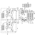
図1は、本実施の形態1に係る空気調和装置である。図1に示すように、この実施の形態の空気調和装置は、2台の熱源機A,Bを並列接続して備え、また、3台の室内機C,D,Eを並列接続して備え、更に、熱源機A,Bと室内機C,D,Eとの間に中継機Fを備えている。熱源機A,Bはそれぞれの定格容量が異なり、熱源機Aの方が熱源機Bよりも定格容量が大きな熱源機である。また、熱源機A,Bは各々圧縮機1,1と、四方弁2,2と、熱源機側熱交換器3,3と、アキュムレータ4,4と、各圧縮機1,1から吐出される冷媒の圧力を各々検出する冷媒圧力検出手段35,35と、各圧縮機1,1から吐出される冷媒の温度を各々検出する冷媒温度検出手段36,36を有し、室内機C,D,Eは各々第1の流量制御手段9c,9d,9eと、利用側熱交換器5c,5d,5eとを有する。中継機Fは第1の分岐部10と、第2の分岐部11と、気液分離器12と、第3の流量制御手段13と、第4の流量制御手段15と、第1の熱交換器16と、第2の熱交換器17とを有する。
Embodiment 1 FIG.
FIG. 1 shows an air conditioner according to the first embodiment. As shown in FIG. 1, the air conditioner of this embodiment includes two heat source units A and B connected in parallel, and three indoor units C, D, and E connected in parallel. Furthermore, a relay unit F is provided between the heat source units A and B and the indoor units C, D and E. The heat source machines A and B have different rated capacities, and the heat source machine A is a heat source machine having a larger rated capacity than the heat source machine B. The heat source machines A and B are discharged from the compressors 1 and 1, the four-
複数の熱源機A,Bと中継機Fとは、第1の接続配管6と第2の接続配管7という2本の冷媒配管を介して接続されている。第1の接続配管6は利用側熱交換器5c,5d,5eで熱交換された冷媒を中継機Fを介して、複数台の熱源機A,Bに送る直径の大きな吸入管31であり、第2の接続配管7は圧縮機1,1から吐出した冷媒を中継機Fを介して室内機C,D,Eに送る、第1の接続配管6より直径の小さい吐出管30である。
The plurality of heat source units A and B and the relay unit F are connected via two refrigerant pipes, a
また、6c,6d,6eはそれぞれ室内機C,D,E内の利用側熱交換器5c,5d,5eの一端と中継機F内の第1の分岐部10とを接続する第3の接続配管であり、また、7c,7d,7eはそれぞれ室内機C,D,E内の利用側熱交換器5c,5d,5eの他端と中継機F内の第2の分岐部11とを第1の流量制御手段9c,9d,9eを介して接続する第4の接続配管である。更に、8a,8b,8c,8d,8e,8fは第1の分岐部10に設けられた切換弁であり、切換弁8b,8d,8fは気液分離器12において分離されたガス冷媒が流出する配管と第3の接続配管6c,6d,6eとを接続する配管に設けられ、切換弁8a,8c,8eは第3の接続配管6c,6d,6eと第1の接続配管6とを接続する配管に設けられている。
6c, 6d, and 6e are third connections for connecting one end of the use
第2の分岐部11は、気液分離機器12からの液冷媒を第3の流量制御手段13を介して流出する配管と、第4の接続配管7c,7d,7eとを接続する。また、第3の流量制御手段13と第2の分岐部11との間で第1のバイパス配管14が分岐し、第1のバイパス配管14は第4の流量制御手段15を介して第1の接続配管6に接続されている。第1の熱交換器16は、第3の流量制御手段13と第1のバイパス配管14が分岐する部分との間に設けられ、第3の流量制御手段13から流出した液冷媒と第1のバイパス配管14を流れる冷媒との間で熱交換を行う。第2の熱交換器17は気液分離機12と第3の流量制御手段13との間に設けられ、気液分離器12から流出した冷媒と第1のバイパス配管14を流れる冷媒との間で熱交換を行う。
The
18乃至21は熱源機A,B内の配管に設けられた逆止弁であり、逆止弁18は第2の接続配管7に設けられ、熱源機側熱交換器3から気液分離器12へのみ冷媒の流通を可能とする。逆止弁19は第1の接続配管6に設けられ、中継機Fから四方弁2へのみ冷媒の流通を可能とする。
逆止弁20は第1の接続配管6と第2の接続配管7とを接続する第2のバイパス配管32に設けられた逆止弁であり、第1の接続配管6から第2の接続配管7へのみ冷媒の流通を可能とする。逆止弁21は、第1の接続配管6と第2の接続配管7とを接続する第3のバイパス配管33に設けられ、第1の接続配管6から第2の接続配管7へのみ冷媒の流通を可能とする。尚、第2のバイパス配管32は四方弁2と逆止弁19の間で第1の接続配管6から分岐し、逆止弁18の冷房主体運転時下流側で第2の接続配管7に合流する配管である。第3のバイパス配管33は逆止弁19の冷房主体運転時上流側で第1の接続配管6から分岐し、逆止弁18と熱源機側熱交換器3との間で第2の接続配管7に合流する配管である。
The
22は、熱源機A,B内に収容され、複数の熱源機A,Bに向かう吸入管31である第1の接続配管6に設けられた第2の流量制御手段である。この第2の流量制御手段22は、中継機Fから各熱源機A,Bへ分岐した位置であって、逆止弁19,19の手前の第1の接続配管6,6に設けられ、第4の流量制御手段15の制御範囲を超えないように、例えば、電気式切換弁を使用するか、または電気式膨張弁を複数個並列に接続して使用する等の工夫をすることで、圧力損失を最小限に抑える。
22 is the 2nd flow control means provided in the
更に、空気調和装置は制御装置44を有し、制御装置44は、熱源機運転容量制御手段34、流量制御手段37、冷媒不足検知手段38、始動手段39、停止手段40、管理手段41の各機能を有する。
Further, the air conditioner has a
熱源機運転容量制御手段34の機能は、熱源機A,Bが同時に運転される場合に、定格容量の小さい熱源機Bの運転容量を、定格容量の大きい熱源機Aの運転容量よりも小さくするよう制御を行う。流量制御手段37の機能は、冷媒圧力検出手段35及び冷媒温度検出手段36において検出された圧縮機1,1の吐出側の冷媒圧力及び冷媒温度に基づいて第2の流量制御手段22,22の開度を制御するものである。 The function of the heat source machine operating capacity control means 34 is to make the operating capacity of the heat source machine B with a small rated capacity smaller than the operating capacity of the heat source machine A with a large rated capacity when the heat source machines A and B are operated simultaneously. Do the control. The function of the flow rate control means 37 is based on the refrigerant pressure and refrigerant temperature on the discharge side of the compressors 1, 1 detected by the refrigerant pressure detection means 35 and the refrigerant temperature detection means 36. It controls the opening.
冷媒不足検知手段38の機能は、熱源機A,Bの何れもが運転中である場合、又は、熱源機A,Bのうち一方の熱源機(例えばA)が運転中であり、他方の熱源機(例えばB)が停止中である場合に、運転中の熱源機(例えばA)に冷媒不足が発生したことを検知するものである。始動手段39の機能は、冷媒不足検知手段38により検知した情報に基づいて、停止中の熱源機(例えばB)を始動させるものである。停止手段40の機能は、冷媒不足検知手段38により検知した情報に基づいて、運転中であった熱源機(例えばA)を停止させるものである。更に、管理手段41の機能は 始動手段39と停止手段40を働かせて、複数の熱源機A,Bの運転と停止を順次切り換えて管理するものである。
The function of the refrigerant shortage detection means 38 is that both the heat source devices A and B are in operation, or one of the heat source devices A and B is operating (for example, A) and the other heat source is in operation. When the machine (for example, B) is stopped, it detects that a refrigerant shortage has occurred in the operating heat source machine (for example, A). The function of the starting means 39 is to start a stopped heat source machine (for example, B) based on the information detected by the refrigerant
次に、上記構成の空気調和装置の各空調運転について説明する。まず、冷暖房同時運転における冷房主体の場合について、室内機C,Dが冷房運転であり、室内機Eのみが暖房運転であるとする。この場合には、切換弁8a,8c,8fは開口され、8b,8d,8eは閉止されている。冷媒の流れは、図2に実線矢印で示すように、熱源機A,Bのそれぞれの圧縮機1,1で圧縮された高温高圧のガス冷媒が四方弁2,2を経て、熱源機側熱交換器3,3へと流入し、ここで空気・水などと熱交換して気液2相で高温高圧の冷媒となる。
Next, each air conditioning operation of the air conditioner having the above-described configuration will be described. First, it is assumed that the indoor units C and D are in the cooling operation and only the indoor unit E is in the heating operation in the case of cooling mainly in the simultaneous cooling and heating operation. In this case, the switching
熱源機側熱交換器3,3を出た冷媒は、逆止弁18,18を経て、熱源機A,Bの冷媒の合流点に達し、第2の接続配管7を通り、中継機Fの気液分離器12へ流入する。この気液分離器12内において冷媒はガス冷媒と液冷媒に分離され、ガス冷媒は第1の分岐部10に流入し、開口している切換弁8fを経て第3の接続配管6eを通り、暖房運転中の室内機Eに流入する。室内機E内の利用側熱交換器5eで室内空気と熱交換して室内を暖房すると、ガス冷媒は凝縮し、液化する。
The refrigerant that has exited the heat source device side heat exchangers 3 and 3 passes through the
利用側熱交換器5eを出た冷媒は、利用側熱交換器5eの出口における過冷却度に基づいて自動制御がなされている第1の流量制御手段9eを通り、圧縮機1からの吐出圧力である高圧と、冷媒回路循環後の圧縮機1への吸入圧力である低圧との中間の圧力にあたる中間圧まで減圧されて、第2の分岐部11に流入する。一方、気液分離器12においてガス冷媒と分離された液冷媒は、第3の流量制御手段13において、第1の流量制御手段9eで調整された中間圧と同程度の圧力となるよう調整され、第2の分岐部11に流入する。また、このとき液冷媒の一部は第1のバイパス配管14へ流入し、第4の流量制御手段15で低圧まで減圧されて、第1の熱交換器16において第3の流量制御手段13から流出した冷媒と熱交換を行い、更に第2の熱交換器17において、気液分離器12から第3の流量制御手段13に流入する冷媒との間で熱交換を行い、第1の分岐部10に流入する。
The refrigerant that has exited the use
室内機Eから流出した中間圧の冷媒と、気液分離器12からの液冷媒とは、第2の分岐部11において合流し、第4の接続配管7c,7dへ分岐して流れ、冷房運転中の室内機C,Dに流入する。室内機C,D内では、第1の流量制御手段9c,9dを通って減圧され、低圧冷媒となる。尚、第1の流量制御手段9c,9dは、利用側熱交換器5c,5dの出口側冷媒の過熱度により開度が調整されている。
The intermediate-pressure refrigerant that has flowed out of the indoor unit E and the liquid refrigerant from the gas-
続いて、利用側熱交換器5c,5dで室内空気と熱交換して室内を冷却した冷媒は蒸発し、ガス化する。利用側熱交換器5c,5dを出た冷媒は第3の接続配管6c,6dを通り、中継機F内の第1の分岐部10に流入して、開口している切換弁8a,8cを通り、第1のバイパス配管14からの冷媒と合流して、第1の接続配管6へ流入する。
Subsequently, the refrigerant having cooled the room by exchanging heat with room air in the use
第1接続配管6を流れる冷媒は、各熱源機A,Bに分配されるが、その際、冷媒不足検知手段38において各熱源機A,Bに冷媒の不足があるか否かを検知し、流量制御手段37において第2の流量制御手段22の開度を制御し、各熱源機A,Bに分配される冷媒量を調整する。
The refrigerant flowing through the
冷媒不足検知手段38においては、以下のようにして各熱源機A,Bを流れる冷媒が不足したことを判断する。即ち、各冷媒圧力検出手段35において、それぞれの圧縮機1,1から吐出される冷媒の圧力を検出し、検出された圧力が極端に低い場合には熱源機は冷媒不足と判断する。また、各冷媒温度検出手段36においてそれぞれの圧縮機1,1から吐出される冷媒の温度を検出し、検出された温度が極端に高い場合には、冷媒不足と判断する。更に、圧縮機1の吸入側の冷媒圧力及び冷媒温度を検出し、吸入側の冷媒圧力における飽和温度と圧縮機吸入側の冷媒温度との差(スーパーヒート)が大きい場合にも冷媒不足と判断する。また、中継機Fに流入する冷媒圧力及び冷媒温度を検出し、これらの値により求めた過冷却度が冷房又は冷房主体運転の際に極端に低ければ冷媒不足と判断する。 In the refrigerant shortage detection means 38, it is determined that the refrigerant flowing through the heat source units A and B is insufficient as follows. That is, the refrigerant pressure detection means 35 detects the pressure of the refrigerant discharged from the compressors 1 and 1, and if the detected pressure is extremely low, the heat source unit determines that the refrigerant is insufficient. Further, the refrigerant temperature detection means 36 detects the temperature of the refrigerant discharged from the compressors 1 and 1, and when the detected temperature is extremely high, it is determined that the refrigerant is insufficient. Further, the refrigerant pressure and the refrigerant temperature on the suction side of the compressor 1 are detected, and it is determined that the refrigerant is insufficient even if the difference (superheat) between the saturation temperature and the refrigerant temperature on the suction side of the compressor is large. To do. Further, the refrigerant pressure and the refrigerant temperature flowing into the relay unit F are detected, and if the degree of supercooling obtained from these values is extremely low during cooling or cooling main operation, it is determined that the refrigerant is insufficient.
冷媒不足検知手段38において、一方の熱源機(例えばA)の冷媒不足が生じたと判断した場合には、かかる冷媒量の不足している熱源機(例えばA)の第2の流量制御手段22の開度を大きくし、逆に、冷媒量の多すぎる熱源機(例えばB)の第2の流量制御手段22の開度を小さくするよう流量制御手段37において制御を行う。これにより、冷媒の偏流が生じた場合にも、元の正常な冷媒量に回復させることができる。
When the refrigerant
各熱源機A,Bに分配された冷媒は、逆止弁19、四方弁2、アキュムレータ4を経て圧縮機1に吸入される。ここで、第1の接続配管6は低圧、第2の接続配管7は高圧であるため、第2のバイパス配管32を通って、低圧側の吸入管31から高圧側の吐出管30へと冷媒が流れることはない。
The refrigerant distributed to the heat source devices A and B is sucked into the compressor 1 through the
次に、冷暖同時運転における暖房主体運転について説明する。ここでは、室内機C,Dが暖房、室内機Eのみが冷房の場合について説明する。この場合には、切換弁8b,8d,8eは開口し、切換弁8a,8c,8fは閉止されている。冷媒の流れを以下に説明する。
Next, the heating main operation in the simultaneous cooling and heating operation will be described. Here, the case where the indoor units C and D are heating and only the indoor unit E is cooling will be described. In this case, the switching
図3に実線矢印で示すように、熱源機A,Bのそれぞれの圧縮機1,1で圧縮された高温高圧のガス冷媒は四方弁2,2経て、第2のバイパス配管32,32に入り、逆止弁20,20を通り、熱源機A,Bの冷媒が合流して第2の接続配管7へ流入する。続いて、中継機Fの気液分離器12内で冷媒の気液が分離され、ガス冷媒は第1の分岐部10へ、液冷媒は第3の流量制御手段13の設けられている配管へ流入する。第1の分岐部10でガス冷媒は、開口している切換弁8b,8dを通り、第3の接続配管6c,6dを経て、暖房運転中の室内機C,Dに流入し、利用側熱交換器5c,5dで室内空気と熱交換して室内を暖房し、ガス冷媒は凝縮液化する。更に、この冷媒は利用側熱交換器5c,5dの出口の過冷却度により制御されている第1の流量制御手段9c,9dにおいて中間圧まで減圧され、第4の接続配管7c,7dから第2の分岐部11に流入する。
As indicated by solid arrows in FIG. 3, the high-temperature and high-pressure gas refrigerant compressed by the compressors 1 and 1 of the heat source devices A and B enters the
第4の接続配管7c,7dからの冷媒は、第2の分岐部11において、気液分離器12から送られた液冷媒と合流し、第4の接続配管7eを通り、冷房運転中の室内機Eへ流入する。室内機Eでは液冷媒が第1の流量制御手段9eにより低圧まで減圧され、利用側熱交換器5eで室内空気と熱交換して室内を冷房し、液冷媒は蒸発、ガス化する。続いて、第3の接続配管6eを通り、第1の分岐部10に流入し、開口している切換弁8eを経て、第1のバイパス配管14からの冷媒と合流し、第1の接続配管6に流入する。ここで、第1のバイパス配管14からの冷媒は第3の流量制御手段13から流出した冷媒の一部が分岐したものであり、第4の流量制御手段15により低圧まで減圧されたものである。
The refrigerant from the
第1接続配管6を流れる冷媒は、各熱源機A,Bに分配されるが、その際、上記冷房主体運転の場合と同様に、冷媒不足検知手段38において各熱源機A,Bに冷媒の不足があるか否かを検知し、流量制御手段37において第2の流量制御手段22の開度を制御し、各熱源機A,Bに分配される冷媒量を調整する。
The refrigerant flowing through the
そして、第1の接続配管6は、第3のバイパス配管33,33に流入し、逆止弁21,21を経て、熱源機側熱交換器3,3に入り更に蒸発し、ガス状態となり、四方弁2,2、アキュムレータ4,4を経て圧縮機1,1に吸入される。ここで、上記冷房主体運転と同様に、第1の接続配管6は低圧、第2の接続配管7は高圧のため、逆止弁18,19を冷媒が流れることはない。
Then, the
以上より、室内機C,D,Eからの冷媒を複数台の熱源機A,Bに送る吸入管31に第2の流量制御手段22,22を設け、それらの開度を各圧縮機1,1の吐出圧力と吐出温度に基づいて制御することで、複数の熱源機A,Bに各々流入する冷媒量を偏りなく均等に割り振ることができる。よって、従来のように、例えば熱源機Aのみに多量の冷媒が偏流してアキュムレータ4内の油濃度を低下させ圧縮機1に流入する油の濃度を不足させたり、液体の冷媒を圧縮機1に流入させたりして圧縮機1を故障させるといったことがなく、安定した運転を確保することが可能である。また、アキュムレータ4内の油濃度を低下させないためにその大きさを大きくするといった必要がなくなり、小さなアキュムレータ4を使用できるのでコストを低減することができる。更に、立体的な構造の分配器を使用していないので新たなコスト負担も生じない。
As described above, the second flow rate control means 22 and 22 are provided in the
上記のような定格容量の異なる熱源機A,Bを同時に運転する場合には、熱源機運転容量制御手段34において、定格容量の小さい熱源機Bの運転容量を、定格容量の大きい熱源機Aの運転容量よりも小さくするよう制御する。これにより、意図的に冷媒を熱源機Bよりも熱源機Aへ多く偏流させることができ、定格容量の大きい熱源機Aよりも定格容量の小さい熱源機Bの方のアキュムレータ4の大きさを小さくしても、圧縮機1の故障を生じる恐れがなく、よりコストを低減することができる。
When simultaneously operating the heat source units A and B having different rated capacities as described above, the heat source unit operating capacity control means 34 uses the operating capacity of the heat source unit B having a smaller rated capacity as the operating capacity of the heat source unit A having a larger rated capacity. Control to make it smaller than the operating capacity. As a result, the refrigerant can be deliberately drifted to the heat source unit A more than the heat source unit B, and the size of the
また、熱源機A,Bのうち一方の熱源機(例えばA)が運転中であり、他方の熱源機(例えばB)が停止中である場合に、冷媒不足検知手段38が一方の熱源機(例えばA)に冷媒不足が生じたと判断した場合には、冷媒不足検知手段38により検知した情報に基づき、停止中の熱源機(例えばB)を始動手段39において始動させる。これにより、運転の停止している熱源機B内に冷媒を滞留させないようにすることができる。
In addition, when one of the heat source devices A and B is operating (for example, A) and the other heat source device (for example, B) is stopped, the refrigerant
始動手段39により停止中の熱源機(例えばB)を始動させた後、大きな運転容量が必要でない場合は、運転中であった熱源機(例えばA)を停止手段40において停止させ、熱源機A,Bの運転と停止を切り換える。その後、このような熱源機A,Bの運転と停止の切り換えを順次繰り返し行うよう管理手段41において管理する。これにより、運転停止中の熱源機A又はBの内部に冷媒を滞留させないようにすることができる。尚、熱源機A,Bの切り換えは冷媒不足検知手段38により、冷媒の不足を検知した場合のみならず、予め設定した所定時間を超えた際に、各熱源機A,Bの運転、停止を切り換えることとしてもよい。
If a large operating capacity is not required after starting the stopped heat source unit (for example, B) by the
さらに、一方の熱源機(例えばA)のみ冷房または冷房主体運転している場合、運転停止中の熱源機(例えばB)の逆止弁18に冷媒回路内の異物が付着する等の不具合が生じると、逆止弁18の弁閉止機構が不十分となり、冷媒が逆流する恐れがある。このような場合にも運転中の熱源機(例えばA)は冷媒不足となるので、冷媒不足検知手段38において冷媒不足を検知し、始動手段39において運転停止中の熱源機(例えばB)を強制的に始動させて、運転停止中の熱源機(例えばB)内に冷媒を滞留させないようにする。
Furthermore, when only one of the heat source units (for example, A) is performing cooling or cooling-main operation, there is a problem that foreign matter in the refrigerant circuit adheres to the
また、一方の熱源機(例えばA)のみ暖房または暖房主体運転している場合、運転停止中の熱源機(例えばB)の第2の流量制御手段22に冷媒回路内の異物が付着する等が起こると、第2の流量制御手段22の弁閉止機構が不十分となり、冷媒が流入する恐れがある。この場合にも同様に、運転中の熱源機(例えばA)の運転状況より冷媒検知手段38において冷媒量の過不足を検知し、運転停止中の熱源機(例えばB)を強制的に運転させ、冷媒を滞留させないようにする。 In addition, when only one heat source unit (for example, A) is heating or heating-mainly operated, foreign matters in the refrigerant circuit may adhere to the second flow rate control means 22 of the heat source unit (for example, B) that has been stopped. If this occurs, the valve closing mechanism of the second flow rate control means 22 becomes insufficient, and the refrigerant may flow in. Similarly, in this case, the refrigerant detection means 38 detects an excess or deficiency of the refrigerant amount from the operating state of the operating heat source unit (for example, A), and forcibly operates the stopped heat source unit (for example, B). Do not allow refrigerant to stay.
本実施形態では、定格容量の異なる熱源機2台に室内機3台、中継機1台を接続した場合について説明したが、熱源機は定格容量が同じであってもよく、2台以上としてもよい。この場合に一方の熱源機のみ運転中であり、他方の熱源機が停止している場合は、一部の熱源機のみ運転中であり、残りの熱源機が停止していることとなる。また、1台、2台、又は4台以上の室内機を接続してもよい。また、冷房主体運転、暖房主体運転について説明したが、全ての室内機C,D,Eが冷房運転のみ又は暖房運転のみを行ってもよい。また、冷暖同時運転の可能な空気調和装置でなくてもよく、冷房運転と暖房運転を切り換え可能であってもよく、冷房運転のみ、或いは、暖房運転のみの空気調和装置であってもよい。また、熱源機側熱交換器3と直列または並列に氷蓄熱槽や水蓄熱槽(湯を含む)が設置されてもよい。 In this embodiment, the case where three indoor units and one relay unit are connected to two heat source units having different rated capacities has been described. However, the heat source units may have the same rated capacity, or two or more units. Good. In this case, when only one heat source machine is operating and the other heat source machine is stopped, only a part of the heat source machines are operating and the remaining heat source machines are stopped. One, two, or four or more indoor units may be connected. Moreover, although the cooling main operation and the heating main operation have been described, all the indoor units C, D, and E may perform only the cooling operation or only the heating operation. Further, the air conditioner may not be capable of simultaneous cooling and heating operation, and may be switched between cooling operation and heating operation, or may be an air conditioner only for cooling operation or only for heating operation. Further, an ice heat storage tank or a water heat storage tank (including hot water) may be installed in series or in parallel with the heat source device side heat exchanger 3.
実施の形態2.
上記実施形態1においては熱源機A,Bと室内機C,D,Eを接続する配管が第1の接続配管6と第2の接続配管7の2本であったが、このような接続配管が3本である空気調和装置について以下に説明する。
In the first embodiment, there are two pipes for connecting the heat source devices A and B and the indoor units C, D, and E, the
図4に示すように、本実施形態に係る空気調和装置は、実施形態1と同様2台の熱源機A,Bを並列接続して備え、また、3台の室内機C,D,Eを並列接続して備えているが、上記実施形態1とは異なり、各室内機C,D,Eにはそれぞれ中継機F,G,Hが設けられている。熱源機A,Bは各々圧縮機1,1と、熱源機側熱交換器3,3とを有し、更に、本実施形態では四方弁を備えておらず、第1の切換弁23と第2の切換弁24により冷媒の流れを切り換えている。また、第3の分岐部28を新たに有しており、アキュムレータは図示を省略したが必要により設けてもよい。
As shown in FIG. 4, the air conditioning apparatus according to the present embodiment includes two heat source units A and B connected in parallel as in the first embodiment, and includes three indoor units C, D, and E. Unlike the first embodiment, each indoor unit C, D, and E is provided with a relay device F, G, and H, respectively. The heat source machines A and B have compressors 1 and 1 and heat source machine side heat exchangers 3 and 3, respectively. Further, in this embodiment, the four-way valve is not provided, and the
室内機C,D,Eは各々第1の流量制御手段9c,9d,9eと、利用側熱交換器5c,5d,5eとを有し、中継機F,G,Hは第3の切換弁25c,25d,25eと、第4の切換弁26c,26d,26eとを有する。
Each of the indoor units C, D, E has first flow rate control means 9c, 9d, 9e and utilization
複数の熱源機A,Bと中継機F,G,Hとは、第1の接続配管6と、第2の接続配管7と、第5の接続配管27という3本の冷媒配管を介して接続されている。第1の接続配管6は一端が第2の切換弁24と接続され、他端が分岐してそれぞれ第3の切換弁25c,25d,25eと接続されている。第2の接続配管7は一端が熱源機側熱交換器3と接続され、他端が第4の接続配管7c,7d,7eと接続されている。ここで、第2の接続配管7は冷房主体運転の際は、熱源機A,Bから出て室内機C,D,Eへ向かう吐出管30となり、暖房主体運転の際には熱源機A,Bに向かう吸入管31となる。第2の接続配管7には、各熱源機A,Bの内部であり、利用側熱交換器3と各熱源機A,Bから延びる第2の接続配管7が合流する位置との間に第2の流量制御手段22が各々設けられている。第5の接続配管27は一端が熱源機A,B内で分岐して第1の切換弁23及び圧縮機1と接続され、他端が第4の切換弁26c,26d,26eと各々接続されている。
The plurality of heat source devices A and B and the relay devices F, G, and H are connected through three refrigerant pipes, ie, a
第3の接続配管6c,6d,6eは各々利用側熱交換器5c,5d,5eと中継機F,G,Hとを接続し、第4の接続配管7c,7d,7eはそれぞれ第1の流量制御手段9c,9d,9eと第2の接続配管7とを接続する。
The
このように構成された空気調和装置の各空調運転について説明する。まず、冷暖房同時運転における冷房主体の場合について説明する。ここでは、室内機C,Dが冷房運転、室内機Eのみが暖房運転の場合について説明する。この場合、第1の切換弁23、第3の切換弁25c,25d,第4の切換弁26eは開口しており第2の切換弁24、第4の切換弁26c,26d、第3の切換弁25eは閉止している。
Each air conditioning operation of the air conditioner configured as described above will be described. First, a description will be given of the case of mainly cooling in the simultaneous cooling and heating operation. Here, the case where the indoor units C and D are in the cooling operation and only the indoor unit E is in the heating operation will be described. In this case, the
図5に、冷媒の流れを実線矢印で示す。圧縮機1,1で圧縮された高温高圧のガス冷媒は第3の分岐部28,28で分流し、一部の冷媒は、第1の切換弁23,23を経て、熱源機側熱交換器3,3へと流入し、ここで空気、水などと熱交換して高温高圧の液冷媒となり、複数の熱源機A,Bから出て室内機C,D,Eへ向かう吐出管30に設けられている第2の流量制御手段22,22を経て、熱源機A,Bの冷媒が合流する。ここで、第2の流量制御手段22は、上記実施形態1と同様に、冷媒圧力検出手段35及び冷媒温度検出手段36において各々検出された冷媒圧力及び冷媒温度に基づいて流量制御手段37により制御され、冷媒量の調整を行っている。
In FIG. 5, the flow of the refrigerant is indicated by solid arrows. The high-temperature and high-pressure gas refrigerant compressed by the compressors 1 and 1 is diverted by the
第2の接続配管7の冷媒は第4の接続配管7c,7dを通り、冷房運転中の室内機C,Dに流入する。そして、利用側熱交換器5c,5dの出口の過冷却度度により制御されている第1の流量制御手段9c,9dにより低圧まで減圧され、次いで利用側熱交換器5c,5dで空気などと熱交換して室内を冷却し、液冷媒は蒸発、ガス化する。この冷媒は第3の接続配管6c,6dを経て中継機F,Gへ流入する。そして、開口している第3の切換弁25c,25dを通り、第1の接続配管6へ流入する。その後、各熱源機A,Bに分配され、各々圧縮機1,1に吸入される。
The refrigerant in the
各々の圧縮機1,1から吐出され高温高圧のガス冷媒のうち、第3の分岐部28,28において第5の接続配管27に流入した冷媒は合流して中継機Hへ流入する。そして、開口している第4の切換弁26eを通り、第3の接続配管6eを経て、暖房運転中の室内機Eに流入し、利用側熱交換器5eで空気などと熱交換して室内を暖房し、ガス冷媒は凝縮、液化する。更に、利用側熱交換器5eから流出し、第1の流量制御手段9eを通って減圧され、第4の接続配管7eに流入する。
Of the high-temperature and high-pressure gas refrigerant discharged from the compressors 1 and 1, the refrigerant that has flowed into the
次に、暖房主体運転の場合について説明する。ここでは、室内機C,Dが暖房運転、室内機Eのみが冷房運転の場合について説明する。第2の切換弁24、第3の切換弁25e及び第4の切換弁26c,26dは開口しており、第1の切換弁23、第3の切換弁25c,25d及び第4の切換弁26eは閉止している。
Next, the case of heating main operation will be described. Here, the case where the indoor units C and D are in the heating operation and only the indoor unit E is in the cooling operation will be described. The
図6に、冷媒の流れを実線矢印で示す。圧縮機1,1で圧縮された高温高圧のガス冷媒は第5の接続配管27を経て、中継機F,Gへ流入する。開口している第4の切換弁26c,26dを通り、第3の接続配管6c,6dを経て、暖房しようとしている室内機C,Dに流入し、利用側熱交換器5c,5dで空気などと熱交換して室内を暖房し、ガス冷媒は凝縮、液化する。更に、利用側熱交換器5c,5dの出口の過冷却度により制御されている第1の流量制御手段9c,9dを通って減圧され、第4の接続配管7c,7dへと流入する。
In FIG. 6, the flow of the refrigerant is indicated by solid arrows. The high-temperature and high-pressure gas refrigerant compressed by the compressors 1 and 1 flows into the relays F and G through the
第4の接続配管7c,7dからの冷媒は2方向に分流し、一方は熱源機A,Bに向かう吸入管31となる第2の接続配管7を通り、第2の流量制御手段22を通る。ここで、第2の流量制御手段22は、上記と同様に、流量制御手段37において、冷媒圧力検出手段35及び冷媒温度検出手段36において各々検出された冷媒圧力及び冷媒温度に基づいて制御され、冷媒量の調整を行っている。さらに、冷媒は熱源機側熱交換器3,3へと流入し、熱源側熱交換器3,3内で空気、水などと熱交換して液冷媒は蒸発、ガス化し、開口している第2の切換弁24を通り、圧縮機1,1へと吸入される。
The refrigerant from the
また、第4の接続配管7c,7dから2方向に分流した冷媒のうち他方の冷媒は、第4の接続配管7eを通り、冷房運転中の室内機Eに流入する。そして、利用側熱交換器5eの出口の過冷却度により開度が制御されている第1の流量制御手段9eにより低圧まで減圧され、次いで、利用側熱交換器5eで空気などと熱交換して室内を冷却し、液冷媒は蒸発、ガス化する。その後、利用側熱交換器5eからの冷媒は第3の接続配管6eを経て、開口している第3の切換弁25eを通り、第1の接続配管6へ流入し、熱源機A,Bに入り、各々の熱源機側熱交換器3,3でガス化した冷媒と第1の合流部29,29で合流し、圧縮機1,1に吸入される。本実施形態2においても、上記実施形態1と同様の効果を得ることができる。
Moreover, the other refrigerant | coolant of the refrigerant | coolant which branched into 2 directions from the 4th connection piping 7c and 7d flows into the indoor unit E in air_conditionaing | cooling operation through the 4th connection piping 7e. Then, the pressure is reduced to a low pressure by the first flow rate control means 9e whose opening degree is controlled by the degree of supercooling at the outlet of the use
実施の形態3.
上記実施形態1、2では、複数の熱源機A,Bに向かう吸入管31、又は、複数の熱源機A,Bから出て室内機C,D,Eへ向かう吐出管30に各々第2の流量制御手段22を設けたが、本実施形態ではこれらに換えて、図7に示すように、各々の吐出管30を相互に接続する第4のバイパス管42及び開閉弁43を備えている。
Embodiment 3 FIG.
In the first and second embodiments, the
この第4のバイパス管42及び開閉弁43により、運転中の熱源機(例えばB)の圧縮機1から吐出した高圧の冷媒一部を運転の停止している熱源機(例えばA)に送ることができる。これにより、万一逆止弁19に冷媒回路内の異物等の付着により、冷媒が逆流した場合でも上記実施形態1,2と同様に一部の熱源機(例えばA)に冷媒を滞留させないようにすることができる。
By the fourth bypass pipe 42 and the on-off
A,B 熱源機、 C,D,E 室内機、1 圧縮機、 3 熱源機側熱交換器、5c,5d,5e 利用側熱交換器、9c,9d,9e 第1の流量制御手段、22 第2の流量制御手段 、30 吐出管、31 吸入管、34 熱源機運転容量制御手段、35 冷媒圧力検出手段、36 冷媒温度検出手段、37 流量制御手段、38 冷媒不足検知手段、39 始動手段、40 停止手段、41 管理手段、42 第4のバイパス管、43 開閉弁。
A, B heat source machine, C, D, E indoor unit, 1 compressor, 3 heat source machine side heat exchanger, 5c, 5d, 5e utilization side heat exchanger, 9c, 9d, 9e first flow rate control means, 22 Second flow rate control means 30
Claims (7)
Priority Applications (1)
| Application Number | Priority Date | Filing Date | Title |
|---|---|---|---|
| JP2006088395A JP4688711B2 (en) | 2006-03-28 | 2006-03-28 | Air conditioner |
Applications Claiming Priority (1)
| Application Number | Priority Date | Filing Date | Title |
|---|---|---|---|
| JP2006088395A JP4688711B2 (en) | 2006-03-28 | 2006-03-28 | Air conditioner |
Publications (2)
| Publication Number | Publication Date |
|---|---|
| JP2007263444A true JP2007263444A (en) | 2007-10-11 |
| JP4688711B2 JP4688711B2 (en) | 2011-05-25 |
Family
ID=38636603
Family Applications (1)
| Application Number | Title | Priority Date | Filing Date |
|---|---|---|---|
| JP2006088395A Active JP4688711B2 (en) | 2006-03-28 | 2006-03-28 | Air conditioner |
Country Status (1)
| Country | Link |
|---|---|
| JP (1) | JP4688711B2 (en) |
Cited By (20)
| Publication number | Priority date | Publication date | Assignee | Title |
|---|---|---|---|---|
| JP2009243761A (en) * | 2008-03-31 | 2009-10-22 | Mitsubishi Electric Corp | Refrigeration air conditioner |
| WO2010109832A1 (en) * | 2009-03-26 | 2010-09-30 | 三菱電機株式会社 | Refrigerator |
| WO2011074028A1 (en) * | 2009-12-15 | 2011-06-23 | 三菱電機株式会社 | Air conditioner |
| JP2011226704A (en) * | 2010-04-20 | 2011-11-10 | Mitsubishi Electric Corp | Refrigerating air conditioner, and refrigerating air conditioning system |
| JP2011257038A (en) * | 2010-06-08 | 2011-12-22 | Mitsubishi Electric Corp | Air conditioner |
| JP2012233630A (en) * | 2011-04-28 | 2012-11-29 | Mitsubishi Heavy Ind Ltd | Branch pipe and air conditioner |
| KR20140125242A (en) * | 2013-04-18 | 2014-10-28 | 엘지전자 주식회사 | An air conditioning system |
| KR20140125525A (en) * | 2013-04-19 | 2014-10-29 | 엘지전자 주식회사 | An air conditioning system |
| KR20140125524A (en) * | 2013-04-19 | 2014-10-29 | 엘지전자 주식회사 | An air conditioning system |
| WO2016129027A1 (en) * | 2015-02-09 | 2016-08-18 | 三菱電機株式会社 | Air conditioning device |
| JP2016211772A (en) * | 2015-05-07 | 2016-12-15 | ジョンソンコントロールズ ヒタチ エア コンディショニング テクノロジー(ホンコン)リミテッド | Air conditioner |
| WO2017068902A1 (en) * | 2015-10-22 | 2017-04-27 | 三菱重工業株式会社 | Air conditioning system |
| WO2018008139A1 (en) * | 2016-07-08 | 2018-01-11 | 三菱電機株式会社 | Refrigeration cycle apparatus and air-conditioning apparatus provided with same |
| JP2018054253A (en) * | 2016-09-30 | 2018-04-05 | ダイキン工業株式会社 | Refrigeration device |
| JP2018054172A (en) * | 2016-09-27 | 2018-04-05 | ダイキン工業株式会社 | Freezer |
| JP2018080883A (en) * | 2016-11-17 | 2018-05-24 | 日立ジョンソンコントロールズ空調株式会社 | Multi-room type air conditioner |
| CN108981215A (en) * | 2018-07-02 | 2018-12-11 | 合肥天鹅制冷科技有限公司 | A kind of air conditioner refrigerating surplus energy utility method |
| JP2020020576A (en) * | 2019-11-08 | 2020-02-06 | 三菱電機株式会社 | Refrigeration cycle device and air conditioner including the same |
| WO2020130756A1 (en) * | 2018-12-21 | 2020-06-25 | Samsung Electronics Co., Ltd. | Air conditioner |
| CN113544445A (en) * | 2019-03-27 | 2021-10-22 | Lg电子株式会社 | Air conditioning equipment |
Citations (5)
| Publication number | Priority date | Publication date | Assignee | Title |
|---|---|---|---|---|
| JPS5086765U (en) * | 1973-12-14 | 1975-07-23 | ||
| JPH11142010A (en) * | 1997-11-12 | 1999-05-28 | Mitsubishi Electric Corp | Refrigeration air conditioner |
| JP2000097481A (en) * | 1999-09-28 | 2000-04-04 | Sanyo Electric Co Ltd | Air conditioner |
| JP2000161804A (en) * | 1998-11-26 | 2000-06-16 | Mitsubishi Electric Corp | Refrigerating air conditioner |
| JP2000220894A (en) * | 1999-01-29 | 2000-08-08 | Sanyo Electric Co Ltd | Air conditioner and method for operating the same |
-
2006
- 2006-03-28 JP JP2006088395A patent/JP4688711B2/en active Active
Patent Citations (5)
| Publication number | Priority date | Publication date | Assignee | Title |
|---|---|---|---|---|
| JPS5086765U (en) * | 1973-12-14 | 1975-07-23 | ||
| JPH11142010A (en) * | 1997-11-12 | 1999-05-28 | Mitsubishi Electric Corp | Refrigeration air conditioner |
| JP2000161804A (en) * | 1998-11-26 | 2000-06-16 | Mitsubishi Electric Corp | Refrigerating air conditioner |
| JP2000220894A (en) * | 1999-01-29 | 2000-08-08 | Sanyo Electric Co Ltd | Air conditioner and method for operating the same |
| JP2000097481A (en) * | 1999-09-28 | 2000-04-04 | Sanyo Electric Co Ltd | Air conditioner |
Cited By (36)
| Publication number | Priority date | Publication date | Assignee | Title |
|---|---|---|---|---|
| JP2009243761A (en) * | 2008-03-31 | 2009-10-22 | Mitsubishi Electric Corp | Refrigeration air conditioner |
| CN102365507B (en) * | 2009-03-26 | 2015-04-01 | 三菱电机株式会社 | Refrigerator |
| WO2010109832A1 (en) * | 2009-03-26 | 2010-09-30 | 三菱電機株式会社 | Refrigerator |
| CN102365507A (en) * | 2009-03-26 | 2012-02-29 | 三菱电机株式会社 | Refrigerator |
| JP5496182B2 (en) * | 2009-03-26 | 2014-05-21 | 三菱電機株式会社 | refrigerator |
| WO2011074028A1 (en) * | 2009-12-15 | 2011-06-23 | 三菱電機株式会社 | Air conditioner |
| JPWO2011074028A1 (en) * | 2009-12-15 | 2013-04-25 | 三菱電機株式会社 | Air conditioner |
| JP5734205B2 (en) * | 2009-12-15 | 2015-06-17 | 三菱電機株式会社 | Air conditioner |
| JP2011226704A (en) * | 2010-04-20 | 2011-11-10 | Mitsubishi Electric Corp | Refrigerating air conditioner, and refrigerating air conditioning system |
| JP2011257038A (en) * | 2010-06-08 | 2011-12-22 | Mitsubishi Electric Corp | Air conditioner |
| JP2012233630A (en) * | 2011-04-28 | 2012-11-29 | Mitsubishi Heavy Ind Ltd | Branch pipe and air conditioner |
| KR102122587B1 (en) * | 2013-04-18 | 2020-06-15 | 엘지전자 주식회사 | An air conditioning system |
| KR20140125242A (en) * | 2013-04-18 | 2014-10-28 | 엘지전자 주식회사 | An air conditioning system |
| KR20140125524A (en) * | 2013-04-19 | 2014-10-29 | 엘지전자 주식회사 | An air conditioning system |
| KR20140125525A (en) * | 2013-04-19 | 2014-10-29 | 엘지전자 주식회사 | An air conditioning system |
| KR102136589B1 (en) | 2013-04-19 | 2020-07-22 | 엘지전자 주식회사 | An air conditioning system |
| KR102122568B1 (en) * | 2013-04-19 | 2020-06-15 | 엘지전자 주식회사 | An air conditioning system |
| GB2549897A (en) * | 2015-02-09 | 2017-11-01 | Mitsubishi Electric Corp | Air conditioning device |
| JPWO2016129027A1 (en) * | 2015-02-09 | 2017-10-12 | 三菱電機株式会社 | Air conditioner |
| WO2016129027A1 (en) * | 2015-02-09 | 2016-08-18 | 三菱電機株式会社 | Air conditioning device |
| GB2549897B (en) * | 2015-02-09 | 2020-07-22 | Mitsubishi Electric Corp | Air conditioning apparatus |
| JP2016211772A (en) * | 2015-05-07 | 2016-12-15 | ジョンソンコントロールズ ヒタチ エア コンディショニング テクノロジー(ホンコン)リミテッド | Air conditioner |
| WO2017068902A1 (en) * | 2015-10-22 | 2017-04-27 | 三菱重工業株式会社 | Air conditioning system |
| WO2018008139A1 (en) * | 2016-07-08 | 2018-01-11 | 三菱電機株式会社 | Refrigeration cycle apparatus and air-conditioning apparatus provided with same |
| EP3483523A4 (en) * | 2016-07-08 | 2019-12-11 | Mitsubishi Electric Corporation | Refrigeration cycle apparatus and air-conditioning apparatus provided with same |
| US10907866B2 (en) | 2016-07-08 | 2021-02-02 | Mitsubishi Electric Corporation | Refrigerant cycle apparatus and air conditioning apparatus including the same |
| EP3757483A1 (en) * | 2016-07-08 | 2020-12-30 | Mitsubishi Electric Corporation | Refrigeration cycle apparatus and air-conditioning apparatus provided with same |
| JP2018054172A (en) * | 2016-09-27 | 2018-04-05 | ダイキン工業株式会社 | Freezer |
| JP2018054253A (en) * | 2016-09-30 | 2018-04-05 | ダイキン工業株式会社 | Refrigeration device |
| JP2018080883A (en) * | 2016-11-17 | 2018-05-24 | 日立ジョンソンコントロールズ空調株式会社 | Multi-room type air conditioner |
| CN108981215A (en) * | 2018-07-02 | 2018-12-11 | 合肥天鹅制冷科技有限公司 | A kind of air conditioner refrigerating surplus energy utility method |
| WO2020130756A1 (en) * | 2018-12-21 | 2020-06-25 | Samsung Electronics Co., Ltd. | Air conditioner |
| US11473816B2 (en) | 2018-12-21 | 2022-10-18 | Samsung Electronics Co., Ltd. | Air conditioner |
| CN113544445A (en) * | 2019-03-27 | 2021-10-22 | Lg电子株式会社 | Air conditioning equipment |
| US11499727B2 (en) | 2019-03-27 | 2022-11-15 | Lg Electronics Inc. | Air conditioning apparatus |
| JP2020020576A (en) * | 2019-11-08 | 2020-02-06 | 三菱電機株式会社 | Refrigeration cycle device and air conditioner including the same |
Also Published As
| Publication number | Publication date |
|---|---|
| JP4688711B2 (en) | 2011-05-25 |
Similar Documents
| Publication | Publication Date | Title |
|---|---|---|
| JP4688711B2 (en) | Air conditioner | |
| JP4948016B2 (en) | Air conditioner | |
| JP4358559B2 (en) | Multi air conditioner | |
| JP2004219061A (en) | Multiple air conditioner equipped with a plurality of distributor capable of being blocked | |
| JP4553761B2 (en) | Air conditioner | |
| JP2004085195A (en) | Cooling heating simultaneous type multi air conditioner | |
| US7104087B2 (en) | Multi-type air conditioner | |
| JP2009243802A (en) | Heat pump type air conditioner | |
| JP4785508B2 (en) | Air conditioner | |
| US20210048216A1 (en) | Air-conditioning apparatus | |
| JP5186398B2 (en) | Air conditioner | |
| JP2006170541A (en) | Air conditioner | |
| KR20140139240A (en) | An air conditioning system | |
| JP2004324947A (en) | Air conditioning system | |
| JP5279768B2 (en) | Air conditioner | |
| KR20140125141A (en) | An air conditioning system | |
| JP5525906B2 (en) | Refrigeration cycle equipment | |
| KR101545816B1 (en) | An air conditioning system | |
| JP2601052B2 (en) | Air conditioner | |
| JP2003279174A (en) | Air conditioning device | |
| JPH0765825B2 (en) | Air conditioner | |
| JP2018128167A (en) | Air conditioner | |
| JP2013096640A (en) | Oil recovery method for multi-type air conditioning system, and multi-type air conditioning system | |
| EP4224093A1 (en) | Refrigeration device | |
| JP3791019B2 (en) | Air conditioner |
Legal Events
| Date | Code | Title | Description |
|---|---|---|---|
| A621 | Written request for application examination |
Free format text: JAPANESE INTERMEDIATE CODE: A621 Effective date: 20080821 |
|
| A977 | Report on retrieval |
Free format text: JAPANESE INTERMEDIATE CODE: A971007 Effective date: 20100518 |
|
| A131 | Notification of reasons for refusal |
Free format text: JAPANESE INTERMEDIATE CODE: A131 Effective date: 20100615 |
|
| RD01 | Notification of change of attorney |
Free format text: JAPANESE INTERMEDIATE CODE: A7421 Effective date: 20100727 |
|
| A521 | Request for written amendment filed |
Free format text: JAPANESE INTERMEDIATE CODE: A523 Effective date: 20100811 |
|
| TRDD | Decision of grant or rejection written | ||
| A01 | Written decision to grant a patent or to grant a registration (utility model) |
Free format text: JAPANESE INTERMEDIATE CODE: A01 Effective date: 20110208 |
|
| A01 | Written decision to grant a patent or to grant a registration (utility model) |
Free format text: JAPANESE INTERMEDIATE CODE: A01 |
|
| A61 | First payment of annual fees (during grant procedure) |
Free format text: JAPANESE INTERMEDIATE CODE: A61 Effective date: 20110215 |
|
| R150 | Certificate of patent or registration of utility model |
Ref document number: 4688711 Country of ref document: JP Free format text: JAPANESE INTERMEDIATE CODE: R150 Free format text: JAPANESE INTERMEDIATE CODE: R150 |
|
| FPAY | Renewal fee payment (event date is renewal date of database) |
Free format text: PAYMENT UNTIL: 20140225 Year of fee payment: 3 |
|
| R250 | Receipt of annual fees |
Free format text: JAPANESE INTERMEDIATE CODE: R250 |
|
| R250 | Receipt of annual fees |
Free format text: JAPANESE INTERMEDIATE CODE: R250 |
|
| R250 | Receipt of annual fees |
Free format text: JAPANESE INTERMEDIATE CODE: R250 |
|
| R250 | Receipt of annual fees |
Free format text: JAPANESE INTERMEDIATE CODE: R250 |
|
| R250 | Receipt of annual fees |
Free format text: JAPANESE INTERMEDIATE CODE: R250 |
|
| R250 | Receipt of annual fees |
Free format text: JAPANESE INTERMEDIATE CODE: R250 |
|
| R250 | Receipt of annual fees |
Free format text: JAPANESE INTERMEDIATE CODE: R250 |
|
| R250 | Receipt of annual fees |
Free format text: JAPANESE INTERMEDIATE CODE: R250 |
|
| R250 | Receipt of annual fees |
Free format text: JAPANESE INTERMEDIATE CODE: R250 |