JP2007253184A - Die for molding hollow extruded shape - Google Patents
Die for molding hollow extruded shape Download PDFInfo
- Publication number
- JP2007253184A JP2007253184A JP2006079867A JP2006079867A JP2007253184A JP 2007253184 A JP2007253184 A JP 2007253184A JP 2006079867 A JP2006079867 A JP 2006079867A JP 2006079867 A JP2006079867 A JP 2006079867A JP 2007253184 A JP2007253184 A JP 2007253184A
- Authority
- JP
- Japan
- Prior art keywords
- die
- port hole
- hollow
- holder
- mandrel
- Prior art date
- Legal status (The legal status is an assumption and is not a legal conclusion. Google has not performed a legal analysis and makes no representation as to the accuracy of the status listed.)
- Pending
Links
Images


Abstract
Description
この発明は、例えば、1又は複数の中空部を有するアルミニウム又はアルミニウム合金製の中空押出形材の成形用ダイスに関するものである。 The present invention relates to a die for forming a hollow extruded shape member made of aluminum or aluminum alloy having one or a plurality of hollow portions, for example.
一般に、アルミニウム又はアルミニウム合金製(以下に、単にアルミニウム製という)の中実の押出形材を成形するダイスは、押出形材を成形するベアリング部を有するダイと、このダイの押出形材側に配置されるダイバッカ、ダイ及びダイバッカを保持するダイリングとを具備し、更に押出形材側に、ボルスタ、また、ビレット径より大きな押出形材を成形する場合には、ダイのビレット側にスプレッダ・バッフルを配置している。 In general, a die for forming a solid extruded shape made of aluminum or an aluminum alloy (hereinafter simply referred to as aluminum) includes a die having a bearing portion for forming the extruded shape, and an extrusion shape side of the die. And a die ring for holding the die backer and a die ring for holding the die backer. Further, in the case of forming a bolster on the extruded shape side, or an extruded shape larger than the billet diameter, a spreader on the billet side of the die. A baffle is placed.
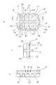
また、中空部を有するアルミニウム製の中空押出形材を成形する場合は、図8(b)に示すように、押出形材の外側を形成するベアリング部aを有するダイbに、ベアリング部aによって形成される空間内に挿入され、押出形材の中空部を形成するマンドレルcを保持するポートホールダイdを組み合わせたダイスが使用されている(例えば、特許文献1参照)。この中空押出形材成形用ダイスにおいて、ポートホールダイdは、マンドレルcと、マンドレルcを支え、またビレットを一時的に分断するブリッジeとビレットが通過するポートホールfとを具備し、また、ダイbとポートホールダイdはダイリングgによって保持されている。なお、マンドレルcは、その数と関係なく、3ないし4のブリッジeによって支えられている。また、このように形成されるダイスは、強度的に優れた熱間工具鋼が使用されている。なお、ダイbの押出形材の押出側には、バックダイhとボルスタiが配置されている。 Further, when forming an aluminum hollow extruded shape having a hollow portion, as shown in FIG. 8 (b), a die b having a bearing portion a that forms the outside of the extruded shape is formed by a bearing portion a. A die that is combined with a port hole die d that holds a mandrel c that is inserted into a formed space and forms a hollow portion of an extruded profile is used (for example, see Patent Document 1). In this hollow extrusion molding die, the port hole die d includes a mandrel c, a bridge e that supports the mandrel c and temporarily divides the billet, and a port hole f through which the billet passes. The die b and the port hole die d are held by a die ring g. The mandrel c is supported by three to four bridges e regardless of the number of the mandrels c. Moreover, the hot tool steel excellent in strength is used for the die formed in this way. Note that a back die h and a bolster i are disposed on the extrusion side of the extruded shape of the die b.
ところで、上記中空押出形材成形用ダイスを用いて成形された押出形材は、押出しの進行に応じて肉厚が変動する。また、同じビレットから押出された押出形材であっても、押出開始直後に押出加工された部分と、押出終了近くで押出加工された部分では、肉厚が変動する。これは、特にこの種のダイスにおいて、入熱(アルミニウムとダイス界面での接触伝達,加工発生熱,摩擦発生熱等)に対して、出熱(ダイス表面からの輻射・対流熱伝達による放熱)の方が大きく、押出進行と共にダイスの温度が低下し、ベアリング部の熱変形量が異なることが原因である。この傾向は大型のダイスほど顕著である。 By the way, the thickness of the extruded shape formed by using the hollow extrusion shape forming die varies with the progress of extrusion. Further, even in the case of an extruded shape extruded from the same billet, the wall thickness varies between a portion extruded immediately after the start of extrusion and a portion extruded near the end of extrusion. This is especially true for this type of die, with respect to heat input (contact transfer at the aluminum / die interface, heat generated by machining, heat generated by friction, etc.) and heat output (radiation from the surface of the die / heat dissipation by convective heat transfer). This is because the temperature of the die decreases with the progress of extrusion, and the amount of thermal deformation of the bearing portion differs. This tendency is more conspicuous for larger dies.
そこで、出願人等は、ダイスを、ベアリング部を有するダイと、ダイを保持するダイホルダーとの2部材にて形成し、ダイとダイホルダーの間に断熱空間を設け、ダイからの熱を小さくし、ベアリング部の温度を安定化させ、押出開始時と押出終了時の肉厚を小さくするダイスを提案した(特に、特許文献2参照)。
しかしながら、上記中空押出形材成形用ダイスに、特許第3243872号公報に記載の技術を適用しようとした場合、ダイに比べ、ポートホールダイが極端に大きくなり、押出中のポートホールダイの変形にダイが追随できず、耐えられる固定方法がないため、ダイのベアリング部とマンドレルのベアリング部の位置関係を制御するのが難しくなる。また、ダイをポートホールダイに固定できるように、ポートホールダイの大きさに合わせてダイを大きくすると、ダイの熱変動が大きくなり、中空押出形材の肉厚変動が大きくなる虞があり、特に、スプレッダーバッフルを用いて中空大型押出形材を成形する大型のダイスには適用が困難であるという問題があった。更に、近年では、肉厚に対する寸法精度の要求が高まっているのが現状である。 However, when the technique described in Japanese Patent No. 3243873 is applied to the above-described hollow extrusion shape forming die, the port hole die becomes extremely large compared to the die, and deformation of the port hole die during extrusion is caused. Since the die cannot follow and there is no fixing method that can withstand, it becomes difficult to control the positional relationship between the bearing portion of the die and the bearing portion of the mandrel. In addition, if the die is enlarged in accordance with the size of the port hole die so that the die can be fixed to the port hole die, the thermal fluctuation of the die increases, and the thickness fluctuation of the hollow extruded profile may increase. In particular, there is a problem that it is difficult to apply to a large die for forming a hollow large extruded shape using a spreader baffle. Furthermore, in recent years, there is an increasing demand for dimensional accuracy with respect to thickness.
この発明は、上記事情に鑑みてなされたもので、ダイとマンドレルのベアリング部の位置関係の寸法精度を高め、肉厚変動の抑制を図れるようにした中空押出形材成形用ダイスを提供することを目的とするものである。 The present invention has been made in view of the above circumstances, and provides a die for forming a hollow extruded profile that is capable of increasing the dimensional accuracy of the positional relationship between the die and the bearing portion of the mandrel and suppressing the thickness variation. It is intended.
上記課題を解決するために、請求項1記載の発明は、成形される押出形材の外側を形成するベアリング部を有するダイと、上記ベアリング部が形成する空間内に挿入され、上記押出形材の中空部を形成するベアリング部を有するマンドレルを突設するポートホールダイと、上記ダイとポートホールダイを保持するホルダーとを具備する中空押出形材成形用ダイスであって、 上記ダイとポートホールダイを、上記ホルダーに設けられた嵌合凹所内に嵌挿すると共に、ダイとポートホールダイとを固定してなる、ことを特徴とする。 In order to solve the above-mentioned problems, the invention according to claim 1 is characterized in that a die having a bearing portion that forms the outside of an extruded shape to be molded, and a die inserted into a space formed by the bearing portion, A hollow extrusion molding die comprising a port hole die for projecting a mandrel having a bearing portion forming a hollow portion of the die, and a holder for holding the die and the port hole die, the die and the port hole The die is inserted into a fitting recess provided in the holder, and the die and the port hole die are fixed.
このように構成することにより、ポートホールダイをダイの大きさに合わせて小さくすることができると共に、ポートホールダイとダイの固定を容易にすることができる。また、ダイとポートホールダイとを固定することにより、押出時の加圧の負荷に対してダイとポートホールダイがずれる虞がない。 With this configuration, the port hole die can be reduced in size according to the size of the die, and the port hole die and the die can be easily fixed. Further, by fixing the die and the port hole die, there is no possibility that the die and the port hole die are shifted with respect to the pressure load during extrusion.
また、請求項2記載の発明は、請求項1記載の中空押出形材成形用ダイスにおいて、上記ポートホールダイは、マンドレルを複数具備すると共に、各マンドレルに対応するブリッジを1以上設けた、ことを特徴とする。この場合、ブリッジ同士を連結する連結部を具備する方が好ましい(請求項3)。
The invention described in
このように構成することにより、押出の際にブリッジに加わる力を分散することができると共に、各マンドレルを対応するブリッジによって支えることができる。この場合、ブリッジ同士を連結する連結部を具備することにより、ブリッジに強度をもたせることができる。 By comprising in this way, the force added to a bridge in the case of extrusion can be disperse | distributed, and each mandrel can be supported by the corresponding bridge. In this case, the bridge can be provided with strength by including a connecting portion that connects the bridges.
また、この発明において、上記ダイ及びポートホールダイとホルダーとの間に断熱空間を形成するか、あるいは、断熱材を介在する方が好ましい(請求項4,5)。この場合、断熱材は、ダイ及びポートホールダイの外表面又はホルダーの嵌合凹所の内面のうちの少なくとも一方に塗布される断熱塗料であってもよい(請求項6)。 In the present invention, it is preferable to form a heat insulating space between the die and the port hole die and the holder or to interpose a heat insulating material (claims 4 and 5). In this case, the heat insulating material may be a heat insulating coating applied to at least one of the outer surface of the die and the port hole die or the inner surface of the fitting recess of the holder.
このように構成することにより、ポートホールダイ及びダイからホルダーを伝って放出される熱量を抑制することができる。 With this configuration, the amount of heat released from the port hole die and the die through the holder can be suppressed.
この発明によれば、上記のように構成されているので、以下のような効果が得られる。 According to this invention, since it is configured as described above, the following effects can be obtained.
(1)請求項1記載の発明によれば、ポートホールダイをダイの大きさに合わせて小さくすることができると共に、ポートホールダイとダイの固定を容易にすることができるので、マンドレルのベアリング部とダイのベアリング部の位置関係が制御し易くなり、寸法精度の向上を図ることができる。また、ポートホールダイを小さくすることにより、ポートホールダイの熱容量を小さくすることができるので、押出開始直後と押出終了近くでの温度変化に伴う肉厚変動を抑制することができる。 (1) According to the first aspect of the present invention, the port hole die can be reduced in accordance with the size of the die, and the port hole die and the die can be easily fixed. The positional relationship between the portion and the bearing portion of the die can be easily controlled, and the dimensional accuracy can be improved. In addition, since the heat capacity of the port hole die can be reduced by reducing the port hole die, it is possible to suppress fluctuations in thickness due to temperature changes immediately after the start of extrusion and near the end of extrusion.
また、ダイとポートホールダイを、ホルダーに設けられた嵌合凹所内に嵌挿し固定するので、異なる形状の押出形材を押出成形する場合、あるいは、ベアリング部やマンドレルが破損した場合は、ダイやポートホールダイを交換するだけで済み、ダイス全体を交換する必要がないので、ダイスの材料費の低減や加工費及び加工時間を削減することができる。 In addition, the die and port hole die are inserted and fixed in the fitting recess provided in the holder, so when extruding different shapes or when the bearing part or mandrel is damaged, Since it is only necessary to replace the port hole die and not the entire die, it is possible to reduce the material cost of the die, the processing cost and the processing time.
(2)請求項2記載の発明によれば、押出の際にブリッジに加わる力を分散することができると共に、各マンドレルを対応するブリッジによって支えることができるので、上記(1)に加えて、更にポートホールダイの変形やマンドレルのずれを防止することができると共に、肉厚変動を抑制することができる。この場合、ブリッジ同士を連結する連結部を具備することにより、ブリッジに強度をもたせることができるので、更にポートホールダイの変形やマンドレルのずれを防止することができると共に、肉厚変動を抑制することができる(請求項3)。
(2) According to the invention described in
(3)請求項4,5,6記載の発明によれば、ポートホールダイ及びダイからホルダーを伝って放出される熱量を抑制することができるので、上記(1),(2)に加えて、更にマンドレル及びダイのベアリング部の温度の安定化が図れ、温度変化による肉厚変動を抑制することができる。 (3) According to the inventions of claims 4, 5 and 6, since it is possible to suppress the amount of heat released from the port hole die and the die through the holder, in addition to the above (1) and (2) Furthermore, the temperature of the mandrel and the die bearing can be stabilized, and wall thickness fluctuation due to temperature change can be suppressed.
以下に、この発明の最良の実施形態を添付図面に基づいて詳細に説明する。 DESCRIPTION OF THE PREFERRED EMBODIMENTS Hereinafter, the best embodiment of the present invention will be described in detail with reference to the accompanying drawings.
◎第1実施形態
図1は、この発明に係る中空押出形材成形用ダイスの第1実施形態を示す概略断面図(a)及びこの発明におけるダイとポートホールダイの固定部を示す拡大断面図(b)、図2は、この発明におけるダイの正面図(a)、(a)のI−I線に沿う断面図(b)及び(a)のII−II線に沿う断面図(c)及び(a)のIII−III線に沿う断面図(d)、図3は、この発明におけるポートホールダイの正面図(a)、(a)のIV−IV線に沿う断面図(b)及び(a)のV−V線に沿う断面図(c)、図4は、中空押出形材を示す斜視図である。
First Embodiment FIG. 1 is a schematic cross-sectional view (a) showing a first embodiment of a die for forming a hollow extruded shape member according to the present invention, and an enlarged cross-sectional view showing a fixing portion between a die and a porthole die in the present invention. (B), FIG. 2 is a front view of a die according to the present invention (a), a cross-sectional view taken along line II of FIG. (A), and a cross-sectional view taken along line II-II of (a) (c). FIGS. 3A and 3B are a cross-sectional view taken along line III-III in FIG. 4A, and FIG. 3A is a front view of the port hole die in the present invention. Sectional drawing (c) and FIG. 4 which follow the VV line | wire of (a) are perspective views which show a hollow extrusion shape material.
上記中空押出形材成形用ダイスは、成形される押出形材1の外側を形成するベアリング部11を有するダイ10と、ベアリング部11が形成する空間内に挿入され、押出形材1の中空部2を形成するベアリング部21を有するマンドレル22を突設するポートホールダイ20と、ダイ10とポートホールダイ20を保持する2つのホルダー30a,30bと、ホルダー30a,30bを包囲し保持するダイリング40とを具備する。また、ダイ10の押出形材の押出側には、バックダイ41とボルスタ42が配置されている。
The hollow extruded shape molding die is inserted into a
上記ダイスは、ダイリング40,バックダイ41及びボルスタ42を図示しない締結手段によって固定すると共に、ホルダー30bをコンテナ50に連結して使用される。
The die is used by fixing the
この場合、上記ダイ10は、図2に示すように、略横長矩形状のベアリング部11を有し、このベアリング部11のコンテナ側すなわちメタル流入側には、ベアリング部11より広いメタル流入口12が設けられ、ベアリング部11の押出形材の押出側すなわちメタル流出側には、流出方向に向かって拡開するダイ逃げ13が設けられている。また、ダイ10の中心部の上下部にはピン挿通孔14が貫通され(図2(a),(b)参照)、ピン挿通孔14の両側には、固定手段である固定ボルト60の挿通孔15が設けられている(図2(a),(d)参照)。この場合、挿通孔15は、固定ボルト60の頭部61を収容する大径部15aを有する段付き孔にて形成されている。なお、ダイ10のメタル流出側の隅角部にはホルダー30aとの間に断熱用隙間70aを形成する面取り部16が設けられている。
In this case, as shown in FIG. 2, the
また、上記ポートホールダイ20は、図3に示すように、ダイ10のベアリング部11が形成する空間内に挿入され、押出形材1の中空部2を形成するベアリング部21を有する4つの断面略矩形状のマンドレル22を突設してなる。また、ポートホールダイ20のメタル流入側には、各マンドレル22のベアリング部21に連通する複数のメタル流入口23が設けられると共に、各マンドレル22に対応してブリッジ24が設けられており、各ブリッジ24同士は連結部(図示せず)によって連結されている。なお、この場合、連結部を設けずに、ブリッジ24は、図5(a)に示すように、各マンドレル22に対応して1つ設けてもよく、又は、図5(b)に示すように、各マンドレル22に対応して対向位置に2つ設けるようにしてもよい。また、各マンドレル22に対応して対向位置に2つ設けた場合において、各ブリッジ24同士を連結部25によって連結してもよい(図5(c)参照)。
Further, as shown in FIG. 3, the port hole die 20 is inserted into a space formed by the bearing
このように、各マンドレル22に対応して1以上のブリッジ24を設けることにより、押出の際にブリッジ24に加わる力を分散することができると共に、各マンドレル22を対応するブリッジ24によって支えることができるので、ポートホールダイ20の変形やマンドレル22のずれを防止することができる。そのため、押出形材1の肉厚変動を抑制することができる。更に、ブリッジ24同士を連結部25によって連結することにより、ブリッジ24に強度をもたせることができる。
Thus, by providing one or
また、ポートホールダイ20のメタル流入側の背面における中心部の上下位置には、ダイ10に設けられたピン挿通孔14と合致する有底状のピン嵌挿孔26が設けられ、このピン嵌挿孔26の両側には、ダイ10に設けられた挿通孔15に合致するねじ孔27が刻設されている(図3(c)参照)。
In addition, a bottomed pin insertion hole 26 that matches the pin insertion hole 14 provided in the
また、ポートホールダイ20は、マンドレル22を突設する基部20aが、図3(a)に示すように、上下辺20b,20cが互いに平行な直状をなし、両側辺20d,20eが緩やかな凸円弧状をなす略楕円形状に形成されている(図3(a),(b)参照)。また、基部20aのコンテナ側すなわちメタル流入側の背面には、基部20aの上下端との間に段部を介してメタル流入口23を区画する仕切り壁部20fが突設されている。この場合、各仕切り壁部20fの上下隅角部には円弧状面20gが形成されている。
Further, in the porthole die 20, the
一方、上記ホルダー30a,30bのうちの一方のホルダー30aには、上記ダイ10を嵌挿する第1の嵌合凹所31aと、ポートホールダイ20の基部20aを嵌挿する外方側(メタル流入側)に向かって拡開テーパ状の第2の嵌合凹所31bとからなる段付きの嵌合凹所31Aが設けられている。また、他方のホルダー30bには、ポートホールダイ20の仕切り壁部20fを嵌挿する嵌合凹所31Bが設けられている。
On the other hand, in one of the
このように形成される両ホルダー30a,30bは図示しない締結具例えば締結ボルトによって固定された状態で、ダイリング40内に嵌挿・固定されるようになっている。
Both the
上記のように構成される中空押出形材用ダイスを使用する場合は、まず、ダイ10に設けられたピン挿通孔14とポートホールダイ20に設けられたピン嵌挿孔26に嵌挿される位置決め用ピン(図示せず)によって位置決めされた状態で、ダイ10に設けられた挿通孔15に挿通される固定ボルト60を、ポートホールダイ20に設けられたねじ孔27に螺合して、ダイ10とポートホールダイ20とを固定する。これにより、ダイ10とポートホールダイ20は、押出時の加圧の負荷によってずれる虞がない。
When using the die for hollow extruded section configured as described above, first, positioning to be inserted into the pin insertion hole 14 provided in the
ダイ10とポートホールダイ20とを固定した後、一方のホルダー30aに設けられた嵌合凹所31A内にダイ10とポートホールダイ20の基部20aを嵌挿すると共に、他方のホルダー30bに設けられた嵌合凹所31B内にポートホールダイ20の仕切り壁部20fを嵌挿する。この際、嵌合凹所31Aの第2の嵌合凹所31bの底部とポートホールダイ20の基部20aの正面との間に断熱用隙間70bが形成される。この断熱用隙間70bと上記ダイ10のメタル流出側の隅角部の面取り部16とホルダー30aとの間に形成される断熱用隙間70aとによってポートホールダイ20及びダイ10からホルダー30aへの熱伝達を少なくすることができる。また、ポートホールダイ20をダイ10に合わせて小さくすることにより、ポートホールダイ20の熱容量が小さくなるので、マンドレル22のベアリング部21の温度が安定化する。
After the
このようにして、ダイ10とポートホールダイ20とを固定した状態で、両ホルダー30a,30bを図示しない締結具例えば締結ボルトによって固定し、両ホルダー30a,30bをダイリング40内に嵌挿・固定する。そして、ダイ10の押出形材の押出側(メタル流出側)に、バックダイ41とボルスタ42を配置して、ポートホールダイ20のメタル流入側をコンテナ50にセットする。
In this manner, with the
中空押出形材用ダイスをコンテナ50にセットした後、コンテナ50内のビレット51をステムによって押し出すと、コンテナ50から押し出されたメタルは、ポートホールダイ20のメタル流入口23を通ってマンドレル22側へ流れ、ダイ10のベアリング部11とマンドレル22のベアリング部21によって形成される矩形状空間を通過することで、4つの矩形状中空部2を有する押出形材1が成形される。
After the hollow extrusion profile die is set in the
◎第2実施形態
図6は、この発明に係る中空押出形材用ダイスの第2実施形態を示す概略断面図(a)及び第2実施形態におけるダイとポートホールダイの固定部を示す拡大断面図(b)である。
Second Embodiment FIG. 6 is a schematic cross-sectional view (a) showing a second embodiment of a die for hollow extruded profile according to the present invention, and an enlarged cross-section showing a fixing portion between a die and a porthole die in the second embodiment. FIG.
第2実施形態は、ポートホールダイ20及びダイ10からホルダー30a,30bを伝って放出される熱量を更に抑制して、マンドレル22及びダイ10のベアリング部21,11の温度の安定化を図ると共に、温度変化による押出形材1の肉厚変動を抑制するようにした場合である。
In the second embodiment, the amount of heat released from the porthole die 20 and the die 10 through the
すなわち、図6に示すように、ダイ10の外側面に適宜間隔をおいて隙間形成用溝71Aを設けて、ダイ10とホルダー30aの嵌合凹所31A(具体的には、第1の嵌合凹所31a)との間に断熱用隙間70cを形成すると共に、ポートホールダイ20の基部20aの外側面に適宜間隔をおいて隙間形成用溝71Bを設けて、ポートホールダイ20とホルダー30aの嵌合凹所31A(具体的には、第2の嵌合凹所31b)との間に断熱用隙間70dを形成した場合である。
That is, as shown in FIG. 6, a gap-forming
なお、第2実施形態において、その他の部分は第1実施形態と同じであるので、同一部分には同一符号を付して、説明は省略する。 In the second embodiment, the other parts are the same as those in the first embodiment, so the same parts are denoted by the same reference numerals and description thereof is omitted.
上記のように、ダイ10及びポートホールダイ20とホルダー30aとの間に断熱用隙間70c,70dを形成することにより、第1実施形態における断熱用隙間70a,70bに加えて、更にポートホールダイ20及びダイ10からホルダー30a,30bを伝って放出される熱量を更に抑制して、マンドレル22及びダイ10のベアリング部21,11の温度の安定化を図ることができると共に、温度変化による押出形材1の肉厚変動を抑制することができる。
As described above, by forming the
なお、上記説明では、ダイ10及びポートホールダイ20の基部20aの外側面に隙間形成用溝71A,71Bを設けて、ダイ10及びポートホールダイ20とホルダー30aとの間に断熱用隙間70c,70dを形成する場合について説明したが、ホルダー30aの嵌合凹所31Aの内側面に適宜間隔をおいて隙間形成用溝を形成することによって断熱用隙間70c,70dを形成するようにしてもよい。
In the above description, the
◎第3実施形態
図7は、この発明に係る中空押出形材用ダイスの第3実施形態を示す概略断面図(a)及び第3実施形態におけるダイとポートホールダイの固定部を示す拡大断面図(b)である。
Third Embodiment FIG. 7 is a schematic cross-sectional view (a) showing a third embodiment of a hollow extruded profile die according to the present invention, and an enlarged cross-section showing a fixing portion between a die and a porthole die in the third embodiment. FIG.
第3実施形態は、第2実施形態の断熱用隙間70c,70dに代えて、ダイ10及びポートホールダイ20とホルダー30aとの間に断熱材80A,80Bを介在して、ポートホールダイ20及びダイ10からホルダー30a,30bを伝って放出される熱量を更に抑制して、マンドレル22及びダイ10のベアリング部21,11の温度の安定化を図ると共に、温度変化による押出形材1の肉厚変動を抑制するようにした場合である。
In the third embodiment, instead of the
すなわち、図7に示すように、ダイ10の外側面とホルダー30aの嵌合凹所31A(具体的には、第1の嵌合凹所31a)との間に断熱材80Aを介在すると共に、ポートホールダイ20の基部20aの外側面とホルダー30aの嵌合凹所31A(具体的には、第2の嵌合凹所31b)との間に断熱材80Bを介在した場合である。
That is, as shown in FIG. 7, the
なお、第3実施形態において、その他の部分は第1実施形態と同じであるので、同一部分には同一符号を付して、説明は省略する。 In the third embodiment, the other parts are the same as those in the first embodiment. Therefore, the same parts are denoted by the same reference numerals and description thereof is omitted.
上記のように、ダイ10及びポートホールダイ20とホルダー30aとの間に断熱材80A,80Bを介在することにより、第1実施形態における断熱用隙間70a,70bに加えて、更にポートホールダイ20及びダイ10からホルダー30a,30bを伝って放出される熱量を更に抑制して、マンドレル22及びダイ10のベアリング部21,11の温度の安定化を図ることができると共に、温度変化による押出形材1の肉厚変動を抑制することができる。
As described above, by interposing the
なお、上記説明では、ダイ10及びポートホールダイ20の基部20aの外側面とホルダー30aの嵌合凹所31Aとの間に断熱材80A,80Bを介在する場合について説明したが、断熱材80A,80Bに代えて、ダイ10及びポートホールダイ20の基部20aの外側面又はホルダー30aの嵌合凹所31Aの内側面の少なくとも一方に断熱塗料を塗布しても、同様の効果が得られる。
In the above description, the case where the
次に、この発明に係る中空押出形材用ダイスと従来の中空押出形材用ダイスのベアリング部及びその他のダイスを構成するホルダー,バックダイ及びボルスタにおける押出時の温度変化を調べるために行った実験について説明する。 Next, it was carried out in order to investigate the temperature change during extrusion in the holder, back die and bolster of the bearing part of the hollow extrusion section die according to the present invention and the conventional die for hollow extrusion section and other dies. The experiment will be described.
実験は、図8(a)に示すように、この発明に係る中空押出形材用ダイスにおけるダイ10のベアリング部11の温度をT1,ホルダー30aのメタル流入側温度をT2,ダイリング40の温度をT3として、押出時の温度変化を調べた。
In the experiment, as shown in FIG. 8 (a), the temperature of the bearing
上記実験の結果、図9に示すような結果が得られ、押出開始から押出終了近くの21分経過した時点において、ホルダー30aの温度T2とリングの温度T3が低下しているのに対して、ベアリング部の温度T1がほぼ一定に保たれていることが判った。
As a result of the above experiment, a result as shown in FIG. 9 is obtained. At the time when 21 minutes have passed from the start of extrusion to the end of extrusion, the temperature T2 of the
上記実験の結果から明らかなように、この発明に係る中空押出形材用ダイスによれば、押出開始直後と押出終了近くでの温度変化に伴う肉厚変動を抑制することができる。 As is clear from the results of the above experiment, according to the hollow extruded shape die according to the present invention, it is possible to suppress wall thickness fluctuations accompanying temperature changes immediately after the start of extrusion and near the end of extrusion.
1 押出形材
2 中空部
10 ダイ
11 ベアリング部
15 挿通孔
20 ポートホールダイ
21 ベアリング部
22 マンドレル
24 ブリッジ
25 連結部
27 ねじ孔
30a,30b ホルダー
31A,31B 嵌合凹所
60 固定ボルト
70a,70b,70c,70d 断熱用隙間
71A,71B 隙間形成用溝
80A,80B 断熱材
DESCRIPTION OF SYMBOLS 1
Claims (6)
上記ダイとポートホールダイを、上記ホルダーに設けられた嵌合凹所内に嵌挿すると共に、ダイとポートホールダイとを固定してなる、ことを特徴とする中空押出形材成形用ダイス。 A die having a bearing portion that forms the outside of an extruded profile to be molded, and a port that protrudes from a mandrel having a bearing portion that is inserted into a space formed by the bearing portion and that forms a hollow portion of the extruded profile. A hollow extrusion molding die comprising a hole die and a holder for holding the die and the port hole die,
A hollow extrusion molding die, wherein the die and the port hole die are inserted into a fitting recess provided in the holder, and the die and the port hole die are fixed.
上記ポートホールダイは、マンドレルを複数具備すると共に、各マンドレルに対応するブリッジを1以上設けた、ことを特徴とする中空押出形材成形用ダイス。 In the hollow extrusion molding die according to claim 1,
The port hole die is provided with a plurality of mandrels and provided with one or more bridges corresponding to each mandrel.
上記ポートホールダイは、マンドレルとブリッジ及びブリッジ同士を連結する連結部を具備する、ことを特徴とする中空押出形材成形用ダイス。 In the hollow extrusion molding die according to claim 2,
The port hole die includes a mandrel, a bridge, and a connecting portion that connects the bridges to each other, and a hollow extrusion shape forming die.
上記ダイ及びポートホールダイとホルダーとの間に断熱空間を形成してなる、ことを特徴とする中空押出形材成形用ダイス。 In the die for forming a hollow extruded shape member according to any one of claims 1 to 3,
A die for forming a hollow extruded section, wherein a heat insulating space is formed between the die and the porthole die and the holder.
上記ダイ及びポートホールダイとホルダーとの間に断熱材を介在してなる、ことを特徴とする中空押出形材成形用ダイス。 In the hollow extrusion shape forming die according to any one of claims 1 to 4,
A die for forming a hollow extruded shape member, wherein a heat insulating material is interposed between the die and the porthole die and the holder.
上記断熱材は、ダイ及びポートホールダイの外表面又はホルダーの嵌合凹所の内面のうちの少なくとも一方に塗布される断熱塗料を含む、ことを特徴とする中空押出形材成形用ダイス。 In the hollow extrusion molding die according to claim 5,
The above-mentioned heat insulating material includes a heat insulating paint applied to at least one of an outer surface of a die and a porthole die or an inner surface of a fitting recess of a holder, and is a hollow extrusion molding die.
Priority Applications (1)
| Application Number | Priority Date | Filing Date | Title |
|---|---|---|---|
| JP2006079867A JP2007253184A (en) | 2006-03-23 | 2006-03-23 | Die for molding hollow extruded shape |
Applications Claiming Priority (1)
| Application Number | Priority Date | Filing Date | Title |
|---|---|---|---|
| JP2006079867A JP2007253184A (en) | 2006-03-23 | 2006-03-23 | Die for molding hollow extruded shape |
Publications (1)
| Publication Number | Publication Date |
|---|---|
| JP2007253184A true JP2007253184A (en) | 2007-10-04 |
Family
ID=38627937
Family Applications (1)
| Application Number | Title | Priority Date | Filing Date |
|---|---|---|---|
| JP2006079867A Pending JP2007253184A (en) | 2006-03-23 | 2006-03-23 | Die for molding hollow extruded shape |
Country Status (1)
| Country | Link |
|---|---|
| JP (1) | JP2007253184A (en) |
Cited By (6)
| Publication number | Priority date | Publication date | Assignee | Title |
|---|---|---|---|---|
| KR101117091B1 (en) | 2009-12-22 | 2012-02-22 | 주식회사동양강철 | Extruding die |
| CN107952809A (en) * | 2018-01-04 | 2018-04-24 | 隆昌山川精密焊管有限责任公司 | A kind of tubing multistage disposably closing in shaping mould and forming method |
| CN109013737A (en) * | 2018-10-16 | 2018-12-18 | 辽宁忠旺集团有限公司 | A kind of extrusion die of the big wide cut of track vehicle body skirtboard than thin-wall section |
| CN110000234A (en) * | 2018-12-29 | 2019-07-12 | 江阴市江顺模具有限公司 | A kind of sound equipment material aluminium alloy hot-extrusion die |
| CN110421017A (en) * | 2019-08-19 | 2019-11-08 | 江苏锦绣铝业有限公司 | New energy battery pack lifting lug profile extrusion die |
| CN113877978A (en) * | 2021-09-30 | 2022-01-04 | 中铝萨帕特种铝材(重庆)有限公司 | Extrusion die capable of offsetting fusion port to non-stressed position of section bar |
Citations (4)
| Publication number | Priority date | Publication date | Assignee | Title |
|---|---|---|---|---|
| JPS5511297A (en) * | 1979-07-05 | 1980-01-26 | Canon Inc | Aperture information input device |
| JPH04228223A (en) * | 1991-04-26 | 1992-08-18 | Showa Alum Corp | Extrusion machining equipment |
| JPH08323415A (en) * | 1995-06-02 | 1996-12-10 | Yano Eng:Kk | Die for extrusion |
| JP2003136127A (en) * | 2001-10-31 | 2003-05-14 | Yano Engineering:Kk | Extruding die unit and die member for die holding used in extruding die unit and die holding method |
-
2006
- 2006-03-23 JP JP2006079867A patent/JP2007253184A/en active Pending
Patent Citations (4)
| Publication number | Priority date | Publication date | Assignee | Title |
|---|---|---|---|---|
| JPS5511297A (en) * | 1979-07-05 | 1980-01-26 | Canon Inc | Aperture information input device |
| JPH04228223A (en) * | 1991-04-26 | 1992-08-18 | Showa Alum Corp | Extrusion machining equipment |
| JPH08323415A (en) * | 1995-06-02 | 1996-12-10 | Yano Eng:Kk | Die for extrusion |
| JP2003136127A (en) * | 2001-10-31 | 2003-05-14 | Yano Engineering:Kk | Extruding die unit and die member for die holding used in extruding die unit and die holding method |
Cited By (8)
| Publication number | Priority date | Publication date | Assignee | Title |
|---|---|---|---|---|
| KR101117091B1 (en) | 2009-12-22 | 2012-02-22 | 주식회사동양강철 | Extruding die |
| CN107952809A (en) * | 2018-01-04 | 2018-04-24 | 隆昌山川精密焊管有限责任公司 | A kind of tubing multistage disposably closing in shaping mould and forming method |
| CN107952809B (en) * | 2018-01-04 | 2023-12-15 | 隆昌山川机械有限责任公司 | Multi-section disposable closing-in forming die and forming method for pipe |
| CN109013737A (en) * | 2018-10-16 | 2018-12-18 | 辽宁忠旺集团有限公司 | A kind of extrusion die of the big wide cut of track vehicle body skirtboard than thin-wall section |
| CN110000234A (en) * | 2018-12-29 | 2019-07-12 | 江阴市江顺模具有限公司 | A kind of sound equipment material aluminium alloy hot-extrusion die |
| CN110421017A (en) * | 2019-08-19 | 2019-11-08 | 江苏锦绣铝业有限公司 | New energy battery pack lifting lug profile extrusion die |
| CN113877978A (en) * | 2021-09-30 | 2022-01-04 | 中铝萨帕特种铝材(重庆)有限公司 | Extrusion die capable of offsetting fusion port to non-stressed position of section bar |
| CN113877978B (en) * | 2021-09-30 | 2024-01-23 | 中铝特种铝材(重庆)有限公司 | Extrusion die capable of shifting fusion port to non-stress position of profile |
Similar Documents
| Publication | Publication Date | Title |
|---|---|---|
| JP2007253184A (en) | Die for molding hollow extruded shape | |
| JP2010531231A (en) | Mold for continuous casting of bloom, slab or billet | |
| JP5839455B2 (en) | Extrusion dies for hollow profile molding | |
| JP2007163040A (en) | Header tank for heat exchanger and method of manufacturing outer plate for use therein | |
| JP2009030802A (en) | Caliper casting device and caliper manufacturing method | |
| US20120210558A1 (en) | Upset protrusion joining | |
| US9533349B2 (en) | Casting mold | |
| EP1174198A2 (en) | Metal hollow member and method for manufacturing the same | |
| JP2008307552A (en) | Method for manufacturing heat exchanger, and heat exchanger | |
| US20160025428A1 (en) | Heat exchanger | |
| JP5084753B2 (en) | Caliper body manufacturing method and caliper body for disc brake for vehicle | |
| JPH11226716A (en) | Metallic mold for casting | |
| EP3106824B1 (en) | Mini-channel heat exchanger tube sleeve | |
| JP2007222880A (en) | Die | |
| JP5624397B2 (en) | Extrusion die equipment | |
| JPH032565B2 (en) | ||
| JPH1181656A (en) | Manufacture of hollow scaffolding material | |
| US20120080159A1 (en) | Continuous-casting mold | |
| JP2001355286A (en) | Rectangular steel pipe | |
| JPH0938718A (en) | Extrusion tool | |
| JP2009014282A (en) | Heat exchanger | |
| JP5773586B2 (en) | Extrusion die, extrusion die apparatus, and extrusion part manufacturing method | |
| JP2019168190A (en) | Metal laminate and method of manufacturing metal laminate | |
| CZ198595A3 (en) | Extrusion die | |
| JP2018017448A (en) | heat pipe |
Legal Events
| Date | Code | Title | Description |
|---|---|---|---|
| A625 | Written request for application examination (by other person) |
Free format text: JAPANESE INTERMEDIATE CODE: A625 Effective date: 20080729 |
|
| A977 | Report on retrieval |
Free format text: JAPANESE INTERMEDIATE CODE: A971007 Effective date: 20110427 |
|
| A131 | Notification of reasons for refusal |
Free format text: JAPANESE INTERMEDIATE CODE: A131 Effective date: 20110509 |
|
| A02 | Decision of refusal |
Free format text: JAPANESE INTERMEDIATE CODE: A02 Effective date: 20111018 |