JP2007250170A - System and method of determining head-disk contact in magnetic recording disk drive by magnetic resistance signal amplitude - Google Patents
System and method of determining head-disk contact in magnetic recording disk drive by magnetic resistance signal amplitude Download PDFInfo
- Publication number
- JP2007250170A JP2007250170A JP2007063507A JP2007063507A JP2007250170A JP 2007250170 A JP2007250170 A JP 2007250170A JP 2007063507 A JP2007063507 A JP 2007063507A JP 2007063507 A JP2007063507 A JP 2007063507A JP 2007250170 A JP2007250170 A JP 2007250170A
- Authority
- JP
- Japan
- Prior art keywords
- disk
- head
- hdc
- slider
- actuator
- Prior art date
- Legal status (The legal status is an assumption and is not a legal conclusion. Google has not performed a legal analysis and makes no representation as to the accuracy of the status listed.)
- Pending
Links
Images


Classifications
-
- G—PHYSICS
- G11—INFORMATION STORAGE
- G11B—INFORMATION STORAGE BASED ON RELATIVE MOVEMENT BETWEEN RECORD CARRIER AND TRANSDUCER
- G11B5/00—Recording by magnetisation or demagnetisation of a record carrier; Reproducing by magnetic means; Record carriers therefor
- G11B5/48—Disposition or mounting of heads or head supports relative to record carriers ; arrangements of heads, e.g. for scanning the record carrier to increase the relative speed
- G11B5/58—Disposition or mounting of heads or head supports relative to record carriers ; arrangements of heads, e.g. for scanning the record carrier to increase the relative speed with provision for moving the head for the purpose of maintaining alignment of the head relative to the record carrier during transducing operation, e.g. to compensate for surface irregularities of the latter or for track following
- G11B5/60—Fluid-dynamic spacing of heads from record-carriers
-
- G—PHYSICS
- G11—INFORMATION STORAGE
- G11B—INFORMATION STORAGE BASED ON RELATIVE MOVEMENT BETWEEN RECORD CARRIER AND TRANSDUCER
- G11B5/00—Recording by magnetisation or demagnetisation of a record carrier; Reproducing by magnetic means; Record carriers therefor
- G11B5/127—Structure or manufacture of heads, e.g. inductive
- G11B5/33—Structure or manufacture of flux-sensitive heads, i.e. for reproduction only; Combination of such heads with means for recording or erasing only
- G11B5/39—Structure or manufacture of flux-sensitive heads, i.e. for reproduction only; Combination of such heads with means for recording or erasing only using magneto-resistive devices or effects
- G11B5/3903—Structure or manufacture of flux-sensitive heads, i.e. for reproduction only; Combination of such heads with means for recording or erasing only using magneto-resistive devices or effects using magnetic thin film layers or their effects, the films being part of integrated structures
- G11B5/3906—Details related to the use of magnetic thin film layers or to their effects
- G11B5/3945—Heads comprising more than one sensitive element
- G11B5/3948—Heads comprising more than one sensitive element the sensitive elements being active read-out elements
-
- G—PHYSICS
- G11—INFORMATION STORAGE
- G11B—INFORMATION STORAGE BASED ON RELATIVE MOVEMENT BETWEEN RECORD CARRIER AND TRANSDUCER
- G11B5/00—Recording by magnetisation or demagnetisation of a record carrier; Reproducing by magnetic means; Record carriers therefor
- G11B5/48—Disposition or mounting of heads or head supports relative to record carriers ; arrangements of heads, e.g. for scanning the record carrier to increase the relative speed
- G11B5/58—Disposition or mounting of heads or head supports relative to record carriers ; arrangements of heads, e.g. for scanning the record carrier to increase the relative speed with provision for moving the head for the purpose of maintaining alignment of the head relative to the record carrier during transducing operation, e.g. to compensate for surface irregularities of the latter or for track following
- G11B5/60—Fluid-dynamic spacing of heads from record-carriers
- G11B5/6005—Specially adapted for spacing from a rotating disc using a fluid cushion
- G11B5/6011—Control of flying height
- G11B5/6029—Measurement using values derived from the data signal read from the disk
Abstract
Description
本発明は、磁気記録ディスクドライブに関し、より具体的には、読取り/書込みヘッドまたはヘッドキャリアのディスクとの接触を決定するシステムおよび方法に関する。 The present invention relates to magnetic recording disk drives, and more particularly to systems and methods for determining contact of a read / write head or head carrier with a disk.
磁気記録ハードディスクドライブは、ディスクに対してデータの読取りおよび/または書込みを行うヘッドキャリアに載置された、読取り/書込みトランスデューサまたはヘッドを使用する。ヘッドキャリアは、典型的には、サスペンションによってアクチュエータアームに取り付けられ、かつサスペンションによってディスク表面に非常に近接して位置付けられた空気軸受スライダである。典型的には、ディスクドライブ内には多量のディスクがあり、その各ディスク表面と関連付けられたスライダ・サスペンション・アセンブリを備える。 Magnetic recording hard disk drives use a read / write transducer or head mounted on a head carrier that reads and / or writes data to the disk. The head carrier is typically an air bearing slider attached to the actuator arm by a suspension and positioned very close to the disk surface by the suspension. Typically, there are a large number of disks in a disk drive, with a slider suspension assembly associated with each disk surface.
ヘッドとディスク表面の間の分離は、浮上高と呼ばれる。スライダは、ディスクの回転によって生成された空気のクッションまたは軸受にスライダが乗るようにする、ディスクに面する空気軸受面(ABS)を有する。スライダは、サスペンション上の屈曲部に取り付けられ、サスペンションは、スライダに負荷力を印加して空気軸受力と反作用させるとともに、スライダの「ピッチ」および「ロール」を可能にする、ロードビームを包含する。スライダ、およびすなわち浮上高の浮上の動力学は、ディスクの回転速度、スライダのABSの空気力学的形状、サスペンションによってスライダに印加される負荷力、およびサスペンションによってスライダに印加されるピッチおよびロールのトルクなどの要因によって影響を受ける。 The separation between the head and the disk surface is called the fly height. The slider has an air bearing surface (ABS) facing the disk that allows the slider to rest on an air cushion or bearing generated by the rotation of the disk. The slider is attached to a bend on the suspension, and the suspension includes a load beam that applies a load force to the slider to react with the air bearing force and allows the slider to “pitch” and “roll”. . The flying dynamics of the slider, and thus the flying height, are: disk rotational speed, slider aerodynamic shape, load force applied to the slider by the suspension, and pitch and roll torque applied to the slider by the suspension. It is influenced by factors such as.
ディスクドライブは、動作中にヘッドの「クラッシュ」を生じさせる恐れがある、スライダ・ディスク・インターフェースにおける不具合の影響を受けやすい。これにより、ディスクドライブのデータの損失または完全故障が生じることがある。ヘッドクラッシュは、必ずしも防ぐことができるとは限らないので、スライダとディスクの接触、または、ヘッド・ディスク間接触(HDC)と総称される、読取りヘッドまたは書込みヘッドとディスクとの接触が、検出可能または予測可能であることが重要である。HDC検出回路群で判断されるような、差し迫ったヘッドクラッシュの場合、重要なデータを手動でまたは自動的にバックアップすることができるように、警告が提供されるべきである。1つのタイプのHDC警告システムは、SMART(Self−Monitoring Analysis and Reporting Technology)を使用するディスクドライブに組み入れることができる。 Disk drives are susceptible to failures in the slider disk interface that can cause a head "crash" during operation. This can result in data loss or complete failure of the disk drive. Head crashes are not always preventable, so contact between the slider and disk, or contact between the read / write head and disk, collectively referred to as head-to-disk contact (HDC), can be detected Or it is important to be predictable. In the event of an impending head crash, as determined by the HDC detection circuitry, a warning should be provided so that important data can be backed up manually or automatically. One type of HDC warning system can be incorporated into a disk drive using SMART (Self-Monitoring Analysis and Reporting Technology).
ヘッドとディスク表面の間の間隔を変えるために、浮上高アクチュエータを用いるディスクドライブが提案されてきた。1つのタイプの浮上高アクチュエータは、スライダ上でヘッドの近傍に配置された電気抵抗性のヒーターを備える熱アクチュエータである。電力がヒーターに印加されると、ヒーターは膨張し、ヘッドの「突出」を引き起こし、したがってディスク表面により近づく。スライダに対してヘッドを移動させる他の浮上高アクチュエータとしては、静電マイクロアクチュエータおよび圧電アクチュエータが挙げられる。やはり熱、静電気、または圧電技術に基づく別のタイプの浮上高アクチュエータは、スライダのABSの気流または形状を変更することによって、ヘッド・ディスク間隔を変える。浮上高アクチュエータを有するディスクドライブでは、浮上高アクチュエータを正確に制御することができるように、HDCの立上りを決定できることが重要である。
HDCを決定する方法は、ディスクドライブの構成要素、特にスライダのABSおよび浮上高アクチュエータの、ヘッド・ディスク試験機を用いた設計および試験の間でも重要である。
これらの理由すべてに関して、磁気記録ディスクドライブ内のHDCを信頼性高く決定するためのシステムおよび方法が必要とされる。
In order to change the spacing between the head and the disk surface, disk drives have been proposed that use flying height actuators. One type of flying height actuator is a thermal actuator that includes an electrically resistive heater disposed on the slider in the vicinity of the head. When power is applied to the heater, the heater expands, causing a “protrusion” of the head and thus closer to the disk surface. Other flying height actuators that move the head relative to the slider include electrostatic microactuators and piezoelectric actuators. Another type of flying height actuator, also based on thermal, electrostatic, or piezoelectric technology, changes the head-disk spacing by changing the airflow or shape of the slider ABS. In a disk drive having a flying height actuator, it is important to be able to determine the rise of the HDC so that the flying height actuator can be accurately controlled.
The method of determining HDC is also important during the design and testing of disk drive components, particularly slider ABS and flying height actuators, using a head disk tester.
For all these reasons, there is a need for a system and method for reliably determining HDC in a magnetic recording disk drive.
本発明は、磁気抵抗(MR)読取りヘッドからの信号を使用して、ディスクドライブ内のHDCを決定するシステムおよび方法である。本方法は、スライダ・サスペンション・アセンブリおよび浮上高アクチュエータの設計および試験を容易にするための、ヘッド・ディスク試験機または「スピンスタンド」における用途、ならびに、HDCの前に修正動作を行う、かつ/または浮上高アクチュエータを制御するための、ディスクドライブにおける用途を有する。本発明は、さらに、浮上高アクチュエータ、低域フィルタ、およびMR信号のためのコンパレータ回路を有する、磁気記録ディスクドライブである。フィルタの出力が閾値を越えるとき、コンパレータ回路出力はHDCの立上りを示す。コンパレータ回路出力は、デジタルプロセッサまたはコントローラに入力される。コントローラは、HDCの立上りを決定するか、またはHDCが生じていることを決定すると、浮上高アクチュエータにヘッド・ディスク間隔を増加させるか、またはデータ書込みの禁止などの修正動作を行わせるのに使用することができる、制御信号を生成する。本発明は、ディスク上に磁気転移が存在することを必要とせず、したがって、ディスク上に記録データがあってもなくても操作可能である。MR信号の振幅は、一般に約3MHz未満である低周波数で検出され、これは記録データの周波数よりもかなり低いので、MR信号は本質的にこの低周波間隔でのノイズである。
本発明の本質および利点に対するより十分な理解のため、以下の詳細な説明を添付図面と併せて参照されたい。
The present invention is a system and method for determining HDC in a disk drive using signals from a magnetoresistive (MR) read head. The method is for use in a head disk tester or “spinstand” to facilitate the design and testing of slider suspension assemblies and flying height actuators, and to perform corrective action before HDC and / or Or have applications in disk drives to control flying height actuators. The present invention is further a magnetic recording disk drive having a flying height actuator, a low pass filter, and a comparator circuit for MR signals. When the filter output exceeds the threshold, the comparator circuit output indicates the rising edge of the HDC. The comparator circuit output is input to a digital processor or controller. When the controller determines the rising edge of HDC or determines that HDC has occurred, the controller uses the flying height actuator to increase the head-disk spacing or to perform corrective actions such as prohibiting data writing A control signal can be generated. The present invention does not require the presence of a magnetic transition on the disk and is therefore operable with or without recorded data on the disk. Since the amplitude of the MR signal is detected at a low frequency, which is generally less than about 3 MHz, which is much lower than the frequency of the recorded data, the MR signal is essentially noise at this low frequency interval.
For a fuller understanding of the nature and advantages of the present invention, reference should be made to the following detailed description taken together with the accompanying figures.
本発明によれば、磁気記録ディスクドライブ内のヘッド・ディスク間接触(HDC)を信頼性高く決定することができる。 According to the present invention, the head-disk contact (HDC) in the magnetic recording disk drive can be determined with high reliability.
本発明は、磁気記録ディスクドライブだけでなく、磁気記録ディスクドライブのヘッド・ディスク・インターフェースを設計および試験するためにディスクドライブの製造に使用される、ヘッド・ディスク試験機または「スピンスタンド」にも適用可能である。本発明は、ヘッド・ディスク間隔の能動的な制御を有さない従来のディスクドライブ、ならびに、スライダに対して読取り/書込みヘッドを移動させるか、またはスライダの空気軸受面(ABS)の気流もしくは形状を変更してヘッド・ディスク間隔を制御する、ヘッド浮上高アクチュエータを備えたディスクドライブに適用可能である。 The present invention applies not only to magnetic recording disk drives, but also to head disk testing machines or “spinstands” used in the manufacture of disk drives to design and test the head disk interface of magnetic recording disk drives. Applicable. The present invention provides a conventional disk drive that does not have active control of head-disk spacing, as well as moving the read / write head relative to the slider, or the airflow or shape of the slider's air bearing surface (ABS). It is applicable to a disk drive equipped with a head flying height actuator that controls the head-disk spacing by changing the above.
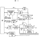
図1は、磁気記録ディスクドライブの概略ブロック図である。ディスクドライブは、磁気記録層をそれぞれ含む表面11および12を備えた、磁気記録ディスク10を包含する。ディスク10は、スピンドル6に載置され、ディスク表面11および12に垂直な軸線の周りでスピンドルモータ8によって回転される。ヘッドキャリアまたはスライダ13は、ディスク10の表面11の近傍に位置付けられる。スライダ13は、ディスク表面11に向いている空気軸受面(ABS)20および後端22を有する空気軸受スライダである。スライダ13は、その後端22上で読取り/書込みトランスデューサまたはヘッド21を支持して、ディスク表面11上の磁気媒体に対してデータの読取りおよび書込みを行う。ヘッド21は、誘導書込みエレメント、すなわちヘッド70と、MR読取りエレメント、すなわちヘッド60とを有する、デュアルエレメントヘッドである。スライダ13は、サスペンション15によってアクチュエータアーム14に取り付けられる。サスペンション15は、ディスク表面11に向かってスライダ13を付勢するばね力を提供する。読取り/書込みヘッドをやはり支持する第2のヘッドキャリアまたはスライダ17は、ディスク10の表面12上に位置付けられ、サスペンション19によってアクチュエータアーム14に取り付けられる。
FIG. 1 is a schematic block diagram of a magnetic recording disk drive. The disk drive includes a
アクチュエータアーム14は回転式アクチュエータ27に取り付けられる。アクチュエータは、典型的には、固定磁界の中で移動可能なコイルを備える回転式のボイスコイルモータ(VCM)であり、コイルの移動の方向および速度は、ハードディスク・コントローラ29から供給されるモータ電流信号によって制御される。ディスク10が回転すると、回転式アクチュエータ27は、各ディスク表面11および12の上で、ほぼアーチ形の経路でスライダ13および17を半径方向内向きおよび外向きに移動させるので、読取り/書込みヘッドは、データの読取りまたは記録が所望される磁気記録層の異なる部分にアクセスすることができる。アクチュエータ27およびスピンドルモータ8はどちらも、ディスクドライブハウジング9の一部に装着される。
The
図2は、ディスク10の表面11の上におけるスライダ13の端部の断面図である。矢印100の方向にディスク10が回転することにより、スライダ13のABSとディスク表面11の間に空気軸受が生成される。ディスクドライブの動作中、空気軸受は、サスペンションのわずかなばね力を平衡させ、スライダ13を、小さくかつ実質的に一定の間隔だけディスク表面11からわずかに離して支持する。図2はまた、読取り/書込みヘッド21、すなわち磁気抵抗(MR)読取りヘッド60および書込みヘッド70を示す。書込みヘッド70は、2つの書込み磁極72および73の間に配置されたコイル71を備えた誘導書込みヘッドである。
FIG. 2 is a cross-sectional view of the end portion of the
スライダ13は、さらに、読取り/書込みヘッド21とディスク表面11の間の間隔を変える浮上高アクチュエータを包含する。図2に示すタイプの浮上高アクチュエータは、浮上高コントローラ(FHC)82に電気的に接続され、かつそれによって制御される電気抵抗性の発熱体またはヒーター80を備えた熱アクチュエータである。FHC82は、可変抵抗器の設定を制御することなどにより、ヒーター80に対する電流または電圧の量を制御する電源である。電流が増加すると、ヒーター80は膨張し、MR読取りヘッド60と書込みヘッド70の磁極端72および73とをABSから「突出」させ、したがって、破線102で示すようにディスク表面11により近づける。FHC82は、ディスクドライブの動作中にヘッドの浮上高を所望の範囲内に維持するため、ヒーター80の温度を監視する温度フィードバック制御回路を包含してもよい。
The
熱浮上高アクチュエータは、特許文献1(米国特許第5,991,113号)および特許文献2(米国特許出願公開2005/0024775号)に記載されている。スライダに対してヘッドを移動させる他の浮上高アクチュエータとしては、特許文献3(米国特許第6,611,399号)に記載されているような静電マイクロアクチュエータ、ならびに特許文献4(米国特許第6,570,730号)に記載されているような圧電アクチュエータが挙げられる。別のタイプの浮上高アクチュエータは、スライダのABSの気流または形状を変更することによってヘッド・ディスク間隔を変える。このタイプの浮上高アクチュエータとしては、特許文献5(米国特許第6,775,103号)に記載されているような熱アクチュエータ、特許文献6(米国特許第5,276,573号)および特許文献7(米国特許第6,344,949号)に記載されているような静電アクチュエータ、ならびに特許文献8(米国特許第5,021,906号)に記載されているような圧電アクチュエータが挙げられる。 Thermal levitation height actuators are described in Patent Document 1 (US Pat. No. 5,991,113) and Patent Document 2 (US Patent Application Publication No. 2005/0024775). Other flying height actuators that move the head relative to the slider include electrostatic microactuators as described in Patent Document 3 (US Pat. No. 6,611,399), and Patent Document 4 (US Pat. 6, 570, 730). Another type of flying height actuator changes the head-disk spacing by changing the ABS airflow or shape of the slider. This type of flying height actuator includes a thermal actuator as described in Patent Document 5 (US Pat. No. 6,775,103), Patent Document 6 (US Pat. No. 5,276,573), and Patent Document 7 (U.S. Pat. No. 6,344,949), and a piezoelectric actuator as described in U.S. Pat. No. 5,021,906. .
図1を再び参照すると、ディスクドライブの様々な構成要素は、デジタルコントローラ29が生成する制御信号によって制御される。コントローラ29は、論理制御回路、記憶装置、およびマイクロプロセッサを包含するデジタル信号プロセッサである。コントローラ29は、スピンドルモータ・コントローラ30に対する電力線23上の制御信号、アクチュエータ27に対する電力線28上のトラック・フォローイングおよびトラック・シーク制御信号、ならびにFHC82に対する電力線83上の制御信号など、様々な駆動動作に対する制御信号を生成する。
Referring back to FIG. 1, the various components of the disk drive are controlled by control signals generated by the
ディスク表面11からのデータはMR読取りヘッド60で読み取られる。MR信号はアンプ37によって増幅される。アンプ37および他の読取り信号処理回路群、ならびにMR読取りヘッド60に対してセンス電流またはバイアス電流を生成する回路群は、典型的には、アクチュエータアーム14上に配置された集積回路モジュール18(図1)の一部である。モジュール18は、読取り/書込みヘッド21との相互接続をできるだけ短く維持するために、それに近接して配置され、したがってアーム電子モジュールと呼ばれる。MRアンプ37からの出力は、読取り/書込み(R/W)チャネル25に送られ、そこで、MR読取りヘッド60からのアナログ信号が、ディスク表面11の磁気記録層に記録されるデータを表すデジタル信号へと処理される。R/Wチャネル25は、典型的には、自動ゲイン制御、アナログ/デジタル変換、およびデジタルデータ検出のための回路群を包含する。
Data from the
データは、R/Wチャネル25およびライトアンプ39を介して誘導書込みヘッド70に送られた書込み信号によって、ディスク表面11の磁気記録層に書き込まれる。誘導書込みヘッド70は、記録データを表す一連の磁気転移を記録する。ライトアンプ39は、典型的にはアーム電子モジュール18内に配置される。ディスクドライブは、さらに、何らかのイベント、典型的には外部衝撃または差し迫ったヘッドクラッシュが発生すると、データの書込みを禁止する能力を包含してもよい。これは、コントローラ29からR/Wチャネル25への電力線58上の書込み禁止(WRITE INHIBIT)信号によって達成される。
Data is written to the magnetic recording layer on the
電力線28上のトラック・フォローイングおよびシーク制御信号は、入力ヘッド位置誤差信号(PES)に応じてサーボ制御アルゴリズムを実行するコントローラ29によって生成される。MR読取りヘッド60は、典型的にはデータセクタ間に埋め込まれた均等な角度を成して離間したサーボセクタにおいて、ディスクに記録されたヘッド位置サーボ情報を読取る。MRアンプ37からのこのアナログサーボ出力は、復調器38によって復調され、アナログ/デジタル(A/D)変換器40によってデジタル位置誤差信号(PES)に変換される。電力線28上のトラック・フォローイングおよびシーク制御信号は、デジタル/アナログ変換器(DAC)32に送られ、そこでアナログ電圧信号に変換され、VCMドライバ34に出力される。次に、VCMドライバ34は、対応する電流パルスをVCMアクチュエータ27のコイルに送り、VCMアクチュエータ27は、アーム14を半径方向内向きおよび外向きに旋回させて、スライダ13および17を、各ディスク表面11および12上の所望のデータトラックまで移動させ、そこに位置付ける。
The track following and seek control signals on the
本発明は、MR信号を使用して、ディスクドライブ内のヘッド・ディスク間接触(HDC)を決定するシステムおよび方法である。用語「ヘッド・ディスク接触」、すなわちHDCは、読取りヘッド60、書込みヘッド70、または後端22などのスライダのある部分が、ディスク表面11に接触していることを意味する。HDCを「決定する」という用語は、HDCの立上りを検出する、またはHDCが生じているもしくは生じようとしていると判断することを意味する。
The present invention is a system and method for determining head-to-disk contact (HDC) in a disk drive using MR signals. The term “head-disk contact” or HDC means that some portion of the slider, such as
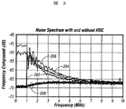
本発明は、ディスク上に磁気転移が存在することを必要としない。MR信号の振幅は、一般に約3MHz未満である低周波数で検出される。これは、記録データの周波数よりもかなり低いので、MR信号は本質的にこの低周波数でのノイズである。図3は、特定のHGA(「ヘッド・ジンバル・アセンブリ」、読取り/書込みヘッドを備えたサスペンションおよびスライダを包含するシステム)に対してヒーター80に印加された、様々なレベルの電力に対する一連のMR信号周波数スペクトルを示す。アコースティックエミッション(AE)センサは、AE信号をMR信号周波数スペクトルと相関させるために、HGAを支持するアームに載置されたものである。この例では、監視されているディスクの領域は直流消去され、したがって磁気転移を含んでいなかった。しかし、本システムおよび方法は、データが記録されたディスクにも十分に適用可能である。図3では、トレース200の群は、ヒーター電力がすべて約92mW未満であるMR信号を表し、したがってHDCを有さない。トレース202は、116mWのヒーター電力が印加された場合のMR信号を表し、1MHz未満の信号によって示されるように、HDCの立上りを示す。トレース204および206は、それぞれ113mWおよび147mWのヒーター電力レベルにおけるMR信号であり、HDCを有する周波数スペクトルである。図3では、示された周波数範囲は0〜10MHzである。ただし、重要な周波数範囲は、HGAの機械的特性に応じて約3MHz未満である。約5MHzよりも上では、HDCでのノイズレベルはHDCを有さない場合のノイズレベルと融合し、したがって、この特定のHGAについては、約5MHzを越える周波数ではMR信号はHDCを決定できないことに留意すべきである点も興味深い。
The present invention does not require that there be a magnetic transition on the disk. The amplitude of the MR signal is detected at a low frequency, which is generally less than about 3 MHz. Since this is much lower than the frequency of the recorded data, the MR signal is essentially noise at this low frequency. FIG. 3 shows a series of MRs for various levels of power applied to the
DET(ダイナミック電気試験機)としても知られるヘッド・ディスク試験機では、このシステムは、ディスクに磁気転移を記録しなくてもよいので追加のハードウェアを必要とせず、また、試験信号を書込み、かつ読取りヘッドで試験信号を検出する必要がないので、試験時間が減少されるという利点を有する。書込み電流を必要としないので、このこともまた、書込みによって誘発される磁極端の突出という潜在的な影響を排除する。さらに、MR信号は、ディスク上のヘッドの半径方向位置、ディスクのRPM、およびディスクの種類(金属基板またはガラス基板)など、他の多くの要因に対しては敏感でないため、異なるディスクドライブおよび異なるスライダ・サスペンション・アセンブリに関して、検出するのが比較的容易である。 In a head disk tester, also known as a DET (Dynamic Electrical Tester), the system does not need to record magnetic transitions on the disk, so no additional hardware is required, and a test signal is written, And since there is no need to detect the test signal at the read head, it has the advantage that the test time is reduced. This also eliminates the potential effect of pole tip protrusion induced by writing, since no write current is required. In addition, MR signals are not sensitive to many other factors such as the radial position of the head on the disk, the RPM of the disk, and the type of disk (metal substrate or glass substrate), so different disk drives and different With respect to the slider suspension assembly, it is relatively easy to detect.
本発明の方法が、ヘッド・ディスク試験機またはスピンスタンドに使用された場合、ディスクドライブ構成要素の設計を容易にする。浮上高アクチュエータを備えていないディスクドライブの場合、この方法により、特定のスライダ・サスペンション・アセンブリ、スライダ設計、および空気軸受形状を評価できるようになる。調査すべきアセンブリまたはスライダを試験機内に配置することで、上述したやり方で、HDCが決定されるまでディスクの回転速度を減少させて、スライダの浮上特性を評価することができる。浮上高アクチュエータを備えたディスクドライブの場合、この方法により、HDCが生じるFHC信号の値、例えば、熱アクチュエータに対するヒーター電力を決定することによって、特定の浮上高アクチュエータを評価できるようになる。また、この方法は、データが記録されたディスクおよび記録されていないディスクに適用可能なので、磁気記録層を有さないディスクにもこの方法を使用することができる。 When the method of the present invention is used in a head disk tester or spinstand, it facilitates the design of disk drive components. For disk drives that do not have a flying height actuator, this method allows the evaluation of a specific slider suspension assembly, slider design, and air bearing geometry. By placing the assembly or slider to be investigated in the tester, the flying characteristics of the slider can be evaluated in the manner described above by reducing the rotational speed of the disk until the HDC is determined. For disk drives with flying height actuators, this method allows a particular flying height actuator to be evaluated by determining the value of the FHC signal generated by the HDC, eg, the heater power for the thermal actuator. Further, since this method can be applied to a disk on which data is recorded and a disk on which data is not recorded, this method can also be used for a disk having no magnetic recording layer.
図3に示すデータは、XY位置決めを備えた日立ハイテク電子エンジニアリング株式会社(Hitachi DECO)製のRH−4160E DETなどの、ヘッド・ディスク試験機またはスピンスタンドを使用して、MR信号を、DETの内部スペクトルアナライザ、または市販の外部スペクトルアナライザもしくはデジタルオシロスコープのいずれかに入力して蓄積された。他のタイプのスピンスタンドとしては、ガジック・テクニカル・エンタープライズ(Guzik Technical Enterprises)製のGuzikモデルV2002XY位置決めスピンスタンドが挙げられる。ルクロイ社(LeCroy Corporation)から入手可能なものなどの、デジタルオシロスコープおよびデジタルディスクドライブアナライザは、アナログ/デジタル変換器(ADC)でMR信号をデジタル化して、マイクロプロセッサのメモリに格納されるデータセットを作成する。データセットは処理され、ディスプレイに送られる。さらに、デジタル信号の複雑な処理は、高速デジタル信号処理回路によって行うことができる。オシロスコープまたはアナライザは、多くの有用な時間領域機能(例えば、立上り時間、パルス幅、振幅)、周波数スペクトル、および他のパラメータを抽出することができ、したがって所望の周波数範囲内のMR信号振幅を計算することができる、プログラム可能な信号解析ソフトウェアを包含する。 The data shown in FIG. 3 is obtained by using a head disk tester or spin stand such as RH-4160E DET manufactured by Hitachi High-Tech Electronics Engineering Co., Ltd. (Hitachi DECO) equipped with XY positioning. It was input and stored in either an internal spectrum analyzer, or a commercially available external spectrum analyzer or digital oscilloscope. Another type of spinstand is the Guzik model V2002XY positioning spinstand manufactured by Guzik Technical Enterprises. Digital oscilloscopes and digital disk drive analyzers, such as those available from LeCroy Corporation, digitize MR signals with an analog-to-digital converter (ADC) to produce a data set stored in microprocessor memory. create. The data set is processed and sent to the display. Furthermore, complicated processing of digital signals can be performed by a high-speed digital signal processing circuit. The oscilloscope or analyzer can extract many useful time domain functions (eg, rise time, pulse width, amplitude), frequency spectrum, and other parameters, thus calculating the MR signal amplitude within the desired frequency range Includes programmable signal analysis software that can.
しかし、本発明の方法は、ディスクドライブに組み入れることもできる。図4に示すように、MRアンプ37からのMR信号は、3MHz未満の周波数のみを通過させる低域フィルタ(LPF)102に送られる。LPF出力104は、所定の閾値を表す固定の入力105も有するコンパレータ回路106に入力される。コンパレータ出力108は、アナログ/デジタル変換器(ADC)110に、次にデジタルコントローラ29に入力される。MR信号振幅104が閾値105よりも大きい場合、コンパレータ出力108はHDCを表す。次の表1は、様々なレベルのヒーター電力に対する正規化されたLPF102からの出力を示しており、ヒーター電力ゼロ(HDC無し)に対するLPF出力は1.00である。
However, the method of the present invention can also be incorporated into a disk drive. As shown in FIG. 4, the MR signal from the

閾値は、表1に示すデータに基づいて選択することができる。例えば、HDCでのMR信号が第1の振幅(約4)で、HDCを有さないMR信号が第2の振幅(1.0)である場合、閾値は、第1および第2の振幅の差の何%か、例えば25%であるように選択され、第2の振幅に加算されることができる。したがって、この特定のHGAに対する本例において、閾値は、1.00に差(3.0)の25%を加えたもの、すなわち1.75となるので、MR信号が1.75よりも大きければ、それはHDCを示す。別の方法として、表1から分かるように、HDCにおけるLPF出力には、突然のほぼ階段状の増加がある。したがって、特定のHGAに対して十分なデータサンプルが得られた場合、閾値は、データを検査することによって直接決定することができる。この方法を用いて、表1を検査することにより、閾値を約1.5に設定できることが示される。 The threshold value can be selected based on the data shown in Table 1. For example, if the MR signal at the HDC has the first amplitude (about 4) and the MR signal without HDC has the second amplitude (1.0), the threshold value is the first and second amplitudes. It can be selected to be some percent of the difference, for example 25%, and added to the second amplitude. Thus, in this example for this particular HGA, the threshold is 1.00 plus 25% of the difference (3.0), ie 1.75, so if the MR signal is greater than 1.75. , It indicates HDC. Alternatively, as can be seen from Table 1, there is a sudden, almost step-like increase in LPF output in HDC. Thus, if sufficient data samples are obtained for a particular HGA, the threshold can be determined directly by examining the data. Using this method, examining Table 1 shows that the threshold can be set to about 1.5.
図4は、システムのアナログの具体例を示す。ただし、本発明はデジタル技術を用いて実現することもできる。デジタルオシロスコープまたはディスクドライブアナライザによって行われるのと同じデジタル信号処理技術およびデータ解析を、コントローラ29にプログラムすることができる。したがって、コントローラ29は、R/Wチャネル25からのデジタル化されたMR信号を解析し、計算された振幅を所定の閾値と比較する。これは、ディスクドライブ用のマイクロコード(ファームウェア)またはDET試験機用のカスタムモジュールによって実現することができる。
FIG. 4 shows an analog example of the system. However, the present invention can also be realized using digital technology. The same digital signal processing techniques and data analysis performed by a digital oscilloscope or disk drive analyzer can be programmed into the
いずれの具体例においても、HDCが決定されると、コントローラ29は1つまたは複数の信号を生成して、修正動作を行う。一実施例では、電力線58上の信号は、差し迫ったヘッドクラッシュのため書込みヘッド70がデータを書込むのを防止する、R/Wチャネル25に送られる「書込み禁止」信号である。別の実施例では、電力線83上の信号は、ヒーター電力を減少させてヘッドをディスクから離れる方向に移動させるように、FHC82に報知する。
In any embodiment, once the HDC is determined, the
好ましい実施形態に関して本発明を特定して示し、記載してきたが、本発明の趣旨および範囲から逸脱することなく形態および詳細を様々に変更してもよいことが、当業者には理解されるであろう。したがって、開示される発明は単に例示目的のものであり、その範囲は、添付の特許請求の範囲に明記されるものによってのみ限定されるものと見なされる。 While the invention has been particularly shown and described with respect to preferred embodiments, those skilled in the art will appreciate that various changes in form and detail may be made without departing from the spirit and scope of the invention. I will. Accordingly, the disclosed invention is to be considered merely as illustrative and limited in scope only as set forth in the appended claims.
6…スピンドル、
8…スピンドルモータ、
9…ディスクドライブハウジング、
10…磁気記録ディスク、
11、12…ディスク表面、
13、17…スライダ、
14…アクチュエータアーム、
15、19…サスペンション、
18…集積回路モジュール、
20…空気軸受面(ABS)、
21…読取り/書込みヘッド、
22…後端、
23、28、58…電力線、
25…読取り/書込み(R/W)チャネル、
27…VCMアクチュエータ、
29…ハードディスク・コントローラ、
30…スピンドルモータ・コントローラ、
32…デジタル/アナログ変換器(DAC)、
34…VCMドライバ、
37…アンプ、
38…復調器、
39…ライトアンプ、
40…アナログ/デジタル(A/D)変換器、
60…磁気抵抗(MR)読取りヘッド、
70…書込みヘッド、
71…コイル、
72、73…書込み磁極、
80…ヒーター、
82…浮上高コントローラ(FHC)、
102…低域フィルタ(LPF)、
106…コンパレータ回路、
110…アナログ/デジタル変換器(ADC)。
6 ... Spindle,
8 ... Spindle motor,
9: Disc drive housing,
10: Magnetic recording disk,
11, 12 ... disk surface,
13, 17 ... slider,
14 ... Actuator arm,
15, 19 ... suspension,
18 ... integrated circuit module,
20: Air bearing surface (ABS),
21 ... Read / write head,
22 ... Rear end,
23, 28, 58 ... power lines,
25 ... Read / write (R / W) channel,
27 ... VCM actuator,
29 ... Hard disk controller,
30 ... Spindle motor controller
32. Digital / analog converter (DAC),
34 ... VCM driver,
37 ... Amplifier,
38 ... demodulator,
39 ... Light amplifier,
40. Analog / digital (A / D) converter,
60 ... Magnetoresistive (MR) read head,
70: writing head,
71 ... Coil,
72, 73 ... write magnetic pole,
80 ... Heater,
82 ... Flying height controller (FHC),
102 ... Low-pass filter (LPF),
106: Comparator circuit,
110: Analog / digital converter (ADC).
Claims (18)
前記ディスク表面に実質的に垂直な軸線の周りで前記ディスクを回転させる工程と、
前記空気軸受スライダを前記回転するディスクの前記表面の近傍で維持する工程と、
約0〜3MHzの周波数範囲全体にわたって前記ヘッドからのMR信号の振幅を検出する工程と、
前記検出された振幅が所定の閾値よりも大きいとき、HDCを決定する工程と、を含む方法。 A magnetic recording disk, an air bearing slider maintained near the surface of the rotating disk, a magnetoresistive (MR) read head on the slider, and a head flying height actuator that varies the spacing between the head and the disk surface A method for determining head-disk contact (HDC) in a magnetic recording disk drive comprising:
Rotating the disk about an axis substantially perpendicular to the disk surface;
Maintaining the air bearing slider in the vicinity of the surface of the rotating disk;
Detecting the amplitude of the MR signal from the head over the entire frequency range of about 0-3 MHz;
Determining HDC when the detected amplitude is greater than a predetermined threshold.
前記ディスクが回転しているとき、前記ディスクの表面の近傍で維持される空気軸受スライダと、
前記スライダ上の磁気抵抗(MR)読取りヘッドと、
前記読取りヘッドと前記ディスク表面の間の間隔を変える浮上高アクチュエータと、
約3MHz未満の周波数で前記読取りヘッドからのMR信号の振幅を検出するフィルタと、
前記フィルタの出力側に接続された、前記MR信号振幅を閾値と比較するコンパレータであって、その出力側がHDCを表す、またはHDCがないことを表すコンパレータと、
を備えるヘッド・ディスク間接触(HDC)を決定するシステム。 A rotatable magnetic recording disk;
An air bearing slider maintained near the surface of the disk when the disk is rotating;
A magnetoresistive (MR) read head on the slider;
A flying height actuator that changes the spacing between the read head and the disk surface;
A filter for detecting the amplitude of the MR signal from the read head at a frequency of less than about 3 MHz;
A comparator connected to the output side of the filter for comparing the MR signal amplitude with a threshold value, the output side representing HDC or no HDC;
A system for determining head-disk contact (HDC) comprising:
Applications Claiming Priority (1)
| Application Number | Priority Date | Filing Date | Title |
|---|---|---|---|
| US11/376,660 US7292401B2 (en) | 2006-03-14 | 2006-03-14 | System and method for determining head-disk contact in a magnetic recording disk drive by magnetoresistive signal amplitude |
Publications (2)
| Publication Number | Publication Date |
|---|---|
| JP2007250170A true JP2007250170A (en) | 2007-09-27 |
| JP2007250170A5 JP2007250170A5 (en) | 2010-03-25 |
Family
ID=38517519
Family Applications (1)
| Application Number | Title | Priority Date | Filing Date |
|---|---|---|---|
| JP2007063507A Pending JP2007250170A (en) | 2006-03-14 | 2007-03-13 | System and method of determining head-disk contact in magnetic recording disk drive by magnetic resistance signal amplitude |
Country Status (3)
| Country | Link |
|---|---|
| US (1) | US7292401B2 (en) |
| JP (1) | JP2007250170A (en) |
| CN (1) | CN101038769A (en) |
Cited By (4)
| Publication number | Priority date | Publication date | Assignee | Title |
|---|---|---|---|---|
| JP2011065719A (en) * | 2009-09-17 | 2011-03-31 | Hitachi Global Storage Technologies Netherlands Bv | Head slider and magnetic disk device |
| JP2011210358A (en) * | 2010-03-26 | 2011-10-20 | Samsung Electronics Co Ltd | Method and device for detecting touchdown and contact between head and medium in data storage device, disk drive and recording medium adopting the same |
| JP2021101400A (en) * | 2019-12-24 | 2021-07-08 | 株式会社東芝 | Magnetic disk device |
| US11887634B2 (en) | 2022-03-24 | 2024-01-30 | Kabushiki Kaisha Toshiba | Magnetic disk device and control method of magnetic disk device |
Families Citing this family (38)
| Publication number | Priority date | Publication date | Assignee | Title |
|---|---|---|---|---|
| JP4255869B2 (en) * | 2004-03-24 | 2009-04-15 | ヒタチグローバルストレージテクノロジーズネザーランドビーブイ | Magnetic disk drive and magnetic head slider used therefor |
| JP2007066460A (en) * | 2005-09-01 | 2007-03-15 | Hitachi Global Storage Technologies Netherlands Bv | Magnetic head evaluating apparatus, and manufacturing method of magnetic disk apparatus using it |
| US7558015B2 (en) * | 2006-03-29 | 2009-07-07 | Maxtor Corporation | Actuation efficiency based contact detection |
| US7423830B2 (en) * | 2006-04-10 | 2008-09-09 | Iomega Corporation | Detecting head/disk contact in a disk drive using a calibration parameter |
| JP2007293948A (en) * | 2006-04-21 | 2007-11-08 | Fujitsu Ltd | Information recording and reproducing device, head floating height control method, head floating control circuit |
| US7508616B2 (en) * | 2006-05-18 | 2009-03-24 | Seagate Technology Llc | Regulating data writes responsive to head fly height |
| US20070291401A1 (en) * | 2006-05-19 | 2007-12-20 | Maxtor Corporation | Contact detection using calibrated seeks |
| JP2008047241A (en) * | 2006-08-18 | 2008-02-28 | Tdk Corp | Floating height measurement method and magnetic disk drive capable of adjusting floating height |
| US20080055772A1 (en) * | 2006-09-01 | 2008-03-06 | Mcmillan Chris | Method and apparatus for predicting contact of a read-write head in a hard disk drive |
| US20080088962A1 (en) * | 2006-10-17 | 2008-04-17 | Samsung Electronics Co., Ltd. | Detection of HDI in disk drives using read back signal |
| US20080291564A1 (en) * | 2007-05-25 | 2008-11-27 | Samsung Electronics Co., Ltd. | Detecting head-disk contact during off-track operations |
| JP2008293625A (en) * | 2007-05-28 | 2008-12-04 | Hitachi Global Storage Technologies Netherlands Bv | Apparatus and method for determining control value to control clearance between head and disk, and magnetic disk drive device |
| JP2009032325A (en) * | 2007-07-26 | 2009-02-12 | Fujitsu Ltd | Storage device, control method, and control unit |
| US7583466B2 (en) * | 2007-11-15 | 2009-09-01 | Western Digital (Fremont), Llc | Disk drive determining operating fly height by detecting head disk contact from disk rotation time |
| US7724461B1 (en) * | 2007-12-21 | 2010-05-25 | Western Digital Technologies, Inc. | Determining head non-linearity in a disk drive |
| US7933085B2 (en) * | 2008-03-31 | 2011-04-26 | Hitachi Global Storage Technologies Netherlands, B.V. | Head spacing verification in magnetic disk drive systems during end-user operation |
| US7920346B2 (en) * | 2008-05-21 | 2011-04-05 | Sae Magnetics (H.K.) Ltd. | Method for testing performance of a magnetic head slider |
| US7965459B2 (en) * | 2008-12-18 | 2011-06-21 | Seagate Technology Llc | Wavelets-based detection of proximity between a sensor and an object |
| US20100157765A1 (en) | 2008-12-19 | 2010-06-24 | Seagate Technology Llc | Collection of readback signal modulation data |
| US7719786B1 (en) * | 2008-12-23 | 2010-05-18 | Hitachi Global Storage Technologies Netherlands B.V. | Active fly height control using radio frequency feedback |
| US7830634B2 (en) * | 2008-12-23 | 2010-11-09 | Hitachi Global Storage Technologies Netherlands, B.V. | Head-disk contact detection and work function difference determination |
| US7889447B2 (en) * | 2009-01-14 | 2011-02-15 | Seagate Technology Llc | Readback signal-based head-disc contact detection using AM/FM demodulation |
| US8665546B1 (en) | 2010-01-07 | 2014-03-04 | Western Digital Technologies, Inc. | Adaptive threshold for detecting touchdown or contamination |
| KR20110108180A (en) * | 2010-03-26 | 2011-10-05 | 삼성전자주식회사 | Method for detecting touch-down of head and head flying height adjusting method and disk drive using the same |
| US8730611B2 (en) | 2011-02-28 | 2014-05-20 | Seagate Technology Llc | Contact detection |
| CN102280112B (en) * | 2011-04-13 | 2013-12-18 | 华中科技大学 | Thermal flying-height control slider for hard disk drive |
| US9053740B1 (en) | 2011-05-04 | 2015-06-09 | Western Digital Technologies, Inc. | Disk drive determining touchdown threshold |
| US8643981B2 (en) * | 2011-12-28 | 2014-02-04 | HGST Netherlands B. V. | Magnetic domain control for an embedded contact sensor for a magnetic recording head |
| US8611036B2 (en) * | 2012-05-06 | 2013-12-17 | HGST Netherlands B.V. | Disk drive with head thermal fly-height actuator and controller for compensation of write head expansion |
| US8797671B2 (en) | 2012-05-17 | 2014-08-05 | HGST Netherlands B.V. | Excitation of airbearing oscillation with tar nearfield device for touchdown detection |
| US8582231B1 (en) | 2012-06-06 | 2013-11-12 | Western Digital Technologies, Inc. | Disk drive determining head touchdown threshold based on curve fitting prediction error |
| US20140063644A1 (en) * | 2012-08-29 | 2014-03-06 | Seagate Technology Llc | Magnetic Element with Multiple Selective Transducing Elements |
| US8891193B1 (en) | 2013-05-09 | 2014-11-18 | Western Digital Technologies, Inc. | Disk drive calibrating threshold and gain of touchdown sensor |
| US9214186B1 (en) | 2015-03-23 | 2015-12-15 | Western Digital Technologies, Inc. | Data storage device measuring radial offset between read element and write element |
| US9373346B1 (en) | 2015-06-27 | 2016-06-21 | International Business Machines Corporation | Adjustable spacing formatter head |
| US11875830B2 (en) | 2021-02-10 | 2024-01-16 | Seagate Technology Llc | Adjusting HGA z-height via HSA elevator using head/actuator feedback |
| US11315592B1 (en) | 2021-02-10 | 2022-04-26 | Seagate Technology Llc | Adjusting HGA z-height via HSA elevator using head/actuator feedback |
| US11900965B2 (en) | 2022-02-14 | 2024-02-13 | Seagate Technology Llc | Z-height control for disc drive using servo wedge timing |
Citations (2)
| Publication number | Priority date | Publication date | Assignee | Title |
|---|---|---|---|---|
| JPH0944979A (en) * | 1995-07-31 | 1997-02-14 | Toshiba Corp | Disk recording and reproducing device and head collision detecting device to be applied to the same device |
| JPH10188248A (en) * | 1996-09-19 | 1998-07-21 | Hitachi Ltd | Servo signal processing circuit and magnetic disk device using it |
Family Cites Families (48)
| Publication number | Priority date | Publication date | Assignee | Title |
|---|---|---|---|---|
| US5021906A (en) | 1989-10-31 | 1991-06-04 | International Business Machines Corporation | Programmable air bearing slider including magnetic read/write element |
| US5130866A (en) | 1990-07-17 | 1992-07-14 | International Business Machines Corporation | Method and circuitry for in-situ measurement of transducer/recording medium clearance and transducer magnetic instability |
| JP2884774B2 (en) | 1990-12-01 | 1999-04-19 | 株式会社日立製作所 | Information storage device and its manufacturing method |
| US5455730A (en) | 1993-02-18 | 1995-10-03 | International Business Machines Corporation | Contact magnetic recording disk file with a magnetoresistive read sensor |
| US6088176A (en) * | 1993-04-30 | 2000-07-11 | International Business Machines Corporation | Method and apparatus for separating magnetic and thermal components from an MR read signal |
| US5777815A (en) * | 1996-06-13 | 1998-07-07 | International Business Machines Corporation | Disk drive with shock detection based on thermoresistive signal from magnetoresistive head |
| US5909330A (en) | 1996-12-12 | 1999-06-01 | Maxtor Corporation | Method and apparatus for detecting head flying height in a disk drive |
| US5991113A (en) | 1997-04-07 | 1999-11-23 | Seagate Technology, Inc. | Slider with temperature responsive transducer positioning |
| US6735027B2 (en) | 1998-06-02 | 2004-05-11 | Texas Instruments Incorporated | Head fly height by using the applied peak area ratio to determine signal PW50 |
| US6275345B1 (en) | 1998-12-02 | 2001-08-14 | International Business Machines Corporation | System and method for estimating a frequency of slider airbearing resonance |
| US6570730B1 (en) * | 1999-06-09 | 2003-05-27 | Seagate Technology, Llc. | Shear-based transducer for HDD read/write element height control |
| US6344949B1 (en) | 1999-07-13 | 2002-02-05 | International Business Machines Corporation | Flying height adjustment for air bearing sliders |
| US6452735B1 (en) * | 1999-07-19 | 2002-09-17 | Maxtor Corporation | Disk drive that monitors the flying height of a dual element transducer using a thermally induced signal during write operations |
| US6417981B1 (en) * | 1999-09-23 | 2002-07-09 | International Business Machines Corporation | System and method for measuring absolute transducer-medium clearance using a thermal response of an MR transducer |
| WO2001041132A2 (en) * | 1999-12-02 | 2001-06-07 | Seagate Technology Llc | Fly height control over patterned media |
| JP3647708B2 (en) | 2000-02-09 | 2005-05-18 | ヒタチグローバルストレージテクノロジーズネザーランドビーブイ | Magnetic head flying height abnormality detection method, data writing method, and hard disk drive device |
| US6600622B1 (en) * | 2000-02-11 | 2003-07-29 | Hitachi Global Storage Technologies Netherlands B.V. | System and method for detecting displacement of disk drive heads on micro actuators due to contact with disks |
| US6407874B1 (en) | 2000-03-30 | 2002-06-18 | International Business Machines Corporation | Method and apparatus for detection slider airbearing resonance using SAT P-list data |
| US6479988B2 (en) * | 2000-06-06 | 2002-11-12 | Tdk Corporation | Method and apparatus for testing thin-film magnetic head |
| US6611399B1 (en) | 2000-12-07 | 2003-08-26 | Seagate Technology Llc | Micro-actuated micro-suspension(MAMS) slider for both fly height and tracking position |
| US6717776B2 (en) | 2001-01-19 | 2004-04-06 | Seagate Technology Llc | Adjustable fly height control using an adjustable head actuator assembly |
| US6785079B2 (en) | 2001-03-16 | 2004-08-31 | Hitachi Global Storage Technologies Netherlands B.V. | Method and apparatus for estimating the flyheight of an airbearing slider in a storage device |
| US6775103B2 (en) | 2001-04-02 | 2004-08-10 | Hitachi Global Storage Technologies Netherlands B.V. | Slider head having thermally controlled distal end and assembly with a rotating disc |
| WO2002095738A1 (en) | 2001-05-22 | 2002-11-28 | Seagate Technology Llc | Method and system for measuring fly height |
| US6801376B2 (en) * | 2001-06-21 | 2004-10-05 | Hitachi Global Storage Technologies Netherlands B.V. | Method and apparatus for evaluating a head-disk interface condition for disk drives |
| US6898034B2 (en) | 2001-10-10 | 2005-05-24 | Seagate Technology Llc | Fly height measurement for a disc drive |
| US6765745B2 (en) | 2001-12-28 | 2004-07-20 | Hitachi Global Storage Technologies Netherlands, B.V. | Method and apparatus for in situ detection of high-flying sliders over customer data |
| US7486457B2 (en) * | 2002-02-15 | 2009-02-03 | Hitachi Global Storage Technologies Netherlands B.V. | Method and apparatus for predicting write failure resulting from flying height modulation |
| KR100468766B1 (en) | 2002-09-19 | 2005-01-29 | 삼성전자주식회사 | Method for controlling flying height between head and disk and apparatus thereof |
| JP3626954B2 (en) | 2003-03-12 | 2005-03-09 | Tdk株式会社 | Thin-film magnetic head manufacturing method, thin-film magnetic head, head gimbal assembly, and hard disk device |
| JP2004335069A (en) | 2003-04-14 | 2004-11-25 | Tdk Corp | Thin film magnetic head, head gymbal assembly, and hard disk device |
| US6940691B2 (en) | 2003-04-30 | 2005-09-06 | Hitachi Global Storage Technologies Netherlands B.V. | Electrically resistive heating device for data storage systems |
| US7133254B2 (en) | 2003-05-30 | 2006-11-07 | Hitachi Global Storage Technologies Netherlands B.V. | Magnetic recording head with heating device |
| US7038875B2 (en) | 2003-07-31 | 2006-05-02 | Seagate Technology Llc | Dynamic measurement of head media spacing modulation |
| JP4072469B2 (en) | 2003-08-01 | 2008-04-09 | 株式会社日立グローバルストレージテクノロジーズ | Magnetic head slider and magnetic disk apparatus |
| JP4223897B2 (en) | 2003-08-28 | 2009-02-12 | ヒタチグローバルストレージテクノロジーズネザーランドビーブイ | A magnetic disk device with a function that uses the amount of thermal resolution for flying height management, and an inspection device with that function. |
| US7016131B2 (en) | 2003-08-29 | 2006-03-21 | Agency For Science, Technology And Research | Method and implementation of in-situ absolute head medium spacing measurement |
| US6947246B2 (en) | 2003-08-29 | 2005-09-20 | Hitachi Global Storage Technologies Netherlands, B.V. | Large protrusion recording head for controlled magnetic spacing recording/reading |
| US7054084B2 (en) | 2003-08-29 | 2006-05-30 | Hitachi Global Storage Technologies Netherlands B.V. | Method, apparatus and program storage device for sensing increased resistance changes in an MR element to detect MR sensor events |
| US6972919B2 (en) | 2003-09-05 | 2005-12-06 | Hitachi Global Storage Technologies Netherlands, B.V. | Increasing head-disk interface reliability using controlled heating |
| US6975472B2 (en) | 2003-09-12 | 2005-12-13 | Seagate Technology Llc | Head with heating element and control regime therefor |
| US20050094303A1 (en) | 2003-11-04 | 2005-05-05 | Tom Chan | Flying height monitor with servo AGC voltage for write operation in a hard disk drive |
| JP4131950B2 (en) | 2003-11-04 | 2008-08-13 | ヒタチグローバルストレージテクノロジーズネザーランドビーブイ | Rotating disk storage device |
| US8531796B2 (en) * | 2004-01-09 | 2013-09-10 | International Business Machines Corporation | Fly height extraction system |
| US7119979B2 (en) * | 2004-06-30 | 2006-10-10 | Hitachi Global Storage Technologies Netherlands B.V. | Measurement of slider clearance by inducing collision of the slider with disk surface |
| JP2006252593A (en) * | 2005-03-08 | 2006-09-21 | Hitachi Global Storage Technologies Netherlands Bv | Magnetic disk device, control method and manufacturing method thereof |
| US7180692B1 (en) * | 2005-12-27 | 2007-02-20 | Hitachi Global Storage Technologies Netherlands B.V. | System and method for calibrating and controlling a fly-height actuator in a magnetic recording disk drive |
| US7215495B1 (en) * | 2005-12-27 | 2007-05-08 | Hitachi Global Storage Technologies Netherlands B.V. | System and method for determining head-disk contact in a magnetic recording disk drive |
-
2006
- 2006-03-14 US US11/376,660 patent/US7292401B2/en not_active Expired - Fee Related
-
2007
- 2007-03-13 JP JP2007063507A patent/JP2007250170A/en active Pending
- 2007-03-14 CN CN200710085774.9A patent/CN101038769A/en active Pending
Patent Citations (2)
| Publication number | Priority date | Publication date | Assignee | Title |
|---|---|---|---|---|
| JPH0944979A (en) * | 1995-07-31 | 1997-02-14 | Toshiba Corp | Disk recording and reproducing device and head collision detecting device to be applied to the same device |
| JPH10188248A (en) * | 1996-09-19 | 1998-07-21 | Hitachi Ltd | Servo signal processing circuit and magnetic disk device using it |
Cited By (5)
| Publication number | Priority date | Publication date | Assignee | Title |
|---|---|---|---|---|
| JP2011065719A (en) * | 2009-09-17 | 2011-03-31 | Hitachi Global Storage Technologies Netherlands Bv | Head slider and magnetic disk device |
| JP2011210358A (en) * | 2010-03-26 | 2011-10-20 | Samsung Electronics Co Ltd | Method and device for detecting touchdown and contact between head and medium in data storage device, disk drive and recording medium adopting the same |
| JP2021101400A (en) * | 2019-12-24 | 2021-07-08 | 株式会社東芝 | Magnetic disk device |
| JP7293105B2 (en) | 2019-12-24 | 2023-06-19 | 株式会社東芝 | magnetic disk device |
| US11887634B2 (en) | 2022-03-24 | 2024-01-30 | Kabushiki Kaisha Toshiba | Magnetic disk device and control method of magnetic disk device |
Also Published As
| Publication number | Publication date |
|---|---|
| US7292401B2 (en) | 2007-11-06 |
| CN101038769A (en) | 2007-09-19 |
| US20070217051A1 (en) | 2007-09-20 |
Similar Documents
| Publication | Publication Date | Title |
|---|---|---|
| US7292401B2 (en) | System and method for determining head-disk contact in a magnetic recording disk drive by magnetoresistive signal amplitude | |
| US7215495B1 (en) | System and method for determining head-disk contact in a magnetic recording disk drive | |
| US7180692B1 (en) | System and method for calibrating and controlling a fly-height actuator in a magnetic recording disk drive | |
| US8711508B2 (en) | Contact detection between a disk and magnetic head | |
| US7423830B2 (en) | Detecting head/disk contact in a disk drive using a calibration parameter | |
| JP3723651B2 (en) | Method and apparatus for restoring the thermal response of a magnetoresistive head | |
| US6452735B1 (en) | Disk drive that monitors the flying height of a dual element transducer using a thermally induced signal during write operations | |
| US8619529B1 (en) | Methods and devices for enhanced adaptive margining based on channel threshold measure | |
| US7489466B2 (en) | Enabling intermittent contact recording on-demand | |
| US6611397B1 (en) | Servo burst pattern defect detection | |
| US8416521B2 (en) | Magnetic recording and reproduction device and flying height control method | |
| US20050129090A1 (en) | Temperature compensation systems and methods for use with read/write heads in magnetic storage devices | |
| US7656600B2 (en) | Monitoring transducer potential to detect an operating condition | |
| JPH10134492A (en) | Disk drive equipped with impact detecting mechanism based on thermal resistance signal from magneto-resistance head | |
| US20080165443A1 (en) | Method and device for compensating for thermal decay in a magnetic storage device | |
| US9595280B2 (en) | Hard disk drive head-disk interface dithering | |
| US20060132961A1 (en) | Detection of fly height change in a disk drive using head drag | |
| US20030184899A1 (en) | Low flying head detection using readback signal amplitude modulation | |
| US10395678B1 (en) | Method and system for determining slider-disk contact in a magnetic recording disk drive with dual fly-height actuators | |
| US8804275B1 (en) | System and method for determining head-disk contact in a magnetic recording disk drive having a fly-height actuator | |
| US20100309574A1 (en) | Detecting ramp load/unload operations | |
| KR100571757B1 (en) | Low amplitude skip write detector | |
| US6611389B1 (en) | Method of determining the variation of the clearance between a magnetic transducer and a recording media during track seeking | |
| US20140240871A1 (en) | Interface voltage control operating point determination in a hard disk drive | |
| US20030030934A1 (en) | In-situ detection of transducer magnetic instability in a disc drive |
Legal Events
| Date | Code | Title | Description |
|---|---|---|---|
| A521 | Written amendment |
Free format text: JAPANESE INTERMEDIATE CODE: A523 Effective date: 20100208 |
|
| A621 | Written request for application examination |
Free format text: JAPANESE INTERMEDIATE CODE: A621 Effective date: 20100208 |
|
| A977 | Report on retrieval |
Free format text: JAPANESE INTERMEDIATE CODE: A971007 Effective date: 20110520 |
|
| A131 | Notification of reasons for refusal |
Free format text: JAPANESE INTERMEDIATE CODE: A131 Effective date: 20110607 |
|
| A02 | Decision of refusal |
Free format text: JAPANESE INTERMEDIATE CODE: A02 Effective date: 20111101 |