JP2007222613A - Method of controlling vacuum cleaner - Google Patents
Method of controlling vacuum cleaner Download PDFInfo
- Publication number
- JP2007222613A JP2007222613A JP2007019770A JP2007019770A JP2007222613A JP 2007222613 A JP2007222613 A JP 2007222613A JP 2007019770 A JP2007019770 A JP 2007019770A JP 2007019770 A JP2007019770 A JP 2007019770A JP 2007222613 A JP2007222613 A JP 2007222613A
- Authority
- JP
- Japan
- Prior art keywords
- dust
- vacuum cleaner
- controlling
- pressure member
- cleaner according
- Prior art date
- Legal status (The legal status is an assumption and is not a legal conclusion. Google has not performed a legal analysis and makes no representation as to the accuracy of the status listed.)
- Pending
Links
Images


Classifications
-
- A—HUMAN NECESSITIES
- A47—FURNITURE; DOMESTIC ARTICLES OR APPLIANCES; COFFEE MILLS; SPICE MILLS; SUCTION CLEANERS IN GENERAL
- A47L—DOMESTIC WASHING OR CLEANING; SUCTION CLEANERS IN GENERAL
- A47L9/00—Details or accessories of suction cleaners, e.g. mechanical means for controlling the suction or for effecting pulsating action; Storing devices specially adapted to suction cleaners or parts thereof; Carrying-vehicles specially adapted for suction cleaners
- A47L9/10—Filters; Dust separators; Dust removal; Automatic exchange of filters
- A47L9/106—Dust removal
- A47L9/108—Dust compression means
Abstract
Description
本発明は、真空掃除機の制御方法に関し、詳細には、集塵装置の集塵容量が増加するようにし、集塵された塵埃の排出を容易にする真空掃除機の制御方法に関する。 The present invention relates to a method for controlling a vacuum cleaner, and more particularly to a method for controlling a vacuum cleaner that increases the dust collection capacity of a dust collector and facilitates the discharge of the collected dust.
一般に、真空掃除機は、本体の内部に装着される吸入モータによって発生する真空圧を利用して、塵埃が含まれている空気を吸入した後、本体の内部で塵埃をフィルタリングする装置である。
かかる真空掃除機は、大きく吸入口であるノズル部が本体と別途に備えられて、連結管によって連結されるキャニスタ方式と、ノズル部が本体と一体に形成されるアップライト方式に区別することができる。
In general, a vacuum cleaner is a device that filters the dust inside the main body after inhaling air containing dust using a vacuum pressure generated by a suction motor mounted inside the main body.
In such a vacuum cleaner, a nozzle part, which is a large suction port, is provided separately from the main body, and can be classified into a canister type connected by a connecting pipe and an upright type in which the nozzle part is formed integrally with the main body. it can.
一方、サイクロン方式の真空掃除機に装着される集塵装置は、サイクロン原理を利用して、吸入された空気中に含まれて共に回転される塵埃が空気から分離収集されるようにし、塵埃が除去された空気は、掃除機の外部に排出されるようにした装置である。
詳細には、サイクロン集塵装置は、集塵体と、集塵体に空気が吸入されるようにする吸入口と、集塵体に吸入される空気の中から塵埃を分離させるサイクロン部と、サイクロン部から分離された塵埃が捕集される塵埃捕集部と、サイクロン部から塵埃が分離された空気が排出される排出口とが備えられる。
On the other hand, a dust collector attached to a cyclone vacuum cleaner uses the cyclone principle so that dust contained in the sucked air and rotated together is separated and collected from the air. The removed air is a device that is discharged outside the vacuum cleaner.
Specifically, the cyclone dust collector includes a dust collector, a suction port that allows air to be sucked into the dust collector, a cyclone unit that separates dust from the air sucked into the dust collector, A dust collecting part for collecting dust separated from the cyclone part and an exhaust port for discharging air from which the dust is separated from the cyclone part are provided.
一方、集塵体の下部空間、すなわち、塵埃捕集部に捕集された塵埃は、真空掃除機が作動する間は、集塵体の内部の回転流により、集塵体の内周面に沿って回転運動し続ける。
そして、真空掃除機の作動が停止すると、集塵体の底面にそのまま沈んで、密度の低い状態で捕集される。
On the other hand, the dust collected in the lower space of the dust collector, i.e., the dust collector, is moved to the inner peripheral surface of the dust collector by the rotational flow inside the dust collector while the vacuum cleaner operates. Continue to rotate along.
Then, when the operation of the vacuum cleaner stops, it sinks as it is on the bottom surface of the dust collector and is collected in a low density state.
したがって、従来の集塵装置は、真空掃除機が作動する中で、集塵装置の内部に所定量以上の塵埃が集塵されると、塵埃が集塵体の内壁に沿って回転しながら上昇して、集塵体の上部空間に形成されるサイクロン部を侵すようになり、これにより、未分離された塵埃が排出気流に乗って排出口に排出されるので、集塵性能が低下するという問題があった。 Therefore, in the conventional dust collector, when a predetermined amount or more of dust is collected inside the dust collector while the vacuum cleaner is operating, the dust rises while rotating along the inner wall of the dust collector. As a result, the cyclone formed in the upper space of the dust collector will be eroded. As a result, unseparated dust rides on the discharge airflow and is discharged to the discharge port, so that the dust collection performance is reduced There was a problem.
また、真空掃除機の作動が停止すると、塵埃が集塵体の底面にそのまま沈んで、密度の低い状態で捕集される。すなわち、集塵体の内部の塵埃がその重さに比べてあまり大きい体積を占めるようになるので、集塵性能の維持のために、集塵体を頻りに除塵しなければならないという不都合があった。 Further, when the operation of the vacuum cleaner is stopped, dust sinks as it is on the bottom surface of the dust collector and is collected in a low density state. That is, the dust inside the dust collector occupies a much larger volume than its weight, which has the disadvantage that the dust collector must be frequently removed to maintain the dust collection performance. .
したがって、近来では、掃除機使用の便宜性を向上させるために、集塵体に集塵される塵埃の容量を最大化させるとともに、集塵性能を向上させるための努力が続いている。 Therefore, recently, in order to improve the convenience of using a vacuum cleaner, efforts have been made to maximize the capacity of dust collected in the dust collector and to improve the dust collection performance.
本発明は、上述の問題点に鑑みてなされたもので、その目的は、集塵装置の集塵容量が増大するようにする真空掃除機の制御方法を提案することにある。
また、本発明の他の目的は、集塵装置の内部に捕集された塵埃の圧縮が自動に行われる真空掃除機の制御方法を提案することにある。
また、本発明のさらに他の目的は、掃除機の作動停止時にも塵埃の圧縮作用が行われ続けて、塵埃の排出を容易にする真空掃除機の制御方法を提案することにある。
The present invention has been made in view of the above-described problems, and an object thereof is to propose a method for controlling a vacuum cleaner that increases the dust collection capacity of the dust collector.
Another object of the present invention is to propose a method for controlling a vacuum cleaner in which the dust collected in the dust collector is automatically compressed.
Still another object of the present invention is to propose a method for controlling a vacuum cleaner that facilitates dust discharge by keeping the dust compressing action even when the operation of the cleaner is stopped.
上記の目的を達成すべく、本発明に係る真空掃除機の制御方法は、塵埃が捕集される集塵装置が備えられる真空掃除機において、吸入モータが作動して、集塵装置の内部に塵埃が捕集されるステップと、少なくとも1つの移動可能な加圧部材によって、集塵装置の内部に捕集される塵埃の体積を減少させる圧縮ステップと、が含まれる。 In order to achieve the above object, a vacuum cleaner control method according to the present invention is a vacuum cleaner provided with a dust collector that collects dust. A step of collecting dust and a compression step of reducing the volume of dust collected inside the dust collector by at least one movable pressure member.
また、上記の目的を達成すべく、本発明の他の側面に係る真空掃除機の制御方法は、吸入モータの作動によって吸入された空気中の塵埃が捕集される集塵装置が備えられる真空掃除機において、吸入モータの作動が停止するステップと、集塵装置の内部に備えられた複数の加圧部材のうち、少なくとも1つの加圧部材が異なる加圧部材側に移動されて停止するステップと、が含まれる。 In order to achieve the above object, a vacuum cleaner control method according to another aspect of the present invention is a vacuum equipped with a dust collecting device that collects dust in the air sucked by operation of a suction motor. In the vacuum cleaner, the step of stopping the operation of the suction motor, and the step of moving and stopping at least one pressure member among the plurality of pressure members provided in the dust collector to a different pressure member side. And are included.
本発明によれば、複数の加圧部材によって集塵装置の内部に捕集される塵埃が圧縮されて、その体積が最小化されるので、集塵装置の内部に捕集される塵埃の容量が最大になるという効果がある。 According to the present invention, the dust collected in the dust collector is compressed by the plurality of pressure members, and the volume thereof is minimized, so the capacity of the dust collected in the dust collector Is effective.
また、複数の加圧部材の圧縮作用によって集塵装置の集塵容量が最大になることによって、ユーザが集塵装置の内部に捕集された塵埃を頻りに除塵しなければならないという面倒さが除去されるという効果がある。 In addition, the dust collection capacity of the dust collector is maximized by the compression action of multiple pressure members, eliminating the hassle of requiring the user to frequently remove dust collected inside the dust collector. There is an effect that.
また、真空掃除機の作動停止時にも、複数の加圧部材によって塵埃の圧縮作用が維持されることにより、塵埃を除塵する際、集塵装置の内部に捕集された塵埃が集塵装置の外部に容易に排出されるようになる。 In addition, when the vacuum cleaner is stopped, the compressing action of the dust is maintained by the plurality of pressure members, so that when the dust is removed, the dust collected inside the dust collector Easily discharged to the outside.
また、集塵装置の内部に所定量以上の塵埃が集塵されると、集塵装置の塵埃の除塵時期が表示されて、ユーザが塵埃を除塵する時期が容易に分かるという効果がある。 Further, when dust of a predetermined amount or more is collected inside the dust collector, the dust removal timing of the dust collector is displayed, and there is an effect that the user can easily know when the dust is removed.
以下では、添付した図面を参照して、本発明の具体的な実施の形態を説明する。
図1は、本発明に係る真空掃除機から集塵装置が分離された状態の斜視図である。
図1に示すように、本発明に係る真空掃除機は、内部に吸入力を発生させる吸入モータ(図示せず)が備えられる掃除機本体100と、吸入された空気中に含まれた塵埃を分離して捕集する集塵装置200とが備えられて構成される。
そして、図示していないが、塵埃が含まれた空気を吸入する吸入ノズルと、吸入ノズルを掃除機の本体100に連結させる連結管がさらに備えられて構成される。
Hereinafter, specific embodiments of the present invention will be described with reference to the accompanying drawings.
FIG. 1 is a perspective view of a state in which a dust collector is separated from a vacuum cleaner according to the present invention.
As shown in FIG. 1, the vacuum cleaner according to the present invention includes a
Although not shown in the drawing, a suction nozzle for sucking air containing dust and a connecting pipe for connecting the suction nozzle to the
本実施の形態において、吸入ノズル及び連結管の基本的な構成は、従来と同様なので、これに対する詳細な説明は省略する。
詳細には、掃除機本体100の前面下段部には、吸入ノズルから吸入された塵埃が含まれた空気が吸入される本体吸入部110が形成される。
そして、掃除機本体100の一側には、塵埃が分離された空気が本体の外部に排出される本体排出部120が形成される。
In the present embodiment, the basic configurations of the suction nozzle and the connecting pipe are the same as those in the prior art, and thus detailed description thereof is omitted.
Specifically, a main
A main
一方、集塵装置200は、吸入される空気中に含まれた塵埃を分離させる塵埃分離部210と、塵埃分離部から分離された塵埃が捕集される集塵容器220とが備えられる。
ここで、塵埃分離部210は、吸入される空気に含まれた塵埃をサイクロン原理、すなわち空気と塵埃との遠心力差で塵埃を分離するサイクロン部211が備えられる。したがって、サイクロン部211により分離される塵埃は、集塵容器220の内部に捕集される。
一方、集塵装置200は、その内部に捕集される塵埃の集塵容量が最大になるように構成されることが好ましい。このために、集塵装置200には、集塵容器220の内部に捕集される塵埃の体積を減少させるための構成が追加されることが好ましい。
On the other hand, the
Here, the
On the other hand, the
以下では、図2〜図5を参照して、集塵容量が最大になった本発明に係る集塵装置が備えられる真空掃除機について説明する。
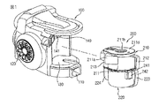
図2は、真空掃除機に適用される集塵装置装着部と集塵装置とを分離して示した斜視図であり、図3は、集塵装置の断面斜視図であり、図4は、図3のA部分の拡大図であり、図5は、集塵装置に捕集された塵埃の圧縮のために提供される駆動装置と集塵装置との結合関係を示す斜視図である。
Below, with reference to FIGS. 2-5, the vacuum cleaner provided with the dust collector which concerns on this invention with which the dust collection capacity became the maximum is demonstrated.
2 is a perspective view showing a dust collector mounting portion and a dust collector applied to a vacuum cleaner separately, FIG. 3 is a cross-sectional perspective view of the dust collector, and FIG. FIG. 5 is an enlarged view of a portion A in FIG. 3, and FIG. 5 is a perspective view showing a coupling relationship between the driving device and the dust collecting device provided for compressing the dust collected by the dust collecting device.
図2〜図5に示すように、本発明に係る集塵装置200は、掃除機本体100の前方部に着脱可能に装着される。
そして、掃除機本体100には、集塵装置200が装着されるための集塵装置装着部130が提供される。
2-5, the
The
そして、集塵装置200には、集塵容器220に捕集される塵埃の体積を減少させて、塵埃の集塵容量を増加させる一対の加圧部材310、320が備えられる。
ここで、一対の加圧部材310、320は、互いの相互作用により塵埃を圧縮して塵埃の体積を減少させ、これにより、集塵容器220の内部に捕集される塵埃の密度を増加させることによって、集塵容器220の最大集塵容量が増加するようにする。
The
Here, the pair of
以下では、説明の便宜のために、一対の加圧部材310、320のうちの何れか1つを第1加圧部材310とし、残りの1つを第2加圧部材320とする。
本実施の形態において、一対の加圧部材310、320のうち、少なくとも何れか1つは、集塵容器220の内部に移動可能に備えられて、一対の加圧部材310、320間で塵埃の圧縮作用を行う。
Hereinafter, for convenience of explanation, one of the pair of
In the present embodiment, at least one of the pair of pressurizing
すなわち、第1加圧部材310と第2加圧部材320が集塵容器220の内部に回転可能に備えられる場合、第1加圧部材310と第2加圧部材320が互いに向かって回転移動しながら、第1加圧部材310の一側面と第1加圧部材310の一側面に対向する第2加圧部材320の一側面との間の間隔が狭くなり、これにより、第1加圧部材310及び第2加圧部材320の間に位置する塵埃が圧縮される。
That is, when the
但し、本実施の形態においては、第1加圧部材310が集塵容器220の内部に回転可能に提供され、第2加圧部材320は、集塵容器220の内部に固定される。
したがって、第1加圧部材310は、回転部材となり、第2加圧部材320は、固定部材となる。
However, in the present embodiment, the
Therefore, the
一方、集塵容器220の内部には、塵埃が捕集される空間を形成する塵埃捕集部221が形成される。そして、塵埃捕集部221は、第1加圧部材310の自由端311が回転しながら描く仮想の軌跡を取り囲むように形成される。
詳細には、第2加圧部材320は、塵埃捕集部221の内周面と第1加圧部材310の回転中心をなす回転軸312の軸線間に提供されることが好ましい。
On the other hand, a
Specifically, the
すなわち、第2加圧部材320は、回転軸312の軸線と塵埃捕集部221の内周面をつなぐ面上に備えられる。このとき、第2加圧部材320は、塵埃捕集部221の内周面と回転軸312の軸線間の空間を完全にまたは一定部分遮蔽して、第1加圧部材310により塵埃が押し寄せれば、第1加圧部材310との相互作用によって塵埃を圧縮させる。
That is, the
このために、第2加圧部材320の一端321が塵埃捕集部221の内周面に一体に形成され、他端は、第1加圧部材310の回転軸312と同軸上に備えられる固定軸322に一体に形成されることが好ましい。
もちろん、第2加圧部材320の一端のみが塵埃捕集部221の内周面に一体に形成されるか、他端のみが固定軸322に一体に形成されることができる。言い換えれば、第2加圧部材320は、塵埃捕集部221の内周面と固定軸322のうち、少なくとも何れか一側に固定される。
For this purpose, one
Of course, only one end of the
しかし、第2加圧部材320の一端が塵埃捕集部221の内周面に一体に形成されなくても、第2加圧部材320の一端が塵埃捕集部221の内周面に隣接することが好ましい。
However, even if one end of the
そして、第2加圧部材320の他端が固定軸322に一体に連結されなくても、第2加圧部材320の他端は、固定軸322に隣接することが好ましい。
その理由は、第1加圧部材310により押し寄せる塵埃が、第2加圧部材320の側方に形成された隙間を介して漏れることを最小化するためである。
Even if the other end of the
The reason is to minimize the dust that is pressed by the
上記のように構成される第1加圧部材310と第2加圧部材320は、四角形状のプレートで構成されることが好ましい。そして、第1加圧部材310の回転軸312は、塵埃捕集部221の中心をなす軸線と同軸上に備えられることが好ましい。
The
一方、固定軸322は、塵埃捕集部221の一端から内側へ突出成形され、固定軸322の内部には、回転軸312の組立のために、軸方向に貫通される中空が形成される。そして、回転軸312の所定部分は、固定軸322の上側から中空に挿入される。
On the other hand, the fixed
上記の構成に加えて、本発明に係る真空掃除機は、第1加圧部材310の回転軸312に連結されて、第1加圧部材310を回転させる駆動装置400がさらに備えられる。
以下では、図4及び図5を参照して、集塵装置200と駆動装置400との結合関係について詳細に説明する。
In addition to the above configuration, the vacuum cleaner according to the present invention further includes a
Below, with reference to FIG.4 and FIG.5, the coupling | bonding relationship of the
駆動装置400は、駆動力を発生させる駆動モータ430と、駆動モータ430の駆動力を第1加圧部材310に伝達して、第1加圧部材310が回転されるようにする動力伝達部410、420が備えられる。
詳細には、動力伝達部410、420は、第1加圧部材310の回転軸312に結合される従動ギア410と、従動ギア410に動力を伝達する駆動ギア420が含まれる。
The driving
Specifically, the
そして、駆動ギア420は、駆動モータ430の回転軸に結合されて、駆動モータ430により回転される。
したがって、駆動モータ430が回転されると、駆動モータ430と結合された駆動ギア420が回転され、駆動ギア420によって駆動モータ430の回転力が従動ギア410に伝達されて、従動ギア410が回転するようになり、最終的に従動ギア410の回転によって第1加圧部材310が回転するようになる。
The
Accordingly, when the
ここで、駆動モータ430は、集塵装置装着部130の下側に備えられ、駆動ギア420は、駆動モータ430の回転軸に結合されて、集塵装置装着部130の底面に備えられる。
そして、駆動ギア420の外周面の一部は、集塵装置装着部130の底から外部に露出する。
Here, the
A part of the outer peripheral surface of the
このために、集塵装置装着部130の底面の下側には、駆動モータが設置されるモータ収容部(図示せず)が形成されることが好ましく、集塵装置装着部130の底面には、駆動ギア420の外周面の一部を外部に露出させるための開口部131が形成される。
For this reason, it is preferable that a motor housing (not shown) in which a drive motor is installed is formed below the bottom surface of the dust
一方、第1加圧部材310の回転軸312は、固定軸322の上側から固定軸322の中空に挿入され、従動ギア410は、集塵容器220の下側から固定軸322の中空に挿入されて、回転軸312と結合される。
そして、回転軸312は、固定軸322の上段により支持される段差部312cが形成され、段差部312cを基準に第1加圧部材310が結合される上部軸312aと従動ギア410が結合される下部軸312bとに分けられる。
On the other hand, the
The
ここで、下部軸312bと従動ギア410とが結合され得るように、下部軸312bには、従動ギア410のギア軸が挿入される溝312dが形成される。
Here, a
ここで、溝312dは、円状、四角形などの多様な形状に形成されることができ、従動ギア410のギア軸は、溝312dと対応する形状に形成される。
したがって、上記のように、回転軸312に従動ギア410が結合されると、従動ギア410が集塵容器220の外部に露出する。
このように従動ギア410が集塵容器220の外部に露出するに伴い、集塵装置装着部130に集塵装置200が装着されると、従動ギア410が駆動ギア420と噛み合うようになる。
Here, the
Therefore, as described above, when the driven
As the driven
一方、駆動モータ430は、正回転と逆回転が可能なモータであることが好ましい。言い換えれば、駆動モータ430は、両方向回転が可能なモータが用いられることができる。
このように、駆動モータ430の正逆回転を可能にするため、駆動モータ430は、シンクロナスモータ(synchronous motor)が用いられることができる。
On the other hand, the
As described above, a synchronous motor may be used as the
このような、シンクロナスモータは、モータ自体により正逆回転できるように構成され、モータの一方向の回転の際、モータに加えられる力が設定値以上になると、モータの回転が他方向に変換される。
このとき、モータに加えられる力は、第1加圧部材310が塵埃を加圧することによって発生する抵抗力(トルク)であって、抵抗力が設定された値に到達すると、モータの回転方向が変換されるように構成される。
シンクロナスモータは、モータ技術分野において周知のものであるため、これに対する詳細な説明は省略する。但し、シンクロナスモータによって駆動モータ430の正逆回転を可能にしたことが、本発明の技術的思想の一つである。
Such a synchronous motor is configured to be able to rotate forward and backward by the motor itself. When the motor is rotated in one direction, if the force applied to the motor exceeds a set value, the rotation of the motor is converted to the other direction. Is done.
At this time, the force applied to the motor is a resistance force (torque) generated when the
Since the synchronous motor is well known in the motor technical field, a detailed description thereof will be omitted. However, it is one of the technical ideas of the present invention that the forward and reverse rotation of the
そして、第1加圧部材310が回転して塵埃を圧縮させながら、もうこれ以上回転できない頂点に到達した場合にも、第1加圧部材310は塵埃を一定時間の間、加圧し続けるようにすることが好ましい。
ここで、第1加圧部材310が回転できない頂点とは、抵抗力が設定値に到達した場合を意味する。
The
Here, the apex at which the
そして、抵抗力が設定された値に到達すると、第1加圧部材310を回転させる動力、すなわち、駆動モータ430に印加される電源を一定時間の間、遮断して、第1加圧部材310が停止した状態で塵埃を圧縮した状態を維持するようにし、一定時間が過ぎると、再び駆動モータ430に電源を印加して、第1加圧部材310が移動され得るようにする。
このとき、駆動モータ430に印加される電源の遮断時点は、抵抗力が設定値に到達した場合であるから、駆動モータ430が再び駆動されると、駆動モータ430の回転方向は、電源遮断前と反対方向になるであろう。
When the resistance reaches a set value, the power for rotating the
At this time, the power supply applied to the
一方、第1加圧部材310は、集塵容器220に捕集された塵埃の除塵が容易になるように、圧縮された塵埃から離隔されることが好ましい。
このとき、第1加圧部材310は、第2加圧部材320と略180度の角度をなすように離隔して構成されることができる。ここで、第1加圧部材310の圧縮された塵埃からの離隔は、駆動モータ430によりなされることはもちろんである。
Meanwhile, the
At this time, the
これにより、塵埃捕集部221の内部に圧縮された塵埃が、塵埃捕集部221の内周面と第2加圧部材320のみに接触されるので、集塵容器220の塵埃の除塵が容易に行われることができる。
また、集塵容器220の内部に所定量以上の塵埃が集塵されると、集塵性能の低下とモータの過負荷などを防止するために、集塵容器220の除塵時期をユーザに表示することが好ましい。
As a result, the dust compressed in the
Further, when dust of a predetermined amount or more is collected in the
このために、掃除機本体100や集塵装置200またはハンドル(図示せず)に通知部(図示せず)が備えられるようにして、集塵容器220の内部に所定量以上の塵埃が集塵されて、第1加圧部材310の回転範囲が所定角度以下になると、集塵容器220の除塵時期をユーザに表示する。
For this purpose, a cleaner (not shown) is provided in the vacuum cleaner
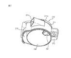
図6は、集塵装置の塵埃分離部と集塵容器とを分離して示した斜視図であり、図7は、図6に示す塵埃分離部の下部斜視図である。
図6及び図7に示すように、塵埃分離部210は、集塵容器220の上部に結合されて、塵埃分離部210から塵埃が分離された空気が下側へ移動されて、集塵容器220の内部に捕集される。
FIG. 6 is a perspective view showing the dust separation unit and the dust collection container of the dust collector separately, and FIG. 7 is a lower perspective view of the dust separation unit shown in FIG.
As shown in FIGS. 6 and 7, the
詳細には、塵埃分離部210の上部の外周面には、塵埃を含む空気が吸入される吸入口211aが塵埃分離部210の接線方向に形成され、塵埃分離部210の上側には、カバー221dが着脱可能に備えられる。
そして、カバー211dの中央部には、塵埃分離部210の内部、すなわちサイクロン部211によって塵埃が分離された空気が排出される排出口211bが形成される。
そして、排出口211bには、中空状の排気部材211cが結合され、排気部材211cの外周面には、サイクロン部211から塵埃分離過程を経た空気が排出される複数の通孔が形成される。
Specifically, a
A
A hollow exhaust member 211c is coupled to the
そして、塵埃分離部210の下側には、水平方向に区画板230が形成される。このような区画板230は、塵埃分離部210と集塵容器220とを区画する役割を果たす。また、区画板230は、塵埃分離部210が集塵容器220に結合された状態で、集塵容器220の内部に捕集された塵埃が塵埃分離部210側に飛散されるのを防止する役割をさらに行う。
A
そして、区画板230には、サイクロン部211から分離された塵埃を集塵容器220に排出させる塵埃排出口231が形成される。
このとき、塵埃排出口231は、第2加圧部材320の反対側に形成されることが好ましい。
The
At this time, the
その理由は、第2加圧部材320の両側に圧縮される塵埃の量を最大化して、塵埃の集塵容量を最大化するとともに、集塵容器220の内部に塵埃が捕集される過程で塵埃の飛散を最小化するためである。
塵埃分離部210と集塵容器220との結合のために、塵埃分離部210と集塵容器220には、それぞれ上部取っ手212と下部取っ手223が備えられる。
The reason is that the amount of dust compressed on both sides of the
In order to couple the
そして、集塵容器220が塵埃分離部210に装着された状態で、集塵容器220と塵埃分離部210とが結合され得るように、集塵装置200にはフック装置が備えられる。
詳細には、塵埃分離部210の外周面の下段には、フック係止部241が備えられ、集塵容器220の外周面の上段には、フック係止部241に選択的に結合されるフック部242が備えられる。
The
Specifically, a
一方、上述のサイクロン部211を主サイクロン部とし、塵埃捕集部221を主捕集部とするとき、本発明に係る集塵装置200は、掃除機の本体に備えられる少なくとも1つの補助サイクロン部140と集塵装置200に備えられる補助捕集部224をさらに備えて構成されることができる。
ここで、補助サイクロン部140は、主サイクロン部211から排出される空気に含まれた塵埃を二次的に分離する機能を果たし、補助捕集部224は、補助サイクロン部140から分離される塵埃を捕集する機能を果たす。
On the other hand, when the above-described
Here, the
そして、補助捕集部224は、上段が開口した状態で集塵装置200の外周面に備えられる。
本実施の形態において、補助捕集部224は、集塵容器220の外周面に備えられ、塵埃分離部210の外周面には、補助捕集部224と連通する補助塵埃流入部213が提供される。
And the
In the present embodiment, the
ここで、補助塵埃流入部213の外壁には、補助サイクロン部140の塵埃排出口141に選択的に連結される補助塵埃流入口213aが形成され、補助塵埃流入部213の底面は開放されて、補助捕集部224の上段と連通される。
これにより、主サイクロン部211が掃除機本体100に装着されると、補助塵埃流入ホール213aは補助サイクロン部140の塵埃排出口141と連結される。
したがって、補助サイクロン部140から分離される塵埃は、補助塵埃流入口213aを介して流入して、補助捕集部224に捕集される。
Here, an
Accordingly, when the
Therefore, the dust separated from the
以下では、上記の構成を有する本発明に係る真空掃除機の作用を説明する。
まず、真空掃除機に電源が供給されると、吸入モータによって吸入力が発生し、このような空気吸入力によって吸入ノズルに塵埃が含まれた空気が吸入される。
そして、吸入ノズルに吸入された空気は、本体吸入部110を経て主サイクロン部211の吸入口211aに流入される。そして、主サイクロン部211の吸入口211aを介して流入した空気は、主サイクロン部211の内壁に接線方向に案内されて、螺旋流を形成するようになり、これにより、空気に含まれた塵埃は、空気との遠心力の差により分離されて下降する。
Below, the effect | action of the vacuum cleaner which concerns on this invention which has said structure is demonstrated.
First, when power is supplied to the vacuum cleaner, suction input is generated by the suction motor, and air containing dust is sucked into the suction nozzle by such air suction input.
The air sucked into the suction nozzle flows into the
上記のように、主サイクロン部211の内壁に沿って螺旋流動をしながら下降する塵埃は、区画板230の塵埃排出口231を通過して、主捕集部221に捕集される。
そして、主サイクロン部211により一次的に塵埃が分離された空気は、排気部材211cを経て排出口211bを介して排出された後、補助サイクロン部に流入する。これにより、補助サイクロン部140の内部からサイクロン原理により分離された塵埃は、補助捕集部224に捕集され、補助サイクロン部140から分離された空気は、補助サイクロン部140から排出された後、掃除機本体100に流入して、本体排出部120を介して掃除機本体100から排出される。
As described above, the dust that descends while spirally flowing along the inner wall of the
The air from which the dust is primarily separated by the
一方、掃除過程で主捕集部221には、真空掃除機の内部に流入する塵埃のほとんどが捕集され、主捕集部221の内部の塵埃は、第1加圧部材310と第2加圧部材320により圧縮されて体積が最小になるので、主捕集部221の内部に多量の塵埃が捕集されるようになる。
On the other hand, most of the dust flowing into the vacuum cleaner is collected in the
このような掃除過程で集塵容器220の内部に一定量以上の塵埃が捕集されると、通知部で信号が発生し、信号によりユーザは集塵容器220の除塵時期が分かる。
そして、ユーザは、集塵装置200を掃除機本体100から分離し、集塵容器220の内部の塵埃を除塵する。
When a certain amount or more of dust is collected in the
Then, the user separates the
以下では、図8〜図13を参照して、掃除過程で集塵容器220の内部に捕集された塵埃の圧縮過程について詳細に説明する。
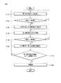
図8は、集塵装置の内部の塵埃圧縮過程を示すフローチャートであり、図9〜図13は、集塵装置の内部の塵埃圧縮過程を示す集塵容器の平面図である。
Hereinafter, the compression process of the dust collected in the
FIG. 8 is a flowchart showing the dust compression process inside the dust collector, and FIGS. 9 to 13 are plan views of the dust container showing the dust compression process inside the dust collector.
まず、掃除が行われると、サイクロン部211から分離された塵埃は、塵埃捕集部221に捕集される。このように塵埃が捕集される過程で一対の加圧部材310、320は、塵埃捕集部221に捕集された塵埃を圧縮させる。
詳細には、駆動モータ430が一方向に回転されると、駆動モータ430の回転動力が駆動ギア420を介して従動ギア410に伝達されて、従動ギア410が回転される。そして、従動ギア410の回転によって、回転軸312及び第1加圧部材310が一方向に回転される(S110)。
First, when cleaning is performed, the dust separated from the
Specifically, when the
このとき、駆動ギア420と従動ギア410とは互いに噛み合っているので、駆動モータ430が一方向に回転されると、駆動ギア420は、駆動モータ430と同じ方向に回転され、従動ギア410は、駆動モータ430の回転方向と反対方向である他方向に回転される。すなわち、従動ギア410及び第1加圧部材310の回転方向は、駆動モータ430の回転方向と反対方向になることが分かる。
At this time, since the
上記のように、第1加圧部材310が一方向(図9では半時計方向)に回転されると、第1加圧部材310は、第1加圧部材310と第2加圧部材320との間の塵埃を第2加圧部材320の一側面側に押し出して、塵埃を圧縮させる。このような、第1加圧部材310の回転は、塵埃を加圧する過程で発生する抵抗力が設定値に到達するまで持続する。
As described above, when the
抵抗力と設定値とを比較するステップが行われて(S120)、抵抗力が設定値以上になったと判断されると、駆動モータ430に印加される電源が遮断されて、第1加圧部材310が塵埃を圧縮する状態で停止する(S130)。
すると、第1加圧部材310は、停止した位置で一定時間の間、塵埃を加圧する。そして、一定時間が経過すると、再度駆動モータ430が駆動されて、第1加圧部材310が他方向に回転される(S140)。
A step of comparing the resistance force and the set value is performed (S120), and if it is determined that the resistance force is equal to or greater than the set value, the power applied to the
Then, the
ここで、第1加圧部材310は、抵抗力が設定された値に到達された状態で停止したので、その回転方向が変換して、図10のように時計方向に回転される。
そして、第1加圧部材310が時計方向に回転されると、第1加圧部材310は、第1加圧部材310と第2加圧部材320との間の塵埃を第2加圧部材320の他側面側に押し出して、塵埃を圧縮させる。
Here, since the first pressing
When the
このように、第1加圧部材310の回転中には、第1加圧部材310に加えられる抵抗力が設定値に到達されたか否かが判断される(S150)。
そして、抵抗力が設定値以上であると判断されると、駆動モータ430に印加される電源が遮断されて、第1加圧部材310が塵埃を圧縮した状態で停止する(S160)。
Thus, during the rotation of the
If it is determined that the resistance force is equal to or greater than the set value, the power applied to the
すると、第1加圧部材310は、停止した位置で一定時間の間、塵埃を加圧する。そして、一定時間が経過すると、再度駆動モータ430が駆動されて、第1加圧部材310が再度反対方向に回転される。
このように、圧縮作用は、図9〜図13に示すように、真空掃除機の作動中に継続的に繰り返される。
Then, the
Thus, the compression action is continuously repeated during operation of the vacuum cleaner, as shown in FIGS.
そして、このように圧縮作用が行われる中で、第1加圧部材310の回転範囲(θ)が設定された基準値(θp)以下になったか否かが判断される(S170)。
そして、第1加圧部材310の回転範囲(θ)が基準値(θp)以下になる場合、塵埃の除塵時期が外部に通知される(S180)。
そして、ユーザによって掃除機の作動が停止すれば、塵埃圧縮過程が終了する。
Then, it is determined whether or not the rotation range (θ) of the
When the rotation range (θ) of the
And if the operation | movement of a cleaner stops by a user, a dust compression process will be complete | finished.
図14は、集塵装置の内部の塵埃圧縮過程のうち、吸入モータの作動が中止された場合の加圧部材の制御方法を示すフローチャートである。
図14に示すように、ユーザの操作により掃除が行われると、空気中から塵埃が分離されて、塵埃捕集部221に捕集される。そして、一対の加圧部材310、320によって塵埃捕集部221に捕集された塵埃が圧縮される過程が行われる(S100)。ここで、塵埃圧縮過程は上述のおりであるので、詳細な説明は省略する。
FIG. 14 is a flowchart showing a method of controlling the pressure member when the operation of the suction motor is stopped during the dust compression process inside the dust collector.
As shown in FIG. 14, when cleaning is performed by a user operation, dust is separated from the air and collected in the
上記のように、塵埃の圧縮が行われる中で、ユーザの操作によって真空掃除機の作動が停止したか否かが判断される(S200)。そして、吸入モータの作動が停止すれば、移動中であった第1加圧部材310が、第2加圧部材320の一側へ移動される(S210)。
詳細には、第1加圧部材310は、移動していた方向と同じ方向である第2加圧部材320側に移動し続け、このように第1加圧部材310が移動する過程で、第1加圧部材310に作用する抵抗力が設定値以上になったか否かが判断される(S220)。そして、第1加圧部材に作用する抵抗力が設定値以上であると、第1加圧部材310は停止する(S230)。
As described above, it is determined whether the operation of the vacuum cleaner is stopped by the user's operation while the dust is compressed (S200). If the operation of the suction motor stops, the
Specifically, the
ここで、第1加圧部材310の移動停止は、駆動モータ430に印加される電源が遮断されることにより行われることはもちろんである。
すなわち、第1加圧部材310が吸入モータの作動停止の際、直ちに停止せず、塵埃を加圧し続ける位置まで第2加圧部材320側に移動した後に停止する。
Here, it goes without saying that the movement of the
That is, when the operation of the suction motor is stopped, the first pressurizing
このように、第1加圧部材310が塵埃を加圧し続ける位置まで移動した後に停止することによって、真空掃除機が作動しない場合にも、第1加圧部材310と第2加圧部材320の圧縮作用が持続的に維持される。ここで、吸入モータの作動が停止することは、掃除機の掃除作用が停止することと理解することができる。
そして、このように吸入モータの作動停止時にも、一対の加圧部材310、320によって塵埃の圧縮作用が維持されることから、吸入モータの作動停止後、ユーザが集塵装置200の内部の塵埃を除塵するとき、塵埃が容易に排出される。
Thus, even if the vacuum cleaner does not operate by stopping after the
Since the dust compression action is maintained by the pair of
また、吸入モータの作動停止時にも、一対の加圧部材310、320によって塵埃の圧縮作用が維持されることから、塵埃を除塵しない場合には、次回の掃除を行うとき、第1加圧部材310の移動による圧縮作用が容易に行われるようになる。
Further, since the compression action of the dust is maintained by the pair of
上述のように、本実施の形態は、掃除機の作動中に一対の加圧部材310、320によって塵埃の圧縮作用が行われるようにし、吸入モータの作動が停止した場合にも、塵埃の圧縮作用が維持されるように構成されるが、これとは異なり、掃除機の作動中には、一対の加圧部材310、320の圧縮作用が行われず、吸入モータが停止した場合に圧縮作用が行われるようにすることができる。
As described above, in the present embodiment, the dust is compressed by the pair of
すなわち、掃除機が作動する場合には、回転可能な第1加圧部材310が停止した状態を維持し、掃除機が作動が停止すれば、第1加圧部材310が第2加圧部材320の一側へ移動された後に停止して、塵埃の圧縮作用が行われるように構成されることができる。このとき、塵埃の圧縮が円滑に行われるように、第1加圧部材310が第2加圧部材320の一側へ移動された後に第2加圧部材320の他側へ移動されてから停止するように構成されることができる。
That is, when the cleaner is operated, the rotatable
また、第1加圧部材310のように回転可能な加圧部材が複数備えられることができ、この場合、吸入モータの作動が停止すれば、回転可能な複数の加圧部材が第2加圧部材320の両側へ移動された後に停止して、第2加圧部材320の両側で塵埃の圧縮作用が行われるであろう。
In addition, a plurality of rotatable pressure members such as the
以上では、図面に示すように、本発明に係る真空掃除機の一実施の形態としてキャニスタ方式の真空掃除機を説明したが、本発明は、上述の実施の形態に限定されず、アップライト方式の掃除機やロボット掃除機にも適用できることは勿論である。 In the above, as shown in the drawings, the canister-type vacuum cleaner has been described as one embodiment of the vacuum cleaner according to the present invention. However, the present invention is not limited to the above-described embodiment, and the upright system. Of course, the present invention can also be applied to other vacuum cleaners and robot cleaners.
100 掃除機本体
110 本体吸入部
120 本体排出部
130 集塵装置装着部
200 集塵装置
210 塵埃分離部
211 サイクロン部
220 集塵容器
221 塵埃捕集部
310、320 加圧部材
312 回転軸
322 固定軸
410 従動ギア
420 駆動ギア
430 駆動モータ
DESCRIPTION OF
Claims (19)
吸入モータが作動して、前記集塵装置の内部に塵埃が捕集されるステップと、
少なくとも1つの移動可能な加圧部材によって、前記集塵装置の内部に捕集される塵埃の体積を減少させる圧縮ステップと、が含まれる真空掃除機の制御方法。 In a vacuum cleaner equipped with a dust collector that collects dust,
A step of operating a suction motor to collect dust in the dust collector;
A method for controlling a vacuum cleaner, comprising: a compression step of reducing a volume of dust collected inside the dust collector by at least one movable pressure member.
前記加圧部材が、前記集塵装置の内部に固定された固定部材の一側へ移動される請求項1に記載の真空掃除機の制御方法。 In the compression step,
The method of controlling a vacuum cleaner according to claim 1, wherein the pressurizing member is moved to one side of a fixed member fixed inside the dust collector.
一側へ移動された前記加圧部材が、前記固定部材の他側へ移動される請求項2に記載の真空掃除機の制御方法。 In the compression step,
The method of controlling a vacuum cleaner according to claim 2, wherein the pressure member moved to one side is moved to the other side of the fixing member.
前記加圧部材に作用する抵抗力が設定値以上に到達したか否かが判断される請求項2又は3に記載の真空掃除機の制御方法。 In the compression step,
The method for controlling a vacuum cleaner according to claim 2 or 3, wherein it is determined whether or not a resistance force acting on the pressure member has reached a set value or more.
前記加圧部材の移動範囲が設定値以下になるか否かが判断される請求項1に記載の真空掃除機の制御方法。 In the compression step,
The method for controlling a vacuum cleaner according to claim 1, wherein it is determined whether or not the moving range of the pressure member is equal to or less than a set value.
前記吸入モータの作動が停止するステップと、
前記集塵装置の内部に備えられた複数の加圧部材のうち、少なくとも1つの加圧部材が異なる加圧部材側に移動されて停止するステップと、が含まれる真空掃除機の制御方法。 In a vacuum cleaner provided with a dust collecting device for collecting dust in the air sucked by the operation of the suction motor,
Stopping the operation of the suction motor;
A method of controlling a vacuum cleaner, comprising: at least one pressure member among a plurality of pressure members provided in the dust collecting device is moved to a different pressure member side and stopped.
前記他の加圧部材は、前記集塵装置の内部に固定される固定部材である請求項11に記載の真空掃除機の制御方法。 The at least one pressure member is a rotating member;
The method of controlling a vacuum cleaner according to claim 11, wherein the other pressure member is a fixed member fixed inside the dust collector.
前記吸入モータの作動停止時、前記回転部材は、前記固定部材の一側へ移動される請求項12に記載の真空掃除機の制御方法。 One rotating member is provided,
The method of controlling a vacuum cleaner according to claim 12, wherein when the suction motor is stopped, the rotating member is moved to one side of the fixed member.
前記吸入モータの作動停止時、何れか1つの回転部材は、前記固定部材の一側へ移動された後に停止し、残りの回転部材は、前記固定部材の他側へ移動された後に停止する請求項12に記載の真空掃除機の制御方法。 A pair of the rotating members is provided,
When the operation of the suction motor is stopped, any one rotating member stops after being moved to one side of the fixing member, and the remaining rotating members are stopped after being moved to the other side of the fixing member. Item 13. A method for controlling a vacuum cleaner according to Item 12.
Applications Claiming Priority (2)
| Application Number | Priority Date | Filing Date | Title |
|---|---|---|---|
| KR1020060018120A KR100871485B1 (en) | 2006-02-24 | 2006-02-24 | Method For Operating Dust Compressing Type of Dust Collector |
| KR1020060045415A KR100895145B1 (en) | 2006-05-20 | 2006-05-20 | Control method of vaccum cleaner |
Publications (2)
| Publication Number | Publication Date |
|---|---|
| JP2007222613A true JP2007222613A (en) | 2007-09-06 |
| JP2007222613A5 JP2007222613A5 (en) | 2008-12-11 |
Family
ID=38006737
Family Applications (1)
| Application Number | Title | Priority Date | Filing Date |
|---|---|---|---|
| JP2007019770A Pending JP2007222613A (en) | 2006-02-24 | 2007-01-30 | Method of controlling vacuum cleaner |
Country Status (3)
| Country | Link |
|---|---|
| EP (1) | EP1825797B1 (en) |
| JP (1) | JP2007222613A (en) |
| AU (1) | AU2007200407B2 (en) |
Families Citing this family (6)
| Publication number | Priority date | Publication date | Assignee | Title |
|---|---|---|---|---|
| AU2007356554B2 (en) * | 2007-07-16 | 2010-12-09 | Lg Electronics Inc. | Vacuum cleaner |
| KR100941429B1 (en) * | 2008-02-19 | 2010-02-11 | 엘지전자 주식회사 | Vacuum cleaner |
| RU2447825C1 (en) * | 2008-07-08 | 2012-04-20 | ЭлДжи ЭЛЕКТРОНИКС ИНК. | Vacuum cleaner |
| WO2011025072A1 (en) | 2009-08-24 | 2011-03-03 | 엘지전자 주식회사 | Vacuum cleaner |
| ES2620448T3 (en) * | 2009-11-04 | 2017-06-28 | Lg Electronics Inc. | Vacuum cleaner |
| CN102100507A (en) * | 2009-12-18 | 2011-06-22 | 乐金电子(天津)电器有限公司 | Novel dust collector dust collection barrel with manual compression structure |
Citations (8)
| Publication number | Priority date | Publication date | Assignee | Title |
|---|---|---|---|---|
| JPS5351663A (en) * | 1976-10-20 | 1978-05-11 | Sanyo Electric Co Ltd | Vacuum cleaner |
| JPS5485560A (en) * | 1977-12-20 | 1979-07-07 | Tokyo Electric Co Ltd | Electric cleaner |
| JPS54114366U (en) * | 1978-01-31 | 1979-08-11 | ||
| JPS54114358U (en) * | 1978-01-31 | 1979-08-11 | ||
| JPS54114367U (en) * | 1978-01-31 | 1979-08-11 | ||
| JPS54119272U (en) * | 1978-02-10 | 1979-08-21 | ||
| JPS5574553U (en) * | 1978-11-20 | 1980-05-22 | ||
| JP2005034213A (en) * | 2003-07-16 | 2005-02-10 | Matsushita Electric Ind Co Ltd | Electric vacuum cleaner |
Family Cites Families (6)
| Publication number | Priority date | Publication date | Assignee | Title |
|---|---|---|---|---|
| JPS54161751A (en) * | 1978-06-09 | 1979-12-21 | Sanyo Electric Co Ltd | Electric vacuum cleaner |
| JP3004538B2 (en) * | 1994-06-17 | 2000-01-31 | シャープ株式会社 | Electric vacuum cleaner |
| JP2002360474A (en) * | 2001-06-05 | 2002-12-17 | Toshiba Tec Corp | Dust collecting device, and electric vacuum cleaner |
| JP3699679B2 (en) * | 2001-12-28 | 2005-09-28 | 松下電器産業株式会社 | Vacuum cleaner |
| JP3899458B2 (en) * | 2002-01-07 | 2007-03-28 | 三菱電機株式会社 | Electric vacuum cleaner |
| CN100512740C (en) * | 2004-04-07 | 2009-07-15 | 东芝泰格株式会社 | Vacuum cleaner |
-
2007
- 2007-01-30 EP EP20070101391 patent/EP1825797B1/en active Active
- 2007-01-30 JP JP2007019770A patent/JP2007222613A/en active Pending
- 2007-01-31 AU AU2007200407A patent/AU2007200407B2/en active Active
Patent Citations (8)
| Publication number | Priority date | Publication date | Assignee | Title |
|---|---|---|---|---|
| JPS5351663A (en) * | 1976-10-20 | 1978-05-11 | Sanyo Electric Co Ltd | Vacuum cleaner |
| JPS5485560A (en) * | 1977-12-20 | 1979-07-07 | Tokyo Electric Co Ltd | Electric cleaner |
| JPS54114366U (en) * | 1978-01-31 | 1979-08-11 | ||
| JPS54114358U (en) * | 1978-01-31 | 1979-08-11 | ||
| JPS54114367U (en) * | 1978-01-31 | 1979-08-11 | ||
| JPS54119272U (en) * | 1978-02-10 | 1979-08-21 | ||
| JPS5574553U (en) * | 1978-11-20 | 1980-05-22 | ||
| JP2005034213A (en) * | 2003-07-16 | 2005-02-10 | Matsushita Electric Ind Co Ltd | Electric vacuum cleaner |
Also Published As
| Publication number | Publication date |
|---|---|
| AU2007200407B2 (en) | 2009-06-18 |
| EP1825797A3 (en) | 2012-04-11 |
| EP1825797B1 (en) | 2013-10-23 |
| AU2007200407A1 (en) | 2007-09-13 |
| EP1825797A2 (en) | 2007-08-29 |
Similar Documents
| Publication | Publication Date | Title |
|---|---|---|
| JP4695102B2 (en) | Dust collector and vacuum cleaner | |
| JP4705052B2 (en) | Control method of vacuum cleaner | |
| EP1949842B1 (en) | Vacuum cleaner | |
| CA2617398C (en) | A vacuum cleaner | |
| EP3750461B1 (en) | Dust collecting apparatus for vacuum cleaner and vacuum cleaner including same | |
| KR100871485B1 (en) | Method For Operating Dust Compressing Type of Dust Collector | |
| KR100871487B1 (en) | Control method of vaccum cleaner | |
| JP2007307352A (en) | Vacuum cleaner | |
| JP2007222613A (en) | Method of controlling vacuum cleaner | |
| CN101023852A (en) | Dust collector and vacuum cleaner | |
| KR100906848B1 (en) | Vaccum cleaner | |
| KR100485712B1 (en) | Apparatus for attaching/disattaching contaminant collecting receptacle of cyclone-type vacuum cleaner and vacuum cleaner having the same | |
| JP4625039B2 (en) | Vacuum cleaner and control method thereof | |
| JP2010104502A (en) | Vacuum cleaner | |
| EP3005923B1 (en) | Dust collector for vacuum cleaner | |
| KR100895145B1 (en) | Control method of vaccum cleaner | |
| KR100992221B1 (en) | Vacuum cleaner | |
| JP5210758B2 (en) | Electric vacuum cleaner | |
| KR101093941B1 (en) | Vacuum cleaner | |
| JP2009226132A (en) | Vacuum cleaner | |
| JP2008272021A (en) | Dust collection device and vacuum cleaner | |
| KR102656583B1 (en) | Robot cleaner | |
| KR101136618B1 (en) | Control method of vacuum cleaner | |
| JP2004105538A (en) | Vacuum cleaner | |
| KR100833362B1 (en) | Control method of vaccum cleaner |
Legal Events
| Date | Code | Title | Description |
|---|---|---|---|
| A521 | Written amendment |
Free format text: JAPANESE INTERMEDIATE CODE: A523 Effective date: 20081028 |
|
| A131 | Notification of reasons for refusal |
Free format text: JAPANESE INTERMEDIATE CODE: A131 Effective date: 20090317 |
|
| A601 | Written request for extension of time |
Effective date: 20090616 Free format text: JAPANESE INTERMEDIATE CODE: A601 |
|
| A602 | Written permission of extension of time |
Free format text: JAPANESE INTERMEDIATE CODE: A602 Effective date: 20090619 |
|
| A521 | Written amendment |
Effective date: 20090805 Free format text: JAPANESE INTERMEDIATE CODE: A523 |
|
| A02 | Decision of refusal |
Effective date: 20091110 Free format text: JAPANESE INTERMEDIATE CODE: A02 |
|
| A521 | Written amendment |
Free format text: JAPANESE INTERMEDIATE CODE: A523 Effective date: 20100310 |
|
| A911 | Transfer of reconsideration by examiner before appeal (zenchi) |
Free format text: JAPANESE INTERMEDIATE CODE: A911 Effective date: 20100323 |
|
| A912 | Removal of reconsideration by examiner before appeal (zenchi) |
Free format text: JAPANESE INTERMEDIATE CODE: A912 Effective date: 20100514 |
|
| A521 | Written amendment |
Free format text: JAPANESE INTERMEDIATE CODE: A523 Effective date: 20110712 |