JP2007207357A - Optical information reproducing method and device - Google Patents
Optical information reproducing method and device Download PDFInfo
- Publication number
- JP2007207357A JP2007207357A JP2006025596A JP2006025596A JP2007207357A JP 2007207357 A JP2007207357 A JP 2007207357A JP 2006025596 A JP2006025596 A JP 2006025596A JP 2006025596 A JP2006025596 A JP 2006025596A JP 2007207357 A JP2007207357 A JP 2007207357A
- Authority
- JP
- Japan
- Prior art keywords
- value
- cell
- recorded
- information
- cells
- Prior art date
- Legal status (The legal status is an assumption and is not a legal conclusion. Google has not performed a legal analysis and makes no representation as to the accuracy of the status listed.)
- Withdrawn
Links
- 238000000034 method Methods 0.000 title claims abstract description 75
- 230000003287 optical effect Effects 0.000 title claims abstract description 58
- 238000012937 correction Methods 0.000 abstract description 36
- 230000000694 effects Effects 0.000 abstract description 2
- 230000003247 decreasing effect Effects 0.000 abstract 2
- 238000005070 sampling Methods 0.000 description 21
- 238000001514 detection method Methods 0.000 description 9
- 238000010586 diagram Methods 0.000 description 5
- 238000000926 separation method Methods 0.000 description 5
- 238000006243 chemical reaction Methods 0.000 description 4
- 239000004065 semiconductor Substances 0.000 description 3
- 238000012545 processing Methods 0.000 description 2
- 238000004088 simulation Methods 0.000 description 2
- 230000001360 synchronised effect Effects 0.000 description 2
- KTTCLOUATPWTNB-UHFFFAOYSA-N 2-[2-[4-(6,7-dimethoxy-3,4-dihydro-1h-isoquinolin-2-yl)butylcarbamoyl]-4-methylphenoxy]ethyl methanesulfonate Chemical compound C1C=2C=C(OC)C(OC)=CC=2CCN1CCCCNC(=O)C1=CC(C)=CC=C1OCCOS(C)(=O)=O KTTCLOUATPWTNB-UHFFFAOYSA-N 0.000 description 1
- 230000005374 Kerr effect Effects 0.000 description 1
- 230000006978 adaptation Effects 0.000 description 1
- 230000015572 biosynthetic process Effects 0.000 description 1
- 239000013078 crystal Substances 0.000 description 1
- 230000007423 decrease Effects 0.000 description 1
- 238000004049 embossing Methods 0.000 description 1
- 238000005516 engineering process Methods 0.000 description 1
- 230000006870 function Effects 0.000 description 1
- 230000005415 magnetization Effects 0.000 description 1
- 238000012544 monitoring process Methods 0.000 description 1
- 230000010363 phase shift Effects 0.000 description 1
- 230000010287 polarization Effects 0.000 description 1
- 238000012827 research and development Methods 0.000 description 1
Images


Classifications
-
- G—PHYSICS
- G11—INFORMATION STORAGE
- G11B—INFORMATION STORAGE BASED ON RELATIVE MOVEMENT BETWEEN RECORD CARRIER AND TRANSDUCER
- G11B20/00—Signal processing not specific to the method of recording or reproducing; Circuits therefor
- G11B20/10—Digital recording or reproducing
- G11B20/10009—Improvement or modification of read or write signals
- G11B20/10018—Improvement or modification of read or write signals analog processing for digital recording or reproduction
- G11B20/10027—Improvement or modification of read or write signals analog processing for digital recording or reproduction adjusting the signal strength during recording or reproduction, e.g. variable gain amplifiers
Abstract
Description
この発明は、光ディスク等の情報記録媒体に記録された多値情報を再生する光学的情報再生方法及び装置、特に、再生信号のレベル補正及びAGC(Automatic Gain Control:自動利得制御)を精度良く効率的に行う方法及び装置に関するものである。 The present invention relates to an optical information reproducing method and apparatus for reproducing multi-value information recorded on an information recording medium such as an optical disk, and in particular, to accurately and efficiently perform reproduction signal level correction and AGC (Automatic Gain Control). It is related with the method and apparatus performed automatically.
従来、光ディスクにおいては渦巻状又は同心円状のトラック上に2値のデジタルデータが記録されている。記録方法には、エンボス加工等による凹凸のピット(ROMディスク)や無機・有機記録膜への穴形成(追記型ディスク)・結晶状態の違い(相変化ディスク)・磁化方向の違い(光磁気ディスク)等がある。 Conventionally, binary digital data is recorded on a spiral or concentric track in an optical disc. The recording method includes uneven pits (ROM disk) by embossing, hole formation in inorganic and organic recording films (write-once disk), crystal state difference (phase change disk), magnetization direction difference (magneto-optical disk) ) Etc.
これらの記録データを再生する際には、トラック上にレーザビームを照射してその反射光の強度差や磁気カー効果による偏光方向の差等を検出し、再生RF信号を得る。そして、得られた再生RF信号から2値のデータを検出している。 When reproducing these recorded data, a track is irradiated with a laser beam to detect a difference in intensity of the reflected light, a difference in polarization direction due to the magnetic Kerr effect, and the like to obtain a reproduced RF signal. Then, binary data is detected from the obtained reproduction RF signal.
近年、これら光ディスクの記録容量の高密度化を図る研究開発が進められており、情報の記録再生に関する光スポットを微小化する技術の1つとして、同じ光スポットの大きさを用いてより効率のよい多値記録再生の技術が提案されている。 In recent years, research and development to increase the recording capacity of these optical discs has progressed, and as one of the technologies for minimizing the light spot related to information recording and reproduction, more efficient using the same light spot size. A good multilevel recording / reproducing technique has been proposed.
例えば、本願発明者等は、多値記録再生技術の方式を特開平5−128530号公報において提案している(特許文献1)。即ち、光学的情報記録媒体の情報トラック上に、情報ピットのトラック方向の幅と、その情報ピットの再生用光スポットに対するトラック方向のシフト量の組み合わせによって多値情報を記録する方法を提案している。また、同公報では、その多値記録した情報ピットを再生する際、予め学習しておいた検出信号と光スポットから得られた検出信号との相関より多値情報を再生する方法を提案している。 For example, the inventors of the present application have proposed a multilevel recording / reproducing technique in Japanese Patent Laid-Open No. 5-128530 (Patent Document 1). That is, a method for recording multilevel information on an information track of an optical information recording medium by combining the width of the information pit in the track direction and the shift amount in the track direction with respect to the reproduction light spot of the information pit is proposed. Yes. In addition, this publication proposes a method for reproducing multi-value information from the correlation between a detection signal learned in advance and a detection signal obtained from a light spot when reproducing the multi-value recorded information pit. Yes.
更に、情報ピットのトラック方向のシフト量によって多値情報を記録する記録方法(サイファー方式)も提案されている。 Furthermore, a recording method (cypher method) for recording multi-value information by the shift amount of the information pits in the track direction has been proposed.
ここで、情報ピットのトラック方向の幅を他段階に変えた8値記録の場合の再生方法を説明する。まず、8レベルの情報ピットは、情報記録媒体に記録する時に2値データから8レベルに変換された後に各セルに記録される。 Here, a reproducing method in the case of 8-level recording in which the width of the information pit in the track direction is changed to another stage will be described. First, 8-level information pits are recorded in each cell after being converted from binary data to 8 levels when recording on an information recording medium.
8値記録の場合、1つのセルが3ビットの2値データに対応していることになる。例えば、3ビットの情報に対して、図20に示すように(0,0,0)、は0レベル、(0,0,1)は1レベル、(0,1,0)は2レベル、(0,1,1)は3レベルに対応させている。また、(1,0,0)は4レベル、(1,0,1)は5レベル、(1,1,0)は6レベル、(1,1,1)は7レベルに対応させている。 In the case of 8-level recording, one cell corresponds to 3-bit binary data. For example, for 3-bit information, as shown in FIG. 20, (0, 0, 0) is 0 level, (0, 0, 1) is 1 level, (0, 1, 0) is 2 level, (0, 1, 1) corresponds to 3 levels. (1, 0, 0) corresponds to 4 levels, (1, 0, 1) corresponds to 5 levels, (1, 1, 0) corresponds to 6 levels, and (1, 1, 1) corresponds to 7 levels. .
更に、8レベルの情報ピットの選択は、例えば、図20に示すようにセルのトラック方向の幅を16等分し、レベル0を何も情報ピットを記録しない、レベル1を2/16セル分の幅、レベル2を4/16セル分の幅とする。また、レベル3を6/16セル分の幅、レベル4を8/16セル分の幅、レベル5を10/16セル分の幅、レベル6を12/16セル分の幅、レベル7を14/16セル分の幅とする。
Furthermore, the selection of information pits at 8 levels is performed, for example, by dividing the width of the cell in the track direction into 16 equal parts as shown in FIG. 20, and recording no information pits at
このように選択した情報ピットをランダムに記録し、その反射光量を光検出器で受光し、得られた多値情報ピットからの再生信号を、光スポットの中心が、セルのトラック方向の幅の中央に来た時のタイミングでサンプリングする。そうすると、各レベルに対する再生信号の振幅として図21のような分布が得られる。 The information pits thus selected are recorded randomly, the amount of reflected light is received by a photodetector, and the reproduction signal obtained from the multi-value information pits is obtained with the center of the light spot having a width in the cell track direction. Sampling is performed at the timing when it comes to the center. Then, the distribution as shown in FIG. 21 is obtained as the amplitude of the reproduction signal for each level.
図21では情報ピットが何も書かれていないレベル0が続く時の再生信号の振幅の大きさを『1』、レベル7の情報ピットが連続して記録されている時の再生信号の振幅の大きさを『0』として規格化している。
In FIG. 21, the amplitude of the reproduction signal when
各レベルに対応する再生信号の値が幅を持つのは、注目している情報ピットの前後に書かれている情報ピットからの影響(符号間干渉)を受けるからである。図21に示すように隣のレベルと再生信号の振幅分布が重なっていると、固定した閾値では分離検出できないことが分かる。 The value of the reproduction signal corresponding to each level has a width because it receives an influence (intersymbol interference) from information pits written before and after the information pit of interest. As shown in FIG. 21, it can be seen that separation detection cannot be performed with a fixed threshold if the adjacent level and the amplitude distribution of the reproduction signal overlap.
ISOM2003の発表の例には、これを解決するための方法が述べられている(非特許文献1)。即ち、注目している情報ピットの値と、その前後の情報ピットの値とが予め分かっているピット列からの再生信号を読み取り記憶しておき(学習)、実際の情報ピットからの再生信号と記録しておいた値とを比べて(相関をみる)、分離検出する方式が述べられている。 A method for solving this problem is described in an example of announcement of ISOM 2003 (Non-patent Document 1). That is, the reproduction signal from the pit train in which the value of the information pit of interest and the information pit values before and after the information pit are known is read and stored (learning), and the reproduction signal from the actual information pit A method of separating and detecting by comparing the recorded values (see the correlation) is described.
以上が従来の多値記録再生の例であるが、いずれの方法においても光ディスクにおいて各種光ディスク間の反射率の違いや、1つの光ディスク内における内周側と外周側での再生周波数特性の違い等、再生信号は種々の要因でレベル変動や振幅変動が発生する。更には、ドライブの機械的要因、光学的な要因の違いによって起こる影響があり、これらを取り除く必要がある。 The above is an example of conventional multi-level recording / reproduction. In either method, the difference in reflectance between various optical disks in an optical disk, the difference in reproduction frequency characteristics between the inner and outer circumferences in one optical disk, etc. The reproduction signal undergoes level fluctuations and amplitude fluctuations due to various factors. Furthermore, there are effects caused by differences in the mechanical and optical factors of the drive, and these must be removed.
多値情報を再生する上でのレベル変動や振幅変動を抑える方法として、一般的にはデータ領域とデータ領域の間に一定の周期で固定パターン領域を設けることでAGC(Automatic Gain Control:自動利得制御)やレベル補正を行っている。 As a method for suppressing level fluctuation and amplitude fluctuation in reproducing multi-value information, generally, an AGC (Automatic Gain Control) is provided by providing a fixed pattern area with a constant period between data areas. Control) and level correction.
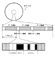
図22はその一般的なブロックの構成を簡易的に示す。図22に示すように光ディスクには多値情報の固定パターン領域とデータ領域が交互に記録されている。固定パターン領域は、バイアス、ゲイン、クロックマークから構成されている。 FIG. 22 simply shows the structure of the general block. As shown in FIG. 22, fixed pattern areas and data areas of multi-value information are recorded alternately on the optical disk. The fixed pattern area includes a bias, a gain, and a clock mark.
個々のマークの機能を説明すると、まず、バイアスマークはセルに最小マークを記録(或いは何も記録しない)して最小の信号レベルを検知し、これを基準レベルとしてデータ領域の再生信号のレベル補正を行うためのものである。 The function of each mark will be explained. First, the bias mark records the minimum mark in the cell (or records nothing), detects the minimum signal level, and uses this as a reference level to correct the level of the reproduction signal in the data area Is for doing.
ゲインマークはセルに最大マークを記録して最大信号レベルを検知し、データ領域の再生信号のAGCを行うためのものである。クロックマークはセルにゼロクロス検出できるようなトーン信号を記録して、多値データに同期したクロックとの位相ずれを検知することによってPLLを行うためのものである。 The gain mark is used to record the maximum mark in the cell, detect the maximum signal level, and perform AGC of the reproduction signal in the data area. The clock mark is used to perform PLL by recording a tone signal capable of detecting zero crossing in a cell and detecting a phase shift from a clock synchronized with multi-value data.
クロックマークによって、その後のデータ領域のサンプリングのタイミングを合わせることができる。また、固定パターン領域には、アドレス情報、波形等化適応情報等も含まれる場合があるが、図15では省略している。
更に高密度化を行おうとすると、光スポットに対してセルの大きさが益々小さくなり、レベル補正やAGCを行う上で新たな課題が生じる。つまり、隣接セルからの符号間干渉によって再生信号のSN比が減少し、低周波成分だけでなく、再生信号周波数帯域に近いノイズによってレベル変動や振幅変動の影響をより受けやすくなる。 If the density is further increased, the size of the cell becomes smaller with respect to the light spot, and a new problem arises in performing level correction and AGC. That is, the signal-to-noise ratio of the reproduction signal decreases due to intersymbol interference from adjacent cells, and it becomes more susceptible to level fluctuations and amplitude fluctuations due to noise close to the reproduction signal frequency band as well as low frequency components.
そのため、大幅に再生誤り率が上がってしまう。例えば、再生信号周波数が22MHzの多値情報データに対して、50kHz以下の低周波成分はハイパスフィルタ等によって除去可能であるが、実際には基板溝のウォブル成分や基板ノイズ等によって1MHz〜5MHz帯域でもノイズが生じる。これらは簡単に再生信号成分と分離することができない。 Therefore, the reproduction error rate is greatly increased. For example, low frequency components of 50 kHz or less can be removed by a high-pass filter or the like for multi-value information data with a reproduction signal frequency of 22 MHz. But noise occurs. These cannot be easily separated from the reproduction signal component.
その結果、再生信号レベルはノイズの影響を受けて誤った判定値を生じやすくなる。これらの問題は、固定パターン領域を増やしてレベル補正やAGCの頻度を多くすることで回避することもできるが、その分、データ領域が確保できなくなるため、フォーマット効率が低下するという問題があった。 As a result, the reproduction signal level is likely to generate an erroneous determination value due to the influence of noise. These problems can be avoided by increasing the fixed pattern area and increasing the frequency of level correction and AGC. However, since the data area cannot be secured, the format efficiency is lowered. .
本発明の目的は、フォーマット効率を低下させることなく、低周波成分だけでなく再生信号周波数帯域に近いノイズの影響も受けずに精度良く多値情報を判定することが可能な光学的情報再生方法及び装置を提供することにある。 An object of the present invention is to provide an optical information reproducing method capable of accurately determining multi-value information without lowering the format efficiency and not being affected by not only low frequency components but also noise close to the reproduction signal frequency band. And providing an apparatus.
本発明は、上記目的を達成するため、光学的情報媒体のトラック上に、仮想的に一定間隔のセルを設け、前記セルにおけるトラック方向の情報ピットの幅、面積、又は情報ピットの位相を変えることによって記録された多値情報を以下の方法で再生する。 In order to achieve the above object, according to the present invention, virtually constant-spaced cells are provided on a track of an optical information medium, and the width, area, or phase of the information pit in the track direction in the cell is changed. The multi-value information recorded by this is reproduced by the following method.
本発明の第1の方法は、N値(N≧3)で記録されている複数のセル毎に、M値(M<N)で記録されているセルを設け、光スポットの中心が、前記M値で記録されたセルの中央に来た時にサンプリングした再生信号のセル中央値と学習情報から得られる参照値との差分に基づいて、前記M値で記録されたセルに続くN値で記録されたセルの再生信号レベルを補正することを特徴とする。 In the first method of the present invention, a cell recorded with an M value (M <N) is provided for each of a plurality of cells recorded with an N value (N ≧ 3), and the center of the light spot is Based on the difference between the cell median value of the reproduction signal sampled when it comes to the center of the cell recorded with the M value and the reference value obtained from the learning information, the N value following the cell recorded with the M value is recorded. The reproduction signal level of the selected cell is corrected.
また、第2の方法は、N値(N≧3)で記録されている複数のセル毎に、M値(M<N)で記録されているセルを設け、光スポットの中心がM値で記録されたセルの中央に来た時にサンプリングした再生信号のピークを検出することによって、再生信号をAGCすることを特徴とする。 In the second method, a cell recorded with an M value (M <N) is provided for each of a plurality of cells recorded with an N value (N ≧ 3), and the center of the light spot is an M value. The reproduction signal is AGCed by detecting the peak of the reproduction signal sampled when it comes to the center of the recorded cell.
更に、第3の方法は、N値マーク(N≧3)で記録されている複数のセル毎に、連続したM値(M<N)で記録されているセルを設け、光スポットの中心が、前記M値で記録されたセルとそれに続くM値で記録されたセルとの境界に来た時にサンプリングした再生信号と学習情報から得られる参照値との差分に基づいて、それに続くN値で記録されたセルの再生信号のレベルを補正することを特徴とする。 Furthermore, the third method provides a cell recorded with a continuous M value (M <N) for each of a plurality of cells recorded with an N value mark (N ≧ 3), and the center of the light spot is Based on the difference between the playback signal sampled when the cell is recorded at the M value and the cell recorded at the subsequent M value and the reference value obtained from the learning information, the subsequent N value It is characterized in that the level of the reproduction signal of the recorded cell is corrected.
本発明によれば、データ領域の一部に多値度を落としたセルを設けることにより、記録媒体のフォーマット効率を低下させることなく、高密度記録された多値情報を精度良く再生できる。特に、低周波成分だけでなく、再生信号周波数帯域に近いノイズの影響も除いて精度良く多値情報を判定することができる。 According to the present invention, by providing a cell with a reduced multi-value level in a part of the data area, multi-value information recorded at high density can be accurately reproduced without reducing the format efficiency of the recording medium. In particular, not only the low frequency component but also the influence of noise close to the reproduction signal frequency band can be removed and the multi-value information can be determined with high accuracy.
次に、発明を実施するための最良の形態について図面を参照して詳細に説明する。図1は本発明に係る光学的情報記録再生装置の一実施形態の構成を示すブロック図である。図中1は螺旋状または同心円状のトラックが形成された情報記録媒体である光ディスク、2は光ディスク1を回転駆動するスピンドルモータ、3は光ディスク1に対して多値情報を記録し、或いは再生するための光ヘッドである。
Next, the best mode for carrying out the invention will be described in detail with reference to the drawings. FIG. 1 is a block diagram showing a configuration of an embodiment of an optical information recording / reproducing apparatus according to the present invention. In the figure,
光ヘッド3には図示しない半導体レーザや対物レンズ、光検出器等が設けられ、半導体レーザからのレーザ光を対物レンズで絞って微小光スポットとして光ディスク1上に照射する。その反射光は光ヘッド3内の光検出器で検出され、演算増幅回路4は光検出器からの信号に基づいて光スポットが所望のトラック上に沿って走査するように制御するためのフォーカスエラー信号/トラッキングエラー信号を生成する。
The
サーボ回路5は演算増幅回路4からの信号に基づいて光スポットが所望のトラック上に沿って走査するようにフォーカス制御/トラッキング制御を行う。また、サーボ回路5は光ディスク1が線速度一定或いは角速度一定等で回転するようにスピンドルモータ2の回転制御を行う。
The
多値情報を光ディスク1に記録する場合には、2値データ6の入力を、多値化回路7により多値データに変換し、変調回路8により多値データに応じた信号を出力する。そして、レーザ駆動回路9により光ヘッド3内の半導体レーザを駆動し、光ディスク1のトラック上に多値情報に応じたマークを記録することによって行う。
When multi-value information is recorded on the
多値情報を記録する方法としては、例えば、光ディスク1のトラック上に仮想的にセルを設け、そのセルにおけるトラック方向の情報ピットの幅、面積、或いは情報ピットの位相を変えることによって記録する方法がある。
As a method for recording multi-value information, for example, a cell is virtually provided on a track of the
一方、多値情報を再生する場合には、光ヘッド3により再生用の光スポットを光ディスク1上に照射し、光ディスク1からの反射光を光ヘッド3内の光検出器で検出する。演算増幅回路4はその検出信号を処理して再生信号を生成し、AD変換回路10によりその再生信号をデジタル信号に変換する。
On the other hand, when reproducing multi-value information, the
更に、AGC回路19により再生信号のゲインを調整し、セル中央値/ セル間値分離検出回路12によりセル中央値とセル間値に分離する。これらの処理はPLL回路11によって生成されたクロックにより行う。セル中央値/セル間値分離検出回路12で分離されたセル中央値はセル中央値用波形等化回路13により波形等化処理され、セル間値はセル間値用波形等化回路14により波形等化処理される。
Further, the gain of the reproduction signal is adjusted by the
そして、学習用メモリ17から学習テーブルデータの参照値を読み出し、この両者の値に基づいて多値データ判定回路15により多値レベルを判定する。ここで、本発明に係る補正回路18は、判定された多値情報と学習テーブルデータの参照値を用いて補正値を算出し、これを波形等化されたデータに加算することでレベル補正やAGCを行う。更に、多値−2値変換回路16により2値データに変換し、2値データ20として出力する。
Then, the reference value of the learning table data is read from the learning
以上が本発明による多値情報を記録再生する方法の概略である。ここで、補正回路18の説明を始める前に、上記セル間値とセル中央値のサンプリング位置の違いとそれぞれの特徴を図2、図3を用いて説明する。
The above is the outline of the method for recording and reproducing multi-value information according to the present invention. Here, before the description of the
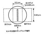
図2はセル中央値をサンプリングしている際の前後のセルと光スポットの位置関係を示す。一例として、光ディスク1のトラックピッチは0.32μm、光スポットの大きさは0.405μm(波長405nm、対物レンズの開口数:NA0.85)、セルの大きさは0.2μmとする。
FIG. 2 shows the positional relationship between the front and rear cells and the light spot when sampling the cell median value. As an example, the track pitch of the
このパラメータにおいて注目セルのセル中央値は、先行セルと後行セルのレベルが0〜7に変化することで、同じ値を取らず、符号間干渉の影響で幅を持つことが実験的に分かっている。これは、図2で真中のセル上にある光スポットの裾が左右のセル上にかかっていることからも直感的に分かる。このセル中央値に対する符号間干渉の影響は、光スポットの大きさに対してセルが小さくなるほど大きくなっていく。 It is experimentally found that the cell median value of the target cell in this parameter does not take the same value and has a width due to the influence of intersymbol interference when the levels of the preceding cell and the succeeding cell change from 0 to 7. ing. This is intuitively understood from the fact that the bottom of the light spot on the middle cell in FIG. The influence of the intersymbol interference on the cell median value increases as the cell becomes smaller with respect to the size of the light spot.
図3はセル間値をサンプリングする際の左右のセルの境界に光スポットが来た時の位置関係を示すものである。光スポットの大きさ0.405μmに対して、2つ分のセルの幅は0.4μmであり、光スポットのほとんどが左右のセル上にある。つまり、左右のセルの境界でサンプリングされたセル間値はその外側からの影響がほとんど無く、左右のセルより外側からの符号間干渉の影響が小さいものとなる。 FIG. 3 shows the positional relationship when the light spot comes to the boundary between the left and right cells when sampling the value between cells. The width of two cells is 0.4 μm with respect to the light spot size of 0.405 μm, and most of the light spots are on the left and right cells. That is, the inter-cell values sampled at the boundary between the left and right cells have almost no influence from the outside, and the influence of intersymbol interference from the outside is smaller than that of the left and right cells.
以上のセル中央値とセル間値は、セル中央値/セル間値分離検出回路12においてPLL回路11で生成された多値データに同期したクロックでそれぞれサンプリングすることで得られる。セル中央値サンプリング用のクロックとセル間値サンプリング用のクロックは、同じ周波数であって、互いに1/2周期(1つのセルを1周期とする)位相が異なるものである。
The above-described cell median and inter-cell values are obtained by sampling each of the cell median / inter-cell value
更に、多値データ判定回路15における多値データ判定方法としては、例えば、本願発明者等が、先に、特願2005−047198号で提案している方法を用いることができる。この方法については、詳しく後述する。
Furthermore, as the multi-value data determination method in the multi-value
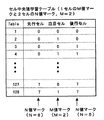
次に、本発明に係る補正回路18のレベル補正及びAGC回路19のAGCの方法について詳細に説明する。図4は1ブロックにM値マークとN値マークのセルを記録する構成とレベル補正に用いるデータのサンプリング場所を示しており、これを第1の方法とする。
Next, the level correction of the
ここで、M=2、N=8とし、1つのM値マークと3つのN値マークのセルを1ブロックとみなす。M値マークは2値で記録されているので、例えば、図5に示すように0レベルは記録せず、1レベルは最大幅になるようにトラック方向に記録する。これは、8値記録で置き換えて考えれば、0レベルと7レベルが記録、再生されることと同じになる。ここで、M値マークを2値で記録することによる利点が2つある。 Here, M = 2 and N = 8, and one M-value mark and three N-value mark cells are regarded as one block. Since the M value mark is recorded in binary, for example, as shown in FIG. 5, the 0 level is not recorded, and the 1 level is recorded in the track direction so that the maximum width is obtained. If this is replaced with 8-level recording, it is the same as recording and reproduction of the 0 level and the 7 level. Here, there are two advantages by recording the M-value mark in binary.
まず、M値マークの再生データはほとんどエラーを生じることがない。次に、M値マークのセル中央値の最大・最小レベルは再生信号の最大・最小レベルと同じになり、そのレベル差を一定のブロック数でモニタリングすることで再生信号の振幅変動を計測できる。本発明では、上述のようなエラーを生じることがないという前者を補正回路18におけるレベル補正に利用し、振幅変動を計測できるという後者をAGC回路19に利用する。
First, the reproduction data of the M value mark hardly causes an error. Next, the maximum / minimum level of the cell median value of the M value mark becomes the same as the maximum / minimum level of the reproduction signal, and the amplitude fluctuation of the reproduction signal can be measured by monitoring the level difference with a certain number of blocks. In the present invention, the former that the above-described error does not occur is used for level correction in the
補正回路18におけるレベル補正方法について説明する。図6は、例えば、図4の構成で記録された多値マークを再生し、その判定値に基づいて補正値を求めるアルゴリズムを示す。まず、ステップ1で1ブロック毎に補正動作を開始する。次に、ステップ2でサンプリングされたM値マークの再生信号、この場合はセル中央値が入力される。
A level correction method in the
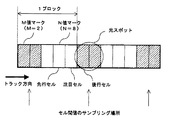
次に、ステップ3で学習用メモリ17の学習テーブルデータにアクセスする。そして、ステップ4で対象となるM値マークの注目セルと、その前後をN値マークのセルとした3つの連続するセル(先行セル、注目セル、後行セル)の多値判定値に基づいて、図7に示す全128(8×2×8)パターンの学習情報からセル中央値の参照値を求める。
Next, in
この128パターンの情報がパターン同士の符号間干渉を防ぐためにパターン毎に所定間隔を空けて、光ディスク1上のユーザデータ領域の先頭部分に記録されている。図示しない装置内の各部を制御するコントローラはユーザデータ領域の情報を再生する前に各パターンのセル中央値の再生信号を検出し、そのサンプリング値を学習用メモリ17に参照値として記憶させておく。
The 128 patterns of information are recorded at the beginning of the user data area on the
なお、上述したような学習情報ではなく、予めシミュレーションで求めた理想のサンプリング値自身をユーザデータ領域の先頭部分に記録しておくようにしてもよい。その後、ステップ5でM値マークのセルの再生信号とそれに対応する参照値の差分を計算し、この差分を補正値とする。更に、ステップ6で注目セルより後に続く3つのN値マークの再生信号にそれぞれ補正値を加算し、ステップ7にて終了する。
Note that instead of the learning information as described above, an ideal sampling value itself obtained in advance by simulation may be recorded in the head portion of the user data area. Thereafter, in
ここで、3つの連続するセルにおける多値判定値が誤ったものである場合には、算出される補正値は同様に信頼性の低い値となる。しかし、M値マークのセルは2値レベルであるのでその判定値はほぼ正解値をとり、その結果、前後セルの判定値の確度を上げることができる。これは、前後セルの判定値は判定アルゴリズムの過程でM値マークのセルの判定値を利用して決定するからである。従って、3つの連続するセルにおける多値判定値の確度を高められ、補正値の精度を向上することが可能となる。 Here, when the multi-level determination value in three consecutive cells is incorrect, the calculated correction value is similarly a low reliability value. However, since the cells of the M-value mark are at the binary level, the determination value takes almost the correct value, and as a result, the accuracy of the determination values of the preceding and subsequent cells can be increased. This is because the determination values of the preceding and following cells are determined using the determination value of the cell of the M value mark in the process of the determination algorithm. Therefore, the accuracy of the multi-level determination value in three consecutive cells can be increased, and the accuracy of the correction value can be improved.
次に、第2の方法について説明する。この場合は、M=2、N=8とし、1ブロックに2つのM値マークと3つのN値マークのセルが記録されているものとする。この構成を図8に示す。 Next, the second method will be described. In this case, it is assumed that M = 2 and N = 8, and two M-value marks and three N-value mark cells are recorded in one block. This configuration is shown in FIG.
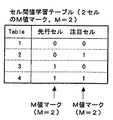
第1の方法と同様に図6のステップ1で1ブロック毎に補正動作を開始する。次に、ステップ2でM値マークの2つのセルの境界でサンプリングされた再生信号、この場合はセル間値が入力される。ステップ3で学習テーブルデータにアクセスし、ステップ4で対象となるM値マークの2つの連続するセル(先行セル、注目セル)の多値判定値に基づいて、図9に示す全4(2×2)パターンの学習情報からセル間値を参照値として求める。
As in the first method, the correction operation is started for each block in
この4パターンの情報も、同様に光ディスク1上のユーザデータ領域の先頭部分に記録されている。図示しないコントローラは同様にユーザデータ領域の情報を再生する前に各パターンのセル間値の再生信号を検出し、そのサンプリング値を学習用メモリ17に参照値として記憶させておく。
These four patterns of information are similarly recorded at the head portion of the user data area on the
その後、ステップ5でセル間値の再生信号とそれに対応する参照値の差分を計算し、この差分を補正値とする。そして、ステップ6で注目セルより後に続く3つのN値マークの再生信号にそれぞれ補正値を加算し、ステップ7にて終了する。
Thereafter, in
次に、第3の方法について説明する。この場合は、M=2、N=8とし、1ブロックに3つのM値マークと3つのN値マークのセルが記録されているものとする。この構成を図10に示す。 Next, the third method will be described. In this case, it is assumed that M = 2 and N = 8, and three M-value marks and three N-value mark cells are recorded in one block. This configuration is shown in FIG.
第1の方法と同様に図6のステップ1で1ブロック毎に補正動作を開始する。次に、ステップ2でサンプリングされた3つのM値マークの中心となるセルの再生信号、この場合はセル中央値が入力される。
As in the first method, the correction operation is started for each block in
次に、ステップ3で学習テーブルデータにアクセスし、ステップ4で対象となるM値マークの3つの連続するセル(先行セル、注目セル、後行セル)の多値判定値に基づいて、図11に示す全8(2×2×2)パターンの学習情報からセル中央値を参照値として求める。
Next, the learning table data is accessed in
この8パターンの情報も、同様に光ディスク1上のユーザデータ領域の先頭部分に記録されている。図示しないコントローラはユーザデータ領域の情報を再生する前に各パターンのセル中央値の再生信号を検出し、そのサンプリング値を学習用メモリ17に参照値として記憶させておく。
The eight patterns of information are also recorded at the head portion of the user data area on the
その後、ステップ5で3つのM値マークの中心となるセルの再生信号とそれに対応する参照値の差分を計算し、この差分を補正値とする。そして、ステップ6で注目セルより後に続く3つのN値マークの再生信号にそれぞれ補正値を加算し、ステップ7にて終了する。
Thereafter, in
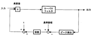
次に、AGC回路19の方法について説明する。本発明におけるAGCは、再生信号の最大・最小レベルを検知して振幅を調整する基本的な構成を備えており、その最大・最小レベルをどのマークを用いて検出するかという点に特徴がある。
Next, a method of the
即ち、従来の多値記録再生では情報データとは別の領域にある固定マークを記録して検出していたが、本発明では情報データとして多値度を落として記録された2値マークの信号レベルを用いて検出する。もちろん、N値マークの再生信号は多段階レベルであるのでAGCの入力信号としては用いることはできない。 That is, in the conventional multi-level recording / reproduction, a fixed mark in a different area from the information data is recorded and detected. However, in the present invention, the binary mark signal recorded with the multi-level reduced as the information data. Detect using level. Of course, the reproduction signal of the N value mark cannot be used as an input signal of AGC because it has a multilevel level.
図12はAGC回路19の一例を示す概略ブロック図である。入力された再生信号における2値マークに対して一定のブロック間でピーク検出を行い、最大・最小レベルを検知する。その後、最大・最小レベルの差と基準振幅値との差に係数を掛けてゲインを更新する。最大・最小レベルの差が基準振幅値と等しければ更新される値はゼロとなる。ゲインは、その後、1が加算され、入力信号に乗算することでAGCを行う。なお、AGCの入出力特性を決める回路上の素子構成等については特に限定するものではないので省略する。
FIG. 12 is a schematic block diagram showing an example of the
ここで、図4の例の場合には、光スポットの中心が、M値で記録されたセルの中央に来た時にサンプリングした再生信号のセル中央値をピーク検出することによって再生信号をAGCするものである。 In the case of the example of FIG. 4, the reproduction signal is AGCed by detecting the peak of the cell median value of the reproduction signal sampled when the center of the light spot comes to the center of the cell recorded with the M value. Is.
また、図8の例の場合には、光スポットの中心が、連続した2つのM値で記録された各セルの中央に来た時にサンプリングした再生信号のセル中央値をピーク検出することによって再生信号をAGCする。 In the case of the example of FIG. 8, reproduction is performed by detecting the peak of the cell median value of the reproduction signal sampled when the center of the light spot comes to the center of each cell recorded with two consecutive M values. AGC the signal.
更に、図10の例の場合には、光スポットの中心が、連続した3つのM値で記録された各セルの中央に来た時にサンプリングした再生信号のセル中央値をピーク検出することによって再生信号をAGCする。 Further, in the case of the example of FIG. 10, reproduction is performed by detecting the peak of the cell median value of the reproduction signal sampled when the center of the light spot comes to the center of each cell recorded with three consecutive M values. AGC the signal.
このように本発明に係るAGC回路は、M値マークとN値マークの構成を変えた第1、第2、第3の方法のいずれにおいても同様に適用でき、M値マークのセル中央値をサンプリングしてピーク検出するものである。以上が、本発明の多値情報を再生する方法である。 As described above, the AGC circuit according to the present invention can be similarly applied to any of the first, second, and third methods in which the configurations of the M value mark and the N value mark are changed, and the cell median value of the M value mark is determined. The peak is detected by sampling. The above is the method for reproducing multi-value information of the present invention.
次に、多値データ判定回路15の判定方法について図13〜図19を参照して説明する。これは、上述のように特願2005−047198号で提案している。本実施形態では、0〜7の8値の多値データを再生するものとする。図13は多値データ判定回路15における多値データの判定方法を説明する図である。多値データ判定回路15は、主にセル中央値判定部19、セル間値判定部20、最終値判定部21に別れている。
Next, a determination method of the multi-value
最初に、セル中央値判定部19について説明する。セル中央値判定部19は図2で説明したような3つの連続セル(先行セル、注目セル、後行セル)を考えて判定するものである。多値データ判定回路15はセル中央値の再生信号が入力されると、ステップ1で操作を開始する。
First, the cell median
次いで、ステップ2で、先行セルの値を決定する(これは、1ステップ前に求めた注目セルの値を選択する)。例えば、1ステップ前に判定した注目セルの値が『7』だった場合には、先行セルの値は『7』として選択する(ここで言う「選択」とは最終的な判定ではなく、仮決めを意味する)。或いは、先行セルの値を選択する方法として、セル中央値の再生信号(光スポットが先行セルの中央に位置する時のサンプリング値)を各レベルに応じた複数の閾値でレベルスライスして決定しても良い。
Next, in
次に、ステップ3で、後行セルの値をセル中央値の再生信号(光スポットが後行セルの中央に位置する時のサンプリング値)をレベルスライスして選択する(レベルスライスで最も近い値を選択)。例えば、後行セルの値が『7』として選択されたとする。ここまでで、3つの連続セルのうち先行セルと後行セルの値が選択されたことになる。
Next, in
次に、ステップ4で、先行セルと後行セルの値を用いてセル中央値学習テーブル(図14)からセル中央値の再生信号に最も近い注目セルの値を選択する。更に、ステップ5で2番目に近い値を選択する。また、ステップ6で、ステップ4及びステップ5で選択した値をそれぞれ第1候補『a』、第2候補『b』として決定する。
Next, in
このセル中央値判定部19におけるステップ4〜6について図14、図15を用いて更に詳細に説明する。図14は多値データの判定に用いる学習テーブルを示す。図14(a)はセル中央値学習テーブルであり、先行セル、注目セル、後行セルがとりうるすべての組合せ、全512パターン(8×8×8)のテーブルが作られている。512パターンの情報は光ディスク1上のユーザデータ領域の先頭部分に記録されており、ユーザデータ領域の情報を再生する前に各パターンの注目セルのセル中央値の再生信号を検出して、そのサンプリング値を学習用メモリ17に参照値として記憶させる。
次に、図15を用いて図13のセル中央値判定部19におけるステップ4〜6のセル中央値学習テーブルを用いた注目セルの候補値を決定する方法を説明する。まず、ステップ11で操作を開始する。ステップ12で、サンプリングされたセル中央値の再生信号は順次セル中央値判定部に入力されていく。また、ステップ13で学習用メモリ17にアクセスし、ステップ14でセル中央値が入力される毎に図14(a)のセル中央値学習テーブルで得られた参照値を学習用メモリ17から順次読み出す。
Next, a method for determining a candidate value of a target cell using the cell median value learning table in
ここで、読み出すテーブルは先行セルと後行セルの値が『7』として選択されたので(図13の説明を参照)、全512パターンから8パターン、即ち(7,0,7)〜(7,7,7)の組合せに絞られる。次に、ステップ15で、セル中央値と8パターンの参照値との差分の絶対値を計算し、これをM値とする。ステップ16では、8つのM値を比較して、注目セルの値が『a』の場合にそのM値(これをM(a)と表す)が最も小さくなるとして、『a』をセル中央値判定部19における第1候補値として決定する。
Here, since the value of the preceding cell and the succeeding cell is selected as “7” in the table to be read (see the description of FIG. 13), eight patterns out of all 512 patterns, that is, (7, 0, 7) to (7 , 7, 7). Next, in
更に、注目セルの値が『b』の場合にそのM値(これをM(b)と表す)が2番目に小さくなるとして、『b』をセル中央値判定部19における第2候補値として決定する。その後、ステップ17に進み、操作を終了する。以上がセル中央値判定部19の説明である。
Further, when the value of the cell of interest is “b”, the M value (represented as M (b)) is assumed to be the second smallest, and “b” is set as the second candidate value in the cell median
続いて、図13に戻ってセル間値判定部20における注目セルの値を決定する方法について図14、図16を用いて詳細に説明する。図13に示すようにセル間値判定部20は、ステップ7で、ステップ2で決定した先行セルの値を用いてセル間値学習テーブル(図14)からセル間値の再生信号に最も近い注目セルの値を選択する。更に、ステップ8で、ステップ7で選択した値を候補値『x』として決定する。
Next, returning to FIG. 13, a method for determining the value of the cell of interest in the inter-cell
セル間値判定部20におけるステップ7、8について図14、図15を用いて詳細に説明する。図14(b)はセル間値学習テーブルであり、先行セル、注目セルがとりうるすべての組合せ、全64パターン(8×8)のテーブルが作られている。64パターンの情報も同様に光ディスク1上のユーザデータ領域の先頭部分に記録されており、ユーザデータ領域の情報を再生する前に各パターンの注目セルのセル間値の再生信号を検出して、そのサンプリング値を学習用メモリ17に参照値として記憶させる。
次に、図16を用いて、図13のセル間値判定部20におけるステップ7、8のセル間値学習テーブルを用いた注目セルの候補値を決定する方法を説明する。まず、ステップ18で操作を開始する。また、ステップ19で、サンプリングされたセル間値の再生信号は順次セル間値判定部20に入力されていく。また、ステップ20で、学習用メモリ17にアクセスして、ステップ21で、セル間値が入力される毎に図14(b)のセル間値学習テーブルで得られた参照値を学習用メモリ17から順次読み出す。
Next, a method for determining a candidate cell candidate value using the inter-cell value learning table in
ここで、読み出すテーブルは先行セルの値が『7』として選択されたので(図13の説明を参照)、全64パターンから8パターン、即ち、(7,0)〜(7,7)の組合せに絞られる。次に、ステップ22で、セル間値と8パターンの参照値との差分の絶対値を計算し、これをM値とする。ステップ23では、8つのM値を比較して、注目セルの値が『x』の場合にそのM値(これをM(x)と表す)が最も小さくなるとして、『x』をセル間値判定部における候補値として決定する。その後、ステップ24に進み、操作を終了する。以上がセル間値判定部20の説明である。
Here, since the value of the preceding cell is selected as “7” in the table to be read (see the description of FIG. 13), eight patterns out of all 64 patterns, that is, combinations of (7, 0) to (7, 7) It is narrowed down to. Next, in step 22, the absolute value of the difference between the inter-cell value and the 8-pattern reference value is calculated, and this is set as the M value. In step 23, the eight M values are compared, and when the value of the cell of interest is “x”, the M value (which is expressed as M (x)) is the smallest, and “x” is the inter-cell value. It is determined as a candidate value in the determination unit. Then, it progresses to step 24 and complete | finishes operation. The above is the description of the inter-cell
再び、図13に戻ってセル中央値判定部19とセル間値判定部20でそれぞれ得られた候補値を用いて最終的に判定を行う最終値判定部21のアルゴリズムについて、図17、図18、図19を用いて詳細に説明する。
Again referring to FIG. 13, the algorithm of the final value determination unit 21 that finally performs determination using the candidate values obtained by the cell median
図17はその最終値判定部21における処理動作の流れを示す。まず、ステップ25で操作を開始する。ステップ26で、多値レベルの候補である『a』、『b』、『x』と、それぞれに対応したM値であるM(a)、M(b)、M(x)を入力する。また、ステップ27で、先行セルで選択された候補値である『a’』、『x’』をメモリから読み出す。『a’』、『x’』は後述するステップ30で1ステップ前の一連の最終値判定動作の終了前に『a』、『x』をメモリに記憶させたものである。これらのパラメータを用いて、ステップ28で注目セルの多値レベルを最終的に判定し、その後、ステップ29で先行セルの多値レベルを訂正する。更に、ステップ30で『a』、『x』をメモリに記憶させた後、ステップ31に進み、操作を終了する。
FIG. 17 shows the flow of processing operations in the final value determination unit 21. First, in step 25, the operation is started. In step 26, “a”, “b”, “x”, which are candidates for the multi-value level, and M (a), M (b), M (x) corresponding to the M values are input. In step 27, the candidate values “a ′” and “x ′” selected in the preceding cell are read from the memory. “A ′” and “x ′” are obtained by storing “a” and “x” in the memory before the end of a series of final value determination operations one step before in step 30 described later. Using these parameters, the multilevel level of the target cell is finally determined in
次に、注目セルの多値レベルを最終的に判定するステップ28のアルゴリズムについて図18を用いて詳細に説明する。ステップ32で操作を開始する。次いで、ステップ33で、a=xの場合を考える。これは正解率がかなり高いと考えられるので、ステップ35に進み、注目セルの値は『a』と判定して、ステップ42で操作を終了する。次に、ステップ34に進み、a≠x、且つ、b=xの場合を考える。
Next, the algorithm of
この場合は、正解を『a』又は『x』とするかの判断が難しいので、他のパラメータを考慮して判断する必要がある。本発明では、先行セルで1ステップ前に選択された候補値である『a’』、『x’』と、学習テーブルの参照値との差分の絶対値であるM(a)、M(b)、M(x)をパラメータとして考える。 In this case, since it is difficult to determine whether the correct answer is “a” or “x”, it is necessary to determine in consideration of other parameters. In the present invention, M (a) and M (b) which are absolute values of differences between “a ′” and “x ′” which are candidate values selected one step before in the preceding cell and the reference value of the learning table. ), M (x) is considered as a parameter.
次に、ステップ36〜39における『a’』、『x’』を考慮して判断する方法について述べる。これは、先行セルにおける候補値と注目セルにおける候補値との関係を調べることで、より注目セルの判断の精度を上げることを目的とする。即ち、先行セルにおける判定結果が実際の正しい値とは異なる場合、必然的に注目セルと先行セルの候補値がある規則が持つことを利用する。まず、誤ってx’を先行セルの最終値として判定してしまった場合を考える。
Next, a method for making a determination in consideration of “a ′” and “x ′” in
例えば、先行セルと注目セルの正しい値が『3』だとして、先行セルの候補値a’が『3』、x’が『2』の時に、誤ってx’の『2』を最終的な判定値として選択した場合、注目セルの候補値はaが『3』、xが『4』となる確率が高い。何故なら、前述したように前のセルのレベルが『X』(0≦X≦7、Xは整数)、後ろのセルのレベルが『Y』(0≦Y≦7、Yは整数)、セル間値を『Z』(0≦Z≦14、Zは整数)とすると、X+Y=Z(または、Z−X=Y)の関係が成り立っているからである(この場合、Z=6となる)。 For example, when the correct value of the preceding cell and the target cell is “3”, when the candidate value a ′ of the preceding cell is “3” and x ′ is “2”, “2” of x ′ is erroneously finalized. When selected as the determination value, the candidate value of the target cell has a high probability that a is “3” and x is “4”. This is because, as described above, the level of the previous cell is “X” (0 ≦ X ≦ 7, X is an integer), and the level of the subsequent cell is “Y” (0 ≦ Y ≦ 7, Y is an integer). If the interval value is “Z” (0 ≦ Z ≦ 14, Z is an integer), the relationship X + Y = Z (or Z−X = Y) is established (in this case, Z = 6). ).
これを一般的な式で表すと、
(a−x)<0、且つ、(a’−x’)>0 …ステップ36、或いは、
(a−x)>0、且つ、(a’−x’)<0 …ステップ37、
となる。
Expressing this in general terms,
(A−x) <0 and (a′−x ′)> 0...
(A−x)> 0 and (a′−x ′) <0... Step 37
It becomes.
ステップ36、37を満たす場合、『x』は誤っている可能性が高いので、ステップ35で注目セルは『a』として最終的に判定して、ステップ42で操作を終了する。
If
逆に、誤ってa’を先行セルの最終値として判定してしまった場合を考える。先行セルと注目セルの正しい値が『3』だとして、先行セルの候補値a’が『4』、x’が『3』の時に、誤ってa’の『4』を最終的な判定値として選択したとする。その場合、注目セルの候補値はaが『3』、xが『2』となる確率が高い。 Conversely, consider a case where a 'is erroneously determined as the final value of the preceding cell. Assuming that the correct value of the preceding cell and the target cell is “3”, when the candidate value a ′ of the preceding cell is “4” and x ′ is “3”, the final determination value is “4” of a ′ by mistake. If you select as In that case, the candidate value of the target cell has a high probability that a is “3” and x is “2”.
これを一般的な式で表すと、
(a−x)>0、且つ、(a’−x’)>0 …ステップ38、或いは、
(a−x)<0、且つ、(a’−x’)<0 …ステップ39、
となる。
Expressing this in general terms,
(A−x)> 0 and (a′−x ′)> 0... Step 38 or
(A−x) <0 and (a′−x ′) <0...
It becomes.
ステップ38、39を満たす場合、『x』は誤っている可能性が高いので、ステップ35で注目セルは『a』として最終的に判定して、ステップ42で操作を終了する。以上が『a’』、『x’』を考慮して判断する方法である。
If
更に、ステップ36〜39のいずれの条件にも該当しなかった場合には、第2の方法として、M(a)、M(b)、M(x)を考慮して判断する。即ち、
|M(b)−M(a)|<e、且つ、M(a)>M(x) …ステップ40
の条件を満たす場合、ステップ41で注目セルは『x(=b)』として最終的に判定する。ここで、eはある定数であり、例えば、各多値レベル間でのセル中央値の再生信号レベル差の1/2〜1/4の値に設定するのが望ましい。
Further, if none of the conditions in
| M (b) −M (a) | <e and M (a)> M (x)...
If the condition is satisfied, the target cell is finally determined as “x (= b)” in
つまり、|M(b)− M(a)|<eの条件を満たす場合、セル中央値の再生信号から『a』か『b』であるかを判断するのは極めて難しいことを示しており、究極的に|M(b)−M(a)|=0の場合を考えると、注目セルが『a』か『b』であるかの確率はそれぞれ50%となる。従って、M(a)> M(x)の条件を満たす場合、注目セルは『x(=b)』である確率が高いと判断して、ステップ42で操作を終了する。
That is, when the condition of | M (b) −M (a) | <e is satisfied, it is very difficult to determine whether “a” or “b” from the reproduction signal of the cell median value. Considering finally the case of | M (b) −M (a) | = 0, the probability of whether the cell of interest is “a” or “b” is 50%. Therefore, if the condition of M (a)> M (x) is satisfied, it is determined that the cell of interest has a high probability of “x (= b)”, and the operation is terminated in
最後に、ステップ33、34の条件を満たさない場合(a≠x、且つ、b≠xの場合)を考える。これは、『x』は誤っている可能性が高いので、ステップ35で注目セルの値を『a』と判定して、ステップ42で操作を終了する。何故なら、多値記録の場合、再生時のエラーはおおむね±1レベル以内である事がシミュレーション結果から分かっており(『a』か『b』が正解となる)、『x』が正解である確率は極めて低いからである。
Finally, let us consider a case where the conditions of
次に、図17に戻って、ステップ28で注目セルの多値レベルを最終的に判定した後、ステップ29で先行セルの多値レベルを訂正する。
Next, referring back to FIG. 17, the multilevel level of the target cell is finally determined in
図19はステップ29の先行セルの多値レベルを訂正するアルゴリズムを示す。まず、ステップ43で操作を開始する。次に、ステップ44〜47において図18で説明したように先行セルにおける候補値と注目セルにおける候補値との関係を調べることで、先行セルで最終的に判定された値を訂正する。
FIG. 19 shows an algorithm for correcting the multilevel level of the preceding cell in step 29. First, in step 43, the operation is started. Next, in
即ち、注目セルと先行セルの候補値がある規則が持つ場合に、先行セルにおける判定結果が実際の正しい値とは異なっていると判断するものである。例えば、先行セルと注目セルの正しい値が『3』だとして、先行セルの候補値a’が『3』、x’が『2』の時に、誤ってx’の『2』を最終的な判定値として選択した場合、注目セルの候補値はaが『3』、xが『4』となる確率が高い。 That is, when a rule with a candidate value for the target cell and the preceding cell has, it is determined that the determination result in the preceding cell is different from the actual correct value. For example, when the correct value of the preceding cell and the target cell is “3”, when the candidate value a ′ of the preceding cell is “3” and x ′ is “2”, “2” of x ′ is erroneously finalized. When selected as the determination value, the candidate value of the target cell has a high probability that a is “3” and x is “4”.
これを一般的な式で表すと、
(a−x)<0、且つ、(a’−x’)>0 …ステップ44、或いは、
(a−x)>0、且つ、(a’−x’)<0 …ステップ45、
となる。
Expressing this in general terms,
(A−x) <0 and (a′−x ′)> 0...
(A−x)> 0 and (a′−x ′) <0...
It becomes.
従って、ステップ44、45を満たす場合には、ステップ48に進んで先行セルを『a’』に訂正して、ステップ51で操作を終了する。この場合、先行セルをx’の『2』と判定したのは誤っていると考え、a’の『3』に訂正する。
Therefore, if
逆に、誤ってa’を先行セルの最終値として判定してしまった場合を考える。先行セルと注目セルの正しい値が『3』だとして、先行セルの候補値a’が『4』、x’が『3』の時に、誤ってa’の『4』を最終的な判定値として選択したとする。その場合、注目セルの候補値はaが『3』、xが『2』となる確率が高い。 Conversely, consider a case where a 'is erroneously determined as the final value of the preceding cell. Assuming that the correct value of the preceding cell and the target cell is “3”, when the candidate value a ′ of the preceding cell is “4” and x ′ is “3”, the final determination value is “4” of a ′ by mistake. If you select as In that case, the candidate value of the target cell has a high probability that a is “3” and x is “2”.
これを一般的な式で表すと、
(a−x)>0、且つ、(a’−x’)>0 …ステップ46、或いは、
(a−x)<0、且つ、(a’−x’)<0 …ステップ47、
となる。
Expressing this in general terms,
(A−x)> 0 and (a′−x ′)> 0...
(A−x) <0 and (a′−x ′) <0
It becomes.
ステップ46、47を満たす場合、ステップ49に進んで先行セルを『x’』に訂正して、ステップ51で操作を終了する。この場合、先行セルをa’の『4』と判定したのは誤っていると考え、x’の『3』に訂正する。
If
以上が図17の最終値判定部の詳細であり、多値データ判定回路15における多値データの判定方法である。
The above is the details of the final value determination unit in FIG. 17 and the determination method of multivalue data in the multivalue
1 光ディスク(情報記録媒体)
2 スピンドルモータ
3 光ヘッド
4 演算増幅回路
5 サーボ回路
6 2値データ
7 多値化回路
8 変調回路
9 レーザ駆動回路
10 AD変換回路
11 PLL回路
12 セル中央値/セル間値分離検出回路
13 セル中央値用波形等化回路
14 セル間値用波形等化回路
15 多値データ判定回路
16 多値−2値変換回路
17 学習用メモリ
18 補正回路
19 AGC回路
20 2値データ出力
1. Optical disc (information recording medium)
DESCRIPTION OF
Claims (10)
N値(N≧3)で記録されている複数のセル毎に、M値(M<N)で記録されているセルを設け、光スポットの中心が、前記M値で記録されたセルの中央に来た時にサンプリングした再生信号のセル中央値と学習情報から得られる参照値との差分に基づいて、
前記M値で記録されたセルに続くN値で記録されたセルの再生信号レベルを補正することを特徴とする光学的情報再生方法。 Multi-valued information recorded is reproduced by providing cells at virtually constant intervals on a track of an optical information medium and changing the width, area, or phase of information pits in the track direction in the cells. In the method
A cell recorded with an M value (M <N) is provided for each of a plurality of cells recorded with an N value (N ≧ 3), and the center of the light spot is the center of the cell recorded with the M value. Based on the difference between the cell median value of the playback signal sampled when it comes to and the reference value obtained from the learning information,
An optical information reproducing method comprising correcting a reproduction signal level of a cell recorded with an N value following a cell recorded with the M value.
N値(N≧3)で記録されている複数のセル毎に、M値(M<N)で記録されているセルを設け、光スポットの中心がM値で記録されたセルの中央に来た時にサンプリングした再生信号のピークを検出することによって、再生信号をAGCすることを特徴とする光学的情報再生方法。 Multi-valued information recorded is reproduced by providing cells at virtually constant intervals on a track of an optical information medium and changing the width, area, or phase of information pits in the track direction in the cells. In the method
A cell recorded with an M value (M <N) is provided for each of a plurality of cells recorded with an N value (N ≧ 3), and the center of the light spot comes to the center of the cell recorded with an M value. A method of reproducing optical information, comprising: AGCing a reproduction signal by detecting a peak of the reproduction signal sampled at a time.
N値マーク(N≧3)で記録されている複数のセル毎に、連続したM値(M<N)で記録されているセルを設け、光スポットの中心が、前記M値で記録されたセルとそれに続くM値で記録されたセルとの境界に来た時にサンプリングした再生信号と学習情報から得られる参照値との差分に基づいて、それに続くN値で記録されたセルの再生信号のレベルを補正することを特徴とする光学的情報再生方法。 Multi-valued information recorded is reproduced by providing cells at virtually constant intervals on a track of an optical information medium and changing the width, area, or phase of information pits in the track direction in the cells. In the method
For each of a plurality of cells recorded with an N value mark (N ≧ 3), a cell recorded with a continuous M value (M <N) is provided, and the center of the light spot is recorded with the M value. Based on the difference between the reproduction signal sampled when the boundary between the cell and the cell recorded at the subsequent M value and the reference value obtained from the learning information, the reproduction signal of the cell recorded at the subsequent N value An optical information reproducing method comprising correcting a level.
N値(N≧3)で記録されている複数のセル毎に、M値(M<N)で記録されているセルを設け、光スポットの中心が、前記M値で記録されたセルの中央に来た時にサンプリングした再生信号のセル中央値と学習情報から得られる参照値との差分に基づいて、前記M値で記録されたセルに続くN値で記録されたセルの再生信号レベルを補正する手段を有することを特徴とする光学的情報再生装置。 Multi-valued information recorded is reproduced by providing cells at virtually constant intervals on a track of an optical information medium and changing the width, area, or phase of information pits in the track direction in the cells. In the device
A cell recorded with an M value (M <N) is provided for each of a plurality of cells recorded with an N value (N ≧ 3), and the center of the light spot is the center of the cell recorded with the M value. Based on the difference between the cell median value of the reproduced signal sampled when it comes to the reference value obtained from the learning information, the reproduction signal level of the cell recorded with the N value following the cell recorded with the M value is corrected. An optical information reproducing apparatus comprising means for performing
N値(N≧3)で記録されている複数のセル毎に、M値(M<N)で記録されているセルを設け、光スポットの中心がM値で記録されたセルの中央に来た時にサンプリングした再生信号のピークを検出することによって、再生信号をAGCする手段を有することを特徴とする光学的情報再生装置。 Multi-valued information recorded is reproduced by providing cells at virtually constant intervals on a track of an optical information medium and changing the width, area, or phase of information pits in the track direction in the cells. In the device
A cell recorded with an M value (M <N) is provided for each of a plurality of cells recorded with an N value (N ≧ 3), and the center of the light spot comes to the center of the cell recorded with an M value. An optical information reproducing apparatus comprising means for AGC of a reproduction signal by detecting a peak of the reproduction signal sampled at a time.
N値マーク(N≧3)で記録されている複数のセル毎に、連続したM値(M<N)で記録されているセルを設け、光スポットの中心が、前記M値で記録されたセルとそれに続くM値で記録されたセルとの境界に来た時にサンプリングした再生信号と学習情報から得られる参照値との差分に基づいて、それに続くN値で記録されたセルの再生信号のレベルを補正する手段を有することを特徴とする光学的情報再生装置。
Multi-valued information recorded is reproduced by providing cells at virtually constant intervals on a track of an optical information medium and changing the width, area, or phase of information pits in the track direction in the cells. In the device
For each of a plurality of cells recorded with an N value mark (N ≧ 3), a cell recorded with a continuous M value (M <N) is provided, and the center of the light spot is recorded with the M value. Based on the difference between the reproduction signal sampled when the boundary between the cell and the cell recorded at the subsequent M value and the reference value obtained from the learning information, the reproduction signal of the cell recorded at the subsequent N value An optical information reproducing apparatus comprising means for correcting a level.
Priority Applications (2)
| Application Number | Priority Date | Filing Date | Title |
|---|---|---|---|
| JP2006025596A JP2007207357A (en) | 2006-02-02 | 2006-02-02 | Optical information reproducing method and device |
| US11/622,765 US7706243B2 (en) | 2006-02-02 | 2007-01-12 | Method and apparatus for reproducing optical information |
Applications Claiming Priority (1)
| Application Number | Priority Date | Filing Date | Title |
|---|---|---|---|
| JP2006025596A JP2007207357A (en) | 2006-02-02 | 2006-02-02 | Optical information reproducing method and device |
Publications (1)
| Publication Number | Publication Date |
|---|---|
| JP2007207357A true JP2007207357A (en) | 2007-08-16 |
Family
ID=38321972
Family Applications (1)
| Application Number | Title | Priority Date | Filing Date |
|---|---|---|---|
| JP2006025596A Withdrawn JP2007207357A (en) | 2006-02-02 | 2006-02-02 | Optical information reproducing method and device |
Country Status (2)
| Country | Link |
|---|---|
| US (1) | US7706243B2 (en) |
| JP (1) | JP2007207357A (en) |
Cited By (1)
| Publication number | Priority date | Publication date | Assignee | Title |
|---|---|---|---|---|
| EP2026188A2 (en) | 2007-08-09 | 2009-02-18 | Hitachi, Ltd. | Storage system |
Families Citing this family (7)
| Publication number | Priority date | Publication date | Assignee | Title |
|---|---|---|---|---|
| JP2006331499A (en) * | 2005-05-24 | 2006-12-07 | Canon Inc | Method and device for reproducing multivalue information |
| JP2007122773A (en) * | 2005-10-25 | 2007-05-17 | Canon Inc | Recording strategy in multi-value recording |
| JP2007305285A (en) * | 2006-01-26 | 2007-11-22 | Canon Inc | Multi-level information recording and reproducing method |
| JP2007207357A (en) | 2006-02-02 | 2007-08-16 | Canon Inc | Optical information reproducing method and device |
| JP2008041235A (en) * | 2006-07-12 | 2008-02-21 | Canon Inc | Optical information reproducing method |
| JP2008065880A (en) * | 2006-09-05 | 2008-03-21 | Canon Inc | Multivalued information reproduction method and apparatus |
| JP4787901B2 (en) * | 2007-03-20 | 2011-10-05 | パイオニア株式会社 | Demodulation method and demodulator |
Family Cites Families (17)
| Publication number | Priority date | Publication date | Assignee | Title |
|---|---|---|---|---|
| NL8702905A (en) * | 1987-12-03 | 1989-07-03 | Philips Nv | METHOD AND DEVICE FOR RECORDING INFORMATION, A RECORD BRACKET, A DEVICE FOR READING THE RECORDED INFORMATION, AND A CODING AND DECODING CIRCUIT FOR USE IN THE RECORDING AND READING DEVICE. |
| JP3033864B2 (en) | 1991-10-31 | 2000-04-17 | キヤノン株式会社 | Information recording method and information reproducing apparatus therefor |
| JPH05128554A (en) * | 1991-11-01 | 1993-05-25 | Olympus Optical Co Ltd | Optical information recording and reproducing device |
| US6333907B1 (en) * | 1998-03-17 | 2001-12-25 | Kabushiki Kaisha Toshiba | Disk processing apparatus for reproducing information from a plurality of optical disks having different recording densities |
| TW468171B (en) * | 1999-06-02 | 2001-12-11 | Koninkl Philips Electronics Nv | Optical record carrier |
| JP2002163830A (en) * | 2000-11-24 | 2002-06-07 | Toshiba Corp | Optical information processing system by making use of optical aberration and information medium having recording layer which is protected by transparent layer with uneven thickness |
| US7082088B2 (en) * | 2001-03-30 | 2006-07-25 | Tdk Corporation | Optical recording medium and optical recording method by irradiation |
| JP2004281027A (en) * | 2003-02-24 | 2004-10-07 | Ricoh Co Ltd | Optical recording medium and optical information processing device |
| US7706242B2 (en) * | 2004-02-25 | 2010-04-27 | Ricoh Company, Ltd. | Optical disk, signal generation method, clock signal generation method, and optical disk device |
| US7633846B2 (en) * | 2004-03-15 | 2009-12-15 | Ricoh Company, Ltd. | Multi-level information reproducing method, multi-level information recording medium, multi-level information waveform equalizing device, multi-level information reproducing apparatus, multi-level information recording apparatus, signal processing method, reproduced signal processing circuit and optical disk apparatus |
| JP2006236441A (en) | 2005-02-23 | 2006-09-07 | Canon Inc | Method and apparatus for recording and reproducing multi-level information |
| US7599272B2 (en) * | 2004-11-22 | 2009-10-06 | Canon Kabushiki Kaisha | Method and apparatus for recording and reproducing multi-level information |
| JP2006331499A (en) | 2005-05-24 | 2006-12-07 | Canon Inc | Method and device for reproducing multivalue information |
| JP2007035147A (en) | 2005-07-26 | 2007-02-08 | Canon Inc | Phase error information detecting method in multi-value level recording and reproducing system, and apparatus |
| JP2007122773A (en) | 2005-10-25 | 2007-05-17 | Canon Inc | Recording strategy in multi-value recording |
| JP2007305285A (en) | 2006-01-26 | 2007-11-22 | Canon Inc | Multi-level information recording and reproducing method |
| JP2007207357A (en) | 2006-02-02 | 2007-08-16 | Canon Inc | Optical information reproducing method and device |
-
2006
- 2006-02-02 JP JP2006025596A patent/JP2007207357A/en not_active Withdrawn
-
2007
- 2007-01-12 US US11/622,765 patent/US7706243B2/en not_active Expired - Fee Related
Cited By (1)
| Publication number | Priority date | Publication date | Assignee | Title |
|---|---|---|---|---|
| EP2026188A2 (en) | 2007-08-09 | 2009-02-18 | Hitachi, Ltd. | Storage system |
Also Published As
| Publication number | Publication date |
|---|---|
| US7706243B2 (en) | 2010-04-27 |
| US20070177478A1 (en) | 2007-08-02 |
Similar Documents
| Publication | Publication Date | Title |
|---|---|---|
| JP3558168B2 (en) | Optical information reproducing device | |
| JP2007207357A (en) | Optical information reproducing method and device | |
| KR100951629B1 (en) | Data record evaluation method and optical disc record playback apparatus | |
| JP4900391B2 (en) | Optical information recording / reproducing apparatus and recording mark quality measuring method | |
| JP2007035147A (en) | Phase error information detecting method in multi-value level recording and reproducing system, and apparatus | |
| US7599272B2 (en) | Method and apparatus for recording and reproducing multi-level information | |
| JP2006331499A (en) | Method and device for reproducing multivalue information | |
| JP2006344322A (en) | Optical disk recording method and device therefor, method and device for playing back optical disk, and optical disk | |
| US7881170B2 (en) | Recording power correction method and recording and reproduction apparatus for optical disk | |
| JP2006338724A (en) | Optical disk device | |
| JP2006236441A (en) | Method and apparatus for recording and reproducing multi-level information | |
| JP2009289314A (en) | Optical disc device and optical disc playback method | |
| US20080285401A1 (en) | Optical disc apparatus and optical disc recording and reproducing method | |
| EP1547068A1 (en) | Read-only information storage medium and method of reproducing data from the same | |
| JP2007226896A (en) | Method and device for reproducing multi-valued information | |
| US20080285406A1 (en) | Optical disc apparatus and optical disc reproduction method | |
| JP4297635B2 (en) | Information reproducing method, information reproducing apparatus, and information recording / reproducing apparatus | |
| JP4303184B2 (en) | Multilevel information reproducing method, information reproducing apparatus, multilevel information recording method, information recording apparatus, and optical information recording medium | |
| CN100421157C (en) | Pre-pit signal detector and optical disc recording/reproducing apparatus | |
| JP3895274B2 (en) | Multilevel information recording method and multilevel information recording / reproducing apparatus | |
| JP2009054233A (en) | Method for adjusting optical disk focus position, and optical disk unit using the same method | |
| JP2009238301A (en) | Data recording evaluation method, optical disk recording and reproducing device | |
| JP2006185542A (en) | Multivalued information recording and reproducing method and device | |
| JP2010040068A (en) | Optical disk apparatus and tracking control method | |
| WO2009101860A1 (en) | Recording condition controller for information recording medium, and information recording and regenerating device |
Legal Events
| Date | Code | Title | Description |
|---|---|---|---|
| RD04 | Notification of resignation of power of attorney |
Free format text: JAPANESE INTERMEDIATE CODE: A7424 Effective date: 20080207 |
|
| A300 | Application deemed to be withdrawn because no request for examination was validly filed |
Free format text: JAPANESE INTERMEDIATE CODE: A300 Effective date: 20090407 |