JP2007204181A - Conveying device for plate material - Google Patents
Conveying device for plate material Download PDFInfo
- Publication number
- JP2007204181A JP2007204181A JP2006022558A JP2006022558A JP2007204181A JP 2007204181 A JP2007204181 A JP 2007204181A JP 2006022558 A JP2006022558 A JP 2006022558A JP 2006022558 A JP2006022558 A JP 2006022558A JP 2007204181 A JP2007204181 A JP 2007204181A
- Authority
- JP
- Japan
- Prior art keywords
- plate
- holding
- pitch
- frame
- holding plates
- Prior art date
- Legal status (The legal status is an assumption and is not a legal conclusion. Google has not performed a legal analysis and makes no representation as to the accuracy of the status listed.)
- Pending
Links
Images


Abstract
Description
この出願に係る発明は、例えば液晶パネルの製作に用いられるガラス板やウエハ等の薄板材(以下、単に板材という)を収納棚に対して搬出入する場合に好適な搬送装置に関する。 The invention according to this application relates to a transfer device suitable for carrying in and out a thin plate material (hereinafter simply referred to as a plate material) such as a glass plate or a wafer used for manufacturing a liquid crystal panel, for example.
従来、この種の搬送装置は、例えば図10に示すように水平多関節ロボット1のアーム先端に板材Wの把持装置2を装着した構成としたもので、これには板材Wを一枚ずつ搬送するタイプや複数枚の板材W〜Wを一度に搬送するタイプが提供されている。図10は、板材Wを一枚ずつ把持する把持装置2を備えたタイプを示している。
複数枚の板材W〜Wを一度に搬送するタイプの搬送装置は、例えば特開2005-347315号公報に開示されている。
一方、搬送対象物である板材Wは、その板厚方向に一定の間隔をおいて多数枚が積層状態(並列状態)で収納棚A,Bに収納される。
ここで、収納棚Aに収納した多数枚の板材W〜Wを収納棚Bに移動させる場合であって、搬出側の収納棚Aの収納ピッチPaと搬入側の板材収納棚Bの収納ピッチPbが異なっている場合を想定すると、図10に示す一枚ずつ搬送するタイプでは搬送時間が掛かって作業効率が悪いという問題がある。
また、複数枚を一度に搬送するタイプのものは搬送ピッチが固定されているため、搬出側の収納ピッチPaと搬入側の収納ピッチPbが異なる場合にはそもそも対応することができなくなる問題がある。このため、搬出側の収納ピッチPaと搬入側の収納ピッチPbが異なる場合において、複数枚の板材W〜Wを一度に搬送可能とするためには、搬出時と搬入時で搬送ピッチを可変とした把持装置を備えることが必要になる。
For example, Japanese Patent Application Laid-Open No. 2005-347315 discloses a type of conveying apparatus that conveys a plurality of plate materials W to W at a time.
On the other hand, a large number of sheets W which are objects to be conveyed are stored in the storage shelves A and B in a stacked state (parallel state) at a certain interval in the thickness direction.
Here, a large number of plate members W to W stored in the storage shelf A are moved to the storage shelf B, and the storage pitch Pa of the storage shelf A on the carry-out side and the storage pitch Pb of the plate material storage shelf B on the carry-in side are stored. Assuming the case where the values are different from each other, there is a problem that the type of conveying one by one shown in FIG.
In addition, since the transport pitch is fixed in a type that transports a plurality of sheets at a time, there is a problem that if the storage pitch Pa on the carry-out side is different from the storage pitch Pb on the carry-in side, it cannot be handled in the first place. . For this reason, when the storage pitch Pa on the carry-out side and the storage pitch Pb on the carry-in side are different, in order to be able to transport a plurality of plate materials W to W at a time, the transport pitch can be varied between the carry-out and carry-in. It is necessary to provide the gripping device.
しかしながら、従来把持装置そのものを交換することにより搬送ピッチを変更することは可能であったものの、一旦把持した複数枚の板材のピッチを把持したまま変更可能とするものについては、電動モータ及びその制御装置を用いた構成のものが一部に提供されていたがこれではコスト高となり、またその配線処理に手間が掛かる問題があった。
そこで、本発明は、複数枚の板材を異なるピッチで搬出入可能であって従来の電動モータ式よりも簡易な構成で低コストな搬送装置を提供することを目的とする。
However, although it has been possible to change the transport pitch by replacing the conventional gripping device itself, the electric motor and its control can be changed for the one that can be changed while gripping the pitch of a plurality of plate members once gripped. Some devices using the device were provided, but this resulted in a high cost, and there was a problem that the wiring process was troublesome.
In view of the above, an object of the present invention is to provide a conveying apparatus that can carry in and out a plurality of plate members at different pitches and has a simpler configuration than a conventional electric motor type and is low in cost.
このため、本発明は、特許請求の範囲の各請求項に記載した構成の搬送装置とした。
請求項1記載の搬送装置によれば、各保持板について共通の作動レバーを回動させると、各保持板が板厚方向に同時に平行移動して相互間のピッチが変更される。各保持板は、作動レバーの回動に伴うその板厚方向の変位成分だけ平行移動する。このため、作動レバーの回動に伴う各保持板の絶対的な変位量は相互に異なり、作動レバーの回動中心から離れた部位で係合された保持板ほど変位量は大きくなる。このように各保持板の変位量が相互に異なることから、各保持板間のピッチが変化する。
請求項2記載の搬送装置によれば、例えば安価な直動形のエアシリンダを用いて作動レバーを回動させることにより保持板のピッチを変更することができるので、従来の電動モータ式に比して当該搬送装置の低コスト化を図ることができる。
請求項3記載の搬送装置によれば、各保持板間のピッチが常時等ピッチに維持され、この等ピッチ状態を維持しつつ一定の範囲で各保持板間のピッチが変更される。
For this reason, this invention was set as the conveying apparatus of the structure described in each claim of a claim.
According to the conveying device of the first aspect, when the common operating lever is rotated for each holding plate, the holding plates are simultaneously translated in the plate thickness direction to change the pitch between them. Each holding plate moves in parallel by a displacement component in the plate thickness direction as the operation lever rotates. For this reason, the absolute displacement amounts of the respective holding plates accompanying the rotation of the operation lever are different from each other, and the displacement amount becomes larger as the holding plate is engaged at a position away from the rotation center of the operation lever. Since the displacement amounts of the holding plates are different from each other in this way, the pitch between the holding plates changes.
According to the transfer device of the second aspect, for example, the pitch of the holding plate can be changed by rotating the operating lever by using an inexpensive direct acting air cylinder. Thus, the cost of the transfer device can be reduced.
According to the conveying apparatus of the third aspect, the pitch between the holding plates is always maintained at an equal pitch, and the pitch between the holding plates is changed within a certain range while maintaining the equal pitch state.
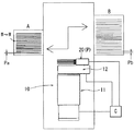
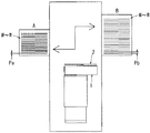
次に、本発明の実施形態を図1〜図9に基づいて具体的に説明する。以下説明する本実施形態の搬送装置10は、昇降装置11に支持された水平多関節ロボット12のアーム先端に装着した把持装置20がピッチ可変機構Pを備えた点に特徴を有している。
昇降装置11及び水平多関節ロボット12については、特に変更を要しないので詳細な説明は省略するが、昇降装置11の作動により水平多関節ロボット12が一定の範囲で昇降され、収納棚Aと収納棚Bとの間の適切な高さで当該水平多関節ロボット12が作動することにより板材W〜Wが以下説明する把持装置20に把持されて搬出側の収納棚Aから搬入側の収納棚Bへ搬送される。
収納棚A,Bには、それぞれ複数の板材W〜Wがその板厚方向を上下方向にして並列状態で収納される。収納棚Aでは、各板材W,W間の間隔がPaに設定され、収納棚Bでは各板材W,W間の間隔がPbに設定されている。本実施形態では、収納棚BのワークピッチPbが収納棚AのワークピッチPaよりも大きい場合を例示する。
図2及び図3には、本実施形態に係る把持装置20の詳細が示されている。この把持装置20は、水平多関節ロボット12のアーム12aの先端に支持されている。
アーム12aの先端にはベース21が支持されている。このベース21の上面にピッチ可変機構Pが構成されている。ベース21の上面には、左右一対の側壁部22,23が相互に一定の間隔をおいて平行に上方へ立ち上がる状態に設けられている。
この両側壁部22,23の内側(相互の対向面)には、それぞれ1本の案内レール24,25が取り付けられている。両案内レール24,25は、相互に対向した状態で上下方向に沿って固定されている。両案内レール24,25には、それぞれ4個のスライド体24a〜24d、25a〜25dが支持されている。合計8個のスライド体24a〜24d、25a〜25dは、それぞれ独立して案内レール24,25に沿って上下に移動可能に支持されている。
Next, an embodiment of the present invention will be specifically described with reference to FIGS. The
The
In the storage shelves A and B, a plurality of plate materials W to W are stored in a parallel state with the plate thickness direction being the vertical direction. In the storage shelf A, the interval between the plate members W, W is set to Pa, and in the storage shelf B, the interval between the plate members W, W is set to Pb. In this embodiment, the case where the work pitch Pb of the storage shelf B is larger than the work pitch Pa of the storage shelf A is illustrated.
2 and 3 show details of the
A
One
最も下側のスライド体24d,25dを介して第2枠体32が上下に平行移動可能に支持され、その上側のスライド体24c,25cを介して第3枠体33が上下に平行移動可能に支持され、その上側のスライド体24b,25bを介して第4枠体34が上下に平行移動可能に支持され、最も上側のスライド体24a,25aを介して第5枠体35が上下に平行移動可能に支持されている。
第2〜第5枠体32〜35は、それぞれ平面視矩形に枠組みされたもので、第2枠体32の側枠部32b,32cの外面にスライド体24d,25dが固定され、第3枠体33の側枠部33b,33cの外面にスライド体24c,25cが固定され、第4枠体34の側枠部34b,34cの外面にスライド体24b,25bが固定され、第5枠体35の側枠部35b,35cの外面にスライド体24a,25aが固定されている。
また、各枠体32〜35の前部にはそれぞれ前枠部32d〜35dが設けられている。第2枠体32の側枠部32b,32cの前部間は前枠部32dを介して相互に結合され、第3枠体33の側枠部33b,33cの前部間は前枠部33dを介して相互に結合され、第4枠体34の側枠部34b,34cの前部間は前枠部34dを介して相互に結合され、第5枠体35の側枠部35b,35c前部間は前枠部35dを介して相互に結合されている。
各前枠部32d〜35dに、それぞれ平面視U字形をなす保持板32a〜35aが前方へ張り出す状態に取り付けられている。
図4に示すように各枠体32〜35の側枠部32b,32c、33b,33c、34b,34c、35b,35cは、側面視それぞれ異なる曲線に沿って湾曲している。これにより、各枠体32〜35の前枠部32d〜35dは、その板厚方向(上下方向)に接近した状態となっている。
また、図3に示すように第3及び第4枠体33,34の左右幅(側枠部33b,33c間の間隔、側枠部34b,34c間の間隔)は、第2及び第5枠体32,35の左右幅(側枠部32b,32c間の間隔、側枠部35b,35c間の間隔)よりも大きく設定されている。これにより第2枠体32は第3枠体33に対してその側壁部の干渉が回避され、第5枠体35は第4枠体34に対してその側壁部の干渉が回避されて、上記したように前枠部32d〜35dをその板厚方向に接近させることができるようになっている。
The
The second to
Further,
Retaining
As shown in FIG. 4, the
Further, as shown in FIG. 3, the left and right widths of the third and
次に、ベース21の前部には、台座ブロック26が固定されている。この台座ブロック26の上面には、第1枠体31が固定されている。この第1枠体31に平面視U字形をなす第1保持板31aが同じく前方へ張り出す状態に取り付けられている。第1枠体31は、前記第2〜第5枠体32〜35の前枠部32d〜35dに相当する部材で、第2〜第5枠体32〜35の側枠部32b,32c、33b,33c、34b,34c、35b,35c及び後述する後枠部32e,33e,34e,35eに相当する部材を備えていない。このため、第1枠体31及び第1保持板31aは、第2〜第5枠体32〜35及び第2〜第5保持板32a〜35aとは異なって、上下方向に変位しないよう台座ブロック26を介してベース21上に固定されている。
このように設けられた第1〜第5保持板31a〜35aは、第1枠体31に対して第2〜第5枠体32〜35が上下方向に変位することにより、相互間の間隔が変化するようになっている。
第2枠体32の側枠部32b,32cの後端部間は、後枠部32eを介して結合されている。第3枠体33の側枠部33b,33cの後端部間は、後枠部33eを介して結合されている。第4枠体34の側枠部34b,34cの後端部間は、後枠部34eを介して結合されている。第5枠体35の側枠部35b,35cの後端部間は、後枠部35eを介して結合されている。
図2,6,7に示すように各後枠部32e,33e,34e,35eのほぼ中央には、係合部32f,33f,34f,35fが設けられている。各係合部32f,33f,34f,35fには、係合孔32g,33g,34g,35gが形成されている。各係合孔32g,33g,34g,35gは、前後方向に長い長溝孔形状に形成されている。各係合孔32g,33g,34g,35gには、後述する作動レバー40に取り付けた係合ローラ42〜45が挿入されている。
Next, a
The first to
The rear end portions of the
As shown in FIGS. 2, 6, and 7, engaging
次に、前記左右の側壁部22,23の後端上部は、連結板41を介して相互に結合されている。この連結板41の後面ほぼ中央には、支持ブロック46が後方へ突き出す状態に固定されている。この支持ブロック46には、支軸47を介して作動シリンダ50の上部(ヘッド側)が上下に傾動可能に支持されている。本実施形態の場合、作動シリンダ50には、圧縮エアにより伸縮作動する直動型のエアシリンダが用いられている。
一方、ベース21上には、回動ブロック27が固定されている。この回動ブロック27には、支軸48を介して上記作動レバー40が上下に回動可能に支持されている。この作動レバー40は、レバー片40aとこれよりも短いレバー片40bからなる概ねL字形を有している。レバー片40aとレバー片40bとの境界部(L字形の角部)において、当該作動レバー40が支軸48を介して支持されている。
作動レバー40の短いレバー片40bの先端には、支軸49を介して上記作動シリンダ50のロッド先端が回動可能に連結されている。このため、作動シリンダ50が伸縮作動してロッドがその軸方向にストロークされると、当該作動レバー40が支軸48を中心にして前後方向(図2において左右方向)に回動する。
作動レバー40のレバー片40aに、上記した合計4個の係合ローラ42〜45がそれぞれ回転可能に取り付けられている。4個の係合ローラ42〜45には、全て同じ径のものが用いられている。作動レバー40の回動中心(支軸48)から、軸間距離Rの位置に第2係合ローラ42が支持されている。また、第2〜第5係合ローラ42〜45は相互に軸間距離Rをおいて等間隔かつ同一軸線上に沿って配置されている。すなわち、第2係合ローラ42に対して第3係合ローラ43は軸間距離Rの位置に支持され、第3係合ローラ43に対して第4係合ローラ44は軸間距離Rの位置に支持され、第4係合ローラ44に対して第5係合ローラ45は軸間距離Rの位置に支持されている。従って、第3係合ローラ43は支軸48に対して軸間距離2Rの位置に支持され、第4係合ローラ44は支軸48に対して軸間距離3Rの位置に支持され、第5係合ローラ45は支軸48に対して軸間距離4Rの位置に支持されている。第5係合ローラ45がレバー片40aの回動先端側に支持されている。
このため、作動レバー40の回動に伴い、第2係合ローラ42は半径Rの円弧に沿って移動し、第3係合ローラ43は半径2Rの円弧に沿って移動し、第4係合ローラ44は半径3Rの円弧に沿って移動し、第5係合ローラ45は半径4Rの円弧に沿って移動する。
Next, upper rear end portions of the left and right
On the other hand, a
The rod tip of the working
A total of four
For this reason, the
第2係合ローラ42は第2枠体32の係合孔32gに挿入され、第3係合ローラ43は第3枠体33の係合孔33gに挿入され、第4係合ローラ44は第4枠体34の係合孔34gに挿入され、第5係合ローラ45は第5枠体35の係合孔35gに挿入されている。このため、作動シリンダ50の伸縮作動により作動レバー40が回動すると、そのレバー片40aが支軸48を中心にして前後に傾動することにより第2〜第5係合ローラ42〜45がそれぞれの円弧移動半径R,2R,3R,4Rで同時に円弧移動する。第2〜第5係合ローラ42〜45は、それぞれ前後に長い係合孔32g,33g,34g,35gに挿入されているため、各係合ローラ42〜45の円弧移動のうち上下方向(板材Wの板厚方向)の成分のみが各係合部32f,33f,34f,35fを経て第2〜第5枠体32〜35に伝達され、従って当該第2〜第5枠体32〜35ひいては第2〜第5保持板32a〜35aが板材Wの板厚方向に平行移動する。
第2〜第5保持板32a〜35aの移動距離L2〜L5は、係合ローラ42〜45の円弧移動半径R〜4RがR<2R<3R<4Rの関係を有していることから、L2<L3<L4<L5となる。しかも、本実施形態では、後述するようにL3=2×L2、L4=3×L2、L5=4×L2の関係となるよう各係合ローラ42〜45の円弧移動半径R〜4Rが設定(係合ローラ42〜45が等間隔に設定)されている。
The
The moving distances L2 to L5 of the second to
図6に示すように作動シリンダ50がロッド引き込み側(ロッドを引き込む方向)に作動すると、作動レバー40のレバー片40aが図6において実線で示すように反時計回り方向に一定角度傾動する。これにより各係合ローラ42〜45が下方へ変位することから、第2〜第5枠体32〜35ひいては第2〜第5保持板32a〜35aが下方すなわち第1保持板31aに接近する方向へ変位する。作動シリンダ50がロッド引き込み側のストローク端まで作動すると、第1保持板31aと第2保持板32aとの間隔、第2保持板32aと第3保持板33aとの間隔、第3保持板33aと第4保持板34aとの間隔、第4保持板34aと第5保持板35aとの間隔が全てL0(等ピッチ)となる。この間隔L0が収納棚Aにおける板材W,W間のピッチPaに設定(一致)されている。従って、第1〜第5保持板31a〜35aの間隔が全てL0の状態では、小さなピッチPaで収納された収納棚Aに対してワークW〜Wの搬出入を行うことができる。
これに対して、図2及び図7に示すように作動シリンダ50がロッド突き出し側(ロッドを突き出す方向)に作動すると、作動レバー40のレバー片40aが図2及び図7中実線で示すように時計回り方向に一定角度傾動する。これにより各係合ローラ42〜45が上方へ変位することから、第2〜第5枠体32〜35ひいては第2〜第5保持板32a〜35aが上方すなわち第1保持板31aから離間する方向へ変位する。作動シリンダ50がロッド突き出し側のストローク端まで作動した状態では、第1保持板31aと第2保持板32aとの間隔、第2保持板32aと第3保持板33aとの間隔、第3保持板33aと第4保持板34aとの間隔、第4保持板34aと第5保持板35aとの間隔が全て(L0+L2)(等ピッチ)となるよう、第2〜第5枠体32〜35の移動距離L2〜L5ひいては各係合ローラ42〜45の円弧移動半径R〜4Rが設定されている。
As shown in FIG. 6, when the operating
On the other hand, as shown in FIGS. 2 and 7, when the operating
第1〜第5保持板31a〜35a間の間隔(L0+L2)が収納棚Bにおける板材W,W間のピッチPbに設定(一致)されている。従って、第1〜第5保持板31a〜35aの間隔が全て(L0+L2)の状態では、大きなピッチPbで収納された収納棚Bに対してワークW〜Wの搬出入を行うことができる。
図8には、作動シリンダ50の伸縮作動による第1〜第5保持板31a〜35aの移動距離の関係が示されている。上記したように板材W〜Wが小さなピッチPaで収納された収納棚Aに対して搬出入を行う場合には、作動シリンダ50がロッド引き込み側に作動されて図8において左側に示すように第1〜第5保持板31a〜35aの間隔が全てL0とされる。
これに対して板材W〜Wが大きなピッチPbで収納された収納棚Bに対して搬出入を行う場合には、作動シリンダ50がロッド突き出し側に作動されて図8において右側に示すように第1〜第5保持板31a〜35aの間隔が全て(L0+L2)とされる。第1〜第5保持板31a〜35aの間隔がL0から(L0+L2)になるためには、第2保持板32aの移動距離がL2に設定され、第3保持板33aの移動距離がL3(=2×L2)に設定され、第4保持板34aの移動距離がL4(=3×L2)に設定され、第5保持板35aの移動距離がL5(=4×L2)に設定されている。この条件が満たされるように各係合ローラ42〜45の円弧移動半径R,2R,3R,4R及びレバー片40aの傾動角度ひいては作動シリンダ50のストロークが適切に設定されている。
以上説明したようにそれぞれ相互に独立して上下方向(板厚方向)に平行移動可能に支持された第2〜第5保持板31a〜35a、レバー40及び作動シリンダ50が主として本実施形態におけるピッチ可変機構Pを構成している。
また、作動シリンダ50の突き出し側及び引き込み側のストローク端は、図示省略したストッパブロックによって規制されている。これにより、レバー片40aの傾動範囲ひいては第2〜第5保持板32a〜35aの位置(移動距離)が高精度で位置決めされるようになっている。
The interval (L0 + L2) between the first to
FIG. 8 shows the relationship of the movement distances of the first to
On the other hand, when carrying in / out with respect to the storage shelf B in which the plate materials W to W are stored at a large pitch Pb, the operating
As described above, the second to
Further, the stroke end of the working
次に、各保持板31a〜35aには、板材Wを一枚ずつ保持するための板材吸着機構60がそれぞれ設けられている。各板材吸着機構60は、概ね同様の構成を備えている。以下、図9に示すように第4保持板34aに設けた板材吸着機構60について説明する。
第4保持板34aの上面先端には2つの吸着孔61,61が設けられている。この両吸着孔61,61と、前枠部34dの後面との間は吸気路62を経て連通されている。この吸気路62には、前枠部34dの後面に取り付けた継手63を介して分岐ホース64が接続されている。この分岐ホース64は、マニホールド65を経てメインホース66に接続されている。図示は省略されているが第1〜第5保持板31a〜35aの板材吸着機構60における合計5本の分岐ホース64〜64がマニホールド65に接続され、これら5本の分岐ホース64〜64が1本のメインホース66に接続されている。メインホース66は、ロボット12側に設けた真空発生器(図示省略)に接続されている。第1〜第5保持板31a〜35aの上面に一枚ずつ板材Wが載せ掛けられた状態で真空発生器が作動すると、第1〜第5保持板31a〜35aの各吸着孔61,61を経て板材Wが吸着保持される。
把持装置20における作動シリンダ50の作動、上記真空発生器の作動は、それぞれ昇降装置11及びロボット12の作動を制御する制御装置Cによりそれぞれ同期制御される。
また、第2〜第5枠体32〜35、作動シリンダ50、作動レバー40及びこれらの周辺は、カバー55内に収容されている。このカバー55はベース21の上方を覆う状態に取り付けられている。
Next, each holding
Two suction holes 61, 61 are provided at the top end of the upper surface of the
The operation of the
Further, the second to
以上のように構成した本実施形態の搬送装置10によれば、収納棚A側の5枚の板材W〜Wが搬送装置10により一度に取り出され、その後昇降装置11及びロボット12の作動により収納棚B側に収納される。搬入側の収納棚BのワークピッチPbは、搬出側の収納棚AのワークピッチPaよりも大きくなっている。
先ず、把持装置20において作動シリンダ50がロッド引き込み側に作動される。これにより、各保持板31a〜35aの間隔が全てL0(=ワークピッチPa)に切り換えられる。その後、昇降装置11の作動によりロボット12が収納棚Aと収納棚Bとの間において適切な高さに上昇され、次いでロボット12が作動して把持装置20の各保持板31a〜35aが収納棚AのワークW,W間に進入される。次に、昇降装置11が上昇側に僅かに作動することにより、各ワークWが保持板31a(又は32a,33a,34a,35a)によって持ち上げられる。しかる後に、真空発生器が作動して5枚の板材W〜Wが第1〜第5保持板31a〜35aの上面に吸着保持される。
According to the
First, the operating
こうして収納棚Aの5枚の板材W〜Wが把持装置20に吸着保持された後、ロボット12が作動して5枚の板材W〜Wが収納棚Aから取り出され、次いでロボット12及び昇降装置11が作動することによりこの5枚の板材W〜Wが収納棚b側に搬送される。この時、把持装置20の作動シリンダ50がロッド突き出し側に作動されて、第1〜第5保持板31a〜35aの間隔が全て(L0+L2)(=ワークピッチPb)に切り換えられ、従って吸着把持された5枚の板材W〜Wの間隔がピッチPaからピッチPbに切り換えられる。ピッチ変更後、ロボット12の作動により各板材Wの収納棚Bに対する位置決めがなされた後、各板材Wが収納棚Bに収納される。板材W〜Wの収納後、真空発生器が停止されて、第1〜第5保持板31a〜35aの板材W〜Wに対する吸着保持が解除され、しかる後にロボット12が後退し、さらに昇降装置11が作動することにより当該搬送装置10が初期位置に戻される。
上記とは逆に、収納棚Bの板材W〜Wを収納棚A側に搬送する場合には、先に把持装置20の作動シリンダ50がロッド突き出し側に作動されて第1〜第5保持体31a〜35aの間隔が(L0+L2)に切り換えられ、その後収納棚B側の5枚の板材W〜Wの搬送途中において作動シリンダ50がロッド引き込み側に作動されて吸着把持した板材W〜Wの間隔がL0に切り換えられる。
After the five plate members W to W of the storage shelf A are sucked and held by the gripping
Contrary to the above, when the plate members W to W of the storage shelf B are transported to the storage shelf A side, the operating
以上説明したように、本実施形態に係る搬送装置10によれば、把持装置20の1本の作動シリンダ50を作動させることにより、5枚の板材W〜Wを一度に吸着把持する第1〜第5保持板31a〜35aの間隔をL0と(L0+L2)とに瞬時に切り換えることができ、この切り換え動作はそれぞれ板材Wを吸着把持した状態のままでなされる。このため、従来電動モータを用いたピッチ可変形の把持装置に比してより簡易かつ低コストな構成でワークピッチが異なる2つの収納棚A,B間で複数の板材を搬出入することができる。
As described above, according to the
以上説明した実施形態には種々変更を加えることができる。例えば、作動シリンダ50をロッド突き出し側のストローク端とロッド引き込み側のストローク端との2位置間で作動させて2つのワークピッチPa,Pbに切り換える構成を例示したが、その中途位置においてロッドを停止可能な中間停止タイプの作動シリンダを用いることにより、3種類以上のワークピッチに対応可能な構成とすることができる。
また、第1〜第5保持板31a〜35aの間隔が全てL0若しくは全て(L0+L2)となる構成を例示したが、レバー片40aに対する各係合ローラ42〜45間の間隔を変更することにより、保持板相互間の間隔を不揃いにすることもできる。
さらに、5枚の板材W〜Wを一度に把持する構成を例示したが、2枚〜4枚あるいは6枚以上の板材を一度に把持する構成とすることもでき、これらの場合であっても各板材間の間隔を複数ピッチに切り換え可能な構成とすることができる。
また、作動シリンダ50を作動させることなく、第1〜第5保持板31a〜35aの間隔をL0若しくは(L0+L2)に固定しておくことにより、ワークピッチが同じ収納棚間において5枚の板材W〜Wを一度に搬送することができる。
また、板材がその板厚方向を上下方向にして収納される収納棚A,Bに対して搬出入する場合を例示したが、本発明に係る搬送装置は、板厚方向を水平方向にして並列状態に多数の板材が収納される収納棚に対しても適用することができる。この場合、ベース21上に把持装置が例示した姿勢に対して90°横倒しの状態で支持された構成とすればよい。
さらに、水平多関節型のロボット12を用いる構成を例示したが、これに代えて極座標型のロボットあるいはラック・ピニオン機構やシリンダ等の直動機構等を把持装置20の移動手段として用いる構成としてもよい。
Various modifications can be made to the embodiment described above. For example, the
Moreover, although the configuration in which the intervals between the first to
Furthermore, although the structure which hold | grips the 5 board | plate materials WW at the time was illustrated, it can also be set as the structure which hold | grips 2-4 sheets or 6 or more board | plate materials at a time, Even in these cases It can be set as the structure which can switch the space | interval between each board | plate material to several pitches.
Further, by fixing the interval between the first to
Moreover, although the case where a board | plate material carries in / out with respect to the storage shelves A and B accommodated by making the plate | board thickness direction into an up-down direction was illustrated, the conveying apparatus which concerns on this invention is parallel in the plate | board thickness direction. The present invention can also be applied to a storage shelf in which a large number of plates are stored in a state. In this case, what is necessary is just to set it as the structure supported on the base 21 in the state inclined 90 degrees with respect to the attitude | position which the holding | grip apparatus illustrated.
Further, the configuration using the horizontal articulated
P…ピッチ可変機構
W…板材
A…収納棚(ワークピッチPa)
B…収納棚(ワークピッチPb)
1…搬送装置(板材を一枚ずつ搬送するタイプ)
2…把持装置(板材を一枚ずつ搬送するタイプ)
10…搬送装置
11…昇降装置
12…水平多関節ロボット
20…把持装置
31…第1枠体、31a…第1保持板
32…第2枠体、32a…第2保持板、32g…係合孔
33…第3枠体、33a…第3保持板、33g…係合孔
34…第4枠体、34a…第4保持板、34g…係合孔
35…第5枠体、35a…第5保持板、35g…係合孔
L2〜L5…第2〜第5枠体の移動距離
40…レバー
42…第2係合ローラ
43…第3係合ローラ
44…第4係合ローラ
45…第5係合ローラ
R…第2係合ローラの円弧移動半径(各係合ローラ間の間隔)
2R…第3係合ローラの円弧移動半径
3R…第4係合ローラの円弧移動半径
4R…第5係合ローラの円弧移動半径
50…作動シリンダ
60…板材吸着機構
61…吸着孔
C…制御装置
P: Pitch variable mechanism W: Plate material A: Storage shelf (work pitch Pa)
B ... Storage shelf (work pitch Pb)
1 ... Conveying device (type that conveys plate material one by one)
2. Gripping device (type that conveys plate material one by one)
DESCRIPTION OF
2R:
Claims (3)
前記複数の板材を板厚方向に並列状態で保持する把持装置を備え、該把持装置は、前記板材を一枚ずつ把持する複数の把持板と、該複数の把持板の板厚方向のピッチを変更するピッチ可変機構を備え、該ピッチ可変機構は、前記複数の保持板に対してそれぞれ板厚方向に係合された共通の作動レバーを回動させてその板厚方向の変位成分により前記複数の保持板間のピッチを変更する構成とした搬送装置。 A conveying device that carries in and out a plurality of plate materials at a time with respect to a storage shelf that stores a plurality of plate materials in parallel in the plate thickness direction,
A gripping device that holds the plurality of plate members in parallel in the thickness direction, the gripping device includes a plurality of gripping plates that grip the plate materials one by one, and a pitch in the thickness direction of the plurality of gripping plates. The pitch variable mechanism includes a plurality of pitch variable mechanisms that rotate a common operating lever engaged with each of the plurality of holding plates in the plate thickness direction to change the plurality of pitches by a displacement component in the plate thickness direction. Conveying device configured to change the pitch between the holding plates.
The transport apparatus according to claim 1, wherein engagement positions of the operating levers with respect to the holding plates are set at equal intervals, and the plurality of holding plates are always arranged at an equal pitch.
Priority Applications (1)
| Application Number | Priority Date | Filing Date | Title |
|---|---|---|---|
| JP2006022558A JP2007204181A (en) | 2006-01-31 | 2006-01-31 | Conveying device for plate material |
Applications Claiming Priority (1)
| Application Number | Priority Date | Filing Date | Title |
|---|---|---|---|
| JP2006022558A JP2007204181A (en) | 2006-01-31 | 2006-01-31 | Conveying device for plate material |
Publications (1)
| Publication Number | Publication Date |
|---|---|
| JP2007204181A true JP2007204181A (en) | 2007-08-16 |
Family
ID=38483981
Family Applications (1)
| Application Number | Title | Priority Date | Filing Date |
|---|---|---|---|
| JP2006022558A Pending JP2007204181A (en) | 2006-01-31 | 2006-01-31 | Conveying device for plate material |
Country Status (1)
| Country | Link |
|---|---|
| JP (1) | JP2007204181A (en) |
Cited By (3)
| Publication number | Priority date | Publication date | Assignee | Title |
|---|---|---|---|---|
| JP2009260252A (en) * | 2008-03-27 | 2009-11-05 | Dainippon Screen Mfg Co Ltd | Substrate treatment device, its method, and substrate transport device |
| JP2010179419A (en) * | 2009-02-06 | 2010-08-19 | Nidec Sankyo Corp | Industrial robot |
| JP2010179420A (en) * | 2009-02-06 | 2010-08-19 | Nidec Sankyo Corp | Industrial robot |
Citations (5)
| Publication number | Priority date | Publication date | Assignee | Title |
|---|---|---|---|---|
| JPH02276261A (en) * | 1989-04-18 | 1990-11-13 | Kokusai Electric Co Ltd | Semiconductor wafer transfer device |
| JPH06183512A (en) * | 1992-12-15 | 1994-07-05 | M C Electron Kk | Pitch changer |
| JP2000174099A (en) * | 1998-12-01 | 2000-06-23 | Koyo Thermo System Kk | Thin-plate member-transferring device |
| JP2005116807A (en) * | 2003-10-08 | 2005-04-28 | Kawasaki Heavy Ind Ltd | Substrate-holding system |
| JP2006332590A (en) * | 2005-05-27 | 2006-12-07 | Win Tech | Semiconductor wafer transferring device |
-
2006
- 2006-01-31 JP JP2006022558A patent/JP2007204181A/en active Pending
Patent Citations (5)
| Publication number | Priority date | Publication date | Assignee | Title |
|---|---|---|---|---|
| JPH02276261A (en) * | 1989-04-18 | 1990-11-13 | Kokusai Electric Co Ltd | Semiconductor wafer transfer device |
| JPH06183512A (en) * | 1992-12-15 | 1994-07-05 | M C Electron Kk | Pitch changer |
| JP2000174099A (en) * | 1998-12-01 | 2000-06-23 | Koyo Thermo System Kk | Thin-plate member-transferring device |
| JP2005116807A (en) * | 2003-10-08 | 2005-04-28 | Kawasaki Heavy Ind Ltd | Substrate-holding system |
| JP2006332590A (en) * | 2005-05-27 | 2006-12-07 | Win Tech | Semiconductor wafer transferring device |
Cited By (3)
| Publication number | Priority date | Publication date | Assignee | Title |
|---|---|---|---|---|
| JP2009260252A (en) * | 2008-03-27 | 2009-11-05 | Dainippon Screen Mfg Co Ltd | Substrate treatment device, its method, and substrate transport device |
| JP2010179419A (en) * | 2009-02-06 | 2010-08-19 | Nidec Sankyo Corp | Industrial robot |
| JP2010179420A (en) * | 2009-02-06 | 2010-08-19 | Nidec Sankyo Corp | Industrial robot |
Similar Documents
| Publication | Publication Date | Title |
|---|---|---|
| CN102105375B (en) | Apparatus and method for transferring board-like work | |
| JP4596375B2 (en) | Articulated robot | |
| US10870206B2 (en) | Workpiece gripping device | |
| JP6619560B2 (en) | Bending machine | |
| JP2008213060A (en) | Articulated robot | |
| CN102057477A (en) | Stage with alignment function, treatment device equipped with stage with the alignment function, and substrate alignment method | |
| WO2015087854A1 (en) | Robot hand, robot, and robot cell | |
| JP2007283436A (en) | Robot, robot system, and attitude control method of hand device | |
| TW201617192A (en) | Robot and robot system | |
| JP6366932B2 (en) | Work reversal support device and robot cell equipped with the same | |
| CN108466511A (en) | Glass carving machine assembly line | |
| JP5263945B2 (en) | Double arm robot | |
| JP2007204181A (en) | Conveying device for plate material | |
| WO2007091503A1 (en) | Robot device | |
| WO2012111166A1 (en) | Pallet transfer apparatus for working machine | |
| KR100863432B1 (en) | Shuttle device for pallet | |
| CN108349088A (en) | The teaching method of robot, the control method of robot, teaching fixture and robot | |
| US10144127B2 (en) | Transfer apparatus | |
| JP4593536B2 (en) | Attitude change device and substrate transfer device | |
| JP2007260862A (en) | Robot | |
| JPH08216073A (en) | Robot for work carrying-in/carrying-out work | |
| JPH06320363A (en) | Part automatic assembling device | |
| JP7031129B2 (en) | Transport system | |
| KR100760200B1 (en) | Robot for conveyance | |
| JP2002103166A (en) | Gantry loader device |
Legal Events
| Date | Code | Title | Description |
|---|---|---|---|
| A621 | Written request for application examination |
Free format text: JAPANESE INTERMEDIATE CODE: A621 Effective date: 20081009 |
|
| A977 | Report on retrieval |
Effective date: 20110203 Free format text: JAPANESE INTERMEDIATE CODE: A971007 |
|
| A131 | Notification of reasons for refusal |
Effective date: 20110614 Free format text: JAPANESE INTERMEDIATE CODE: A131 |
|
| A02 | Decision of refusal |
Effective date: 20111025 Free format text: JAPANESE INTERMEDIATE CODE: A02 |