JP2007194166A - Vehicular lamp - Google Patents
Vehicular lamp Download PDFInfo
- Publication number
- JP2007194166A JP2007194166A JP2006013462A JP2006013462A JP2007194166A JP 2007194166 A JP2007194166 A JP 2007194166A JP 2006013462 A JP2006013462 A JP 2006013462A JP 2006013462 A JP2006013462 A JP 2006013462A JP 2007194166 A JP2007194166 A JP 2007194166A
- Authority
- JP
- Japan
- Prior art keywords
- light
- reflecting surface
- projection lens
- reflector
- shutter
- Prior art date
- Legal status (The legal status is an assumption and is not a legal conclusion. Google has not performed a legal analysis and makes no representation as to the accuracy of the status listed.)
- Pending
Links
Images


Abstract
Description
本発明は、例えば自動車の前部に設けられた前照灯または補助前照灯として使用される車両前照灯に関する。 The present invention relates to a vehicle headlamp used, for example, as a headlamp or an auxiliary headlamp provided at the front of an automobile.
従来、所謂プロジェクタタイプの自動車用の前照灯は、光源バルブとしてバルブと、バルブからの光を前方に向かって反射させる反射面と、バルブまたは反射面からの光を集束させる投影レンズと、バルブから投影レンズへの光路中に配置された所謂カットオフラインを形成するためのシャッタと、から構成されている。
ここで、上記バルブは、その中心軸が前方に向かってほぼ水平に延びる投影レンズの光軸と一致するように、前向きに配置されている。
2. Description of the Related Art Conventionally, a so-called projector-type automotive headlamp includes a bulb as a light source bulb, a reflective surface that reflects light from the bulb forward, a projection lens that focuses the light from the bulb or the reflective surface, and a bulb. And a shutter for forming a so-called cut-off line disposed in the optical path from the projection lens to the projection lens.
Here, the bulb is disposed forward so that the central axis thereof coincides with the optical axis of the projection lens extending substantially horizontally toward the front.
このような構成の前照灯によれば、バルブから出射した光が、直接にまたは上記反射面で反射されて投影レンズに入射し、投影レンズによって集束されることにより、前方に向かって照射される。
その際、投影レンズに入射する光の一部がシャッタによって遮断されることにより、対向車に幻惑光を与えないように対向車線側で照射距離が短くなるような所望の配光特性が得られ、所謂すれ違いビームが形成されるようになっている。
According to the headlamp having such a configuration, the light emitted from the bulb is reflected directly or reflected by the reflecting surface, enters the projection lens, and is focused forward by the projection lens. The
At that time, a part of the light incident on the projection lens is blocked by the shutter, so that a desired light distribution characteristic is obtained such that the irradiation distance is shortened on the oncoming lane side so as not to give a dazzling light to the oncoming vehicle. A so-called passing beam is formed.
しかしながら、このような構成の前照灯においては、上述したように、バルブが前向きに配置されていることから、灯具全体の前後方向の全長が比較的長くなってしまい、自動車の車体に対する取付スペースが大きくなると共に、取付の自由度が小さく、自動車の車体デザイン上の制約となってしまう。 However, in the headlamp having such a configuration, as described above, since the bulb is disposed forward, the entire length of the entire lamp in the front-rear direction becomes relatively long, and the mounting space for the vehicle body of the automobile Increases, and the degree of freedom in mounting is small, which is a restriction on the vehicle body design.
これに対して、特許文献1及び特許文献2には、バルブを光軸の側方から挿入(横向き)にして、さらに投影レンズの光軸より下方に配置するようにした、車両前照灯が開示されている。
このような構成によれば、一定の長さを持つバルブが横向きに配置されていることにより、灯具の全長が短縮され、小型に構成され得ることになる。
On the other hand, in
According to such a structure, since the bulb | bulb with fixed length is arrange | positioned sideways, the full length of a lamp can be shortened and it can be comprised small.
さらに、特許文献1による車両前照灯においては、可動式シャッタを設けて、このシャッタを投影レンズへの光路中に挿入することにより、シャッタ端縁によりカットオフラインを形成して、すれ違いビームの配光特性を得ると共に、上記シャッタを光路から退避させることにより、走行ビームの配光特性を得るようにしている。
Further, in the vehicle headlamp according to
また、特許文献2による車両前照灯においては、光源バルブから反射面そして投影レンズを介して前方に照射される主配光以外の光を、付加リフレクタにより車両前方に向けて投影レンズを介さず反射させることにより、光源バルブからの光を有効利用して、より視認性の良好な配光特性を得るようにしている。
ところで、上記バルブは、一般的にその中心軸付近に最大光度を与えるような発光特性を有している。
これに対して、特許文献1及び特許文献2によるプロジェクタタイプの車両前照灯においては、バルブの発光中心が光軸の直下に位置するように配置されていると共に、バルブから中心軸方向に出射して反射面の光軸側方領域で反射された光は、投影レンズを透過した後、配光パターンにおける側方領域、所謂拡散領域に出射されることになる。
このため、バルブの最大光度を与える光が、前方の配光中心付近に向かって照射されないため、配光パターンにおける中心付近の最大光度が低くなる。
従って、従来の光源バルブが光軸方向に沿って配置されている通常のプロジェクタタイプの車両前照灯と比較して、前方の配光中心に向かって照射される光束が少なくなると共に、最大高度が低下してしまう。
By the way, the bulb generally has a light emission characteristic that gives the maximum luminous intensity near the central axis.
On the other hand, in the projector-type vehicle headlamps disclosed in
For this reason, since the light which gives the maximum luminous intensity of the bulb is not irradiated toward the vicinity of the front light distribution center, the maximum luminous intensity near the center in the light distribution pattern is lowered.
Therefore, compared with a normal projector-type vehicle headlamp in which conventional light source bulbs are arranged along the optical axis direction, the amount of light emitted toward the front light distribution center is reduced and the maximum altitude is increased. Will fall.
また、特許文献1による車両前照灯においては、可動シャッタにより、すれ違いビームと走行ビームを切換えるようにしているが、横向きに光源を挿入することで光束最大光度が不足するため一つの光源バルブ,反射面及び投影レンズによりすれ違いビーム及び走行ビームの双方の配光特性を十分に満足することは困難であった。
Further, in the vehicle headlamp according to
これに対して、特許文献2による車両前照灯においては、付加リフレクタにより光源バルブからの光を有効利用するようにしているが、付加リフレクタで反射された光は、配光パターンの外縁を照射するため配光特性の中心付近の光度を高めるようには構成されていないので、同様に前方に向かって照射される光束が少なくなると共に、最大高度が低下してしまう。
On the other hand, in the vehicle headlamp according to
本発明は、以上の点から、簡単な構成により、配光パターンにおける中心付近の最大光度を高めると共に、照射光の全光束を増大させるようにした、バルブ横置き型のプロジェクタタイプ車両前照灯を提供することを目的としている。 In view of the above, the present invention is a projector-type vehicle headlamp of a bulb lateral type that increases the maximum luminous intensity near the center of the light distribution pattern and increases the total luminous flux of the irradiated light with a simple configuration. The purpose is to provide.
上記目的は、本発明の構成によれば、照射方向に水平に延びる光軸上に配置された凸形の投影レンズと、この投影レンズの後側の焦点位置の後方にてほぼ光軸と直交する向きに配置された光源バルブと、この光源バルブから出射する光を反射して上記投影レンズの照射方向後側の焦点位置付近に向かって集束する主リフレクタと、この光源バルブから出射する光のうち前方やや上向きに出射する光を下方に反射する第一の反射面と、この第一の反射面からの光を照射方向前方の配光中心付近に向かって反射する第二の反射面とを有する副リフレクタと、上記投影レンズの後側焦点位置付近に配置され当該投影レンズへの光路の少なくとも一部を遮蔽する第一の遮光部と、副リフレクタの上記第一の反射面から第二の反射面に反射される光路の少なくとも一部を遮蔽する第二の遮光部とを有するシャッタと、を備え、上記シャッタが、上記第一の遮光部が主リフレクタから投影レンズへの光路上にてすれ違いビーム用のカットオフを形成し上記第二の遮光部が副リフレクタの上記第一の反射面から第二の反射面に反射される光路の少なくとも一部を遮蔽する挿入位置と、上記投影レンズ及び副リフレクタの第二の反射面の光路を解放する退避位置との間で可動する車両用前照灯、により達成される。 According to the configuration of the present invention, the above object is achieved by a convex projection lens disposed on an optical axis extending horizontally in the irradiation direction, and substantially orthogonal to the optical axis behind the focal position on the rear side of the projection lens. A light source bulb arranged in a direction, a main reflector that reflects the light emitted from the light source bulb and focuses the light toward the focal position on the rear side in the irradiation direction of the projection lens, and the light emitted from the light source bulb. Of these, a first reflecting surface that reflects light emitted upward slightly forwardly and a second reflecting surface that reflects light from the first reflecting surface toward the vicinity of the light distribution center forward in the irradiation direction. A sub-reflector having a first light-shielding portion that is disposed in the vicinity of the rear focal position of the projection lens and shields at least part of the optical path to the projection lens; and a second reflector from the first reflecting surface of the sub-reflector. Of the light path reflected by the reflecting surface A shutter having a second light-shielding portion that shields at least a part of the shutter, and the shutter has a cutoff for the beam that the first light-shielding portion passes on the optical path from the main reflector to the projection lens. An insertion position where the second light-shielding portion shields at least part of an optical path reflected from the first reflecting surface of the sub-reflector to the second reflecting surface; and a second position of the projection lens and the sub-reflector This is achieved by a vehicular headlamp that moves between a retracted position that releases the optical path of the reflecting surface.
本発明による車両用灯具は、好ましくは、上記シャッタが、挿入位置にあるときにはすれ違い配光を形成し、退避位置にあるときには走行用配光を形成する。 The vehicle lamp according to the present invention preferably forms a passing light distribution when the shutter is in the insertion position, and forms a traveling light distribution when the shutter is in the retracted position.
本発明による車両用灯具は、好ましくは、上記シャッタが、第二の遮光部の一部に開口部を有し、上記第二の遮光部が、挿入位置にあるときにはこの第二の遮光部によって副リフレクタの上記第一の反射面から第二の反射面に反射される光路の少なくとも一部を遮蔽し、退避位置にあるときには当該光路が上記開口部を通過する。 In the vehicle lamp according to the present invention, preferably, the shutter has an opening in a part of the second light shielding portion, and when the second light shielding portion is in the insertion position, the second light shielding portion At least a part of the optical path reflected from the first reflecting surface to the second reflecting surface of the sub-reflector is shielded, and when in the retracted position, the optical path passes through the opening.
本発明による車両用灯具は、好ましくは、上記第二の遮光部が、挿入位置にあるときには上記第二の遮光部によって副リフレクタの上記第一の反射面から第二の反射面に反射される光路を遮蔽し上記投影レンズからのみ照射する。 In the vehicular lamp according to the present invention, preferably, when the second light-shielding portion is in the insertion position, the second light-shielding portion reflects the second reflector from the first reflecting surface to the second reflecting surface. The optical path is shielded, and irradiation is performed only from the projection lens.
上記構成によれば、光源バルブから出射した光が、直接にまたは主リフレクタで反射されると共に、その第二の焦点位置即ち投影レンズの後側の焦点位置に向かって集束され、さらに投影レンズを介して前方に向かって照射される。
また、光源バルブから前側上方に出射して副リフレクタに入射した光は、副リフレクタで反射され、前方に向かって照射される。
According to the above configuration, the light emitted from the light source bulb is reflected directly or by the main reflector and is focused toward the second focal position, that is, the focal position on the rear side of the projection lens. It is irradiated toward the front through.
Further, the light emitted from the light source bulb to the upper front side and incident on the sub-reflector is reflected by the sub-reflector and irradiated forward.
ここで、走行ビーム時には、シャッタが退避位置に移動することにより、副リフレクタで反射された光は、シャッタにより遮断されることなく、その開口部を通過してそのまま前方の中心付近に向かって照射されることになる。本発明では、主リフレクタ及び副リフレクタで反射された光により、主リフレクタによる主配光パターンに加えて、副リフレクタによるスポット配光パターンが、中心付近に向かって照射される。これにより、本発明は中心付近の光度が高められることになり、走行ビームのために最適な配光パターンが得られることになる。 Here, at the time of traveling beam, the light reflected by the sub-reflector passes through the opening without being blocked by the shutter, and is irradiated toward the front center as it is because the shutter moves to the retracted position. Will be. In the present invention, in addition to the main light distribution pattern by the main reflector, the spot light distribution pattern by the sub reflector is irradiated toward the vicinity of the center by the light reflected by the main reflector and the sub reflector. As a result, the light intensity near the center of the present invention is increased, and an optimal light distribution pattern for the traveling beam can be obtained.
これに対して、すれ違いビーム時には、シャッタが挿入位置に移動されることにより、副リフレクタで反射された光は、シャッタにより遮断されるため、この副リフレクタからは、前方に向かって少なくとも一部が照射されない。
従って、主リフレクタで反射された光のみが投影レンズを介して前方に向かって照射され、その際シャッタによりカットオフラインを形成されることにより、すれ違いビームに適した配光パターンが得られることになる。
On the other hand, at the time of the low beam, since the shutter is moved to the insertion position, the light reflected by the sub-reflector is blocked by the shutter, so that at least a part of the sub-reflector is directed forward. Not irradiated.
Therefore, only the light reflected by the main reflector is irradiated forward through the projection lens, and at that time, a cut-off line is formed by the shutter, so that a light distribution pattern suitable for the low beam can be obtained. .
ここで、光源バルブがほぼ横向きに配置されていることによって、車両前照灯の灯具全体が比較的短く構成され得る。
また、シャッタが退避位置にあるときには、副リフレクタで反射された光が、配光パターンの中心付近の光度を高めることになり、走行ビームとして十分な光度が得られることになる。
Here, since the light source bulb is arranged substantially horizontally, the entire lamp of the vehicle headlamp can be configured to be relatively short.
In addition, when the shutter is in the retracted position, the light reflected by the sub-reflector increases the luminous intensity near the center of the light distribution pattern, and sufficient luminous intensity is obtained as a traveling beam.
上記副リフレクタが、上記光源バルブの前方にて、光源バルブから前方やや上向きに出射する光を上記シャッタの上方にて下方に向かって反射させる第一の反射面と、第一の反射面で反射された光を上記シャッタの下方にて前方に向かって反射させる第二の反射面と、から構成されている場合は、副リフレクタの第一の反射面及び第二の反射面により光源バルブからの光を二段階で反射させることにより、副リフレクタが比較的小型に構成され得ることになる。 The sub-reflector reflects the light emitted from the light source bulb in a slightly upward direction forward from the light source bulb and reflected by the first reflective surface and the first reflective surface. And a second reflecting surface that reflects forward light below the shutter toward the front, from the light source bulb by the first reflecting surface and the second reflecting surface of the sub-reflector. By reflecting light in two stages, the sub-reflector can be made relatively small.
上記副リフレクタの第一の反射面が、光源バルブ付近に第一の焦点を有し、且つ上記シャッタの退避位置にてその開口部の中心付近に第二の焦点を有する楕円系反射面として形成されており、上記副リフレクタの第二の反射面が、上記第一の反射面の第二の焦点付近に焦点を有する放物系反射面として形成されている場合には、副リフレクタの第一の反射面で反射された光が、その第二の焦点付近で集束された後、第二の反射面で反射されて前方に向かって照射される。
従って、光が最も集束される副リフレクタの第一の反射面の第二の焦点付近にて、シャッタの開口部が、この光を遮断または通過させることにより、開口部が光源バルブの像とほぼ同じ大きさでよいことから、比較的小さくて済むと共に、遮断または通過の切換えのためのシャッタの移動量も少なくて済み、シャッタ全体が小型化され得ることになる。
The first reflecting surface of the sub-reflector is formed as an elliptical reflecting surface having a first focal point near the light source bulb and having a second focal point near the center of the opening at the retracted position of the shutter. And when the second reflecting surface of the sub-reflector is formed as a parabolic reflecting surface having a focal point near the second focal point of the first reflecting surface, After the light reflected by the reflective surface is focused near the second focal point, the light is reflected by the second reflective surface and irradiated forward.
Therefore, in the vicinity of the second focal point of the first reflecting surface of the sub-reflector where the light is most focused, the opening of the shutter blocks or passes this light, so that the opening is almost the same as the image of the light source bulb. Since the same size is sufficient, the size of the shutter can be relatively small, and the amount of movement of the shutter for switching between blocking and passing can be reduced, and the entire shutter can be downsized.
このようにして、本発明によれば、光源バルブを横向きに配置したプロジェクタタイプの車両前照灯において、副リフレクタを付加して、この副リフレクタにより光源バルブからの光を前方に向かって照射することにより、従来利用されていない光源バルブからの光を走行ビームの配光パターンの中心付近に照射する。 Thus, according to the present invention, in the projector-type vehicle headlamp in which the light source bulb is disposed sideways, the auxiliary reflector is added, and the light from the light source bulb is irradiated forward by the auxiliary reflector. Thus, light from a light source bulb that has not been conventionally used is irradiated near the center of the light distribution pattern of the traveling beam.
これにより、走行ビーム時には、シャッタを退避位置に移動させて、副リフレクタからの反射光により走行ビームの配光パターンの中心付近の光度を高めることにより、光源バルブからの光の利用効率が向上し、配光パターンにおける中心付近の最大光度が高められ得ると共に、一つの灯体から照射される全光束が増大することになる。
また、すれ違いビーム時には、シャッタが挿入位置に移動することで、副リフレクタの第一の反射面からの反射光を遮断すると共に、このシャッタが主リフレクタからの反射光にカットオフラインを形成することにより、すれ違いビームに適した配光パターンが得られる。
As a result, at the time of the traveling beam, the use efficiency of light from the light source bulb is improved by moving the shutter to the retracted position and increasing the luminous intensity near the center of the light distribution pattern of the traveling beam by the reflected light from the sub-reflector. The maximum luminous intensity near the center in the light distribution pattern can be increased, and the total luminous flux emitted from one lamp body is increased.
In the case of a passing beam, the shutter moves to the insertion position, thereby blocking the reflected light from the first reflecting surface of the sub-reflector and forming a cutoff line in the reflected light from the main reflector. A light distribution pattern suitable for a passing beam can be obtained.
従って、本発明は一つの灯体(光源バルブ,主リフレクタ及び投影レンズ)により、走行ビーム及びすれ違いビームの双方に関して、それぞれ配光パターン及び中心付近の光度そして全光束が最適化され得ることになる。 Therefore, according to the present invention, the light distribution pattern, the luminous intensity near the center, and the total luminous flux can be optimized with respect to both the traveling beam and the low beam by one lamp body (light source bulb, main reflector and projection lens). .
以下、この発明の好適な実施形態を図1〜図5を参照しながら、詳細に説明する。
尚、以下に述べる実施形態は、本発明の好適な具体例であるから、技術的に好ましい種々の限定が付されているが、本発明の範囲は、以下の説明において特に本発明を限定する旨の記載がない限り、これらの態様に限られるものではない。
Hereinafter, preferred embodiments of the present invention will be described in detail with reference to FIGS.
The embodiments described below are preferable specific examples of the present invention, and thus various technically preferable limitations are given. However, the scope of the present invention particularly limits the present invention in the following description. As long as there is no description of the effect, it is not restricted to these aspects.
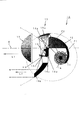
図1は、本発明による車両用灯具の一実施形態の構成を示している。
図1において、車両用灯具10は、自動車の前照灯であって、その構成要素として光源バルブとしてのバルブ11と、上記バルブ11からの光を前方に向かって反射させる主リフレクタ12と、バルブ11の前方に配置された投影レンズ13と、シャッタ14と、上記バルブ11の前方の上下にて配置された副リフレクタ15と、から構成されている。
FIG. 1 shows the configuration of an embodiment of a vehicular lamp according to the present invention.
In FIG. 1, a
上記バルブ11は、一般に自動車の前照灯または補助前照灯に使用されるバルブであって、例えば白熱電球,ハロゲン電球やメタルハライドランプ等の放電灯等のバルブが使用され、ソケット(不図示)により固定保持されると共に、給電されるようになっている。
この場合、上記バルブ11は、投影レンズ13の光軸Oに対して、ほぼ直交する(以下、「横向き」とも称する)に且つ車体側方の外側に向かって先端が延びるように、さらに図1のように上記光軸Oから下方にずれて、配置されている。
The
In this case, the
上記主リフレクタ12は、上記バルブ11の後方に配置されており、上記バルブ11から後側に出射する光を前方に向かって反射させるように前方L1に向かって凹状に形成され、その第一の焦点位置F1がバルブ11の発光中心11a付近に位置すると共に、その第二の焦点位置F2が前側にて上記光軸O上に位置するように、楕円系反射面から構成されている。
ここで、楕円系反射面は、回転楕円面,楕円柱だけでなく、楕円面を基本とした自由曲面を含むものである。
これにより、バルブ11から後方に出射した光は、上記主リフレクタ12で反射されて投影レンズ13の後側の焦点位置に向かって進み、さらにシャッタ14を介して投影レンズ13を透過して前方に向かって出射されるようになっている。
The main reflector 12 is disposed behind the
Here, the elliptical reflecting surface includes not only a spheroid and an elliptic cylinder but also a free-form surface based on an ellipsoid.
Thereby, the light emitted backward from the
上記投影レンズ13は、凸状のレンズから構成されており、その光源側の焦点が、上記光軸O上にて上記主リフレクタ12の第二の焦点位置F2付近に位置するように、配置されている。
The
上記シャッタ14は、不透光性材料から形成されていると共に、挿入位置(図2にて図示)と退避位置(図3にて図示)との間を図1で示すように移動し得るように構成されている。
The
そして、上記シャッタ14は、図2にて示された挿入位置において、その上縁14aが、上記投影レンズ13の光源側の焦点位置に位置し、例えばすれ違いビームの配光パターンにおけるカットオフラインを形成するようになっている。
また、上記シャッタ14は、図3にて点線で示された退避位置において、その上縁14aが、上記投影レンズ13の光路を開放し、主リフレクタ12で反射され投影レンズ13に入射する光を妨げないようになっている。
2, the upper edge 14a of the
Further, the
さらに、上記シャッタ14は、回動軸14dの下方にてほぼ水平方向に、そして副リフレクタ15の第一の反射面から第二の反射面への光軸に対してほぼ垂直に延びる遮光部14bを備えており、この遮光部14bのほぼ中心に開口部14cを備えている。
この遮光部14bは、上記シャッタ14が挿入位置にあるとき、副リフレクタ15の第一の反射面15aから第二の反射面15bへの光路を遮蔽する。
これに対して、上記シャッタ14が退避位置にあるとき、遮光部14bが光路から退き副リフレクタ15の第一の反射面15aから第二の反射面15bへの光路を開放するようになっている。
Further, the
The
On the other hand, when the
尚、上記シャッタ14は、図示の場合、回転軸14dを中心に揺動可能に支持されており、移動手段としての例えばソレノイド,モータ等の適宜の駆動手段により、上述した挿入位置と退避位置との間を移動され得るようになっている。
In the case shown in the drawing, the
上記副リフレクタ15は、上記バルブ11の光L1の照射方向の前方にてシャッタ14を挟んで上下に、そしてバルブ11または主リフレクタ12から投影レンズ13に入射する光を妨げないように配置された上方の第一の反射面15a及び下方の第二の反射面15bから構成されている。
The sub-reflector 15 is arranged above and below the
ここで、上記第一の反射面15aは、上記バルブ11からL1方向前方の上側に出射する光を下方に向かって反射させるように、後下方に向かって凹状に形成され、その第一の焦点位置F1がバルブ11の発光中心11a付近に位置すると共に、その第二の焦点位置F3が、上記シャッタ14の挿入位置における開口部14c付近に位置するように、楕円系反射面から構成されている。
これにより、バルブ11からL1方向前方の上側に出射した光は、上記副リフレクタ15の第一の反射面15aで反射され、その第二の焦点位置F3に向かって集束した後、第二の反射面15bに入射するようになっている。
Here, the first reflecting surface 15a is formed in a concave shape rearward and downward so as to reflect light emitted upward from the
Thereby, the light emitted from the
これに対して、上記第二の反射面15bは、上記シャッタ13の下方に配置されており、上側の副リフレクタ15の第一の反射面15aからの反射光を受けて前方の中心付近に向かって反射させるように、L1方向前方に向かって凹状に形成され、その焦点位置が上記第一の反射面15aの第二の焦点位置F3付近に位置すると共に、中心軸がOと平行な直線で前方に向かって延びる放物系反射面から構成されている。 ここで、放物系反射面は、回転放物面だけでなく、放物面を基本とした自由曲面を含むものである。
これにより、上記副リフレクタ15の第一の反射面15aで反射され、その第二の焦点位置F3に向かって集束した光は、第二の反射面15bで反射され、前方の中心付近に向かってスポット配光(中心付近に集光した配光)として照射されるようになっている。
On the other hand, the second reflecting
Thereby, the light reflected by the first reflecting surface 15a of the sub-reflector 15 and converged toward the second focal position F3 is reflected by the second reflecting
本発明実施形態による車両用灯具10は、以上のように構成されており、バルブ11がソケットから給電されて発光することにより、バルブ11から出射した光は、その一部の光L1が、図1に示すように、直接にまたは主リフレクタ12で反射されて、第二の焦点F2即ち投影レンズ13の後側の焦点位置付近に向かって進み、さらにシャッタ14を介して投影レンズ13により集束されながら、前方に向かって照射される。
The
ここで、走行ビーム時には、図2に示すように、上記シャッタ14が図示しない移動手段により退避位置に持ち来たされる。
これにより、バルブ11から前方上側に向かって出射する光L2は、副リフレクタ15の第一の反射面15aで反射されて、第二の反射面15bに向かって収束され、シャッタ14の開口部14cを通過した後、第二の反射面15bで反射されて、前方の中心付近に向かって照射される。
Here, during the traveling beam, as shown in FIG. 2, the
As a result, the light L2 emitted from the
このとき、前方上側に向かって照射される光L2は、主リフレクタ12で反射され投影レンズを介して前方に向かって照射される光L1が形成する配光パターンに対して、その配光パターン中央付近にスポット配光として付加的に照射されることになる。
従って、この副リフレクタ15a,bにより走行ビームの配光パターンにおける中心付近の最大光度がより高められると共に、全光束が増大するので、遠方視認性が向上することになる。
At this time, the light L2 irradiated toward the front upper side is the center of the light distribution pattern with respect to the light distribution pattern formed by the light L1 reflected by the main reflector 12 and irradiated forward through the projection lens. The light is additionally irradiated in the vicinity as a spot light distribution.
Therefore, the sub-reflectors 15a and 15b can further increase the maximum luminous intensity near the center of the light distribution pattern of the traveling beam and increase the total luminous flux, thereby improving the distance visibility.
これに対して、すれ違いビーム時には、図3に示すように、上記シャッタ14が図示しない移動手段により挿入位置に持ち来たされる。
これにより、シャッタ14の上縁14aが、投影レンズ13によって前方に向かって拡大して投影されることにより、配光パターンにおけるカットオフラインが形成され、すれ違いビームの配光パターンが得られることになる。
On the other hand, at the time of passing beam, as shown in FIG. 3, the
As a result, the upper edge 14a of the
また、バルブ11から前方上側に向かって出射する光L2は、副リフレクタ15の第一の反射面15aで反射されて、第二の反射面15bに向かって収束するが、上記シャッタ14の遮光部14bにより遮断されることになる。従って、この光L2は、前方に向かって照射されない。
これにより、バルブ11からの直接光及び主リフレクタ12による反射光即ち光L1に基づいて、すれ違いビームに最適な配光パターンが得られることになる。
The light L2 emitted from the
Thereby, based on the direct light from the
この場合、シャッタ14を移動手段によって退避位置と挿入位置との間を移動させることにより、簡単な構成により、すれ違いビームのためのカットオフラインの形成と、副リフレクタ15の光路の遮断が行なわれることになり、部品点数が少なくて済み、部品コスト及び組立コストが低減され得ることになる。
その際、副リフレクタ15の第一の反射面15aで反射された光L2は、シャッタ14の開口部14c付近にて集束されるので、開口部14cが小さくて済むと共に、開口部14cそしてシャッタ14の挿入位置と退避位置との間の移動量も小さくて済むことから、シャッタ14そしてその移動機構が小型に構成され得ることになる。
In this case, the
At this time, the light L2 reflected by the first reflecting surface 15a of the sub-reflector 15 is converged in the vicinity of the opening 14c of the
従って、車両用灯具10はバルブ11が横向きに配置されていることにより、灯具全体の長さが短く構成され得ると共に、主リフレクタ12の横方向への張り出し量が少なくて済み、全体に小型に構成され得ることになる。
さらに、シャッタ14の開口部14cが副リフレクタ15の光路に挿脱されることにより、配光パターンの中心付近の光度が切換えられ、走行ビーム時の中心付近の最大光度が高められるので、それぞれ走行ビーム及びすれ違いビームに最適な中心付近の最大光度が設定され、走行ビーム時の配光パターンの中心付近の最大光度が十分に高められ得ることになる。
Therefore, the
Further, the opening 14c of the
図4及び図5は、上述した車両前照灯10による配光パターンのシミュレーション結果を示している。
ここで、図4は、すれ違いビーム時における配光パターンを示している。
この場合、配光パターンは、バルブ11から直接にまたは主リフレクタ12により反射されて投影レンズ14を介して前方に出射される光L1により形成されている。
従って、従来の車両前照灯とほぼ同様に、シャッタ14の上縁14aによりカットオフラインが形成されていると共に、その中心付近の最大光度は、光L1のみによる配光パターンであることから、比較的低く設定されている。
4 and 5 show the simulation results of the light distribution pattern by the
Here, FIG. 4 shows a light distribution pattern at the time of the passing beam.
In this case, the light distribution pattern is formed by light L <b> 1 reflected directly from the
Accordingly, a cut-off line is formed by the upper edge 14a of the
これに対して、図5は、走行ビーム時における配光パターンを示している。
この場合、配光パターンは、バルブ11から直接にまたは主リフレクタ12により反射されて投影レンズ14を介して前方に出射される光L1による配光パターン(図5(A)参照)と、バルブ11から前方上側に向かって出射され、副リフレクタ15の第一の反射面15a及び第二の反射面15bにより反射され、前方の中心付近に出射される光L2によるスポット配光パターン(図5(B)参照)と、により形成される。
ここで、図5(C)に示すように、上述した光L1+L2による全体の配光パターンは、全光束が増大すると共に、配光パターンの中心付近の最大光度が十分に高められていることが分かる。従って、走行ビームとして十分な中心付近の光度が得られることになる。
On the other hand, FIG. 5 shows a light distribution pattern at the time of a traveling beam.
In this case, the light distribution pattern includes a light distribution pattern (see FIG. 5A) by the light L1 that is reflected directly from the
Here, as shown in FIG. 5C, the total light distribution pattern by the light L1 + L2 described above is that the total luminous flux is increased and the maximum luminous intensity near the center of the light distribution pattern is sufficiently increased. I understand. Therefore, a luminous intensity near the center sufficient as a traveling beam can be obtained.
上述した実施形態においては、副リフレクタ15は、シャッタ14の上方及び下方に配置された第一の反射面15a及び第二の反射面15bから構成されているが、これに限らず、バルブ11からの主リフレクタ12による配光パターンに寄与しない光を前方に向かって導くような構成であれば、ただ一つの反射面あるいは三つ以上の反射面から構成されていてもよい。
In the embodiment described above, the sub-reflector 15 includes the first reflecting surface 15a and the second reflecting
また、上述した実施形態においては、副リフレクタ15は、シャッタ14の上方及び下方に配置されているが、上方のみまたは下方のみに配置された一つの反射面により構成されていてもよい。
In the above-described embodiment, the
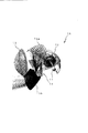
本発明の他の実施例として、図6、図7のように、副リフレクタのうち、第一の反射面15aを楕円系の自由曲面で形成し、第二の反射面15bを単純回転放物面で形成してもよい。
As another embodiment of the present invention, as shown in FIGS. 6 and 7, of the sub-reflectors, the first reflecting surface 15a is formed of an elliptical free-form surface, and the second reflecting
この場合、ロービーム時にシャッタ14で第二の反射面15bへの光を全て遮光するのではなく、一部(例えば放物面の焦点より前側)だけを遮光する。このようにすることで、車両用前照灯10は、ハイビームの配光パターンのおよそ下半分に相当する部分のみを前方に放射することになる。
In this case, not all the light to the second reflecting
そうすることで、車両用前照灯10は、図8のような配光パターンが投影レンズ部によるロービーム配光パターンに加算されることになり、ロービーム時の光量も上げることが可能になる。
By doing so, in the
また、本実施例において、開口部14cの形状はいかなる形状であってもよく、例えば所定形状の穴のようなものであったり、単に第二の反射面15bへの光路の一部を遮蔽するものであればよい。
In the present embodiment, the shape of the opening 14c may be any shape, for example, a hole having a predetermined shape, or simply shielding a part of the optical path to the second reflecting
本発明による車両前照灯10は、自動車用の前照灯として構成されているが、これに限らず、補助前照灯等を含む他の種類の車両用灯具に本発明を適用することが可能である。
The
このようにして、本発明によれば、簡単な構成により、配光パターンにおける中心付近の最大光度を高めると共に、照射光の全光束を増大させるようにした、極めて優れたバルブ横置き型のプロジェクタタイプ車両前照灯が提供され得る。 In this way, according to the present invention, a very good bulb horizontal projector that increases the maximum luminous intensity near the center of the light distribution pattern and increases the total luminous flux of the irradiated light with a simple configuration. A type vehicle headlamp may be provided.
10 車両用灯具
11 バルブ(光源バルブ)
11a 発光中心
12 主リフレクタ
13 投影レンズ
14 シャッタ
14a 上縁
14b 遮光部
14c 開口部
14d 回転軸
15 副リフレクタ
15a 第一の反射面
15b 第二の反射面
10
11a Light emission center 12
Claims (4)
この投影レンズの後側の焦点位置の後方にてほぼ光軸と直交する向きに配置された光源バルブと、
この光源バルブから出射する光を反射して上記投影レンズの照射方向後側の焦点位置付近に向かって集束する主リフレクタと、
この光源バルブから出射する光のうち前方やや上向きに出射する光を下方に反射する第一の反射面と、この第一の反射面からの光を照射方向前方の配光中心付近に向かって反射する第二の反射面とを有する副リフレクタと、
上記投影レンズの後側焦点位置付近に配置され当該投影レンズへの光路の少なくとも一部を遮蔽する第一の遮光部と、副リフレクタの上記第一の反射面から第二の反射面に反射される光路の少なくとも一部を遮蔽する第二の遮光部とを有するシャッタと、を備え、
上記シャッタが、
上記第一の遮光部が主リフレクタから投影レンズへの光路上にてすれ違いビーム用のカットオフを形成し上記第二の遮光部が副リフレクタの上記第一の反射面から第二の反射面に反射される光路の少なくとも一部を遮蔽する挿入位置と、上記投影レンズ及び副リフレクタの第二の反射面の光路を解放する退避位置との間で可動する車両用前照灯。 A convex projection lens disposed on an optical axis extending horizontally in the irradiation direction;
A light source bulb disposed in a direction substantially orthogonal to the optical axis behind the focal position on the rear side of the projection lens;
A main reflector that reflects the light emitted from the light source bulb and focuses the light toward the vicinity of the focal position on the rear side in the irradiation direction of the projection lens;
A first reflecting surface that reflects light emitted from the light source bulb forward and slightly upward is reflected downward, and light from the first reflecting surface is reflected toward the vicinity of the light distribution center forward in the irradiation direction. A secondary reflector having a second reflective surface
A first light-shielding portion that is disposed near the rear focal position of the projection lens and shields at least part of the optical path to the projection lens, and is reflected from the first reflecting surface of the sub-reflector to the second reflecting surface. A shutter having a second light-shielding portion that shields at least a part of the optical path to be
The shutter is
The first light-shielding part forms a cutoff for a passing beam on the optical path from the main reflector to the projection lens, and the second light-shielding part extends from the first reflecting surface to the second reflecting surface of the sub-reflector. A vehicular headlamp that is movable between an insertion position that shields at least a part of a reflected optical path and a retracted position that releases an optical path of a second reflecting surface of the projection lens and the sub-reflector.
挿入位置にあるときにはすれ違い配光を形成し、退避位置にあるときには走行用配光を形成する、請求項1に記載の車両用前照灯。 The shutter is
The vehicle headlamp according to claim 1, wherein a passing light distribution is formed when in the insertion position, and a traveling light distribution is formed when in the retracted position.
第二の遮光部の一部に開口部を有し、
上記第二の遮光部が、
挿入位置にあるときにはこの第二の遮光部によって副リフレクタの上記第一の反射面から第二の反射面に反射される光路の少なくとも一部を遮蔽し、退避位置にあるときには当該光路が上記開口部を通過する、請求項1に記載の車両用前照灯。 The shutter is
Having an opening in a part of the second light-shielding part;
The second light shielding part is
When in the insertion position, the second light-shielding portion shields at least part of the optical path reflected from the first reflecting surface to the second reflecting surface of the sub-reflector. The vehicle headlamp according to claim 1, which passes through the section.
挿入位置にあるときには上記第二の遮光部によって副リフレクタの上記第一の反射面から第二の反射面に反射される光路を遮蔽し上記投影レンズからのみ照射する、請求項1に記載の車両用前照灯。 The second light shielding part is
2. The vehicle according to claim 1, wherein when in the insertion position, the optical path reflected from the first reflecting surface of the sub-reflector to the second reflecting surface is shielded by the second light-shielding portion and irradiated only from the projection lens. For headlamps.
Priority Applications (1)
| Application Number | Priority Date | Filing Date | Title |
|---|---|---|---|
| JP2006013462A JP2007194166A (en) | 2006-01-23 | 2006-01-23 | Vehicular lamp |
Applications Claiming Priority (1)
| Application Number | Priority Date | Filing Date | Title |
|---|---|---|---|
| JP2006013462A JP2007194166A (en) | 2006-01-23 | 2006-01-23 | Vehicular lamp |
Publications (1)
| Publication Number | Publication Date |
|---|---|
| JP2007194166A true JP2007194166A (en) | 2007-08-02 |
Family
ID=38449687
Family Applications (1)
| Application Number | Title | Priority Date | Filing Date |
|---|---|---|---|
| JP2006013462A Pending JP2007194166A (en) | 2006-01-23 | 2006-01-23 | Vehicular lamp |
Country Status (1)
| Country | Link |
|---|---|
| JP (1) | JP2007194166A (en) |
Cited By (9)
| Publication number | Priority date | Publication date | Assignee | Title |
|---|---|---|---|---|
| JP2009259689A (en) * | 2008-04-18 | 2009-11-05 | Honda Motor Co Ltd | Vehicular headlight |
| JP2010153333A (en) * | 2008-12-26 | 2010-07-08 | Ichikoh Ind Ltd | Vehicle headlamp |
| JP2010165633A (en) * | 2009-01-19 | 2010-07-29 | Stanley Electric Co Ltd | Headlight unit for vehicle |
| JP2010232143A (en) * | 2009-03-30 | 2010-10-14 | Stanley Electric Co Ltd | Vehicular headlight unit |
| JP2012119339A (en) * | 2012-02-17 | 2012-06-21 | Stanley Electric Co Ltd | Vehicular lamp |
| CN103196087A (en) * | 2012-01-10 | 2013-07-10 | 株式会社小糸制作所 | Headlamp for vehicle |
| EP2551581A3 (en) * | 2011-07-26 | 2014-01-08 | Ichiko Industries, Ltd. | Vehicle Headlamp |
| US8864350B2 (en) | 2011-07-26 | 2014-10-21 | Ichikoh Industries, Ltd. | Vehicle headlamp |
| CN105240766A (en) * | 2015-10-30 | 2016-01-13 | 江苏亿诺车辆部件有限公司 | Projection unit structure for short-distance beams of automobile |
Citations (2)
| Publication number | Priority date | Publication date | Assignee | Title |
|---|---|---|---|---|
| JP2002324413A (en) * | 2001-04-24 | 2002-11-08 | Koito Mfg Co Ltd | Head light for vehicle |
| JP2005135918A (en) * | 2003-10-31 | 2005-05-26 | Valeo Vision | Vehicular headlamp with light source formed of discharge lamp |
-
2006
- 2006-01-23 JP JP2006013462A patent/JP2007194166A/en active Pending
Patent Citations (2)
| Publication number | Priority date | Publication date | Assignee | Title |
|---|---|---|---|---|
| JP2002324413A (en) * | 2001-04-24 | 2002-11-08 | Koito Mfg Co Ltd | Head light for vehicle |
| JP2005135918A (en) * | 2003-10-31 | 2005-05-26 | Valeo Vision | Vehicular headlamp with light source formed of discharge lamp |
Cited By (10)
| Publication number | Priority date | Publication date | Assignee | Title |
|---|---|---|---|---|
| JP2009259689A (en) * | 2008-04-18 | 2009-11-05 | Honda Motor Co Ltd | Vehicular headlight |
| JP2010153333A (en) * | 2008-12-26 | 2010-07-08 | Ichikoh Ind Ltd | Vehicle headlamp |
| JP2010165633A (en) * | 2009-01-19 | 2010-07-29 | Stanley Electric Co Ltd | Headlight unit for vehicle |
| JP2010232143A (en) * | 2009-03-30 | 2010-10-14 | Stanley Electric Co Ltd | Vehicular headlight unit |
| EP2551581A3 (en) * | 2011-07-26 | 2014-01-08 | Ichiko Industries, Ltd. | Vehicle Headlamp |
| US8864350B2 (en) | 2011-07-26 | 2014-10-21 | Ichikoh Industries, Ltd. | Vehicle headlamp |
| US9121562B2 (en) | 2011-07-26 | 2015-09-01 | Ichikoh Industries, Ltd. | Vehicle headlamp |
| CN103196087A (en) * | 2012-01-10 | 2013-07-10 | 株式会社小糸制作所 | Headlamp for vehicle |
| JP2012119339A (en) * | 2012-02-17 | 2012-06-21 | Stanley Electric Co Ltd | Vehicular lamp |
| CN105240766A (en) * | 2015-10-30 | 2016-01-13 | 江苏亿诺车辆部件有限公司 | Projection unit structure for short-distance beams of automobile |
Similar Documents
| Publication | Publication Date | Title |
|---|---|---|
| JP4669434B2 (en) | Vehicle headlamp | |
| US7350946B2 (en) | Vehicle headlamp | |
| JP5719671B2 (en) | Vehicle lighting | |
| US8419247B2 (en) | Vehicle light | |
| JP5442222B2 (en) | Vehicle headlamp | |
| JP2007194166A (en) | Vehicular lamp | |
| JP2008186773A (en) | Vehicle headlight | |
| JP4809635B2 (en) | Vehicle headlamp | |
| JP4422005B2 (en) | Vehicle headlamp | |
| JP4159953B2 (en) | Vehicle headlamp | |
| JP2006156045A (en) | Vehicular headlight | |
| JP2005228715A (en) | Vehicular head-light | |
| JP2008034182A (en) | Headlamp for vehicle | |
| JP2010040275A (en) | Vehicular headlamp | |
| JP2008135247A (en) | Vehicular headlight | |
| JP4758753B2 (en) | Vehicle headlamp | |
| JP4666266B2 (en) | Vehicle headlamp | |
| JP4608645B2 (en) | Vehicle lighting | |
| JP2007035332A (en) | Vehicular headlight | |
| JP5618312B2 (en) | Vehicle headlamp | |
| JP4960747B2 (en) | Vehicle headlamp | |
| JP5412314B2 (en) | Vehicle headlamp | |
| JP4189807B2 (en) | Vehicle lighting | |
| JP2006040785A (en) | Vehicular headlamp | |
| JP4587047B2 (en) | Vehicle lighting |
Legal Events
| Date | Code | Title | Description |
|---|---|---|---|
| A621 | Written request for application examination |
Free format text: JAPANESE INTERMEDIATE CODE: A621 Effective date: 20081225 |
|
| RD02 | Notification of acceptance of power of attorney |
Free format text: JAPANESE INTERMEDIATE CODE: A7422 Effective date: 20100621 |
|
| RD04 | Notification of resignation of power of attorney |
Free format text: JAPANESE INTERMEDIATE CODE: A7424 Effective date: 20100630 |
|
| A977 | Report on retrieval |
Free format text: JAPANESE INTERMEDIATE CODE: A971007 Effective date: 20101126 |
|
| A131 | Notification of reasons for refusal |
Free format text: JAPANESE INTERMEDIATE CODE: A131 Effective date: 20101130 |
|
| A521 | Written amendment |
Free format text: JAPANESE INTERMEDIATE CODE: A523 Effective date: 20110131 |
|
| A02 | Decision of refusal |
Free format text: JAPANESE INTERMEDIATE CODE: A02 Effective date: 20110322 |