JP2007170462A - Vehicle control device - Google Patents
Vehicle control device Download PDFInfo
- Publication number
- JP2007170462A JP2007170462A JP2005365864A JP2005365864A JP2007170462A JP 2007170462 A JP2007170462 A JP 2007170462A JP 2005365864 A JP2005365864 A JP 2005365864A JP 2005365864 A JP2005365864 A JP 2005365864A JP 2007170462 A JP2007170462 A JP 2007170462A
- Authority
- JP
- Japan
- Prior art keywords
- oil
- hydraulic
- pressure
- gear
- transmission
- Prior art date
- Legal status (The legal status is an assumption and is not a legal conclusion. Google has not performed a legal analysis and makes no representation as to the accuracy of the status listed.)
- Pending
Links
Images

Classifications
-
- F—MECHANICAL ENGINEERING; LIGHTING; HEATING; WEAPONS; BLASTING
- F16—ENGINEERING ELEMENTS AND UNITS; GENERAL MEASURES FOR PRODUCING AND MAINTAINING EFFECTIVE FUNCTIONING OF MACHINES OR INSTALLATIONS; THERMAL INSULATION IN GENERAL
- F16H—GEARING
- F16H57/00—General details of gearing
- F16H57/04—Features relating to lubrication or cooling or heating
- F16H57/0412—Cooling or heating; Control of temperature
- F16H57/0413—Controlled cooling or heating of lubricant; Temperature control therefor
-
- F—MECHANICAL ENGINEERING; LIGHTING; HEATING; WEAPONS; BLASTING
- F16—ENGINEERING ELEMENTS AND UNITS; GENERAL MEASURES FOR PRODUCING AND MAINTAINING EFFECTIVE FUNCTIONING OF MACHINES OR INSTALLATIONS; THERMAL INSULATION IN GENERAL
- F16H—GEARING
- F16H57/00—General details of gearing
- F16H57/04—Features relating to lubrication or cooling or heating
- F16H57/0434—Features relating to lubrication or cooling or heating relating to lubrication supply, e.g. pumps; Pressure control
Landscapes
- Engineering & Computer Science (AREA)
- General Engineering & Computer Science (AREA)
- Mechanical Engineering (AREA)
- Hybrid Electric Vehicles (AREA)
- General Details Of Gearings (AREA)
- Control Of Transmission Device (AREA)
Abstract
【課題】エンジン駆動のオイルポンプが停止状態になっても作動油の油温を適切に調整可能な車両用制御装置を提供する。
【解決手段】油圧を受けて変速作動する変速機2を有しエンジンENGの駆動力を駆動輪に伝達する動力伝達装置1と、エンジンにより駆動され変速機2に作動油を供給する第1オイルポンプP1と、電気モータにより駆動され変速機2に作動油を供給する第2オイルポンプP2と、第2オイルポンプP2から吐出された作動油の圧力を調整するリリーフバルブ86と、作動油の温度を調節する油温調整装置83とを有し、リリーフバルブ86の排出油路94を油温調整装置83に接続して車両用の制御装置70を構成する。
【選択図】図1A vehicle control device capable of appropriately adjusting the temperature of hydraulic oil even when an engine-driven oil pump is stopped.
A power transmission device (1) having a transmission (2) that receives a hydraulic pressure to perform a shift operation and transmitting a driving force of an engine (ENG) to driving wheels, and a first oil that is driven by the engine and supplies hydraulic oil to the transmission (2). A pump P1, a second oil pump P2 driven by an electric motor to supply hydraulic oil to the transmission 2, a relief valve 86 for adjusting the pressure of the hydraulic oil discharged from the second oil pump P2, and the temperature of the hydraulic oil And an oil temperature adjusting device 83 for adjusting the oil temperature adjusting device 83, and connecting the drain oil passage 94 of the relief valve 86 to the oil temperature adjusting device 83 to constitute a control device 70 for the vehicle.
[Selection] Figure 1
Description
本発明は、変速機を作動させる油圧供給源として、エンジンにより駆動されるオイルポンプと、電気モータにより駆動されるオイルポンプとを備えた車両用の制御装置に関する。 The present invention relates to a control device for a vehicle including an oil pump driven by an engine and an oil pump driven by an electric motor as a hydraulic pressure supply source for operating a transmission.
上記のようにエンジン駆動のオイルポンプと、電動モータ駆動のオイルポンプとを備えた車両としてハイブリッド車両がある。ハイブリッド車両の中には、変速機の車軸側(出力軸側)に駆動用モータを有し、エンジンを停止させた状態で駆動用モータにより走行可能なものがある。このようなハイブリッド車両では、エンジン駆動時において変速機に作動油を供給するエンジン駆動の第1オイルポンプと、電動モータ駆動の第2オイルポンプとを備え、エンジン停止状態からの再始動時等において、油圧供給源を選択的に切り替えて第2オイルポンプから変速機に作動油を供給するように構成した車両用制御装置が知られている(例えば、特許文献1を参照)。 As described above, there is a hybrid vehicle as a vehicle including the engine-driven oil pump and the electric motor-driven oil pump. Some hybrid vehicles have a drive motor on the axle side (output shaft side) of the transmission, and can be driven by the drive motor while the engine is stopped. Such a hybrid vehicle includes an engine-driven first oil pump that supplies hydraulic oil to the transmission when the engine is driven, and an electric motor-driven second oil pump. There is known a vehicle control device configured to selectively switch hydraulic pressure supply sources and supply hydraulic oil from a second oil pump to a transmission (see, for example, Patent Document 1).
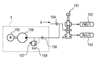
これを、変速機の前進クラッチと後進クラッチとに作動油を供給する場合について例示する図3に基づいて説明すると、151は作動油の供給先を前進クラッチ152と後進クラッチ153に切り替えるマニュアルバルブである。このマニュアルバルブ151には、エンジンにより駆動される第1の油圧供給源Xからの供給油路が第1の逆止弁154を介して接続され、この第1の逆止弁154の下流側にはエンジン停止時に第1の油圧供給源に代わってマニュアルバルブ151に作動油を供給する第2の油圧供給源Yが接続されている。第2の油圧供給源Yは電動モータ155により駆動されるオイルポンプ156を備え、オイルポンプ156からの供給油路が第2の逆止弁158を介して第1の逆止弁154の下流側に接続されている。オイルポンプ156と第2の逆止弁158との間には、オイルポンプ156から吐出された作動油の圧力を調整するリリーフバルブ157が設けられ、このリリーフバルブ157の排出油路がオイルパン159に接続されている。
This will be described with reference to FIG. 3 exemplifying the case where hydraulic oil is supplied to the forward clutch and the reverse clutch of the transmission. 151 is a manual valve that switches the hydraulic oil supply destination to the
また、第2の油圧供給源からの供給油路を、第1の油圧供給源の油圧を調整する調圧バルブに接続し、この調圧バルブを介して変速機に作動油を供給するように構成した制御装置が知られている(例えば、非特許文献1を参照)。 Further, the supply oil path from the second hydraulic pressure supply source is connected to a pressure regulating valve that adjusts the hydraulic pressure of the first hydraulic pressure supply source, and hydraulic oil is supplied to the transmission via the pressure regulating valve. A configured control device is known (for example, see Non-Patent Document 1).
しかしながら、上記図3に示すような従来の制御装置においては、車両が駆動用モータにより運転されている場合や、下り坂が連続して続きエンジンが停止した状態でありながら車両が高速で走行しているような場合に、上記第1の油圧供給源Xが停止状態となって作動油が冷却装置に供給されなくなり、油温上昇により変速機が冷却不足となる可能性があった。 However, in the conventional control device as shown in FIG. 3, the vehicle travels at a high speed while the vehicle is being driven by a drive motor, or the downhill is continuously continued and the engine is stopped. In such a case, there is a possibility that the first hydraulic pressure supply source X is stopped and hydraulic oil is not supplied to the cooling device, and the transmission is insufficiently cooled due to an increase in the oil temperature.
また、非特許文献1に開示された制御装置では、第2の油圧供給源が発生する油圧が、第1の油圧供給源の発生する油圧よりも低い場合に、調圧バルブを開弁させることができず、その結果冷却装置へ作動油を供給することができなくなって、同様に冷却不足を生じさせるおそれがあった。さらに、制御装置には、変速機の油温を早期に上昇させることによる燃費向上を目的としてオイルウォーマを設けたものがあるが、このような場合にも、従来ではエンジン停止状態において作動油がオイルウォーマに供給されないため、変速機油温の上昇が速やかに行われず、燃費向上効果が半減するという問題もあった。 In the control device disclosed in Non-Patent Document 1, when the hydraulic pressure generated by the second hydraulic supply source is lower than the hydraulic pressure generated by the first hydraulic supply source, the pressure regulating valve is opened. As a result, hydraulic oil could not be supplied to the cooling device, and there was a risk of insufficient cooling as well. In addition, some control devices are provided with an oil warmer for the purpose of improving fuel efficiency by raising the oil temperature of the transmission at an early stage. Since the oil temperature is not supplied to the oil warmer, the oil temperature of the transmission is not increased promptly, and the fuel efficiency improvement effect is halved.
本発明はこのような事情に鑑みてなされたものであり、エンジン駆動のオイルポンプが停止状態になっても作動油の油温を適切に調整可能な車両用制御装置を提供することを目的とする。 The present invention has been made in view of such circumstances, and an object thereof is to provide a vehicle control device capable of appropriately adjusting the oil temperature of hydraulic oil even when an engine-driven oil pump is stopped. To do.
上記目的を達成するため、本発明は、油圧を受けて変速作動する変速機を有しエンジンの駆動力を駆動輪に伝達する動力伝達装置と、エンジンにより駆動され変速機に作動油を供給する第1オイルポンプと、電気モータにより駆動され変速機に作動油を供給する第2オイルポンプと、第2オイルポンプから吐出された作動油の圧力を調整するリリーフバルブと、作動油の温度を調節する油温調整装置とを有し、リリーフバルブの排出油路を油温調整装置に接続して車両用制御装置を構成する。 In order to achieve the above object, the present invention includes a power transmission device that has a transmission that operates under a hydraulic pressure and transmits the driving force of the engine to drive wheels, and supplies hydraulic oil to the transmission that is driven by the engine. A first oil pump, a second oil pump driven by an electric motor to supply hydraulic oil to the transmission, a relief valve for adjusting the pressure of the hydraulic oil discharged from the second oil pump, and the temperature of the hydraulic oil is adjusted And an oil temperature adjusting device for connecting the drain oil passage of the relief valve to the oil temperature adjusting device to constitute a vehicle control device.
なお、第1オイルポンプから吐出された作動油の圧力を調整する調圧バルブを有し、調圧バルブの排出油路をリリーフバルブの排出油路に連結して油温調整装置に接続させるとともに、リリーフバルブの設定圧力を調圧バルブの設定圧力よりも低く設定して上記車両用制御装置を構成することが好ましい。 In addition, the pressure adjusting valve for adjusting the pressure of the hydraulic oil discharged from the first oil pump is provided, and the discharge oil passage of the pressure adjustment valve is connected to the discharge oil passage of the relief valve and connected to the oil temperature adjusting device. The vehicle control device is preferably configured by setting the set pressure of the relief valve lower than the set pressure of the pressure regulating valve.
本発明では、第2オイルポンプから吐出された作動油の圧力を調整するリリーフバルブの排出油路が油温調整装置に接続されており、リリーフバルブの圧力調整によって排出された余剰の作動油が油温調整装置により温度調整される。このため、例えば車両が駆動用モータにより運転されている場合や、下り坂が連続して続きエンジンが停止したアイドル停止状態でありながら車両が高速で走行している場合のように、エンジン駆動の第1オイルポンプが停止状態になっていても作動油が油温調整装置に送給されて温度調整され、変速機が冷却不足になるようなことがない。また油温調整装置がオイルウォーマの機能を有する場合には、エンジン停止状態であってもリリーフバルブから排出される余剰油がオイルウォーマに供給されて速やかに昇温されるため、変速機内部における作動油の攪拌抵抗が減少し、燃費向上効果をさらに高めることができる。 In the present invention, the discharge oil passage of the relief valve that adjusts the pressure of the hydraulic oil discharged from the second oil pump is connected to the oil temperature adjusting device, and excess hydraulic oil discharged by adjusting the pressure of the relief valve is discharged. The temperature is adjusted by an oil temperature adjusting device. For this reason, for example, when the vehicle is driven by a drive motor, or when the vehicle is traveling at a high speed while the engine is stopped in an idling stop state where the downhill continues continuously, Even when the first oil pump is in a stopped state, the hydraulic oil is supplied to the oil temperature adjusting device to adjust the temperature, and the transmission does not become insufficiently cooled. Further, when the oil temperature adjusting device has an oil warmer function, excess oil discharged from the relief valve is supplied to the oil warmer even when the engine is stopped, and the temperature is quickly raised. The stirring resistance of the hydraulic oil is reduced, and the fuel efficiency improvement effect can be further enhanced.
なお、第1オイルポンプから吐出された作動油の圧力を調整する調圧バルブの排出油路を上記リリーフバルブの排出油路に連結して油温調整装置に導くとともに、リリーフバルブの設定圧力を調圧バルブの設定圧力よりも低く設定した構成によれば、調圧バルブの開閉状態に拘わらず、第2オイルポンプの駆動時に作動油が油温調整装置に送給される。従って、例えば第1オイルポンプの吐出圧が、第2オイルポンプの吐出圧よりも高く、第2オイルポンプの発生した油圧で調圧バルブを開弁させることができないような場合であっても、リリーフバルブから排出された作動油が油温調整装置に送給されて温度調整され、変速機が冷却不足となるようなことがない。 In addition, the discharge oil passage of the pressure regulating valve for adjusting the pressure of the hydraulic oil discharged from the first oil pump is connected to the discharge oil passage of the relief valve to lead to the oil temperature adjusting device, and the set pressure of the relief valve is set. According to the configuration that is set lower than the set pressure of the pressure regulating valve, the hydraulic oil is supplied to the oil temperature adjusting device when the second oil pump is driven regardless of the open / closed state of the pressure regulating valve. Therefore, for example, even when the discharge pressure of the first oil pump is higher than the discharge pressure of the second oil pump and the pressure regulating valve cannot be opened by the hydraulic pressure generated by the second oil pump, The hydraulic oil discharged from the relief valve is fed to the oil temperature adjusting device to adjust the temperature, and the transmission does not become insufficiently cooled.
従って、本発明によれば、エンジン駆動のオイルポンプが停止状態になっても作動油の油温を適切に調整可能な車両用制御装置を提供することができる。 Therefore, according to the present invention, it is possible to provide a vehicle control device that can appropriately adjust the oil temperature of hydraulic oil even when the engine-driven oil pump is stopped.
以下、本発明を実施するための好ましい形態について図面を参照して説明する。図2に本発明に係る車両用制御装置が設けられた動力伝達装置1の概要構成を模式的に示している。この動力伝達装置1は、エンジンENGと、このエンジンの出力軸ESにトルクコンバータTCを介して連結された自動変速機(以下トランスミッションという)2と、トランスミッション2の車軸側に配設された第1駆動モータM1と、トランスミッション2とエンジンENGとの間に配設された第2駆動モータM2とから構成され、エンジンENGの回転駆動力を左右の駆動輪WL,WRに伝達して車両を走行させる。
Hereinafter, preferred embodiments for carrying out the present invention will be described with reference to the drawings. FIG. 2 schematically shows a schematic configuration of the power transmission device 1 provided with the vehicle control device according to the present invention. The power transmission device 1 includes an engine ENG, an automatic transmission (hereinafter referred to as a transmission) 2 connected to the engine output shaft ES via a torque converter TC, and a first shaft disposed on the axle side of the
第1駆動モータM1及び第2駆動モータM2は、電気モータ・ジェネレータであり、車載の図示省略するバッテリにより駆動されてエンジンENGの駆動力をアシストし、あるいはエンジンの停止時(休筒時)にモータの駆動力で走行することが可能であるとともに、エンジン走行時や減速走行時等に発電を行ってバッテリの充電を行うことができるようになっている。すなわち、動力伝達装置の駆動源は、エンジンENGとこれらの駆動モータM1,M2とからなり、ハイブリッド型になっている。 The first drive motor M1 and the second drive motor M2 are electric motors / generators that are driven by an in-vehicle battery (not shown) to assist the driving force of the engine ENG or when the engine is stopped (when the cylinder is idle). In addition to being able to travel with the driving force of the motor, it is possible to charge the battery by generating electricity during engine traveling, deceleration traveling, or the like. That is, the drive source of the power transmission device is composed of the engine ENG and the drive motors M1 and M2, and is of a hybrid type.
トランスミッション2は、後述する第1または第2オイルポンプにより発生された油圧を制御することで変速制御がなされる前進5速及び後進1速の平行軸式の変速機構であり、エンジンENGのクランクシャフトESにロックアップ機構LCを有するトルクコンバータTCを介して接続されたメインシャフト10と、このメインシャフト10と平行に延びて配設されるとともに、複数のギヤ列を介してメインシャフト10に接続されたセカンダリシャフト20、サードシャフト30、カウンタシャフト40を備え、図示省略するトランスミッションケースの内部に配設される。
The
メインシャフト10には、メイン3速ギヤ13が結合配設されるとともに、メイン4速ギヤ14、メイン5速ギヤ15、及びメイン5速ギヤ15と一体に連結されたメインリバースギヤ16が相対回転自在に配設されている。またメインシャフト10には、それぞれ相対回転自在に配設されたメイン4速ギヤ14をメインシャフト10に結合させる4速クラッチC4、メイン5速ギヤ15及びこれと一体のメインリバースギヤ16をメインシャフト10に結合させる5速クラッチC5が設けられている。
A main
セカンダリシャフト20には、セカンダリ1速ギヤ21及びセカンダリ2速ギヤ22が相対回転自在に配設され、セカンダリアイドルギヤ23が結合配設されている。またセカンダリシャフト20には、相対回転自在に配設されたセカンダリ1速ギヤ21をワンウェイクラッチ27を介してセカンダリシャフト20に結合させる1速クラッチC1、セカンダリ1速ギヤ21をワンウェイクラッチ27を介することなく直接セカンダリシャフト20に結合させる1速ホールドクラッチCL、及び相対回転自在に配設されたセカンダリ2速ギヤ22をセカンダリシャフト20に結合させる2速クラッチC2が設けられている。
A secondary
サードシャフト30には、メイン3速ギヤ13と噛合するサード3速ギヤ33が相対回転自在に配設され、メイン4速ギヤと噛合するサード4速ギヤ34が結合配設されるとともに、相対回転自在に配設されたサード3速ギヤ33をサードシャフトに結合させる3速クラッチC3が設けられている。
A third third-speed gear 33 that meshes with the main third-
カウンターシャフト40には、セカンダリ1速ギヤ21と噛合するカウンタ1速ギヤ41、セカンダリ2速ギヤ22と噛合するカウンタ2速ギヤ42、及びメイン4速ギヤ14と噛合するカウンタ4速ギヤ44が結合配設される。またカウンターシャフト40には、メイン3速ギヤ13及びセカンダリアイドルギヤ23と噛合するカウンタアイドルギヤ43、メイン5速ギヤ15と噛合するカウンタ5速ギヤ45、及びリバースアイドルギヤ36を介してメインリバースギヤ16と噛合するカウンタリバースギヤ46がそれぞれ相対回転自在に配設されている。
The
カウンターシャフト40上におけるカウンター5速ギヤ45とカウンターリバースギヤ46との間にドグ歯機構を利用したリバースセレクタ47が設けられており、そのセレクタスリーブ47aを図示省略するサーボアクチュエータで軸方向に移動させて、カウンタ5速ギヤ45をカウンタシャフト40に結合させ、あるいはカウンタリバースギヤ46をカウンタシャフト40に結合させることができるようになっている。
A
このように構成されたトランスミッション2において、1速クラッチC1を係合させてセカンダリ1速ギヤ21をセカンダリシャフト20に結合させると、メインシャフト10の回転がメイン3速ギヤ13、カウンタアイドルギヤ43、セカンダリアイドルギヤ23、セカンダリ1速ギヤ21、カウンタ1速ギヤ41からなる1速ギヤ列を介してカウンタシャフト40に伝達される1速段が設定される。1速クラッチC1を係合させた1速段では、セカンダリ1速ギヤ21がワンウェイクラッチ27を介してセカンダリシャフト20に結合されるため、アクセルをオフにしたときにワンウェイクラッチ27が滑り急減速しないようになっている。一方、1速ホールドクラッチCLを係合させた1速ホールド段ではギヤ列は同一であるが、セカンダリ1速ギヤ21がワンウェイクラッチ27を介することなく直接セカンダリシャフト20に結合されるため、強力なエンジンブレーキを作動させることができる。
In the
2速クラッチC2を係合させてセカンダリ2速ギヤ22をセカンダリシャフト20に結合させると、メインシャフト10の回転がメイン3速ギヤ13、カウンタアイドルギヤ43、セカンダリアイドルギヤ23、セカンダリ2速ギヤ22、及びカウンタ2速ギヤ42からなる2速ギヤ列を介してカウンタシャフト40に伝達される2速段が設定される。同様に、3速クラッチC3を係合させてサード3速ギヤ33をサードシャフト30に結合させると、メインシャフト10の回転がメイン3速ギヤ13、サード3速ギヤ33、サード4速ギヤ34、メイン4速ギヤ14、及びカウンタ4速ギヤ44からなる3速ギヤ列を介してカウンタシャフト40に伝達される3速段が設定される。また4速クラッチC4を係合させると、メインシャフト10の回転が、メイン4速ギヤ14とカウンタ4速ギヤ44とからなる4速ギヤ列を介してカウンタシャフト40に伝達される4速段が設定される。
When the second speed clutch C2 is engaged and the secondary
一方、5速クラッチC5を係合させて一体に形成されたメイン5速ギヤ15及びメインリバースギヤ16をメインシャフト10に結合させると、メインシャフト10の回転がこれらのギヤと噛合するカウンタ5速ギヤ45及びカウンタリバースギヤ46に伝達される。但し、カウンタ5速ギヤ45及びカウンタリバースギヤ46はそれぞれカウンタシャフト40に相対回転自在に配設されており、リバースセレクタ47の作動に応じてカウンタシャフト40と選択的に係脱される。
On the other hand, when the main 5-speed gear 15 and the
すなわち、図示省略するサーボアクチュエータによりセレクタスリーブ47aを図2における右方に移動させてカウンタ5速ギヤ45をカウンタシャフト40に結合させると、メインシャフト10の回転がメイン5速ギヤ15及びカウンタ5速ギヤ45からなる5速ギヤ列を介してカウンタシャフト40に伝達される5速段が設定される。一方、セレクタスリーブ47aを図2における左方に移動させてカウンタリバースギヤ46をカウンタシャフト40に結合させると、メインシャフト10の回転がメインリバースギヤ16、リバースアイドルギヤ36、及びカウンタリバースギヤ46からなるリバースギヤ列を介してカウンタシャフト40に伝達されるリバース段が設定される。
That is, when the selector sleeve 47a is moved rightward in FIG. 2 by a servo actuator (not shown) and the counter 5-
以上のように、1速、2速、3速、4速、5速クラッチC1〜C5及び1速ホールドクラッチCLの係合制御と、サーボアクチュエータによるリバースセレクタ27のセレクタスリーブ27aの移動制御とにより1速〜5速、1速ホールド、及びリバース段の設定がなされる。これら1速〜5速クラッチC1〜C5及び1速ホールドクラッチCLの係合制御と、サーボアクチュエータの作動制御、及びトランスミッション各部の潤滑が、油圧制御装置7から供給される作動油により行われる。油圧制御装置7の作動制御はコントロールユニットECUからの制御信号に基づいて行われる。
As described above, by the engagement control of the 1st speed, 2nd speed, 3rd speed, 4th speed, 5th speed clutch C1 to C5 and 1st speed hold clutch CL and the movement control of the selector sleeve 27a of the
以上のようにして1速段〜5速段、1速ホールド段、及びリバース段が設定され、各ギヤ列を介してメインシャフト10の回転がカウンタシャフト40に伝達される。カウンタシャフト40の回転は、このカウンタシャフト40に結合配設されたファイナルドライブギヤ48、及びファイナルドライブギヤ48と噛合するファイナルドリブンギヤ58を介してディファレンシャル機構DFに伝達され、左右のアクスルシャフト59,59を介して左右の駆動輪WL,WRに伝達される。
As described above, the first gear to the fifth gear, the first gear hold step, and the reverse gear are set, and the rotation of the
また、トランスミッション2の車軸側には、第1駆動モータM1の回転駆動力を駆動輪に伝達するモータ動力伝達機構5が配設されている。モータ動力伝達機構5は、第1駆動モータM1のスピンドルに結合配設されたモータ駆動ギヤ51、モータ駆動ギヤ51と噛合するモータアイドラギヤ52、モータカウンタシャフト50に回転自在に配設されたモータ従動ギヤ53、モータカウンタシャフト50に結合配設されたモータファイナルドライブギヤ54、及びシンクロクラッチ57から構成される。
A motor
シンクロクラッチ57は、詳細図示しないサーボアクチュエータによりシンクロスリーブ57aを軸方向に移動させて、モータ従動ギヤ53をモータカウンタシャフト50に結合させ、あるいはモータ従動ギヤ53とモータカウンタシャフト50との結合を切り離すことができるようになっている。このため、シンクロクラッチ57が係合されると、第1駆動モータM1の回転がモータ駆動ギヤ51、モータアイドラギヤ52、モータ従動ギヤ53、モータファイナルドライブギヤ54からなるモータギヤ列を介して、モータファイナルドライブギヤ54と噛合するファイナルドリブンギヤ58を介してディファレンシャル機構DFに伝達され、左右のアクスルシャフト59,59を介して左右の駆動輪WL,WRに伝達される。
The synchro clutch 57 moves the
従って、このハイブリッド車両では、第2駆動モータM2をエンジンENGのスタータとして使用しアイドル停止状態(休筒状態)のエンジンを始動させることができ、エンジンENGの駆動時にはエンジン駆動力をアシストさせてトランスミッション2において設定された速度段で車両を走行させることができる。またエンジンENGを停止させ、1速〜5速クラッチC1〜C5及び1速ホールドクラッチCLの係合を解除した状態で、モータ動力伝達装置5のシンクロクラッチ57を係合させ、第1駆動モータM1により走行が可能になっている。シンクロクラッチ57のサーボアクチュエータの作動制御、およびモータ動力伝達装置5の各部の潤滑も、トランスミッション2と同様に油圧制御装置7から供給される作動油により行われる。
Therefore, in this hybrid vehicle, the engine in the idling stop state (cylinderless state) can be started using the second drive motor M2 as a starter of the engine ENG, and the engine driving force is assisted to drive the engine ENG. The vehicle can be driven at the speed stage set in 2. Further, the engine ENG is stopped, and the first-speed to fifth-speed clutches C1 to C5 and the first-speed hold clutch CL are disengaged, and the
油圧制御装置7は、トルクコンバータTCの入力軸側に設けられエンジンENGにより回転駆動される第1オイルポンプP1、図示省略するバッテリの電力を利用して電動モータにより回転駆動される第2オイルポンプP2、及びこれらのオイルポンプP1,P2から吐出された作動油を各油圧アクチュエータ(C1〜C5、CL、リバースセレクタ27及びシンクロクラッチ57のサーボアクチュエータ等)やアリング等の潤滑部位に導くための複数の油圧制御バルブ、及びこれらの間を繋ぐ油路からなり、第2オイルポンプP2、各油圧制御バルブの作動がコントロールユニットECUにより制御される。
The
コントロールユニットECUには、運転席に設けられたシフトレバー装置において運転者が選択したシフトポジションの選択信号やスロットル開度の信号、車両の走行速度や傾斜角度等の走行状態を検出する検出信号が入力されており、コントロールユニットECUは、これらの信号に基づいた制御信号を油圧制御装置7に出力して1速〜5速クラッチC1〜C5等の作動を制御し、第1駆動モータM1、第2駆動モータM2に制御信号を出力して各駆動モータの作動を制御する。これによりトランスミッション2が選択されたシフトポジションに応じて自動変速されるとともに、第1,第2駆動モータM1,M2を利用した駆動力アシストやモータ走行、バッテリの充電が行われる。
The control unit ECU has a detection signal for detecting a traveling state such as a shift position selection signal, a throttle opening signal, a vehicle traveling speed or an inclination angle selected by the driver in a shift lever device provided in the driver's seat. The control unit ECU outputs control signals based on these signals to the
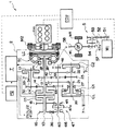
さて、以上のように概要構成される動力伝達装置1において、油圧制御装置7に本発明に係る制御装置70が適用されている。図1に油圧制御装置7における本発明の要部の油圧回路図を示している。
Now, in the power transmission device 1 schematically configured as described above, the control device 70 according to the present invention is applied to the
制御装置70は、ストレーナが設けられたオイルパン71、オイルパン71と第1オイルポンプP1の吸入口とを繋ぐ第1吸入油路72、第1オイルポンプP1の吐出口と調圧バルブ81とを繋ぎ、第1オイルポンプP1から吐出された作動油を調圧バルブ81の二箇所の入力ポート81a,81bに導く第1吐出油路73、オイルパン71と第2オイルポンプP2の吸入口とを繋ぐ第2吸入油路74、第2オイルポンプP2の吐出口と第1吐出油路73とを繋ぎ第2オイルポンプP2から吐出された作動油を第1吐出油路73に合流させて調圧バルブ81に導く第2吐出油路75、第2吐出油路75に設けられて第1吐出油路73側から第2吐出油路75側への作動油の流れを規制する逆止弁76、第1吐出油路72から分岐して油圧アクチュエータ(C1〜C5、CL、リバースセレクタ27及びシンクロクラッチ57のサーボアクチュエータ等)の制御油圧回路に繋がるライン圧供給油路77、調圧バルブ81の第2出力ポート81dとトランスミッション各部の潤滑部位に繋がる潤滑圧供給油路78を有して構成されている。
The control device 70 includes an
また、調圧バルブ81の第1出力ポート81cは、トルクコンバータTCの制御油圧回路82を介して油温調整装置83の入口側に繋がる第1排出油路91が接続され、油温調整装置83の出口側とオイルパン71との間を繋いで戻り油路92が設けられている。なお、戻り油路92にオイルフィルタ84、第1排出油路91にクーラチェックバルブ85が設けられている。
Further, the first output port 81c of the
ここで、調圧バルブ81は、バルブボディと、バルブボディの内部に軸方向に摺動自在に配設されたスプールと、このスプールを図1における左方に付勢するスプリングとを備え、二つの入力ポート(第1入力ポート81a、第2入力ポート81b)と、これに対応した二つの出力ポート(第1出力ポート81c、第2出力ポート81d)とを有して構成されるレギュレータバルブである。スプールには、第1入力ポート81aのスプール溝と、スプール軸端のピストン室との間を繋ぐ内部油路が形成されており、第1入力ポート81aを介してピストン室に作用する油圧によりスプールを図1における右方に摺動させ、この油圧による付勢力とスプリングの付勢力とのバランスにより弁開度を調整して、第1吐出油路73の油圧及びこの第1吐出油路から分岐するライン圧供給油路77の油圧(ライン圧)を調圧する。調圧バルブ81の設定圧は、例えば9.5kgf/cm2程度に設定される。
Here, the
油温調整装置83は、エンジンの冷却水と熱交換を行う水:オイルの熱交換機であり、エンジン始動時にはエンジン冷却水の方が作動油よりも早期に温度上昇するため、作動油を暖めるオイルウォーマとして機能する。一方、通常走行時においては、大容量のラジエタ及びサーモスタット等からなる冷却回路によってエンジン冷却水が略一定温度に温度管理されるため、高温になった作動油を冷却するオイルクーラとして機能する。すなわち、油温調整装置83は、オイルクーラとオイルウォーマの両方の機能を併せ持ったオイルクーラ/ウォーマである。
The oil
そして、第2吐出油路75から分岐してリリーフバルブ86に繋がる第2分岐油路93が設けられ、リリーフバルブ86の排出ポートと油温調整装置83との間を繋いで第2排出油路94が設けられている。リリーフバルブ86の設定圧は、調圧バルブ81の設定圧よりも低い圧力、例えば3kgf/cm2程度に設定され、第2吐出油路75の油圧がこの設定圧以上になったときに開弁して第2吐出油路75の圧力を調整し、余剰となった作動油が第2排出油路94及び戻り油路92を介してオイルパン71に戻されるようになっている。なお、第1排出油路91、第2排出油路94及び戻り油路92(油温調整装置83、フィルタ84)を通ってオイルパン71に戻る回路はリサーキュ回路と呼ばれる。
A second
このような構成の制御装置70では、エンジンENGが駆動し第1オイルポンプP1が作動しているときは、オイルパン71に貯留された作動油が第1吸入油路72を通って第1オイルポンプP1に吸い込まれ、この第1オイルポンプP1により加圧されて吐出された作動油が、第1吐出油路73を通って調圧バルブ81の第1及び第2入力ポート81a、81bに供給される。これらの入力ポートに供給された作動油は、前述した調圧バルブ81の圧力調整機能により調圧され、入力ポートに繋がる第1吐出油路73及びライン圧供給油路77の油圧が前記所定のライン圧に調整されて、ライン圧供給油路77を通って各油圧アクチュエータの制御油圧回路に供給される。また調圧バルブ81の調圧作動に伴い第2出力ポート81dに排出された作動油が潤滑圧供給油路78を通ってトランスミッション各部の潤滑部位に供給され、第1出力ポート81cに排出された作動油がトルクコンバータの制御油圧回路82を介して油温調整装置83に供給され、油温が調整されたのち戻り油路92を通ってオイルパン71に戻される。
In the control device 70 having such a configuration, when the engine ENG is driven and the first oil pump P1 is operating, the hydraulic oil stored in the
一方、例えばアイドル停止制御によりエンジンENGが停止し、これに伴って第1オイルポンプP1の作動が停止したときには、コントロールユニットECUにより第2オイルポンプP2の電動モータが回転駆動され第2オイルポンプP2が作動する。第2オイルポンプP2が作動すると、オイルパン71に貯留された作動油が第2吸入油路74を通って第2オイルポンプP2に吸い込まれ、第2オイルポンプP2により加圧されて第2吐出油路75に吐出される。第2吐出油路75吐出された作動油は、この油路に設けられた逆止弁76を開弁させ、合流する第1吐出油路73を通って調圧バルブ81の第1及び第2入力ポート81a、81bに供給され、ライン圧供給油路77を通って各油圧アクチュエータの制御油圧回路に供給される。
On the other hand, for example, when the engine ENG is stopped by idle stop control and the operation of the first oil pump P1 is stopped accordingly, the electric motor of the second oil pump P2 is rotationally driven by the control unit ECU, and the second oil pump P2 is driven. Operates. When the second oil pump P2 is operated, the hydraulic oil stored in the
また入力ポートに供給される油圧が調圧弁81の設定圧以上となったときには、前述同様にライン圧に調整された作動油がライン圧供給油路77に供給され、また調圧バルブ81の調圧作動により第1出力ポート81c及び第2出力ポート81dに排出された作動油が潤滑圧供給油路78を通ってトランスミッション各部の潤滑部位及びトルクコンバータの制御油圧回路82に供給される。このように、エンジンENGが停止したアイドル停止状態であっても第2オイルポンプP2により発生された油圧がライン圧供給油路77を通って油圧アクチュエータの制御油圧回路に供給されるため、エンジンENGの再始動時における油圧の立ち上がり遅れを防止し、発進応答遅れを防止することができる。
When the hydraulic pressure supplied to the input port becomes equal to or higher than the set pressure of the
一方、第2吐出油路75吐出された作動油は、第2吐出油路75から分岐する第2分岐油路93を通ってリリーフバルブ86に導かれ、このリリーフバルブ86の排出ポートが第2排出油路94により油温調整装置83に接続されている。このため、第2吐出油路75の油圧がリリーフバルブ86の設定圧以上になるとバルブが開弁し、第2排出油路94に排出された作動油が油温調整装置83を通り、油温調整装置83により温度調整されてオイルパン71に戻される。
On the other hand, the hydraulic oil discharged from the second
このため、変速クラッチC1〜C5,CLがすべて切り離され、車両が第1駆動モータM1の駆動力だけで運転されている場合や、下り坂が連続して続きエンジンENGがアイドル停止状態でありながら車両が高速で走行している場合のように、エンジン駆動の第1オイルポンプP1が停止状態になっていても、リリーフバルブ86から排出された作動油が油温調整装置83に送給されて温度調整され、トランスミッション2が冷却不足になるようなことがない。また油温調整装置83がオイルウォーマの機能をも有しているため、リリーフバルブ86から排出された作動油が油温調整装置83で速やかに昇温され、トランスミッション内部における作動油の攪拌抵抗を減少させて、燃費向上効果を高めることができる。
For this reason, when all the transmission clutches C1 to C5 and CL are disconnected and the vehicle is driven only by the driving force of the first drive motor M1, downhills continue continuously while the engine ENG is in an idle stop state. Even when the engine-driven first oil pump P1 is stopped as in the case where the vehicle is traveling at high speed, the hydraulic oil discharged from the
また、リリーフバルブ86の設定圧力を調圧バルブ81の設定圧力よりも低く設定しているため、調圧バルブ81の開閉状態に拘わらず、すなわち第1排出油路91を通る作動油の有無や流量に依存することなく、作動油が確実に油温調整装置83に送給され温度調整される。従って、第1オイルポンプP1の吐出圧が第2オイルポンプP2の吐出圧よりも高く、第2オイルポンプP2の発生した油圧で調圧バルブ81を開弁させることができない場合であっても、リリーフバルブ86から排出された作動油が確実に油温調整装置83に送給されて温度調整され、トランスミッション2が冷却不足となるようなことがない。特に、ハイブリッド車両に用いられる第2オイルポンプP2は、省燃費を目的とするアイドル停止制御時において、電力消費量を抑制しつつトランスミッション2の機能を維持するために必要最小限の油圧を確保することが求められる。本構成によれば調圧バルブ81を開弁させ得るような高吐出圧の電動オイルポンプを用いる必要がなく、電力消費量を抑制した小型の電動オイルポンプを用いて冷却不足を生じない制御装置を構成することができる。
Further, since the set pressure of the
さらに、制御装置70では、油温調整装置83としてオイルウォーマの機能をも有する熱交換器を用いており、作動油が低温の場合にはリリーフバルブ86から排出された作動油が油温調整装置83で速やかに昇温される。このため、作動油の粘性抵抗が早期に低下してトランスミッション内部における作動油の攪拌抵抗が低減され、車両の燃費向上効果をさらに高めることができる。
Further, in the control device 70, a heat exchanger having an oil warmer function is used as the oil
従って、以上説明した本発明の制御装置70によれば、エンジン駆動の第1オイルポンプP1が停止状態になっても作動油の油温を適切に調整可能な車両用制御装置を提供することができる。 Therefore, according to the control device 70 of the present invention described above, it is possible to provide a vehicle control device capable of appropriately adjusting the oil temperature of the hydraulic oil even when the engine-driven first oil pump P1 is stopped. it can.
ENG エンジン
P1 第1オイルポンプ
P2 第2オイルポンプ
1 動力伝達装置
2 トランスミッション(変速機)
70 制御装置
81 調圧バルブ
83 油温調整装置
86 リリーフバルブ
91 第1排出油路(調圧バルブの排出油路)
94 第2排出油路(リリーフバルブの排出油路)
ENG engine P1 first oil pump P2 second oil pump 1
70
94 Second oil discharge passage (Relief valve discharge oil passage)
Claims (2)
前記エンジンにより駆動され前記変速機に作動油を供給する第1オイルポンプと、
電気モータにより駆動され前記変速機に作動油を供給する第2オイルポンプと、
前記第2オイルポンプから吐出された作動油の圧力を調整するリリーフバルブと、
前記作動油の温度を調節する油温調整装置とを有し、
前記リリーフバルブの排出油路を前記油温調整装置に接続したこと
を特徴とする車両用制御装置。 A power transmission device that has a transmission that receives a hydraulic pressure and performs a shift operation, and that transmits the driving force of the engine to driving wheels;
A first oil pump driven by the engine to supply hydraulic oil to the transmission;
A second oil pump driven by an electric motor to supply hydraulic oil to the transmission;
A relief valve for adjusting the pressure of the hydraulic oil discharged from the second oil pump;
An oil temperature adjusting device for adjusting the temperature of the hydraulic oil,
A vehicle control device, wherein the oil discharge passage of the relief valve is connected to the oil temperature adjusting device.
前記調圧バルブの排出油路を前記リリーフバルブの排出油路に連結して前記油温調整装置に接続させるとともに、
前記リリーフバルブの設定圧力を前記調圧バルブの設定圧力よりも低く設定したことを特徴とする請求項1に記載の車両用制御装置。
A pressure regulating valve for adjusting the pressure of the hydraulic oil discharged from the first oil pump;
The discharge oil passage of the pressure regulating valve is connected to the discharge oil passage of the relief valve and connected to the oil temperature adjusting device,
2. The vehicle control device according to claim 1, wherein a set pressure of the relief valve is set lower than a set pressure of the pressure regulating valve.
Priority Applications (1)
| Application Number | Priority Date | Filing Date | Title |
|---|---|---|---|
| JP2005365864A JP2007170462A (en) | 2005-12-20 | 2005-12-20 | Vehicle control device |
Applications Claiming Priority (1)
| Application Number | Priority Date | Filing Date | Title |
|---|---|---|---|
| JP2005365864A JP2007170462A (en) | 2005-12-20 | 2005-12-20 | Vehicle control device |
Publications (1)
| Publication Number | Publication Date |
|---|---|
| JP2007170462A true JP2007170462A (en) | 2007-07-05 |
Family
ID=38297287
Family Applications (1)
| Application Number | Title | Priority Date | Filing Date |
|---|---|---|---|
| JP2005365864A Pending JP2007170462A (en) | 2005-12-20 | 2005-12-20 | Vehicle control device |
Country Status (1)
| Country | Link |
|---|---|
| JP (1) | JP2007170462A (en) |
Cited By (9)
| Publication number | Priority date | Publication date | Assignee | Title |
|---|---|---|---|---|
| JP2009204067A (en) * | 2008-02-27 | 2009-09-10 | Mazda Motor Corp | Hydraulic control device for automatic transmission |
| JP2010236693A (en) * | 2009-03-09 | 2010-10-21 | Toyota Motor Corp | Hydraulic control device for automatic transmission |
| WO2010127740A1 (en) | 2009-05-05 | 2010-11-11 | Daimler Ag | Drive train device |
| EP2277754A4 (en) * | 2008-04-17 | 2011-07-20 | Aisin Ai Co Ltd | CONTROL SYSTEM FOR HYBRID POWER UNIT |
| CN103216444A (en) * | 2012-01-23 | 2013-07-24 | 本田技研工业株式会社 | An operation state switching device of a pump with variable capacity |
| CN106286790A (en) * | 2016-09-21 | 2017-01-04 | 江苏大学 | A kind of combined radiating device and method for wind-power electricity generation reduction gear box |
| US9702381B2 (en) | 2013-10-28 | 2017-07-11 | Toyota Jidosha Kabushiki Kaisha | Hydraulic control system |
| US9897199B2 (en) | 2013-10-04 | 2018-02-20 | Toyota Jidosha Kabushiki Kaisha | Hydraulic circuit for power transmission device of vehicle |
| DE102009041236B4 (en) | 2009-09-11 | 2018-08-16 | Daimler Ag | A power train assembly |
-
2005
- 2005-12-20 JP JP2005365864A patent/JP2007170462A/en active Pending
Cited By (11)
| Publication number | Priority date | Publication date | Assignee | Title |
|---|---|---|---|---|
| JP2009204067A (en) * | 2008-02-27 | 2009-09-10 | Mazda Motor Corp | Hydraulic control device for automatic transmission |
| EP2277754A4 (en) * | 2008-04-17 | 2011-07-20 | Aisin Ai Co Ltd | CONTROL SYSTEM FOR HYBRID POWER UNIT |
| JP2010236693A (en) * | 2009-03-09 | 2010-10-21 | Toyota Motor Corp | Hydraulic control device for automatic transmission |
| WO2010127740A1 (en) | 2009-05-05 | 2010-11-11 | Daimler Ag | Drive train device |
| US8955316B2 (en) | 2009-05-05 | 2015-02-17 | Daimler Ag | Drive train device |
| DE102009041236B4 (en) | 2009-09-11 | 2018-08-16 | Daimler Ag | A power train assembly |
| CN103216444A (en) * | 2012-01-23 | 2013-07-24 | 本田技研工业株式会社 | An operation state switching device of a pump with variable capacity |
| CN103216444B (en) * | 2012-01-23 | 2016-01-20 | 本田技研工业株式会社 | The operating condition COMM communication of variable displacement pump |
| US9897199B2 (en) | 2013-10-04 | 2018-02-20 | Toyota Jidosha Kabushiki Kaisha | Hydraulic circuit for power transmission device of vehicle |
| US9702381B2 (en) | 2013-10-28 | 2017-07-11 | Toyota Jidosha Kabushiki Kaisha | Hydraulic control system |
| CN106286790A (en) * | 2016-09-21 | 2017-01-04 | 江苏大学 | A kind of combined radiating device and method for wind-power electricity generation reduction gear box |
Similar Documents
| Publication | Publication Date | Title |
|---|---|---|
| US8413437B2 (en) | Transmission hydraulic control system having independently controlled stator cooling flow | |
| CN101147014B (en) | Method and apparatus for controlling oil supply to automatic transmission and starter | |
| US8784249B2 (en) | Automatic transmission for hybrid vehicle | |
| CN102165222B (en) | Power transmission device and vehicle equipped with the power transmission device | |
| JP6036277B2 (en) | Vehicle transmission | |
| JP6048576B2 (en) | Oil supply device | |
| US8042331B2 (en) | On-demand hydraulic pump for a transmission and method of operation | |
| JP5445045B2 (en) | Hydraulic control device for automatic transmission | |
| CN102422059B (en) | Hydraulic controls for automatic transmissions | |
| CN107097628B (en) | Hybrid powertrain and its hydraulic control system | |
| CN101946105A (en) | Dual clutch transmission having area controlled clutch cooling circuit | |
| JP4707585B2 (en) | Vehicle control device | |
| CN106256588A (en) | Control device for power-transmission system | |
| CN106499814A (en) | Hydraulic control system for a multi-mode electro-mechanical drive unit of an automatic transmission | |
| JP4754962B2 (en) | Lubricator for vehicles | |
| CN108779851B (en) | Oil pressure control device | |
| JP4530999B2 (en) | Control device for hybrid vehicle | |
| JP2007216865A (en) | Power transmission device for hybrid vehicle | |
| CN101779056A (en) | Stepped automatic transmission and vehicle equipped with same | |
| JP2013217492A (en) | Hydraulic pressure supply device of automatic transmission | |
| JP4833675B2 (en) | Hydraulic control device for automatic transmission | |
| JP4610493B2 (en) | Hydraulic control valve | |
| JP2007078011A (en) | Hydraulic adjustment device for automatic transmission | |
| JP2009097677A (en) | Control device for variable displacement fluid pressure pump motor type transmission | |
| CN111601989A (en) | Drive train for a motor vehicle and method for starting an internal combustion engine in such a drive train |