JP2007163055A - Heat exchanger with receiver tank - Google Patents
Heat exchanger with receiver tank Download PDFInfo
- Publication number
- JP2007163055A JP2007163055A JP2005361465A JP2005361465A JP2007163055A JP 2007163055 A JP2007163055 A JP 2007163055A JP 2005361465 A JP2005361465 A JP 2005361465A JP 2005361465 A JP2005361465 A JP 2005361465A JP 2007163055 A JP2007163055 A JP 2007163055A
- Authority
- JP
- Japan
- Prior art keywords
- receiver tank
- heat exchanger
- header
- divided
- headers
- Prior art date
- Legal status (The legal status is an assumption and is not a legal conclusion. Google has not performed a legal analysis and makes no representation as to the accuracy of the status listed.)
- Pending
Links
Images


Classifications
-
- F—MECHANICAL ENGINEERING; LIGHTING; HEATING; WEAPONS; BLASTING
- F25—REFRIGERATION OR COOLING; COMBINED HEATING AND REFRIGERATION SYSTEMS; HEAT PUMP SYSTEMS; MANUFACTURE OR STORAGE OF ICE; LIQUEFACTION SOLIDIFICATION OF GASES
- F25B—REFRIGERATION MACHINES, PLANTS OR SYSTEMS; COMBINED HEATING AND REFRIGERATION SYSTEMS; HEAT PUMP SYSTEMS
- F25B39/00—Evaporators; Condensers
- F25B39/04—Condensers
-
- F—MECHANICAL ENGINEERING; LIGHTING; HEATING; WEAPONS; BLASTING
- F28—HEAT EXCHANGE IN GENERAL
- F28F—DETAILS OF HEAT-EXCHANGE AND HEAT-TRANSFER APPARATUS, OF GENERAL APPLICATION
- F28F9/00—Casings; Header boxes; Auxiliary supports for elements; Auxiliary members within casings
- F28F9/02—Header boxes; End plates
- F28F9/0246—Arrangements for connecting header boxes with flow lines
-
- F—MECHANICAL ENGINEERING; LIGHTING; HEATING; WEAPONS; BLASTING
- F25—REFRIGERATION OR COOLING; COMBINED HEATING AND REFRIGERATION SYSTEMS; HEAT PUMP SYSTEMS; MANUFACTURE OR STORAGE OF ICE; LIQUEFACTION SOLIDIFICATION OF GASES
- F25B—REFRIGERATION MACHINES, PLANTS OR SYSTEMS; COMBINED HEATING AND REFRIGERATION SYSTEMS; HEAT PUMP SYSTEMS
- F25B2339/00—Details of evaporators; Details of condensers
- F25B2339/04—Details of condensers
- F25B2339/044—Condensers with an integrated receiver
- F25B2339/0446—Condensers with an integrated receiver characterised by the refrigerant tubes connecting the header of the condenser to the receiver; Inlet or outlet connections to receiver
-
- F—MECHANICAL ENGINEERING; LIGHTING; HEATING; WEAPONS; BLASTING
- F25—REFRIGERATION OR COOLING; COMBINED HEATING AND REFRIGERATION SYSTEMS; HEAT PUMP SYSTEMS; MANUFACTURE OR STORAGE OF ICE; LIQUEFACTION SOLIDIFICATION OF GASES
- F25B—REFRIGERATION MACHINES, PLANTS OR SYSTEMS; COMBINED HEATING AND REFRIGERATION SYSTEMS; HEAT PUMP SYSTEMS
- F25B40/00—Subcoolers, desuperheaters or superheaters
- F25B40/02—Subcoolers
-
- F—MECHANICAL ENGINEERING; LIGHTING; HEATING; WEAPONS; BLASTING
- F28—HEAT EXCHANGE IN GENERAL
- F28F—DETAILS OF HEAT-EXCHANGE AND HEAT-TRANSFER APPARATUS, OF GENERAL APPLICATION
- F28F9/00—Casings; Header boxes; Auxiliary supports for elements; Auxiliary members within casings
- F28F9/02—Header boxes; End plates
- F28F9/0202—Header boxes having their inner space divided by partitions
- F28F9/0204—Header boxes having their inner space divided by partitions for elongated header box, e.g. with transversal and longitudinal partitions
- F28F9/0209—Header boxes having their inner space divided by partitions for elongated header box, e.g. with transversal and longitudinal partitions having only transversal partitions
- F28F9/0212—Header boxes having their inner space divided by partitions for elongated header box, e.g. with transversal and longitudinal partitions having only transversal partitions the partitions being separate elements attached to header boxes
-
- F—MECHANICAL ENGINEERING; LIGHTING; HEATING; WEAPONS; BLASTING
- F28—HEAT EXCHANGE IN GENERAL
- F28F—DETAILS OF HEAT-EXCHANGE AND HEAT-TRANSFER APPARATUS, OF GENERAL APPLICATION
- F28F9/00—Casings; Header boxes; Auxiliary supports for elements; Auxiliary members within casings
- F28F9/02—Header boxes; End plates
- F28F9/0219—Arrangements for sealing end plates into casing or header box; Header box sub-elements
- F28F9/0224—Header boxes formed by sealing end plates into covers
Abstract
Description
本発明は、レシーバタンク付き熱交換器に関する。 The present invention relates to a heat exchanger with a receiver tank.
従来、一対のヘッダ間に、両端を両ヘッダに連通接続されるチューブが複数配置され、両ヘッダの内部が仕切り板で仕切られて凝縮部と過冷却部に区分される熱交換器本体と、前記熱交換器本体の一方のヘッダの凝縮部と過冷却部に結合部材を介して連通接続されるレシーバタンクを備えるレシーバタンク付き熱交換器の技術が公知になっている(特許文献1、2参照)。
しかしながら、従来のレシーバタンク付き熱交換器では、結合部材が金属製でブロック状に一体的に形成されているため、その製造には押し出し加工や切削加工が必須となり、製造コストが高くなる上、機能に必要のない部位に材料が残ることで重量が増加してしまうという問題点があった。
また、通常、結合部材とヘッダは、ろう付け固定されるため、結合部材の重量が増加して熱マスが増加すると、ヘッダの加熱炉内での温度上昇及び温度下降が遅くなってしまい、ろう付け不良が発生してしまう。
However, in the conventional heat exchanger with a receiver tank, since the coupling member is made of metal and integrally formed in a block shape, extrusion processing and cutting processing are essential for its manufacture, and the manufacturing cost increases. There is a problem that the weight increases due to the material remaining in a portion that is not necessary for the function.
In addition, since the joining member and the header are usually fixed by brazing, if the weight of the joining member increases and the thermal mass increases, the temperature rise and fall in the heating furnace of the header will be delayed. Bad attachment will occur.
本発明は上記課題を解決するためになされたものであって、その目的とするところは、レシーバタンクの脱着を実現しつつ、レシーバタンクと熱交換器本体を結合する結合部材の製造コスト及び重量の低減を実現できるレシーバタンク付き熱交換器を提供することである。 The present invention has been made in order to solve the above-mentioned problems, and the object of the present invention is to manufacture and reduce the weight and cost of a coupling member that couples the receiver tank and the heat exchanger body while realizing the detachment of the receiver tank. It is providing the heat exchanger with a receiver tank which can implement | achieve reduction of this.
本発明の請求項1記載の発明では、一対のヘッダ間に、両端を両ヘッダに連通接続されるチューブが複数配置され、両ヘッダの内部が仕切り板で仕切られて凝縮部と過冷却部に区分される熱交換器本体と、前記熱交換器本体の一方のヘッダの凝縮部と過冷却部に結合部材を介して連通接続されるレシーバタンクを備えるレシーバタンク付き熱交換器において、前記結合部材を、一方のヘッダの凝縮部と過冷却部に連通接続されるヘッダ用接続部を有する継手部材と、この継手部材とレシーバタンクに連通接続され、且つ、該レシーバタンクが脱着可能に固定されるアダプタ部材で構成し、前記継手部材を、前記両ヘッダ用接続部が形成された第1分割部材と、この第1分割部材に接合される第2分割部材で構成したことを特徴とする。 In the first aspect of the present invention, between the pair of headers, a plurality of tubes whose both ends are connected to both headers are arranged, and the insides of both headers are partitioned by a partition plate to form a condensing part and a supercooling part. In the heat exchanger with a receiver tank, comprising: a heat exchanger main body to be divided; and a receiver tank that is connected to the condensing part and the supercooling part of one header of the heat exchanger main body via a connecting member. A joint member having a header connecting portion that is connected to the condensing portion and the supercooling portion of one header, and the joint member and the receiver tank, and the receiver tank is detachably fixed. It is comprised by an adapter member, The said coupling member was comprised by the 1st division member in which the said connection part for both headers was formed, and the 2nd division member joined to this 1st division member, It is characterized by the above-mentioned.
本発明の請求項1記載の発明にあっては、一対のヘッダ間に、両端を両ヘッダに連通接続されるチューブが複数配置され、両ヘッダの内部が仕切り板で仕切られて凝縮部と過冷却部に区分される熱交換器本体と、前記熱交換器本体の一方のヘッダの凝縮部と過冷却部に結合部材を介して連通接続されるレシーバタンクを備えるレシーバタンク付き熱交換器において、前記結合部材を、一方のヘッダの凝縮部と過冷却部に連通接続されるヘッダ用接続部を有する継手部材と、この継手部材とレシーバタンクに連通接続され、且つ、該レシーバタンクが脱着可能に固定されるアダプタ部材で構成し、前記継手部材を、前記両ヘッダ用接続部が形成された第1分割部材と、この第1分割部材に接合される第2分割部材で構成したため、機能に必要のない部位に材料が残ることで重量が増加してしまうことを抑制して、レシーバタンクの脱着を実現しつつ、レシーバタンクと熱交換器本体を結合する結合部材の製造コスト及び重量の低減を実現できる。
In the invention according to
また、請求項2に記載の発明にあっては、少なくとも前記第1分割部材を金属製板材のプレス成形加工品としたので、結合部材をより容易に製造することができる。
In the invention according to
以下、この発明の実施例を図面に基づいて説明する。 Embodiments of the present invention will be described below with reference to the drawings.
以下、実施例1を説明する。
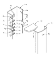
図1は本発明の実施例1のレシーバタンク付き熱交換器を示す正面図、図2はヘッダ4の上部分解斜視図、図3はヘッダ4の下部分解斜視図、図4はヘッダ4の上部斜視図、図5はヘッダ4の下部斜視図、図6は結合部材の分解斜視図、図7は同斜視図、図8は継手部材の分解斜視図、図9は同斜視図である。
図10はレシーバタンクの側断面図(一部のみ)、図11は本実施例1の要部拡大断面図、図12及び図13はタンクプレート8と第1分割部材の固定を説明する図である。
Example 1 will be described below.
1 is a front view showing a heat exchanger with a receiver tank according to a first embodiment of the present invention, FIG. 2 is an upper exploded perspective view of the
10 is a side sectional view of the receiver tank (only a part), FIG. 11 is an enlarged sectional view of the main part of the first embodiment, and FIGS. 12 and 13 are diagrams for explaining the fixing of the
先ず、全体構成を説明する。
図1に示すように、本実施例1のレシーバタンク付き熱交換器Aは、熱交換器本体1と、レシーバタンク2と、結合部材3が備えられている。
First, the overall configuration will be described.
As shown in FIG. 1, the heat exchanger A with a receiver tank according to the first embodiment includes a
熱交換器本体1は、左右に離間して配置される一対のヘッダ4,5と、これら両ヘッダ4,5の間に配置されるコア部6が備えられている。
図2、3に示すように、ヘッダ4は、断面が略コ字状のチューブプレート7と、断面が略椀状のタンクプレート8と、両プレート7,8の間に介在される板状の仕切り板D1,D2,D3,D4(仕切り板D2は図1参照)で構成されている。
The
As shown in FIGS. 2 and 3, the
チューブプレート7は、タンクプレート8よりも長手方向に長く形成される他、その長手方向両端部には、それぞれ切欠部7aを有して形成された一対の突出部7b,7bが形成されている。
また、チューブプレート7には、後述するコア部6の各チューブ6aの端部を挿通し固定するためのチューブ孔7cと、レインフォース10a,10bの端部を挿通し固定するためのレインフォース孔7dが形成されている。
The
The
また、ヘッダ4のディバイドD1〜D4が配置される部位において、チューブプレート7の内側にはそれぞれ対応する仕切り板D1〜D4の上面一部と下面一部を挟むように係止可能な半円柱状の係止段部7e,7eが対を成して突出した状態で設けられ、一方、該係止段部7e,7eと対向するタンクプレート8の位置には、それぞれ対応する仕切り板D1〜D4の凸部9を挿入可能な大きさの開口部8aが形成されている。
また、チューブプレート7には、それぞれ一対の切欠部7f,7fを有してタンクプレート8側に突出した一対の爪部7g,7gがチューブプレート8の長手方向に所定間隔で複数形成されている。
さらに、タンクプレート8の下部には、後述する継手部材11を介してレシーバタンク2が連通接続される僅かに縦長で楕円形状の連通孔8b,8cが形成されている。
Moreover, in the site | part where the dividers D1-D4 of the
The
Furthermore, slightly elongated and
そして、図4、5に示すように、両プレート7,8の間に各仕切り板D1〜D4が介在された状態で、チューブプレート7の内側にタンクプレート8が最中状に重ねられて接合される他、チューブプレート8の長手方向両端部において、突出部7b,7bが内側に折り曲げられてタンクプレート8の長手方向端部に近接または当接された状態で固定されると共に、爪部7g,7gがタンクプレート8の外側に加締められて固定されることにより、図1に示すように、ヘッダ4の内部に仕切り板D1,D2,D3,D4で仕切られた3つの室R2,R4,R5が形成されている。
4 and 5, with the partition plates D1 to D4 being interposed between the
ヘッダ5は、前述したヘッダ4と略左右対称形状に構成され、ヘッダ4と同様にその内部に仕切り板D5〜D8で仕切られた3つの室R1,R3,R6が形成される他、室R1に連通した状態でコネクタP1が設けられ、室R6に連通した状態でコネクタP2が設けられている。
The header 5 is configured in a substantially bilaterally symmetric shape with the
コア部6は、両端がそれぞれ対応するヘッダ4,5のチューブプレート孔7cに挿通し固定される複数のチューブ6aと、各チューブ6aと交互に配置される複数のフィン6bで構成され、その上下端部は、両端がそれぞれ対応するヘッダ4,5のレインフォース孔7dに挿通し固定された一対のレインフォース10a,10bで連結補強されている。
The core portion 6 includes a plurality of
図6、7に示すように、結合部材3は、レシーバタンク2を固定支持する機能と、ヘッダ4の室R4及び室R5をレシーバタンク2の内部に連通接続する機能を兼ねるものであって、継手部材11と、アダプタ部材12で構成されている。
As shown in FIGS. 6 and 7, the
図8、9に示すように、継手部材11は、第1分割部材13と第2分割部材14が互いに接合されることにより、全体が有底の略円筒形状に形成されている。
また、継手部材11の開口端部には、後述するアダプタ部材12の縮径部12dを挿入可能なアダプタ部材用接続部11aが形成される他、底部11bは緩やかなR形状に形成されている。
両分割部材13,14は、それぞれ有底の略半円筒形状に形成される他、第1分割部材13の側部13aには、タンクプレート8のそれぞれ対応する連通孔8b,8cに挿入可能な楕円形断面のヘッダ用接続部13b,13cが側方へ突出した状態で上下に離間して形成されている。
また、ヘッダ用接続部13b,13cはそれぞれ対応する連通孔8b,8cに合致する楕円形断面に形成され、それぞれの基端側には垂直な面で形成された段部13dがそれぞれ形成されている。
また、本実施例1では、第1分割部材13の内側に第2分割部材14が重ねられた状態で、該第1分割部材13の両縁部から外側へ略L字状に屈折した嵌合部13e,13e(位置決め手段に相当)及び底部13fの一部下面と、第2分割部材14の両縁部14a,14a(位置決め手段に相当)及び底面14bの一部下面をそれぞれ両分割部材13,14の接合部として接合されるようになっている。
なお、本実施例では第2分割部材14の両縁部14a,14aの一部が嵌合部13e,13eに当接しない部位があるが、この限りではない。
As shown in FIGS. 8 and 9, the
In addition, an adapter
Both the divided
Further, the
In the first embodiment, the second divided
In the present embodiment, there is a portion where both
また、両分割部材13,14は、それぞれ厚み1〜2mm前後のアルミ製板材を図外の金型でプレス成形加工して形成されたプレス成形加工品となっている。
なお、ヘッダ用接続部13b,13cの先端は上記プレス成形加工時に打ち抜かれて開口されるため、正確には打ち抜きプレス成形加工して形成されている。
また、両分割部材13,14の材料や厚み等は適宜設定でき、例えば、第1分割部13を第2分割部材14よりも肉厚に設定する場合もある。
従って、第1分割部材13は両接続部13b,13cを有して複雑な形状をしているものの、短時間で容易且つ安価に製造できるため、製造コストを低く抑えることができる。
また、押し出し加工や切削加工を用いないため、余分な部位に材料が残らずコンパクト化及び軽量化を実現できる。
The divided
Note that since the leading ends of the
Moreover, the material, thickness, etc. of both the
Therefore, although the
In addition, since extrusion or cutting is not used, material is not left in an extra portion, and a reduction in size and weight can be realized.
なお、第1分割部材13及び第2分割部材14を鋳造又は鍛造で製造することも可能である。
The first divided
アダプタ部材12は、略円筒形状に一体的に形成される他、その上部内側にはシール部材S1が装着された環状のシール溝12aが形成されると共に、このシール溝12aに近接して下方には雌螺子の溝12bが所定の範囲に形成されている。
また、アダプタ部材12の下部には、段部12cを有して縮径した縮径部12dが形成されている。
なお、アダプタ部材12の材料や厚み、両溝12a,12bの形成位置、形成範囲等は適宜設定できる。
The
Further, a reduced
The material and thickness of the
また、アダプタ部材12は、アルミ製の円柱状ブロック材を旋盤等により加工して厚み1〜2mm前後の円筒形状に形成した後、両溝12a,12bを切削加工して形成される。
従って、アダプタ部材12は複雑な形状ではないため、比較的単純な作業でもって容易に製造することができる。
The
Therefore, since the
図1に示すように、レシーバタンク2は、円筒形状の本体2aと、この本体2aの上端を塞ぐ略円盤状の蓋部材2bと、その下端に装着された略円筒状の接続管15で構成され、該本体2aの内部には図外の乾燥剤やフィルタ等の内部構造物が収容されている。
また、図10に示すように、本体2aの下端に装着された接続管15の外周には、径方向外側に拡径してレシーバタンク2の下端に当接するフランジ部15aが形成されると共に、このフランジ部15aの下方には雄螺子の溝15bが所定の範囲に形成されている。
As shown in FIG. 1, the
Further, as shown in FIG. 10, a
また、フランジ部15と本体2aに近接した位置に、これら両者のシールを行う環状のシール部材S2が装着されたシール溝15cが形成される他、溝15bの下方の上下に離間した位置は、シール部材S3,S4が装着されたシール溝15d,15eが形成されている。
In addition to the formation of a
そして、図11に示すように、ヘッダ4のタンクプレート8の連通孔8b,8cには、継手部材11のそれぞれ対応するヘッダ用接続部13b,13cが挿入された状態で固定され、さらに、継手部材11のアダプタ部材用接続部11aにはアダプタ部材12の段部12dが挿入された状態で固定されている。
Then, as shown in FIG. 11, the connecting
さらに、アダプタ部材12の溝12bにレシーバタンク2の接続管15の溝15bが螺合された状態で該レシーバタンク2が固定されている。
また、シール部材S1,S3,S4によって接続管15とアダプタ部材12とのシール性が確保されている。
Further, the
Further, the sealing performance between the connecting
従って、レシーバタンク2は、アダプタ部材12に対して着脱可能に固定される他、アダプタ部材12、継手部材11の接続部13b,13cを介してヘッダ4の室R4,R5に連通した状態となっている。
Accordingly, the
その他、本実施例1のレシーバタンク付き熱交換器Aは、全ての構成部材がアルミ製であり、各構成部材の接触部のうちの少なくとも一方にはろう材からなるクラッド層(ブレージングシート)が設けられている。 In addition, in the heat exchanger A with a receiver tank according to the first embodiment, all the constituent members are made of aluminum, and at least one of the contact portions of the respective constituent members has a clad layer (brazing sheet) made of a brazing material. Is provided.
次に、作用を説明する。
このように構成されたレシーバタンク付き熱交換器Aを製造する際には、先ず、熱交換器本体1を仮組みした後、図12に示すように、第1分割部材13のヘッダ用接続部13b,13cをヘッダ4のタンクプレート8のそれぞれ対応する連通孔8b,8cに挿入して、該ヘッダ用接続部13b,13cの各段部13dをタンクプレート8の外周面に当接させた状態とする。
Next, the operation will be described.
When manufacturing the heat exchanger A with a receiver tank configured as described above, first, the
次に、図12、13に示すように、径方向外側に拡径した段部20aを有する略楕円柱状の治具20,20をそれぞれ第1分割部材13の開口側からヘッダ用接続部13b,13cに挿入して該ヘッダ用接続部13b,13cを内側から外側へ拡径させることにより連通孔8b,8cに加締めて固定する。
この際、治具20,20の各段部20aがヘッダ用接続部13b,13cの各段部13dの内側に当接してタンクプレート8側へ押圧することにより、該ヘッダ用接続部13b,13cの各段部13dをタンクプレート8の外周面に密着させた状態で、ヘッダ用接続部13b,13cを連通孔8b,8cに加締めて固定できる。
なお、ヘッダ用接続部13b,13cは先端側に行くに従って大きく拡径するように塑性変形させて加締めても良い。
Next, as shown in FIGS. 12 and 13, the substantially elliptical
At this time, the
Note that the
従って、タンクプレート8を固定するための治具も必要なく、治具20を第1分割部材13の開口側から容易に挿入してヘッダ用接続部13b,13cを拡径させることができ、作業性が良い。
また、ヘッダ用接続部13b,13cの各段部13dがタンクプレート8の外周面に当接することによって、ヘッダ用接続部13b,13cの連通孔8a,8bへの挿入代を容易に位置決めできる。
なお、タンクプレート8を熱交換器本体1に仮組みする前に上記要領で予め第1分割部材13を固定しておくこともできる。この場合、治具20をタンクプレート8の内側から挿入してヘッダ用接続部13b,13cを連通孔8b,8cに加締めて固定することもできる。
Accordingly, there is no need for a jig for fixing the
Further, the stepped
Note that the first divided
次に、第1分割部材13の内側に第2分割部材14を最中状に重ね合わせて継手部材11を仮固定した後、アダプタ部材用接続部11aにアダプタ部材12の縮径部12dを挿入した状態とする。
この際、第1分割部材13の嵌合部13e,13eと第2分割部材14の両縁部14a,14aが嵌合し、これによって両者を適正に位置決めした状態で固定できる。
Next, after the second divided
At this time, the
次に、上記両分割部材13,14、アダプタ部材12が仮固定された熱交換器本体1を図外の加熱炉に搬送して熱処理することにより、各構成部材の接合部をろう付け固定する。
Next, the
この際、本実施例1では、第1分割部材13と第2分割部材14の内面にろう材を設けて、両分割部材13,14とアダプタ部材12を共にろう付け固定しており、これら三者の各接触部を少ないろう材で良好に固定できる配慮がなされている。
なお、ろう材を設定する部位は適宜設定でき、例えば、アダプタ部材12にろう材を設けても良い。
At this time, in the first embodiment, brazing material is provided on the inner surfaces of the first divided
In addition, the site | part which sets a brazing material can be set suitably, for example, you may provide a brazing material in the
また、両分割部材13,14、特に、タンクプレート8と直接接触する第1分割部材13がプレス成形加工品で重量が軽く熱マスが低いため、ろう付け固定の際におけるタンクプレート8が受ける熱影響を少なくして安定したろう付け固定を実現できる。
In addition, since both of the divided
また、継手部材11の両ヘッダ用接続部13b,13cがヘッダ4側に筒状に突出することによって、ヘッダ4の外周面と両ヘッダ用接続部13b,13cの間に空間O(図11参照)が形成されるため、これら両者の接触部を出来るだけ減らして、ろう付け固定の際におけるヘッダ4のスムーズな温度上昇及と温度下降を実現できる。
Further, the
また、ヘッダ用接続部13b,13cの各段部13dがタンクプレート8の外周面に当接することに加え、継手部材11のヘッダ用接続部13b,13cを楕円形断面としたため、円形断面とした場合に比べて、ろう付け固定の際及びその後においても継手部材11及びアダプタ部材12を安定して固定できる。
In addition to the stepped
次に、レシーバタンク2の接続管15の溝15bをアダプタ部材12の溝12bに螺合してフランジ部15の下端をアダプタ部材12の上端部に当接させることにより、レシーバタンク2を固定してレシーバタンク付き熱交換器Aの製造を終了する。
この際、レシーバタンク2の接続管15のフランジ部15aに締め付け工具を掛けて回転させることにより、上記螺合の作業を行うことができ、周辺部材のろう材が亀裂・破損する虞がない。
また、フランジ部15の下端がアダプタ部材12の上端部に当接するため、接続管15のアダプタ部12への過大な締め込みを防止できる。
従って、レシーバタンク2をアダプタ部材12に対して容易に着脱でき、熱交換器本体1の種類やコアサイズに応じてレシーバタンク2の種類やサイズを容易に設計・変更できる。
さらに、レシーバタンク2が損傷した場合には、アダプタ部材12から外して交換・修理でき、メンテナンス性に優れる。
Next, the
At this time, the screwing operation can be performed by applying a tightening tool to the
Moreover, since the lower end of the
Therefore, the
Furthermore, when the
このように構成されたレシーバタンク付き熱交換器Aは、車両に搭載された後、図外のコンプレッサ側からコネクタP1の接続孔16a(図1参照)を介してヘッダ5の室R1に流入した約70℃前後の流通媒体は、コア部6の室R1,R2に対応する各チューブ6aを流通する間にコア部6を通過する車両走行風またはファンによる強制風とフィン6bを介して熱交換された後、ヘッダ4の室R2に流入する。
The heat exchanger A with a receiver tank configured as described above flows into the chamber R1 of the header 5 from the compressor side (not shown) through the
また、室R2内の流通媒体は、コア部6の室R2,R3に対応する各チューブ6a5を流通してヘッダ5の室R3に流入し、次に、室R3内の流通媒体は、コア部6の室R3,R4に対応する各チューブ6aを流通する間にコア部6aを通過する車両走行風またはファンによる強制風と熱交換された後、ヘッダ4の室R4に流入する。
The distribution medium in the chamber R2 flows through the tubes 6a5 corresponding to the chambers R2 and R3 of the core portion 6 and flows into the chamber R3 of the header 5. Next, the distribution medium in the chamber R3 is the core portion. After flowing through the
次に、室R4内の流通媒体は、継手部材11の接続部13bからレシーバタンク2の本体内に流入して図外の内部構造物により気液分離された後、接続部13dから室R5に流入する。
Next, the flow medium in the chamber R4 flows into the main body of the
次に、室R5の液体の流通媒体は、コア部6の室R5,R6に対応する各チューブ6aを流通する間にコア部6を通過する車両走行風またはファンによる強制風と熱交換されることにより、約45℃前後まで過冷却されてヘッダ5の室R6に流入する。
Next, the liquid circulation medium in the chamber R5 is heat-exchanged with the vehicle running wind passing through the core section 6 or the forced wind by the fan while flowing through the
最後に、室R6内の流通媒体は、コネクタP2の接続孔16bから図外のエバポレータ側へ排出され、これによって、図1に示すように、熱交換器本体1は、室R1〜R4に対応する上側の凝縮部E1と室R5,R6に対応する下側の過冷却部E2に部分けされたコンデンサとして機能する。
Finally, the distribution medium in the chamber R6 is discharged from the
次に、効果を説明する。
以上、説明したように、本実施例1のレシーバタンク付き熱交換器にあっては、一対のヘッダ4,5間に、両端を両ヘッダ4,5に連通接続されるチューブ6aが複数配置され、両ヘッダ4,5の内部が仕切り板D1〜D8で仕切られて凝縮部E1と過冷却部E2に区分される熱交換器本体1と、熱交換器本体1の一方のヘッダ4の凝縮部E1と過冷却部E2に結合部材3を介して連通接続されるレシーバタンク2を備えるレシーバタンク付き熱交換器Aにおいて、結合部材3を、一方のヘッダ4の凝縮部E1と過冷却部E2に連通接続されるヘッダ用接続部13b,13cを有する継手部材11と、この継手部材11とレシーバタンク2に連通接続され、且つ、該レシーバタンク2が脱着可能に固定されるアダプタ部材12で構成し、継手部材11を、両ヘッダ用接続部13b,13cが形成された第1分割部材13と、この第1分割部材13に接合される第2分割部材14で構成したため、機能に必要のない部位に材料が残ることで重量が増加してしまうことを抑制して、レシーバタンクの脱着を実現しつつ、レシーバタンクと熱交換器本体を結合する結合部材の製造コスト及び重量の低減を実現できる。
Next, the effect will be described.
As described above, in the heat exchanger with a receiver tank of the first embodiment, a plurality of
また、上記のレシーバタンク付き熱交換器Aにあって、少なくとも第1分割部材13を金属製板材のプレス成形加工品としたので、結合部材3をより容易に製造することができる。
Moreover, in the heat exchanger A with a receiver tank described above, since at least the first divided
また、第1分割部材13に両ヘッダ用接続部13b,13cを形成したことにより、該両ヘッダ用接続部13b,13cを別体に分割した場合に比べてろう付け性及びシール性を向上でき、製品の信頼性を向上できる。
また、両分割部材13,14の接合部がヘッダ4から離れた位置に形成されるため、該接合部に亀裂・破損が生じた場合でも、補修する際の作業性が良い。
In addition, by forming the
Moreover, since the joint part of both the dividing
また、第1分割部材13及び第2分割部材14を有底の略半円筒形状にそれぞれ形成して、これら両者を互いに接合することにより、継手部材11を有底の略円筒形状に形成し、継手部材11の開口端部に、アダプタ部材12が連通接続されるアダプタ部材用接続部11aを形成したため、両分割部材13,14を接合する作業でもってアダプタ部材用接続部11aを形成できる。
加えて、継手部材11の底部を別体の蓋部材等で塞ぐ必要がないため、部品点数を減らしてコスト削減を図ることができる。
Further, the first divided
In addition, since it is not necessary to block the bottom of the
また、一方のヘッダ4の凝縮部E1及び過冷却部E2に連通孔8b,8cをそれぞれ形成し、両ヘッダ用接続部13b,13cを一方のヘッダ4側へ筒状に突出した状態で形成し、両ヘッダ用接続部13b,13cの基端側に垂直な面を有する段部13dを形成し、両ヘッダ用接続部13b,13cをそれぞれ対応する連通孔8b,8cに挿入した状態で固定すると共に、段部13dを一方のヘッダ4の外周面に当接させたため、両ヘッダ用接続部13b,13cをヘッダ4に対して位置決めした状態で固定できる上、これら両者の接触面積を増やして堅固に固定でき、ひいては、レシーバタンクを安定して固定支持できる。
Also,
また、両ヘッダ用接続部13b,13cを楕円形断面としたため、ヘッダ4との接触面積を増やして継手部材11、アダプタ部材12を安定して固定できる。
Further, since both
また、両ヘッダ用接続部13b,13cと一方のヘッダ4の外周面との間に空間Oを形成したため、ろう付け固定の際におけるヘッダ4が受ける熱影響を少なくして安定したろう付け固定を実現できる。
Further, since the space O is formed between the
また、第1分割部材13と第2分割部材14の接合部に、これら両者の位置決めを行う位置決め手段(嵌合部13e,13e、両縁部14a,14a)を設けたため、第1分割部材13と第2分割部材14を適正に位置決めした状態で固定できる。
Moreover, since the positioning part (
以上、本実施例を説明してきたが、本発明は上述の実施例に限られるものではなく、本発明の要旨を逸脱しない範囲の設計変更等があっても、本発明に含まれる。
例えば、本実施例1では両分割部材13,14をプレス成形加工品としたが、第1分割部材13のみプレス成形加工品としても良い。
Although the present embodiment has been described above, the present invention is not limited to the above-described embodiment, and design changes and the like within the scope not departing from the gist of the present invention are included in the present invention.
For example, in the first embodiment, both the divided
また、本実施例1で説明した各構成部材のろう材(ブレージングシート)を設ける部位は適宜設定できる。 Moreover, the site | part which provides the brazing material (brazing sheet) of each structural member demonstrated in the present Example 1 can be set suitably.
D1、D2、D3、D4、D5、D6、D7、D8 仕切り板
E1 凝縮部
E2 過冷却部
O 空間
P1、P2 コネクタ
R1、R2、R3、R4、R5、R6 室
1 熱交換器本体
2 レシーバタンク
2a 本体
2b 蓋部材
3 結合部材
4、5 ヘッダ
6 コア部
7 チューブプレート
7a 切欠部
7b 突出部
7c チューブ孔
7d レインフォース孔
7e 係止段部
7f 切欠部
7g 爪部
8 タンクプレート
8a 開口部
8b、8c 連通孔
9 凸部
10a、10b レインフォース
11 継手部材
11a アダプタ部材用接続部
11b (継手部材の)底部
12 アダプタ部材
12a シール溝
12b 溝
12c 段部
12d 縮径部
13 第1分割部材
13a 側部
13b、13c ヘッダ用接続部
13d 段部
13e 嵌合部
13f (第1分割部材の)底部
14 第2分割部材
14a 両縁部
14b (第2分割部材の)底部
15 接続管
15a フランジ部
15b 溝
15c、15d、15e シール溝
16a、16b 接続孔
20 治具
20a 段部
D1, D2, D3, D4, D5, D6, D7, D8 Partition plate E1 Condensing part E2 Supercooling part O Space P1, P2 Connector R1, R2, R3, R4, R5,
Claims (7)
前記熱交換器本体の一方のヘッダの凝縮部と過冷却部に結合部材を介して連通接続されるレシーバタンクを備えるレシーバタンク付き熱交換器において、
前記結合部材を、一方のヘッダの凝縮部と過冷却部に連通接続されるヘッダ用接続部を有する継手部材と、この継手部材とレシーバタンクに連通接続され、且つ、該レシーバタンクが脱着可能に固定されるアダプタ部材で構成し、
前記継手部材を、前記両ヘッダ用接続部が形成された第1分割部材と、この第1分割部材に接合される第2分割部材で構成したことを特徴とするレシーバタンク付き熱交換器。 Between the pair of headers, a plurality of tubes connected to both headers at both ends are arranged, and the inside of both headers is partitioned by a partition plate, and the heat exchanger body divided into a condensing part and a supercooling part,
In the heat exchanger with a receiver tank comprising a receiver tank connected to the condensing part and the supercooling part of one header of the heat exchanger main body via a coupling member,
The joint member is connected to a joint member having a header connecting portion that is connected to the condensing portion and the supercooling portion of one header, and the joint member is connected to the receiver tank so that the receiver tank can be detached. Consists of a fixed adapter member,
A heat exchanger with a receiver tank, wherein the joint member is composed of a first divided member in which the header connecting portions are formed and a second divided member joined to the first divided member.
少なくとも前記第1分割部材を金属製板材のプレス成形加工品としたことを特徴とするレシーバタンク付き熱交換器。 The heat exchanger with a receiver tank according to claim 1,
A heat exchanger with a receiver tank, wherein at least the first divided member is a press-formed product of a metal plate material.
前記第1分割部材及び第2分割部材を有底の略半円筒形状にそれぞれ形成して、これら両者を互いに接合することにより、前記継手部材を有底の略円筒形状に形成し、
前記継手部材の開口端部に、前記アダプタ部材が連通接続されるアダプタ部材用接続部を形成したことを特徴とするレシーバタンク付き熱交換器。 In the heat exchanger with a receiver tank of Claim 1 or 2,
Forming the first divided member and the second divided member in a substantially semi-cylindrical shape with a bottom, and joining them together to form the joint member in a substantially cylindrical shape with a bottom;
A heat exchanger with a receiver tank, wherein a connection portion for an adapter member to which the adapter member is connected in communication is formed at an opening end portion of the joint member.
前記一方のヘッダの凝縮部及び過冷却部に連通孔をそれぞれ形成し、
前記両ヘッダ用接続部を一方のヘッダ側へ筒状に突出した状態で形成し、
前記両ヘッダ用接続部の基端側に垂直な面を有する段部を形成し、
前記両ヘッダ用接続部をそれぞれ対応する連通孔に挿入した状態で固定すると共に、前記段部を一方のヘッダの外周面に当接させたことを特徴とするレシーバタンク付き熱交換器。 In the heat exchanger with a receiver tank in any one of Claims 1-3,
A communication hole is formed in each of the condensing part and the supercooling part of the one header,
Forming both header connecting portions projecting in a cylindrical shape toward one header side,
Forming a step portion having a surface perpendicular to the base end side of the connection portions for both headers;
A heat exchanger with a receiver tank, wherein the header connecting portions are fixed in a state of being inserted into corresponding communication holes, and the stepped portion is brought into contact with the outer peripheral surface of one header.
前記両ヘッダ用接続部を楕円形断面としたことを特徴とするレシーバタンク付き熱交換器。 In the heat exchanger with a receiver tank in any one of Claims 1-4,
A heat exchanger with a receiver tank, wherein the header connecting portions have an elliptical cross section.
前記両ヘッダ用接続部と一方のヘッダの外周面との間に空間を形成したことを特徴とするレシーバタンク付き熱交換器。 In the heat exchanger with a receiver tank in any one of Claims 1-5,
A heat exchanger with a receiver tank, wherein a space is formed between the connection portions for both headers and the outer peripheral surface of one header.
前記第1分割部材と第2分割部材の接合部に、これら両者の位置決めを行う位置決め手段を形成したことを特徴とするレシーバタンク付き熱交換器。 In the heat exchanger with a receiver tank in any one of Claims 1-6,
A heat exchanger with a receiver tank, wherein a positioning means for positioning both of the first divided member and the second divided member is formed at a joint portion between the first divided member and the second divided member.
Priority Applications (5)
| Application Number | Priority Date | Filing Date | Title |
|---|---|---|---|
| JP2005361465A JP2007163055A (en) | 2005-12-15 | 2005-12-15 | Heat exchanger with receiver tank |
| US12/097,436 US20100025028A1 (en) | 2005-12-15 | 2006-12-14 | Heat exchanger with receiver tank |
| PCT/JP2006/324904 WO2007069672A1 (en) | 2005-12-15 | 2006-12-14 | Heat exchanger with receiver tank |
| EP06834658A EP1962036A1 (en) | 2005-12-15 | 2006-12-14 | Heat exchanger with receiver tank |
| CNA2006800473901A CN101331367A (en) | 2005-12-15 | 2006-12-14 | Heat exchanger with receiver tank |
Applications Claiming Priority (1)
| Application Number | Priority Date | Filing Date | Title |
|---|---|---|---|
| JP2005361465A JP2007163055A (en) | 2005-12-15 | 2005-12-15 | Heat exchanger with receiver tank |
Publications (1)
| Publication Number | Publication Date |
|---|---|
| JP2007163055A true JP2007163055A (en) | 2007-06-28 |
Family
ID=38162974
Family Applications (1)
| Application Number | Title | Priority Date | Filing Date |
|---|---|---|---|
| JP2005361465A Pending JP2007163055A (en) | 2005-12-15 | 2005-12-15 | Heat exchanger with receiver tank |
Country Status (5)
| Country | Link |
|---|---|
| US (1) | US20100025028A1 (en) |
| EP (1) | EP1962036A1 (en) |
| JP (1) | JP2007163055A (en) |
| CN (1) | CN101331367A (en) |
| WO (1) | WO2007069672A1 (en) |
Families Citing this family (11)
| Publication number | Priority date | Publication date | Assignee | Title |
|---|---|---|---|---|
| JP4661953B2 (en) | 2008-12-04 | 2011-03-30 | ソニー株式会社 | Optical recording medium and manufacturing method thereof |
| DE102009038297A1 (en) * | 2009-08-21 | 2011-03-03 | Behr Gmbh & Co. Kg | Heat exchanger |
| EP2413045B1 (en) * | 2010-07-30 | 2014-02-26 | Grundfos Management A/S | Heat exchange unit |
| FR2975764B1 (en) * | 2011-05-26 | 2013-07-12 | Valeo Systemes Thermiques | COLLECTOR BOX, HEAT EXCHANGER COMPRISING SAID COLLECTOR BOX AND METHOD FOR CRIMPING SUCH BOX. |
| CN102242986B (en) * | 2011-07-05 | 2012-11-07 | 广东美的电器股份有限公司 | Parallel flow heat exchanger |
| US9267717B2 (en) * | 2012-06-21 | 2016-02-23 | Trane International Inc. | System and method of charge management |
| JP6035089B2 (en) * | 2012-09-12 | 2016-11-30 | 株式会社ケーヒン・サーマル・テクノロジー | Heat exchanger |
| JP5761252B2 (en) * | 2013-05-22 | 2015-08-12 | ダイキン工業株式会社 | Heat exchanger |
| US10935288B2 (en) * | 2017-08-28 | 2021-03-02 | Hanon Systems | Condenser |
| PL3457067T3 (en) * | 2017-09-15 | 2023-06-19 | Alfa Laval Corporate Ab | Baffle support and baffle |
| US10488087B2 (en) * | 2018-01-19 | 2019-11-26 | Denso International America, Inc. | Modulator assembly for condenser |
Citations (3)
| Publication number | Priority date | Publication date | Assignee | Title |
|---|---|---|---|---|
| JPH10288425A (en) * | 1997-04-11 | 1998-10-27 | Zexel Corp | Tank casing for receiver tank |
| JPH11270927A (en) * | 1998-03-20 | 1999-10-05 | Zexel:Kk | Connecting structure and connecting member for heat exchanger |
| JPH11351710A (en) * | 1998-06-10 | 1999-12-24 | Zexel:Kk | Receiver tank integrated type heat exchanger |
Family Cites Families (13)
| Publication number | Priority date | Publication date | Assignee | Title |
|---|---|---|---|---|
| US2153806A (en) * | 1935-05-07 | 1939-04-11 | Gen Motors Corp | Method of forming a heat exchange device |
| DE3900744A1 (en) * | 1989-01-12 | 1990-07-26 | Sueddeutsche Kuehler Behr | HEAT EXCHANGER |
| US6000465A (en) * | 1997-06-27 | 1999-12-14 | Mitsubishi Heavy Industries, Ltd. | Heat exchange with a receiver |
| JP3131774B2 (en) * | 1997-09-26 | 2001-02-05 | 漢拏空調株式会社 | Multi-flow condenser for vehicle air conditioner |
| FR2770629B1 (en) * | 1997-11-05 | 2000-02-11 | Valeo Thermique Moteur Sa | AIR CONDITIONING CONDENSER PROVIDED WITH AN INTERCHANGEABLE FLUID TANK |
| JP4167397B2 (en) * | 1998-12-02 | 2008-10-15 | 株式会社ヴァレオサーマルシステムズ | Heat exchanger |
| ATE441073T1 (en) * | 2001-11-08 | 2009-09-15 | Behr Gmbh & Co Kg | HEAT EXCHANGER |
| JP3955766B2 (en) * | 2002-02-20 | 2007-08-08 | 昭和電工株式会社 | Heat exchanger with receiver tank, receiver tank coupling member, receiver tank assembly structure of heat exchanger, and refrigeration system |
| TWI280340B (en) * | 2002-02-20 | 2007-05-01 | Showa Denko Kk | Heat exchanger with receiver tank, receiver tank connecting member, receiver tank mounting structure of heat exchanger and refrigeration system |
| JP3995527B2 (en) * | 2002-05-22 | 2007-10-24 | 日軽熱交株式会社 | Heat exchanger with receiver |
| KR100730567B1 (en) * | 2002-07-09 | 2007-06-20 | 한라공조주식회사 | Receiver-drier for an air-conditioning system and a method for making it |
| ITTO20030768A1 (en) * | 2003-10-02 | 2005-04-03 | Denso Thermal Systems Spa | CONDENSER FOR VEHICLES AND INTEGRATED RADIATOR BODY- |
| US20060123837A1 (en) * | 2004-12-10 | 2006-06-15 | Subros Limited | Receiver tank for a condensor and method of manufacturing the same |
-
2005
- 2005-12-15 JP JP2005361465A patent/JP2007163055A/en active Pending
-
2006
- 2006-12-14 WO PCT/JP2006/324904 patent/WO2007069672A1/en active Application Filing
- 2006-12-14 US US12/097,436 patent/US20100025028A1/en not_active Abandoned
- 2006-12-14 CN CNA2006800473901A patent/CN101331367A/en active Pending
- 2006-12-14 EP EP06834658A patent/EP1962036A1/en not_active Withdrawn
Patent Citations (3)
| Publication number | Priority date | Publication date | Assignee | Title |
|---|---|---|---|---|
| JPH10288425A (en) * | 1997-04-11 | 1998-10-27 | Zexel Corp | Tank casing for receiver tank |
| JPH11270927A (en) * | 1998-03-20 | 1999-10-05 | Zexel:Kk | Connecting structure and connecting member for heat exchanger |
| JPH11351710A (en) * | 1998-06-10 | 1999-12-24 | Zexel:Kk | Receiver tank integrated type heat exchanger |
Also Published As
| Publication number | Publication date |
|---|---|
| US20100025028A1 (en) | 2010-02-04 |
| CN101331367A (en) | 2008-12-24 |
| WO2007069672A1 (en) | 2007-06-21 |
| EP1962036A1 (en) | 2008-08-27 |
Similar Documents
| Publication | Publication Date | Title |
|---|---|---|
| JP2007163055A (en) | Heat exchanger with receiver tank | |
| US7578340B2 (en) | Heat exchanger | |
| JP2001289590A (en) | Heat exchanger | |
| MXPA06010948A (en) | Heat exchanger having an improved baffle. | |
| JP5663413B2 (en) | Serpentine heat exchanger | |
| JP3156565B2 (en) | Heat exchanger | |
| JP2011064379A (en) | Heat exchanger | |
| JP2007285547A (en) | Heat exchanger with receiver tank | |
| WO2020095797A1 (en) | Heat exchanger and method for manufacturing heat exchanger | |
| JPH11192833A (en) | Heat exchanger combination structure and integrated heat exchanger | |
| JP2007285538A (en) | Heat exchanger with receiver tank | |
| JP3894079B2 (en) | Connection structure of heat exchanger header and piping | |
| JP5851846B2 (en) | Heat exchanger and manufacturing method thereof | |
| JPH11223477A (en) | Composite heat exchanger for automobile and manufacture thereof | |
| JP2006010102A (en) | Stacked heat exchanger and its manufacturing method | |
| JP2007144502A (en) | Heat exchanger | |
| JP3317672B2 (en) | Heat exchanger | |
| WO2022172638A1 (en) | Heat exchanger | |
| JP2010085024A (en) | Heat exchanger | |
| JP4164145B2 (en) | Heat exchanger and car air conditioner using the same | |
| KR20180005397A (en) | Heat exchanger and method of fixing bracket thereof | |
| JP5305880B2 (en) | Header tank for heat exchanger and manufacturing method thereof | |
| JP2017089927A (en) | Aluminum heat exchanger | |
| JP2013044487A (en) | Liquid receiver-integrated heat exchanger | |
| JP5741470B2 (en) | Heat exchanger and method for manufacturing the same |
Legal Events
| Date | Code | Title | Description |
|---|---|---|---|
| A621 | Written request for application examination |
Free format text: JAPANESE INTERMEDIATE CODE: A621 Effective date: 20081127 |
|
| A131 | Notification of reasons for refusal |
Free format text: JAPANESE INTERMEDIATE CODE: A131 Effective date: 20110118 |
|
| A02 | Decision of refusal |
Free format text: JAPANESE INTERMEDIATE CODE: A02 Effective date: 20110802 |