JP2007160462A - Wire-saw - Google Patents
Wire-saw Download PDFInfo
- Publication number
- JP2007160462A JP2007160462A JP2005359372A JP2005359372A JP2007160462A JP 2007160462 A JP2007160462 A JP 2007160462A JP 2005359372 A JP2005359372 A JP 2005359372A JP 2005359372 A JP2005359372 A JP 2005359372A JP 2007160462 A JP2007160462 A JP 2007160462A
- Authority
- JP
- Japan
- Prior art keywords
- wire
- pulley
- work
- row
- supply
- Prior art date
- Legal status (The legal status is an assumption and is not a legal conclusion. Google has not performed a legal analysis and makes no representation as to the accuracy of the status listed.)
- Granted
Links
- 238000011084 recovery Methods 0.000 claims abstract description 31
- 238000004804 winding Methods 0.000 claims abstract description 11
- 230000007423 decrease Effects 0.000 claims description 8
- 230000010355 oscillation Effects 0.000 abstract 1
- 230000003247 decreasing effect Effects 0.000 description 3
- 230000002040 relaxant effect Effects 0.000 description 3
- 229910003460 diamond Inorganic materials 0.000 description 2
- 239000010432 diamond Substances 0.000 description 2
- 239000007788 liquid Substances 0.000 description 2
- 238000004519 manufacturing process Methods 0.000 description 2
- 238000000034 method Methods 0.000 description 2
- 239000002002 slurry Substances 0.000 description 2
- XUIMIQQOPSSXEZ-UHFFFAOYSA-N Silicon Chemical compound [Si] XUIMIQQOPSSXEZ-UHFFFAOYSA-N 0.000 description 1
- 239000006061 abrasive grain Substances 0.000 description 1
- 238000013459 approach Methods 0.000 description 1
- 239000000110 cooling liquid Substances 0.000 description 1
- 239000000463 material Substances 0.000 description 1
- 230000002093 peripheral effect Effects 0.000 description 1
- 239000011347 resin Substances 0.000 description 1
- 229920005989 resin Polymers 0.000 description 1
- 229910052710 silicon Inorganic materials 0.000 description 1
- 239000010703 silicon Substances 0.000 description 1
- 235000012431 wafers Nutrition 0.000 description 1
Images




Classifications
-
- B—PERFORMING OPERATIONS; TRANSPORTING
- B28—WORKING CEMENT, CLAY, OR STONE
- B28D—WORKING STONE OR STONE-LIKE MATERIALS
- B28D5/00—Fine working of gems, jewels, crystals, e.g. of semiconductor material; apparatus or devices therefor
- B28D5/04—Fine working of gems, jewels, crystals, e.g. of semiconductor material; apparatus or devices therefor by tools other than rotary type, e.g. reciprocating tools
- B28D5/045—Fine working of gems, jewels, crystals, e.g. of semiconductor material; apparatus or devices therefor by tools other than rotary type, e.g. reciprocating tools by cutting with wires or closed-loop blades
-
- B—PERFORMING OPERATIONS; TRANSPORTING
- B23—MACHINE TOOLS; METAL-WORKING NOT OTHERWISE PROVIDED FOR
- B23D—PLANING; SLOTTING; SHEARING; BROACHING; SAWING; FILING; SCRAPING; LIKE OPERATIONS FOR WORKING METAL BY REMOVING MATERIAL, NOT OTHERWISE PROVIDED FOR
- B23D57/00—Sawing machines or sawing devices not covered by one of the preceding groups B23D45/00 - B23D55/00
- B23D57/003—Sawing machines or sawing devices working with saw wires, characterised only by constructional features of particular parts
- B23D57/0061—Sawing machines or sawing devices working with saw wires, characterised only by constructional features of particular parts of devices for guiding or feeding saw wires
-
- B—PERFORMING OPERATIONS; TRANSPORTING
- B23—MACHINE TOOLS; METAL-WORKING NOT OTHERWISE PROVIDED FOR
- B23D—PLANING; SLOTTING; SHEARING; BROACHING; SAWING; FILING; SCRAPING; LIKE OPERATIONS FOR WORKING METAL BY REMOVING MATERIAL, NOT OTHERWISE PROVIDED FOR
- B23D57/00—Sawing machines or sawing devices not covered by one of the preceding groups B23D45/00 - B23D55/00
- B23D57/003—Sawing machines or sawing devices working with saw wires, characterised only by constructional features of particular parts
- B23D57/0069—Sawing machines or sawing devices working with saw wires, characterised only by constructional features of particular parts of devices for tensioning saw wires
Landscapes
- Engineering & Computer Science (AREA)
- Mechanical Engineering (AREA)
- Finish Polishing, Edge Sharpening, And Grinding By Specific Grinding Devices (AREA)
- Processing Of Stones Or Stones Resemblance Materials (AREA)
- Mechanical Treatment Of Semiconductor (AREA)
Abstract
Description
この発明は、高速で往復動又は一方走行させたワイヤ列にワークを押し当ててワークを切断する際、ワイヤ列に揺動を与えて切断の効率と精度を向上させたワイヤソー、更に詳しくは、ワイヤ列の揺動時にワイヤに張力変動が発生するのを防止し、ワイヤの切断発生を防いで安定した走行性が得られるようにしたワイヤソーに関する。 The present invention is a wire saw in which, when a workpiece is pressed against a wire row reciprocated at a high speed or unilaterally moved to cut the workpiece, the wire row is swung to improve cutting efficiency and accuracy. The present invention relates to a wire saw that prevents a change in tension from occurring when a wire row is swung and prevents a wire from being cut, thereby providing stable running performance.
従来、ワークの切断時にワイヤ列を揺動させるようにしたワイヤソーは、図9に示すように、供給側リール1から引き出したワイヤAが、モータ2によって駆動される供給側トラバーサ3と、複数のガイドプーリ4を介してエンコーダ5とテンションアーム6からなるテンション機構7と、ワイヤAの張力を測るロードセル8と、複数のガイドプーリ9に導かれた後、揺動円盤10に取付けた三本のワークローラ11に多数回巻回してワイヤ列を形成し、その後、複数のガイドプーリ12と、ワイヤAの張力を測るロードセル13と、エンコーダ14とテンションアーム15からなるテンション機構16と、複数のガイドプーリ17と、モータ18によって駆動される回収側トラバーサ19を通って回収側リール20に巻き取られるようになっている。
Conventionally, in a wire saw in which a wire row is swung when a workpiece is cut, as shown in FIG. 9, a wire A drawn from a supply-side reel 1 is supplied with a supply-
上記ワークローラ11は外周に溝が設けられ、このワークローラ11間の外周に溝を利用して巻回した上部ワイヤ列の直上に、ワーク固定テーブル21が図示しない適宜駆動手段により上下動するように配置され、このワーク固定テーブル21の下面に取付けたワークBをワイヤ列に向けて押し下げるようになっている。
The
上記したワイヤソーには、ワイヤ列のワーク切断位置の近傍にSiC、ダイヤモンド等の硬質砥粒を含有するスラリー液をノズル22で供給する遊離砥粒ワイヤソーと、前記ワイヤAにダイヤモンド粒を樹脂等で固定したワイヤを使用し、ワイヤ列のワーク切断位置に冷却液を供給しながら切断する固定砥粒ワイヤソーがある。
In the wire saw described above, a loose abrasive wire saw that supplies a slurry liquid containing hard abrasive grains such as SiC and diamond in the vicinity of the workpiece cutting position of the wire array with the
上記ワークローラ11を取付けた垂直の揺動円盤10は、機台23にクロスローラベアリング24を介して回転可能に支持され、後端に設けたプーリとベルトを介して駆動モータ25で、ワーク切断時に一定角度の往復回転と、ワークローラへのワイヤ巻付け時に全回転が付与されるようになっている。
The vertical oscillating
上記ワイヤ列の揺動機構は、ワークローラを取付けた揺動円盤をワーク切断時にこの揺動円盤をワークローラを回転駆動させるスピンドルとは別のモータ25で往復回転させることによってワイヤ列に一定角度の往復揺動を与え、ワークBへのワイヤAの接触を円弧状にすることで接触抵抗を弱め、スラリー液の持込みを良くさせて切断能力を増大させるようになっている。
The wire row rocking mechanism is configured to rotate the rocking disc on which the work roller is attached to the wire row at a certain angle by rotating the rocking disc reciprocally with a
従来、上記のようなワイヤソーのワークローラ11に対するワイヤAの誘導は、ワークローラ11に入る供給側のワイヤをワークローラ11に誘導する供給側ガイドプーリ9と、前記ワークローラ11から出る回収側のワイヤを外部に誘導する回収側ガイドプーリ12を、上記揺動円盤10の回転軸心から離れた外部の位置に固定配置した構造になっている(例えば、特許文献1参照)。
ところで、ワークローラ11に対して供給側ガイドプーリ9と回収側ガイドプーリ12を、揺動円盤10の回転軸心から離れた外部の位置に固定配置した構造では、ワイヤ列の揺動時に、ワークローラ11と供給側ガイドプーリ9及び回収側ガイドプーリ12の距離に変動が生じるため、ワイヤAが引っ張られたり緩んだりするという問題がある。
By the way, in the structure in which the supply-
また、最近のシリコンインゴット等の切断において、製造コストの削減から、ウエハの厚みを薄くし、ワークインゴットからの取数を増やしたり、ワイヤAの線径を細くして切断ロスを極力少なくする傾向にあり、このため、ワイヤソーにおいては、ワイヤAの線径を細くすると共に、製造効率の向上からワイヤAの線速の高速化が課題となっている。 Also, in recent cutting of silicon ingots, etc., due to the reduction of manufacturing cost, the thickness of wafers is reduced, the number of workpieces taken from work ingots is increased, or the wire diameter of wire A is reduced to reduce cutting loss as much as possible. For this reason, in the wire saw, the wire diameter of the wire A is reduced, and increasing the wire speed of the wire A is an issue from the viewpoint of improving manufacturing efficiency.
しかし、上記した従来のワイヤソーにおける揺動機構では、ワイヤ列の揺動時にワイヤ張力の変動が大きく、ワイヤ線径を細くしていった場合、揺動時にワイヤへの負荷が高まり、ワイヤが切断する場合があった。 However, in the conventional swing mechanism in the wire saw described above, when the wire string fluctuates greatly, the wire tension fluctuates greatly, and if the wire diameter is reduced, the load on the wire increases during the swing and the wire is cut. There was a case.
また、ワイヤ線速の高速化する場合にも、揺動時に上記と同様ワイヤが断線する場合があった。 Also, when the wire speed is increased, the wire may be disconnected as described above during swinging.
更に、ワークローラを直接正逆駆動してワイヤを高速で往復動させるワイヤソーにおいて、ワイヤ列の揺動によるワイヤの張力変化を吸収するため、ワイヤリールの駆動モータでワイヤリールの回転をワイヤの張力変化に追従させる方法も考えられるが、このような方法は、精度のよい駆動モータを必要とし、コスト的に高くなるという問題がある。 Furthermore, in a wire saw that reciprocally moves the wire at high speed by driving the work roller directly forward and backward, the wire reel rotation is controlled by the wire reel drive motor in order to absorb changes in the wire tension caused by the swing of the wire row. Although a method of following the change is also conceivable, such a method requires a high-precision drive motor and has a problem that it is expensive.
また、固定砥粒ワイヤソーにおいては、切削能力を向上させるために揺動角を大きくする傾向にあり、このため、揺動時のワイヤ張力の変動が大きくなるという問題がある。 Further, in the fixed abrasive wire saw, there is a tendency that the swing angle is increased in order to improve the cutting ability. For this reason, there is a problem that the fluctuation of the wire tension during the swing is increased.
そこで、この発明の課題は、上記した問題点を解決するため、ワイヤ列の揺動時に生じるワイヤ張力の変動をコスト的に安価な機械的構造で吸収することができ、ワイヤの高速化が可能になり、細線ワイヤであってもワイヤ列の揺動を利用した効率及び精度のよい切断が行えるワイヤソーを提供することにある。 Therefore, in order to solve the above-described problems, the object of the present invention is to absorb the fluctuation of the wire tension generated when the wire row is swung with a mechanical structure which is inexpensive in terms of cost, and the speed of the wire can be increased. Thus, an object of the present invention is to provide a wire saw that can perform cutting with high efficiency and accuracy using the swing of a wire row even for a thin wire.
上記の課題を解決するため、請求項1の発明は、揺動円盤に設けられた複数本のワークローラにワイヤを多数回巻回してワイヤ列を形成し、このワイヤ列のワイヤを高速で往復動又は一方走行させ、前記ワイヤ列にワークを押し当ててこのワークを複数に切り出すと共に、このワーク切断時にワイヤ列を揺動させるようにしたワイヤソーにおいて、前記ワークローラに入る供給側のワイヤをワークローラに誘導する供給側プーリと、前記ワークローラから出る回収側のワイヤを外部に誘導する回収側プーリを、上記揺動円盤の回転軸心上に同軸心状に配置した構成を採用したものである。 In order to solve the above-mentioned problem, the invention of claim 1 forms a wire row by winding a wire many times around a plurality of work rollers provided in an oscillating disk, and reciprocates the wires in the wire row at high speed. In a wire saw that is moved or moved in one direction, presses the workpiece against the wire row and cuts the workpiece into a plurality of pieces, and swings the wire row when cutting the workpiece, the wire on the supply side that enters the work roller is moved to the workpiece. A configuration in which a supply-side pulley that guides to a roller and a recovery-side pulley that guides a recovery-side wire coming out of the work roller to the outside are arranged coaxially on the rotation axis of the rocking disk. is there.
上記のように、供給側プーリと回収側プーリを揺動円盤の回転軸心上に同軸心状に配置すると、ワークローラが揺動してもワークローラと供給側プーリ及び回収側プーリの距離に変動が発生しないので、ワイヤ列を揺動させてもワイヤ張力の変動が生じないことになる。なお、揺動円盤に設けるワークローラは、三本には限定されず、例えば二本であってもよい。 As described above, when the supply pulley and the recovery pulley are arranged coaxially on the rotation axis of the swing disk, even if the work roller swings, the distance between the work roller, the supply pulley, and the recovery pulley is increased. Since no fluctuation occurs, the wire tension does not fluctuate even if the wire row is swung. The number of work rollers provided on the swing disk is not limited to three, and may be two, for example.
請求項2の発明は、揺動円盤に設けられた複数本のワークローラにワイヤを多数回巻回してワイヤ列を形成し、このワイヤ列のワイヤを高速で往復動又は一方走行させ、前記ワイヤ列にワークを押し当ててこのワークを複数に切り出すと共に、このワーク切断時にワイヤ列を揺動させるようにしたワイヤソーにおいて、前記揺動円盤に、ワークローラに対するワイヤの供給側に位置する供給側プーリと、ワークローラに対するワイヤの回収側に位置する回収側プーリを揺動円盤と一体に揺動するように設け、前記供給側プーリの外側に、ワイヤを供給側プーリに誘導するためと供給側プーリからのワイヤをワークローラに誘導するための2つの外側プーリと、前記回収側プーリの外側に、ワークローラからの回収ワイヤを回収側プーリに誘導するためと回収側プーリからのワイヤを外部に誘導するための2つの外側プーリをそれぞれ固定配置し、上記揺動円盤の揺動時に、ワークローラと外側プーリの距離の増減によるワイヤの張力変化に応じ、前記供給側プーリ及び回収側プーリをそれぞれ対応する外側プーリとの距離がワイヤの張力変化を打ち消す方向に増減する位置関係とした構成を採用したものである。 According to a second aspect of the present invention, a wire row is formed by winding a plurality of wires around a plurality of work rollers provided on an oscillating disk, and the wire in the wire row is reciprocated at a high speed or unidirectionally traveled. In a wire saw in which a workpiece is pressed against a row to cut the workpiece into a plurality of pieces and the wire row is swung at the time of cutting the workpiece, a supply-side pulley located on the supply side of the wire to the work roller on the swing disk And a recovery pulley located on the wire recovery side with respect to the work roller so as to swing integrally with the swing disk, and for guiding the wire to the supply pulley outside the supply pulley and the supply pulley Two outer pulleys for guiding the wire from the work roller to the work roller, and the collecting wire from the work roller to the collection side pulley outside the collecting pulley And two outer pulleys for guiding the wire from the recovery pulley to the outside are fixedly arranged, and the wire tension changes due to the increase / decrease of the distance between the work roller and the outer pulley when the swinging disk is swung. Accordingly, a configuration is adopted in which the distance between the supply-side pulley and the recovery-side pulley and the corresponding outer pulley is increased or decreased in a direction that cancels the tension change of the wire.
上記供給側プーリと回収側プーリを揺動円盤と一体に揺動するように設け、前記供給側プーリと回収側プーリの外側にそれぞれ対応する外側プーリを固定配置すると、ワークローラの揺動時によりワークローラと固定された外側プーリの距離が増減してワイヤ張力が変化するが、同じく揺動円盤に設けられた供給側プーリ及び回収側プーリも移動して固定された外側プーリとの距離が変化し、この変化が前記ワイヤの張力変化を打ち消す方向に移動するような位置関係であれば、揺動時に生じるワイヤの張力変動を吸収することができる。なお、揺動円盤に設けるワークローラは、三本には限定されず、例えば二本であってもよい。 When the supply side pulley and the recovery side pulley are provided so as to swing together with the swinging disk, and the outer pulleys corresponding to the outsides of the supply side pulley and the recovery side pulley are fixedly arranged, respectively, when the work roller swings, The wire tension changes as the distance between the work roller and the fixed outer pulley increases and decreases, but the distance between the fixed pulley and the supply pulley and recovery pulley provided on the swinging disk also moves. If the positional relationship is such that this change moves in a direction that cancels the tension change of the wire, it is possible to absorb fluctuations in the tension of the wire that occur during swinging. The number of work rollers provided on the swing disk is not limited to three, and may be two, for example.
請求項3の発明は、揺動円盤に設けられた複数本のワークローラにワイヤを多数回巻回してワイヤ列を形成し、このワイヤ列のワイヤを高速で往復動又は一方走行させ、前記ワイヤ列にワークを押し当ててこのワークを複数に切り出すと共に、このワーク切断時にワイヤ列を揺動させるようにしたワイヤソーにおいて、前記揺動円盤の外側に、ワイヤがワークローラに入る供給側の位置に供給側のワイヤをワークローラに誘導する供給側プーリと、前記ワークローラから出る回収側の位置に回収側のワイヤを外部に誘導する回収側プーリを、ワイヤの張力付加方向と緩和方向に移動可能に設け、上記揺動円盤の揺動時にワイヤの張力が減少する側は張力を付加する方向に、揺動円盤の揺動時にワイヤの張力が増加する側は張力を緩和する方向に制御するようにした構成を採用したものである。 According to a third aspect of the present invention, a wire array is formed by winding a plurality of wires around a plurality of work rollers provided on an oscillating disk, and the wires in the wire array are reciprocated at a high speed or run in one direction. In a wire saw in which a workpiece is pressed against a row and the workpiece is cut into a plurality of pieces and the wire row is swung when the workpiece is cut, the wire is placed outside the rocking disk at a position on the supply side where the wire enters the work roller. The supply-side pulley that guides the supply-side wire to the work roller and the recovery-side pulley that guides the recovery-side wire to the outside from the work roller can be moved in the direction of tension and relaxation of the wire. The side where the wire tension decreases when the rocking disk swings is in the direction of applying tension, and the side where the wire tension increases when the rocking disk swings is in the direction of relaxing tension. It is obtained by employing the configuration in which to control.
上記のように、供給側プーリと回収側プーリを揺動円盤の揺動時に、ワイヤの張力が減少する側は張力を付加する方向に、揺動円盤の揺動時にワイヤの張力が増加する側は張力を緩和する方向に制御すると、ワイヤ列の揺動時に生じるワイヤ張力の変動を吸収することができる。なお、揺動円盤に設けるワークローラは、三本には限定されず、例えば二本であってもよい。 As described above, when the supply pulley and the recovery pulley are oscillated by the oscillating disk, the wire tension decreasing side is in the direction of applying tension, and the wire tension is increasing when the oscillating disk is oscillating. By controlling in the direction of relaxing the tension, it is possible to absorb the fluctuation of the wire tension that occurs when the wire row swings. The number of work rollers provided on the swing disk is not limited to three, and may be two, for example.
請求項4の発明は、揺動円盤に設けられた三本のワークローラにワイヤを多数回巻回してワイヤ列を形成し、このワイヤ列のワイヤを高速で往復動又は一方走行させ、前記ワイヤ列にワークを押し当ててこのワークを複数に切り出すと共に、このワーク切断時にワイヤ列を揺動させるようにしたワイヤソーにおいて、前記揺動円盤に対してワイヤが出入りするワークローラを、このワークローラのワイヤ接触点が前記揺動円盤の回転軸心に一致するように配置した構成を採用したものである。 According to a fourth aspect of the present invention, a wire row is formed by winding a wire many times around three work rollers provided on an oscillating disk, and the wire in the wire row is reciprocated at a high speed or unidirectionally traveled. In a wire saw in which a workpiece is pressed against a row to cut out the workpiece into a plurality of pieces and the wire row is swung when the workpiece is cut, a work roller through which the wire enters and leaves the rocking disk is A configuration is adopted in which the wire contact point is arranged so as to coincide with the rotational axis of the oscillating disk.
上記一本のワークローラのワイヤ接触点を揺動円盤の回転軸心に一致させると、ワークローラは前記ワークローラのワイヤ接触点を支点に揺動し、ワイヤ列を揺動させてもワイヤ張力の変動が生じないことになる。 When the wire contact point of the single work roller is aligned with the rotational axis of the rocking disc, the work roller swings around the wire contact point of the work roller as a fulcrum, and the wire tension Will not occur.
ここで、上記揺動円盤は、ワークローラと別の駆動源により、ワーク切断時は一定角度を往復回転してワークローラに揺動を与え、ワークローラにワイヤを巻付ける時は全回転が与えられるようになっている。 Here, the oscillating disk is rotated by a reciprocating angle at a certain angle when the workpiece is cut by a driving source different from the work roller, and is oscillated to the work roller. It is supposed to be.
請求項1の発明によると、ワークローラからのワイヤの出入りが揺動の中心で行われるため、揺動によるワイヤのブレがなく、揺動を行っても張力の変動がなくなるため、ワイヤの制御が安定し、ワーク切断精度も向上する。 According to the first aspect of the present invention, since the wire enters and exits from the work roller at the center of the swing, the wire is not shaken by the swing, and the tension does not fluctuate even when the swing is performed. Is stable and the workpiece cutting accuracy is improved.
また、揺動機構を使用してもワイヤの張力変動が少ないため、ワイヤの細線化、ワイヤ走行の高速化が行える。 Further, even if the swing mechanism is used, the wire tension fluctuation is small, so that the wire can be thinned and the wire traveling speed can be increased.
請求項2の発明によると、ワイヤ列の揺動によるワークローラの位置変動に合わせて供給側プーリと回収側プーリが移動することによりワイヤの張力の変動を緩和することができ、ワイヤの制御が安定し、ワーク切断精度も向上する。 According to the second aspect of the present invention, the supply-side pulley and the recovery-side pulley can be moved in accordance with the position fluctuation of the work roller due to the swing of the wire row, so that the fluctuation of the wire tension can be alleviated, and the wire can be controlled. It is stable and the workpiece cutting accuracy is improved.
また、揺動機構を使用してもワイヤの張力変動が少ないため、ワイヤの細線化、ワイヤ走行の高速化が行える。 Further, even if the swing mechanism is used, the wire tension fluctuation is small, so that the wire can be thinned and the wire traveling speed can be increased.
請求項3の発明によると、ワイヤ列の揺動時に張力の変動にあわせて、張力の増減方向に供給側プーリと回収側プーリを移動制御するので、揺動を行ってもワイヤの張力の変動を緩和することができ、ワイヤの制御が安定し、ワーク切断精度も向上する。 According to the third aspect of the invention, since the supply side pulley and the recovery side pulley are controlled to move in the tension increasing / decreasing direction in accordance with the change in the tension when the wire row swings, the fluctuation in the wire tension can be controlled even if the swing is performed. Can be relaxed, the control of the wire is stabilized, and the workpiece cutting accuracy is also improved.
また、揺動機構を使用してもワイヤの張力変動が少ないため、ワイヤの細線化、ワイヤ走行の高速化が行える。 Further, even if the swing mechanism is used, the wire tension fluctuation is small, so that the wire can be thinned and the wire traveling speed can be increased.
請求項4の発明によると、ワイヤ列から出入りするワイヤの揺動基点が揺動中心と一致するため、揺動を行ってもワイヤの張力の変動を緩和することができ、ワイヤの制御が安定し、ワーク切断精度も向上する。
According to the invention of
また、揺動機構を使用してもワイヤの張力変動が少ないため、ワイヤの細線化、ワイヤ走行の高速化が行える。 Further, even if the swing mechanism is used, the wire tension fluctuation is small, so that the wire can be thinned and the wire traveling speed can be increased.
更に、何れの発明においても、ワイヤ列の揺動時にワイヤの張力の変動を吸収することができるので、ワイヤを駆動するモータのトルクにおいて、揺動運動による張力変動を考慮しなくてもよくなり、ワイヤリール駆動モータのコストダウンが図れると共に、ワイヤ切断の発生を防止でき、ワイヤの細線化と高速化が可能になる。 Furthermore, in any of the inventions, fluctuations in the tension of the wire can be absorbed when the wire row swings, so that it is not necessary to consider the fluctuations in tension due to the swinging motion in the torque of the motor that drives the wire. The cost of the wire reel drive motor can be reduced, the occurrence of wire cutting can be prevented, and the wire can be made thinner and faster.
以下、この発明の実施の形態を図示例に基づいて説明する。なお、ワイヤソーの基本的な全体構造は図9に示した通りであり、図9と同一部分には同一符号を付して説明する。 Hereinafter, embodiments of the present invention will be described based on illustrated examples. The basic overall structure of the wire saw is as shown in FIG. 9, and the same parts as those in FIG.
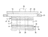
図1と図2のように、三本のワークローラ11を取付けた垂直の揺動円盤10は、機台23にクロスローラベアリング24を介して回転可能に支持され、後端に設けたプーリ26とベルト27を介して駆動モータ25で、ワーク切断時に一定角度の往復回転と、ワークローラ11へのワイヤAの巻付け時に全回転が付与されるようになっている。
As shown in FIGS. 1 and 2, the
上記ワークローラ11は、揺動円盤10の前面に水平状態で等間隔の配置となるよう、後端側が揺動円盤10で支持され、先端側は揺動円盤10の前面に設けた固定枠28の先端支持板29によって支持されている。
The
この三本のワークローラ11は、揺動円盤10の内部に組み込んだ適宜な機構(図示しない)で後部中央のスピンドル駆動軸30と連動され、プーリ31とベルト32を介してスピンドル軸駆動モータ33で、往復回転と全回転が付与されるようになっている。
The three
図1乃至図3は、この発明の第1の実施の形態を示し、上記ワークローラ11に入る供給側のワイヤA1をワークローラ11に誘導する供給側プーリ34と、前記ワークローラ11から出る回収側のワイヤA2を外部に誘導する回収側プーリ35を、上記揺動円盤10の回転軸心上に同軸心状に配置している。
FIGS. 1 to 3 show a first embodiment of the present invention. A supply-
上記供給側プーリ34と回収側プーリ35は、図1と図2のように、揺動円盤10の回転軸心上に同軸心状となるよう上記固定台28の対向面に取付けられている。
As shown in FIGS. 1 and 2, the
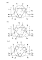
図3(a)乃至(c)は、第1の実施の形態の作動状態を示し、図3(a)のように、ワイヤ列の上部に位置するワーク切断部分が水平にある状態で、供給側のワイヤA1は外部の固定ガイドプーリ9から供給側プーリ34を通り、下位に位置するワークローラ11に進入し、また、回収側のワイヤA2は下位のワークローラ11から回収側プーリ35と外部の固定ガイドプーリ12を通って引き出されている。
FIGS. 3A to 3C show the operating state of the first embodiment. As shown in FIG. 3A, the workpiece cutting portion located at the upper part of the wire row is supplied in a horizontal state. The wire A 1 on the side passes through the
ワーク切断時に揺動円盤10を一定角度を左右に回動させると、図3(b)と(c)のように、ワイヤ列の上部に位置するワーク切断部分が揺動することになるが、この揺動時において、ワークローラ11に対するワイヤAの出入りが揺動の中心で行われるため、ワークローラ11と供給側プーリ34及び回収側プーリ35の距離が変動しないから、揺動によるワイヤAの張力変動がなく、ワイヤAの制御が安定し、ワークBの切断精度も向上する。
When the
なお、この第1の実施の形態は、二本のワークローラを用いたワイヤソーにも適用することができる。 The first embodiment can also be applied to a wire saw using two work rollers.
図4と図5は、この発明の第2の実施の形態を示し、ワークローラ11に対するワイヤAの供給側に供給側プーリ34と、ワークローラ11に対するワイヤAの回収側に回収側プーリ35を上記揺動円盤10に一体回動するように設け、前記供給側プーリ34の外側に、供給側のワイヤA1を供給側プーリ34に誘導する外側プーリ9a、及び、供給側プーリ34からのワイヤA1をワークローラ11に誘導する外側プーリ9bと、前記回収側プーリ35の外側に、ワークローラ11からの回収側のワイヤA2を回収側プーリ35に誘導する外側プーリ12b、及び、回収側プーリ35からのワイヤA2を外部に誘導する外側プーリ12aをそれぞれ固定配置している。
4 and 5 show a second embodiment of the present invention. A supply-
上記供給側プーリ34は、揺動円盤10の外周部で上部に位置するワイヤ列よりも下方の位置に取り付けられ、回収側プーリ35は、先端支持板29に突設したプーリ固定枠36の先端部に取付けられ、それぞれ揺動円盤10と一体に回動するようになっている。
The supply-
図5(a)乃至(c)は、第2の実施の形態の作動状態を示し、図5(a)のように、ワイヤ列の上部に位置するワーク切断部分が水平にある状態で、供給側のワイヤA1は外部の固定側の外側プーリ9aから揺動円盤10上の供給側プーリ34を通り、再度固定側にある外側プーリ9bを介して下位に位置するワークローラ11に進入し、また、回収側のワイヤA2は下位のワークローラ11から固定側の外側プーリ12bと揺動円盤10上の回収側プーリ35を通り、再度固定側にある外側プーリ12aから引き出されている。
FIGS. 5A to 5C show the operating state of the second embodiment. As shown in FIG. 5A, the workpiece cutting portion located at the upper part of the wire row is supplied in a horizontal state. The wire A 1 on the side passes through the
ワーク切断時に揺動円盤10を一定角度左右に回動させると、図5(b)と(c)のように、ワイヤ列の上部に位置するワーク切断部分が揺動することになるが、この揺動時において、ワイヤ列の揺動に合わせて供給側プーリ34と回収側プーリ35が揺動方向に回動することにより、ワークローラ11と供給側プーリ34及び回収側プーリ35の位置関係は変わらず、供給側においてはワークローラ11と外側プーリ9b間の間隔と、供給側プーリ34と外側プーリ9a、9b間の間隔は、一方が広がれば他方が接近することで供給側のワイヤA1の張力変動を吸収し、また、回収側においてはワークローラ11と外側プーリ12b間の間隔と、回収側プーリ35と外側プーリ12a、12b間の間隔は、一方が広がれば他方が接近することで回収側のワイヤA2の張力変動を吸収し、揺動を行ってもワイヤAの張力の変動を緩和することができ、ワイヤの制御が安定し、ワーク切断精度も向上する。
When the
この第2の実施形態では、外側プーリ9a、9bは、揺動円盤10の中心から見てワークローラ11と供給側プーリ34間において供給側プーリ34側に近接して配置され、外側プーリ12a、12bは外側プーリ9a、9bの対称位置に配置されており、揺動円盤10の揺動運動によるワークローラ11と外側プーリ9bの距離の変化は、供給側プーリ34と外側プーリ9a、9bとの往復距離が変化することで打ち消され、外側プーリ9aより外側(ワイヤの供給側)には揺動による張力変化の影響を及ぼさない。また、ワイヤの回収側においても同様の作用により外側プーリ12aより外側(ワイヤの回収側)には揺動による張力変化の影響を及ぼさない。
In the second embodiment, the
なお、この第2の実施の形態における供給側プーリ34、回収側プーリ35、及び各外側プーリ9a、9b、12a、12bの位置は、図示の構成に限定されるものではなく、要するに、揺動円盤10側のワークローラ11と固定側の外側プーリ9b、12bとの距離変動を揺動円盤10側の供給側プーリ34及び回収側プーリ35と対応する固定側の外側プーリ9a、9b、12a、12bとの距離変動により打ち消す位置関係であれば良く、これらは設計時の計算によって前もって求めることができる。
Note that the positions of the
図6と図7は、この発明の第3の実施の形態を示し、揺動円盤10の外側で、ワイヤAがワークローラ11に入る供給側の位置に、供給側のワイヤA1をワークローラ11に誘導する供給側プーリ34と、前記ワークローラ11から出る回収側の位置に回収側のワイヤA2を外部に誘導する回収側プーリ35を、ワイヤAの張力付加方向と緩和方向に移動可能に設け、前記揺動円盤10の往復回動時にワイヤAの張力が減少する側は張力を付加する方向に、ワイヤAの張力が増加する側は張力を緩和する方向に制御するようにしている。
6 and 7 show a third embodiment of the present invention, in which the wire A 1 on the supply side is placed on the supply side of the
上記供給側プーリ34と回収側プーリ35は、図6のように、機台23に固定したガイド枠37のレール38とスライダ39によって水平に移動可能に支持され、張力の変動に応じて伸縮作動するシリンダ等によって移動を制御する。
As shown in FIG. 6, the
図7(a)乃至(c)は、第3の実施の形態の作動状態を示し、図7(a)のように、ワイヤ列の上部に位置するワーク切断部分が水平にある状態で、供給側のワイヤA1は供給側プーリ34を通って下位に位置するワークローラ11に進入し、また、回収側のワイヤA2は下位のワークローラ11から回収側プーリ35を通って引き出され、供給側プーリ34と回収側プーリ35は、それぞれガイド枠37の中間に位置している。
FIGS. 7A to 7C show the operating state of the third embodiment. As shown in FIG. 7A, supply is performed in a state where the workpiece cutting portion located at the upper part of the wire row is horizontal. The wire A 1 on the side enters the
ワーク切断時に揺動円盤10を一定角度左右に回動させると、図7(b)と(c)のように、ワイヤ列の上部に位置するワーク切断部分が揺動することになるが、この揺動時において、供給側プーリ34と回収側プーリ35は、ワイヤAの張力が減少する側はワークローラ11から離れて張力を付加する方向に、同じく揺動時にワイヤAの張力が増加する側はワークローラ11に接近し、このように張力を緩和する方向に制御することで、ワイヤ列の揺動時に生じるワイヤAの張力の変動を吸収することができる。
When the
図8は、この発明の第4の実施の形態を示し、上記揺動円盤10に対して三本のワークローラ11を、その内のワイヤが出入りする一本のワークローラ11のワイヤ接触点11aが前記揺動円盤10の回転軸心に一致するように配置したものであり、図8(a)のように、ワイヤ列の上部に位置するワーク切断部分が水平にある状態で、供給側のワイヤA1はガイドプーリ9から下位に位置するワークローラ11に進入し、また、回収側のワイヤA2は下位のワークローラ11からガイドプーリ12に引き出されている。
FIG. 8 shows a fourth embodiment of the present invention, in which three
ワーク切断時に揺動円盤10を一定角度左右に回動させると、図8(b)と(c)のように、ワイヤAが出入りする一本のワークローラ11のワイヤ接触点11aを揺動円盤10の回転軸心に一致させておくと、ワークローラ11は前記ワークローラ11のワイヤ接触点11aを支点に揺動し、ワイヤ列を揺動させてもワイヤAの張力の変動が生じないことになる。
When the
なお、何れの実施の形態においても、ワークローラ11の揺動角度は大きく図示しているが、実際の揺動角度は、切断するワークの材質によっては適宜変更できる。また、ワーク切断中であっても適宜、揺動角度を変更することが可能である。
In any of the embodiments, the swing angle of the
A ワイヤ
B ワーク
1 供給側リール
2 モータ
3 供給側トラバーサ
4 ガイドプーリ
5 エンコーダ
6 テンションアーム
7 テンション機構
8 ロードセル
9 ガイドプーリ
9a,9b 外側プーリ
10 揺動円盤
11 ワークローラ
12 ガイドプーリ
12a,12b 外側プーリ
13 ロードセル
14 エンコーダ
15 テンションアーム
16 テンション機構
17 ガイドプーリ
18 モータ
19 回収側トラバーサ
20 回収側リール
21 ワーク固定テーブル
22 ノズル
23 固定機台
24 クロスローラベアリング
25 揺動モータ
26 プーリ
27 ベルト
28 固定枠
29 先端支持板
30 スピンドル駆動軸
31 プーリ
32 ベルト
33 スピンドル軸駆動モータ
34 供給側プーリ
35 回収側プーリ
36 プーリ固定枠
37 ガイド枠
38 レール
39 スライダ
A Wire B Workpiece 1
Claims (4)
Priority Applications (3)
| Application Number | Priority Date | Filing Date | Title |
|---|---|---|---|
| JP2005359372A JP4803717B2 (en) | 2005-12-13 | 2005-12-13 | Wire saw |
| US11/637,119 US7387118B2 (en) | 2005-12-13 | 2006-12-12 | Wire saw |
| CNA2006101672514A CN1982005A (en) | 2005-12-13 | 2006-12-12 | Wire saw |
Applications Claiming Priority (1)
| Application Number | Priority Date | Filing Date | Title |
|---|---|---|---|
| JP2005359372A JP4803717B2 (en) | 2005-12-13 | 2005-12-13 | Wire saw |
Publications (2)
| Publication Number | Publication Date |
|---|---|
| JP2007160462A true JP2007160462A (en) | 2007-06-28 |
| JP4803717B2 JP4803717B2 (en) | 2011-10-26 |
Family
ID=38138042
Family Applications (1)
| Application Number | Title | Priority Date | Filing Date |
|---|---|---|---|
| JP2005359372A Expired - Fee Related JP4803717B2 (en) | 2005-12-13 | 2005-12-13 | Wire saw |
Country Status (3)
| Country | Link |
|---|---|
| US (1) | US7387118B2 (en) |
| JP (1) | JP4803717B2 (en) |
| CN (1) | CN1982005A (en) |
Cited By (2)
| Publication number | Priority date | Publication date | Assignee | Title |
|---|---|---|---|---|
| JP2012236256A (en) * | 2011-05-12 | 2012-12-06 | Toyo Advanced Technologies Co Ltd | Wire saw device, and cutting method |
| JP2015155119A (en) * | 2014-02-20 | 2015-08-27 | 株式会社タカトリ | Wire saw and cutting work method |
Families Citing this family (25)
| Publication number | Priority date | Publication date | Assignee | Title |
|---|---|---|---|---|
| US9518340B2 (en) | 2006-04-07 | 2016-12-13 | Sixpoint Materials, Inc. | Method of growing group III nitride crystals |
| US8490658B2 (en) * | 2009-02-26 | 2013-07-23 | Saint-Gobain Abrasives, Inc. | Automatic winding of wire field in wire slicing machine |
| WO2011033541A1 (en) * | 2009-09-21 | 2011-03-24 | Pelmine S.R.L. | Multi-wire machine for cutting stone material |
| CN102166793A (en) * | 2011-02-21 | 2011-08-31 | 湖南宇晶机器实业有限公司 | Multiwire cutting machine dedicated to LEDs (light emitted diode) |
| CN103121227A (en) * | 2011-11-18 | 2013-05-29 | 常州贝斯塔德机械科技有限公司 | Multiline slicing machine |
| EP2890537A1 (en) | 2012-08-28 | 2015-07-08 | Sixpoint Materials Inc. | Group iii nitride wafer and its production method |
| EP2900851B1 (en) * | 2012-09-25 | 2019-01-09 | SixPoint Materials, Inc. | Method of growing group iii nitride crystals |
| WO2014051684A1 (en) | 2012-09-26 | 2014-04-03 | Sixpoint Materials, Inc. | Group iii nitride wafers and fabrication method and testing method |
| WO2014061053A1 (en) * | 2012-10-15 | 2014-04-24 | トーヨーエイテック株式会社 | Wire saw apparatus, and cut-machining method |
| CN102935667A (en) * | 2012-11-30 | 2013-02-20 | 浙江昀丰新能源科技有限公司 | Swing type fixed-orbit reciprocating multi-wire cutting device |
| CN104325568B (en) * | 2014-10-24 | 2016-05-25 | 苏州市汇峰机械设备有限公司 | One is waved cutting power head |
| CN104552404B (en) * | 2015-01-12 | 2016-06-29 | 国家电网公司 | Finger-type cutting equipment |
| CN106313351B (en) * | 2015-07-06 | 2018-02-23 | 天津职业技术师范大学 | A kind of multi-line cutting machine gauze tension measuring device and method |
| CN106626114B (en) * | 2016-12-29 | 2018-08-31 | 济南兰洁生物技术有限公司 | A kind of continuous delivery device of bar |
| CN107584687B (en) * | 2017-10-31 | 2024-03-26 | 乐山新天源太阳能科技有限公司 | Annular diamond wire squaring machine |
| CN107795301B (en) * | 2017-11-28 | 2024-06-25 | 青岛新胜石油机械有限公司 | Compact oil extraction mechanism and system |
| JP7225484B2 (en) * | 2018-06-04 | 2023-02-21 | 福井県 | Manufacturing method of coil for electrical equipment |
| JP6969579B2 (en) * | 2019-01-15 | 2021-11-24 | 信越半導体株式会社 | Work cutting method and wire saw |
| CN112388851B (en) * | 2019-08-14 | 2025-01-17 | 天通日进精密技术有限公司 | Wire cutting device |
| CN111660448B (en) * | 2020-06-29 | 2024-09-06 | 浙江精工新能源装备有限公司 | A device and method for changing the center distance of a slicer guide wheel |
| EP4059645A1 (en) * | 2021-03-19 | 2022-09-21 | Hilti Aktiengesellschaft | Wire saw and system comprising a wire saw and a remote control, and method and use of an actuating device for tensioning a wire in a wire saw |
| CN113832697B (en) * | 2021-09-27 | 2023-01-13 | 惠州市嘉盛鞋业有限公司 | Insole processing and forming equipment |
| CN114083704B (en) * | 2021-11-12 | 2022-08-26 | 大连理工大学 | Novel multi-wire cutting mechanism with variable interaxial distance |
| WO2023226771A1 (en) * | 2022-05-26 | 2023-11-30 | 长沙韵为科技有限公司 | Cutting apparatus and cutting method |
| CN115138934A (en) * | 2022-06-30 | 2022-10-04 | 青岛高测科技股份有限公司 | Wire cutting machine |
Citations (7)
| Publication number | Priority date | Publication date | Assignee | Title |
|---|---|---|---|---|
| JPH05104432A (en) * | 1991-10-08 | 1993-04-27 | Takatori Corp | Wire saw wire supply method |
| JPH10264143A (en) * | 1997-03-27 | 1998-10-06 | Mitsubishi Materials Shilicon Corp | Wire saw and ingot cutting method |
| JPH10336748A (en) * | 1997-06-04 | 1998-12-18 | Nec Corp | Ringing signal transmission method |
| JPH10337648A (en) * | 1997-06-04 | 1998-12-22 | Tokyo Seimitsu Co Ltd | Wire saw |
| JPH11198018A (en) * | 1998-01-16 | 1999-07-27 | Tokyo Seimitsu Co Ltd | Endless wire saw with fixed abrasive |
| JP2003165047A (en) * | 2001-11-28 | 2003-06-10 | Pmt:Kk | Ceramic processing equipment |
| JP2005014126A (en) * | 2003-06-24 | 2005-01-20 | Tdk Corp | Pitch variable processing method using multi-wire saw and multi-wire saw |
Family Cites Families (3)
| Publication number | Priority date | Publication date | Assignee | Title |
|---|---|---|---|---|
| JPH1110509A (en) * | 1997-06-24 | 1999-01-19 | Nippei Toyama Corp | Wire saw tensioning mechanism |
| US6024080A (en) * | 1997-07-07 | 2000-02-15 | Laser Technology West Limited | Apparatus and method for slicing a workpiece utilizing a diamond impregnated wire |
| US6279564B1 (en) * | 1997-07-07 | 2001-08-28 | John B. Hodsden | Rocking apparatus and method for slicing a workpiece utilizing a diamond impregnated wire |
-
2005
- 2005-12-13 JP JP2005359372A patent/JP4803717B2/en not_active Expired - Fee Related
-
2006
- 2006-12-12 CN CNA2006101672514A patent/CN1982005A/en active Pending
- 2006-12-12 US US11/637,119 patent/US7387118B2/en not_active Expired - Fee Related
Patent Citations (7)
| Publication number | Priority date | Publication date | Assignee | Title |
|---|---|---|---|---|
| JPH05104432A (en) * | 1991-10-08 | 1993-04-27 | Takatori Corp | Wire saw wire supply method |
| JPH10264143A (en) * | 1997-03-27 | 1998-10-06 | Mitsubishi Materials Shilicon Corp | Wire saw and ingot cutting method |
| JPH10336748A (en) * | 1997-06-04 | 1998-12-18 | Nec Corp | Ringing signal transmission method |
| JPH10337648A (en) * | 1997-06-04 | 1998-12-22 | Tokyo Seimitsu Co Ltd | Wire saw |
| JPH11198018A (en) * | 1998-01-16 | 1999-07-27 | Tokyo Seimitsu Co Ltd | Endless wire saw with fixed abrasive |
| JP2003165047A (en) * | 2001-11-28 | 2003-06-10 | Pmt:Kk | Ceramic processing equipment |
| JP2005014126A (en) * | 2003-06-24 | 2005-01-20 | Tdk Corp | Pitch variable processing method using multi-wire saw and multi-wire saw |
Cited By (2)
| Publication number | Priority date | Publication date | Assignee | Title |
|---|---|---|---|---|
| JP2012236256A (en) * | 2011-05-12 | 2012-12-06 | Toyo Advanced Technologies Co Ltd | Wire saw device, and cutting method |
| JP2015155119A (en) * | 2014-02-20 | 2015-08-27 | 株式会社タカトリ | Wire saw and cutting work method |
Also Published As
| Publication number | Publication date |
|---|---|
| US7387118B2 (en) | 2008-06-17 |
| JP4803717B2 (en) | 2011-10-26 |
| US20070131214A1 (en) | 2007-06-14 |
| CN1982005A (en) | 2007-06-20 |
Similar Documents
| Publication | Publication Date | Title |
|---|---|---|
| JP4803717B2 (en) | Wire saw | |
| CN105121109B (en) | Realize the scroll saw that lifting swings | |
| JP3539773B2 (en) | Wire saw and cutting method with wire saw | |
| JP2015155119A (en) | Wire saw and cutting work method | |
| KR101990664B1 (en) | Wire saw apparatus, and cut-machining method | |
| JP2011057426A (en) | Traverse device | |
| CN102166793A (en) | Multiwire cutting machine dedicated to LEDs (light emitted diode) | |
| JP6168689B2 (en) | Wire saw and cutting method | |
| JP2015033752A (en) | Wire saw | |
| JP5759775B2 (en) | Wire saw device and cutting method | |
| JP5441057B2 (en) | Wire saw | |
| JP6191835B2 (en) | Wire saw and wire groove jump prevention driving method | |
| JP6256870B2 (en) | Wire saw and control method thereof | |
| JP2011240449A (en) | Wire saw | |
| JP2011110643A5 (en) | ||
| JP2018158428A (en) | Wire saw and cutting processing method | |
| CN117226677A (en) | Double-roller ultrasonic excitation silicon carbide wire cutting device capable of cutting in large size | |
| JP5752396B2 (en) | Wire saw apparatus and wafer manufacturing method using the same | |
| CN103008782B (en) | Structure for eliminating saw band vibration of high-speed band sawing machine | |
| JP3032125B2 (en) | Wire saw equipment | |
| JP2012236256A (en) | Wire saw device, and cutting method | |
| JP2014151384A (en) | Wire saw | |
| JP4005199B2 (en) | Fine wire saw machine | |
| JPH1158208A (en) | Bobbin for wire saw | |
| JP5784976B2 (en) | Wire saw device and cutting method |
Legal Events
| Date | Code | Title | Description |
|---|---|---|---|
| A521 | Request for written amendment filed |
Free format text: JAPANESE INTERMEDIATE CODE: A821 Effective date: 20081215 |
|
| A621 | Written request for application examination |
Free format text: JAPANESE INTERMEDIATE CODE: A621 Effective date: 20081215 |
|
| A977 | Report on retrieval |
Free format text: JAPANESE INTERMEDIATE CODE: A971007 Effective date: 20101206 |
|
| A131 | Notification of reasons for refusal |
Free format text: JAPANESE INTERMEDIATE CODE: A131 Effective date: 20110419 |
|
| A521 | Request for written amendment filed |
Free format text: JAPANESE INTERMEDIATE CODE: A523 Effective date: 20110617 |
|
| TRDD | Decision of grant or rejection written | ||
| A01 | Written decision to grant a patent or to grant a registration (utility model) |
Free format text: JAPANESE INTERMEDIATE CODE: A01 Effective date: 20110712 |
|
| A01 | Written decision to grant a patent or to grant a registration (utility model) |
Free format text: JAPANESE INTERMEDIATE CODE: A01 |
|
| A61 | First payment of annual fees (during grant procedure) |
Free format text: JAPANESE INTERMEDIATE CODE: A61 Effective date: 20110805 |
|
| R150 | Certificate of patent or registration of utility model |
Free format text: JAPANESE INTERMEDIATE CODE: R150 |
|
| FPAY | Renewal fee payment (event date is renewal date of database) |
Free format text: PAYMENT UNTIL: 20140819 Year of fee payment: 3 |
|
| R250 | Receipt of annual fees |
Free format text: JAPANESE INTERMEDIATE CODE: R250 |
|
| LAPS | Cancellation because of no payment of annual fees |