JP2007073931A - Actuator equipment, manufacturing method thereof, and liquid injection head and liquid injection equipment - Google Patents
Actuator equipment, manufacturing method thereof, and liquid injection head and liquid injection equipment Download PDFInfo
- Publication number
- JP2007073931A JP2007073931A JP2006192068A JP2006192068A JP2007073931A JP 2007073931 A JP2007073931 A JP 2007073931A JP 2006192068 A JP2006192068 A JP 2006192068A JP 2006192068 A JP2006192068 A JP 2006192068A JP 2007073931 A JP2007073931 A JP 2007073931A
- Authority
- JP
- Japan
- Prior art keywords
- film
- upper electrode
- piezoelectric
- piezoelectric element
- actuator device
- Prior art date
- Legal status (The legal status is an assumption and is not a legal conclusion. Google has not performed a legal analysis and makes no representation as to the accuracy of the status listed.)
- Withdrawn
Links
- 239000007788 liquid Substances 0.000 title claims abstract description 26
- 238000004519 manufacturing process Methods 0.000 title claims abstract description 20
- 238000002347 injection Methods 0.000 title abstract 4
- 239000007924 injection Substances 0.000 title abstract 4
- 239000000758 substrate Substances 0.000 claims abstract description 52
- 238000000034 method Methods 0.000 claims abstract description 22
- 239000000463 material Substances 0.000 claims description 18
- 238000004544 sputter deposition Methods 0.000 claims description 11
- 229910052741 iridium Inorganic materials 0.000 claims description 10
- GKOZUEZYRPOHIO-UHFFFAOYSA-N iridium atom Chemical compound [Ir] GKOZUEZYRPOHIO-UHFFFAOYSA-N 0.000 claims description 10
- 239000002305 electric material Substances 0.000 abstract 3
- 239000000243 solution Substances 0.000 abstract 1
- 239000010408 film Substances 0.000 description 121
- 239000010410 layer Substances 0.000 description 58
- 238000006073 displacement reaction Methods 0.000 description 12
- 229910052451 lead zirconate titanate Inorganic materials 0.000 description 12
- 230000001681 protective effect Effects 0.000 description 12
- VYPSYNLAJGMNEJ-UHFFFAOYSA-N Silicium dioxide Chemical compound O=[Si]=O VYPSYNLAJGMNEJ-UHFFFAOYSA-N 0.000 description 10
- 230000000052 comparative effect Effects 0.000 description 10
- 239000002243 precursor Substances 0.000 description 9
- 238000004891 communication Methods 0.000 description 8
- 239000010936 titanium Substances 0.000 description 8
- XUIMIQQOPSSXEZ-UHFFFAOYSA-N Silicon Chemical compound [Si] XUIMIQQOPSSXEZ-UHFFFAOYSA-N 0.000 description 6
- RTAQQCXQSZGOHL-UHFFFAOYSA-N Titanium Chemical compound [Ti] RTAQQCXQSZGOHL-UHFFFAOYSA-N 0.000 description 6
- 239000012212 insulator Substances 0.000 description 6
- 229910052710 silicon Inorganic materials 0.000 description 6
- 239000010703 silicon Substances 0.000 description 6
- 239000010409 thin film Substances 0.000 description 6
- 229910052719 titanium Inorganic materials 0.000 description 6
- 239000013078 crystal Substances 0.000 description 5
- BASFCYQUMIYNBI-UHFFFAOYSA-N platinum Chemical compound [Pt] BASFCYQUMIYNBI-UHFFFAOYSA-N 0.000 description 5
- 230000010287 polarization Effects 0.000 description 5
- 235000012239 silicon dioxide Nutrition 0.000 description 5
- 239000000377 silicon dioxide Substances 0.000 description 5
- 239000010931 gold Substances 0.000 description 4
- 229910052751 metal Inorganic materials 0.000 description 4
- 239000002184 metal Substances 0.000 description 4
- 238000007789 sealing Methods 0.000 description 4
- 229910018072 Al 2 O 3 Inorganic materials 0.000 description 3
- PXHVJJICTQNCMI-UHFFFAOYSA-N Nickel Chemical compound [Ni] PXHVJJICTQNCMI-UHFFFAOYSA-N 0.000 description 3
- 230000003247 decreasing effect Effects 0.000 description 3
- 238000005238 degreasing Methods 0.000 description 3
- 238000009792 diffusion process Methods 0.000 description 3
- 238000010304 firing Methods 0.000 description 3
- 239000012528 membrane Substances 0.000 description 3
- 239000000203 mixture Substances 0.000 description 3
- TWNQGVIAIRXVLR-UHFFFAOYSA-N oxo(oxoalumanyloxy)alumane Chemical compound O=[Al]O[Al]=O TWNQGVIAIRXVLR-UHFFFAOYSA-N 0.000 description 3
- RVTZCBVAJQQJTK-UHFFFAOYSA-N oxygen(2-);zirconium(4+) Chemical compound [O-2].[O-2].[Zr+4] RVTZCBVAJQQJTK-UHFFFAOYSA-N 0.000 description 3
- 229910001928 zirconium oxide Inorganic materials 0.000 description 3
- XKRFYHLGVUSROY-UHFFFAOYSA-N Argon Chemical compound [Ar] XKRFYHLGVUSROY-UHFFFAOYSA-N 0.000 description 2
- KRHYYFGTRYWZRS-UHFFFAOYSA-N Fluorane Chemical compound F KRHYYFGTRYWZRS-UHFFFAOYSA-N 0.000 description 2
- 239000004734 Polyphenylene sulfide Substances 0.000 description 2
- 229910052581 Si3N4 Inorganic materials 0.000 description 2
- 239000000853 adhesive Substances 0.000 description 2
- 230000001070 adhesive effect Effects 0.000 description 2
- 239000000956 alloy Substances 0.000 description 2
- 229910045601 alloy Inorganic materials 0.000 description 2
- 230000015572 biosynthetic process Effects 0.000 description 2
- 239000011248 coating agent Substances 0.000 description 2
- 238000000576 coating method Methods 0.000 description 2
- 230000006835 compression Effects 0.000 description 2
- 238000007906 compression Methods 0.000 description 2
- 230000006378 damage Effects 0.000 description 2
- 238000001035 drying Methods 0.000 description 2
- PCHJSUWPFVWCPO-UHFFFAOYSA-N gold Chemical compound [Au] PCHJSUWPFVWCPO-UHFFFAOYSA-N 0.000 description 2
- 229910052737 gold Inorganic materials 0.000 description 2
- 238000010438 heat treatment Methods 0.000 description 2
- 239000011810 insulating material Substances 0.000 description 2
- HFGPZNIAWCZYJU-UHFFFAOYSA-N lead zirconate titanate Chemical compound [O-2].[O-2].[O-2].[O-2].[O-2].[Ti+4].[Zr+4].[Pb+2] HFGPZNIAWCZYJU-UHFFFAOYSA-N 0.000 description 2
- 238000001459 lithography Methods 0.000 description 2
- 239000010955 niobium Substances 0.000 description 2
- 229910052697 platinum Inorganic materials 0.000 description 2
- 229920000069 polyphenylene sulfide Polymers 0.000 description 2
- HQVNEWCFYHHQES-UHFFFAOYSA-N silicon nitride Chemical compound N12[Si]34N5[Si]62N3[Si]51N64 HQVNEWCFYHHQES-UHFFFAOYSA-N 0.000 description 2
- 238000003980 solgel method Methods 0.000 description 2
- 239000010935 stainless steel Substances 0.000 description 2
- 229910001220 stainless steel Inorganic materials 0.000 description 2
- 238000000018 DNA microarray Methods 0.000 description 1
- FYYHWMGAXLPEAU-UHFFFAOYSA-N Magnesium Chemical compound [Mg] FYYHWMGAXLPEAU-UHFFFAOYSA-N 0.000 description 1
- 229910020215 Pb(Mg1/3Nb2/3)O3PbTiO3 Inorganic materials 0.000 description 1
- 229910052786 argon Inorganic materials 0.000 description 1
- 229910052797 bismuth Inorganic materials 0.000 description 1
- JCXGWMGPZLAOME-UHFFFAOYSA-N bismuth atom Chemical compound [Bi] JCXGWMGPZLAOME-UHFFFAOYSA-N 0.000 description 1
- 239000003054 catalyst Substances 0.000 description 1
- 239000000919 ceramic Substances 0.000 description 1
- 229910010293 ceramic material Inorganic materials 0.000 description 1
- 238000006243 chemical reaction Methods 0.000 description 1
- 238000005520 cutting process Methods 0.000 description 1
- 238000000354 decomposition reaction Methods 0.000 description 1
- 230000002950 deficient Effects 0.000 description 1
- 238000010586 diagram Methods 0.000 description 1
- 238000001312 dry etching Methods 0.000 description 1
- 239000007772 electrode material Substances 0.000 description 1
- 238000011156 evaluation Methods 0.000 description 1
- 230000001747 exhibiting effect Effects 0.000 description 1
- 238000011049 filling Methods 0.000 description 1
- 239000007789 gas Substances 0.000 description 1
- 239000011521 glass Substances 0.000 description 1
- 239000002241 glass-ceramic Substances 0.000 description 1
- 239000004973 liquid crystal related substance Substances 0.000 description 1
- 229910052749 magnesium Inorganic materials 0.000 description 1
- 239000011777 magnesium Substances 0.000 description 1
- 229910044991 metal oxide Inorganic materials 0.000 description 1
- 150000004706 metal oxides Chemical class 0.000 description 1
- 239000013212 metal-organic material Substances 0.000 description 1
- 229910052759 nickel Inorganic materials 0.000 description 1
- 229910052758 niobium Inorganic materials 0.000 description 1
- GUCVJGMIXFAOAE-UHFFFAOYSA-N niobium atom Chemical compound [Nb] GUCVJGMIXFAOAE-UHFFFAOYSA-N 0.000 description 1
- 150000002902 organometallic compounds Chemical class 0.000 description 1
- 230000003647 oxidation Effects 0.000 description 1
- 238000007254 oxidation reaction Methods 0.000 description 1
- BPUBBGLMJRNUCC-UHFFFAOYSA-N oxygen(2-);tantalum(5+) Chemical compound [O-2].[O-2].[O-2].[O-2].[O-2].[Ta+5].[Ta+5] BPUBBGLMJRNUCC-UHFFFAOYSA-N 0.000 description 1
- 238000005192 partition Methods 0.000 description 1
- 238000000059 patterning Methods 0.000 description 1
- 230000002093 peripheral effect Effects 0.000 description 1
- 238000001552 radio frequency sputter deposition Methods 0.000 description 1
- VSZWPYCFIRKVQL-UHFFFAOYSA-N selanylidenegallium;selenium Chemical compound [Se].[Se]=[Ga].[Se]=[Ga] VSZWPYCFIRKVQL-UHFFFAOYSA-N 0.000 description 1
- 239000002356 single layer Substances 0.000 description 1
- 239000002904 solvent Substances 0.000 description 1
- 238000000992 sputter etching Methods 0.000 description 1
- PBCFLUZVCVVTBY-UHFFFAOYSA-N tantalum pentoxide Inorganic materials O=[Ta](=O)O[Ta](=O)=O PBCFLUZVCVVTBY-UHFFFAOYSA-N 0.000 description 1
- 238000003466 welding Methods 0.000 description 1
- 229910052727 yttrium Inorganic materials 0.000 description 1
- VWQVUPCCIRVNHF-UHFFFAOYSA-N yttrium atom Chemical compound [Y] VWQVUPCCIRVNHF-UHFFFAOYSA-N 0.000 description 1
- 229910052726 zirconium Inorganic materials 0.000 description 1
- 150000003754 zirconium Chemical class 0.000 description 1
Images


Classifications
-
- H—ELECTRICITY
- H04—ELECTRIC COMMUNICATION TECHNIQUE
- H04R—LOUDSPEAKERS, MICROPHONES, GRAMOPHONE PICK-UPS OR LIKE ACOUSTIC ELECTROMECHANICAL TRANSDUCERS; DEAF-AID SETS; PUBLIC ADDRESS SYSTEMS
- H04R17/00—Piezoelectric transducers; Electrostrictive transducers
-
- B—PERFORMING OPERATIONS; TRANSPORTING
- B41—PRINTING; LINING MACHINES; TYPEWRITERS; STAMPS
- B41J—TYPEWRITERS; SELECTIVE PRINTING MECHANISMS, i.e. MECHANISMS PRINTING OTHERWISE THAN FROM A FORME; CORRECTION OF TYPOGRAPHICAL ERRORS
- B41J2/00—Typewriters or selective printing mechanisms characterised by the printing or marking process for which they are designed
- B41J2/005—Typewriters or selective printing mechanisms characterised by the printing or marking process for which they are designed characterised by bringing liquid or particles selectively into contact with a printing material
- B41J2/01—Ink jet
- B41J2/135—Nozzles
- B41J2/16—Production of nozzles
- B41J2/1607—Production of print heads with piezoelectric elements
- B41J2/161—Production of print heads with piezoelectric elements of film type, deformed by bending and disposed on a diaphragm
-
- B—PERFORMING OPERATIONS; TRANSPORTING
- B41—PRINTING; LINING MACHINES; TYPEWRITERS; STAMPS
- B41J—TYPEWRITERS; SELECTIVE PRINTING MECHANISMS, i.e. MECHANISMS PRINTING OTHERWISE THAN FROM A FORME; CORRECTION OF TYPOGRAPHICAL ERRORS
- B41J2/00—Typewriters or selective printing mechanisms characterised by the printing or marking process for which they are designed
- B41J2/005—Typewriters or selective printing mechanisms characterised by the printing or marking process for which they are designed characterised by bringing liquid or particles selectively into contact with a printing material
- B41J2/01—Ink jet
- B41J2/135—Nozzles
- B41J2/16—Production of nozzles
- B41J2/1621—Manufacturing processes
- B41J2/1623—Manufacturing processes bonding and adhesion
-
- B—PERFORMING OPERATIONS; TRANSPORTING
- B41—PRINTING; LINING MACHINES; TYPEWRITERS; STAMPS
- B41J—TYPEWRITERS; SELECTIVE PRINTING MECHANISMS, i.e. MECHANISMS PRINTING OTHERWISE THAN FROM A FORME; CORRECTION OF TYPOGRAPHICAL ERRORS
- B41J2/00—Typewriters or selective printing mechanisms characterised by the printing or marking process for which they are designed
- B41J2/005—Typewriters or selective printing mechanisms characterised by the printing or marking process for which they are designed characterised by bringing liquid or particles selectively into contact with a printing material
- B41J2/01—Ink jet
- B41J2/135—Nozzles
- B41J2/16—Production of nozzles
- B41J2/1621—Manufacturing processes
- B41J2/1626—Manufacturing processes etching
- B41J2/1628—Manufacturing processes etching dry etching
-
- B—PERFORMING OPERATIONS; TRANSPORTING
- B41—PRINTING; LINING MACHINES; TYPEWRITERS; STAMPS
- B41J—TYPEWRITERS; SELECTIVE PRINTING MECHANISMS, i.e. MECHANISMS PRINTING OTHERWISE THAN FROM A FORME; CORRECTION OF TYPOGRAPHICAL ERRORS
- B41J2/00—Typewriters or selective printing mechanisms characterised by the printing or marking process for which they are designed
- B41J2/005—Typewriters or selective printing mechanisms characterised by the printing or marking process for which they are designed characterised by bringing liquid or particles selectively into contact with a printing material
- B41J2/01—Ink jet
- B41J2/135—Nozzles
- B41J2/16—Production of nozzles
- B41J2/1621—Manufacturing processes
- B41J2/1626—Manufacturing processes etching
- B41J2/1629—Manufacturing processes etching wet etching
-
- B—PERFORMING OPERATIONS; TRANSPORTING
- B41—PRINTING; LINING MACHINES; TYPEWRITERS; STAMPS
- B41J—TYPEWRITERS; SELECTIVE PRINTING MECHANISMS, i.e. MECHANISMS PRINTING OTHERWISE THAN FROM A FORME; CORRECTION OF TYPOGRAPHICAL ERRORS
- B41J2/00—Typewriters or selective printing mechanisms characterised by the printing or marking process for which they are designed
- B41J2/005—Typewriters or selective printing mechanisms characterised by the printing or marking process for which they are designed characterised by bringing liquid or particles selectively into contact with a printing material
- B41J2/01—Ink jet
- B41J2/135—Nozzles
- B41J2/16—Production of nozzles
- B41J2/1621—Manufacturing processes
- B41J2/1632—Manufacturing processes machining
-
- B—PERFORMING OPERATIONS; TRANSPORTING
- B41—PRINTING; LINING MACHINES; TYPEWRITERS; STAMPS
- B41J—TYPEWRITERS; SELECTIVE PRINTING MECHANISMS, i.e. MECHANISMS PRINTING OTHERWISE THAN FROM A FORME; CORRECTION OF TYPOGRAPHICAL ERRORS
- B41J2/00—Typewriters or selective printing mechanisms characterised by the printing or marking process for which they are designed
- B41J2/005—Typewriters or selective printing mechanisms characterised by the printing or marking process for which they are designed characterised by bringing liquid or particles selectively into contact with a printing material
- B41J2/01—Ink jet
- B41J2/135—Nozzles
- B41J2/16—Production of nozzles
- B41J2/1621—Manufacturing processes
- B41J2/1635—Manufacturing processes dividing the wafer into individual chips
-
- B—PERFORMING OPERATIONS; TRANSPORTING
- B41—PRINTING; LINING MACHINES; TYPEWRITERS; STAMPS
- B41J—TYPEWRITERS; SELECTIVE PRINTING MECHANISMS, i.e. MECHANISMS PRINTING OTHERWISE THAN FROM A FORME; CORRECTION OF TYPOGRAPHICAL ERRORS
- B41J2/00—Typewriters or selective printing mechanisms characterised by the printing or marking process for which they are designed
- B41J2/005—Typewriters or selective printing mechanisms characterised by the printing or marking process for which they are designed characterised by bringing liquid or particles selectively into contact with a printing material
- B41J2/01—Ink jet
- B41J2/135—Nozzles
- B41J2/16—Production of nozzles
- B41J2/1621—Manufacturing processes
- B41J2/164—Manufacturing processes thin film formation
- B41J2/1646—Manufacturing processes thin film formation thin film formation by sputtering
-
- H—ELECTRICITY
- H04—ELECTRIC COMMUNICATION TECHNIQUE
- H04R—LOUDSPEAKERS, MICROPHONES, GRAMOPHONE PICK-UPS OR LIKE ACOUSTIC ELECTROMECHANICAL TRANSDUCERS; DEAF-AID SETS; PUBLIC ADDRESS SYSTEMS
- H04R31/00—Apparatus or processes specially adapted for the manufacture of transducers or diaphragms therefor
-
- B—PERFORMING OPERATIONS; TRANSPORTING
- B41—PRINTING; LINING MACHINES; TYPEWRITERS; STAMPS
- B41J—TYPEWRITERS; SELECTIVE PRINTING MECHANISMS, i.e. MECHANISMS PRINTING OTHERWISE THAN FROM A FORME; CORRECTION OF TYPOGRAPHICAL ERRORS
- B41J2/00—Typewriters or selective printing mechanisms characterised by the printing or marking process for which they are designed
- B41J2/005—Typewriters or selective printing mechanisms characterised by the printing or marking process for which they are designed characterised by bringing liquid or particles selectively into contact with a printing material
- B41J2/01—Ink jet
- B41J2/135—Nozzles
- B41J2/14—Structure thereof only for on-demand ink jet heads
- B41J2/14201—Structure of print heads with piezoelectric elements
- B41J2/14233—Structure of print heads with piezoelectric elements of film type, deformed by bending and disposed on a diaphragm
- B41J2002/14241—Structure of print heads with piezoelectric elements of film type, deformed by bending and disposed on a diaphragm having a cover around the piezoelectric thin film element
-
- Y—GENERAL TAGGING OF NEW TECHNOLOGICAL DEVELOPMENTS; GENERAL TAGGING OF CROSS-SECTIONAL TECHNOLOGIES SPANNING OVER SEVERAL SECTIONS OF THE IPC; TECHNICAL SUBJECTS COVERED BY FORMER USPC CROSS-REFERENCE ART COLLECTIONS [XRACs] AND DIGESTS
- Y10—TECHNICAL SUBJECTS COVERED BY FORMER USPC
- Y10T—TECHNICAL SUBJECTS COVERED BY FORMER US CLASSIFICATION
- Y10T29/00—Metal working
- Y10T29/42—Piezoelectric device making
-
- Y—GENERAL TAGGING OF NEW TECHNOLOGICAL DEVELOPMENTS; GENERAL TAGGING OF CROSS-SECTIONAL TECHNOLOGIES SPANNING OVER SEVERAL SECTIONS OF THE IPC; TECHNICAL SUBJECTS COVERED BY FORMER USPC CROSS-REFERENCE ART COLLECTIONS [XRACs] AND DIGESTS
- Y10—TECHNICAL SUBJECTS COVERED BY FORMER USPC
- Y10T—TECHNICAL SUBJECTS COVERED BY FORMER US CLASSIFICATION
- Y10T29/00—Metal working
- Y10T29/49—Method of mechanical manufacture
- Y10T29/49002—Electrical device making
- Y10T29/49117—Conductor or circuit manufacturing
- Y10T29/49204—Contact or terminal manufacturing
- Y10T29/49224—Contact or terminal manufacturing with coating
-
- Y—GENERAL TAGGING OF NEW TECHNOLOGICAL DEVELOPMENTS; GENERAL TAGGING OF CROSS-SECTIONAL TECHNOLOGIES SPANNING OVER SEVERAL SECTIONS OF THE IPC; TECHNICAL SUBJECTS COVERED BY FORMER USPC CROSS-REFERENCE ART COLLECTIONS [XRACs] AND DIGESTS
- Y10—TECHNICAL SUBJECTS COVERED BY FORMER USPC
- Y10T—TECHNICAL SUBJECTS COVERED BY FORMER US CLASSIFICATION
- Y10T29/00—Metal working
- Y10T29/49—Method of mechanical manufacture
- Y10T29/49401—Fluid pattern dispersing device making, e.g., ink jet
Abstract
Description
本発明は、振動板上に、下電極、圧電材料からなる圧電体層及び上電極で構成される圧電素子を有するアクチュエータ装置の製造方法及びアクチュエータ装置、並びにこのアクチュエータ装置を用いた液体噴射ヘッド及び液体噴射装置に関する。 The present invention relates to a method of manufacturing an actuator device having a piezoelectric element composed of a lower electrode, a piezoelectric layer made of a piezoelectric material, and an upper electrode on a diaphragm, an actuator device, a liquid ejecting head using the actuator device, and The present invention relates to a liquid ejecting apparatus.
アクチュエータ装置に用いられる圧電素子としては、電気機械変換機能を呈する圧電材料、例えば、結晶化した圧電性セラミックス等からなる圧電体層を、下電極と上電極との2つの電極で挟んで構成されたものがある。このようなアクチュエータ装置は、一般的に、撓み振動モードのアクチュエータ装置と呼ばれ、例えば、液体噴射ヘッド等に搭載されて使用されている。なお、液体噴射ヘッドの代表例としては、例えば、インク滴を吐出するノズル開口と連通する圧力発生室の一部を振動板で構成し、この振動板を圧電素子により変形させて圧力発生室のインクを加圧してノズル開口からインク滴を吐出させるインクジェット式記録ヘッド等がある。また、インクジェット式記録ヘッドに搭載されるアクチュエータ装置としては、例えば、振動板の表面全体に亘って成膜技術により均一な圧電材料層を形成し、この圧電材料層をリソグラフィ法により圧力発生室に対応する形状に切り分けて圧力発生室毎に独立するように圧電素子を形成したものがある(例えば、特許文献1参照)。 The piezoelectric element used in the actuator device is configured by sandwiching a piezoelectric layer made of a piezoelectric material exhibiting an electromechanical conversion function, for example, a crystallized piezoelectric ceramic, between two electrodes, a lower electrode and an upper electrode. There is something. Such an actuator device is generally called a flexural vibration mode actuator device, and is used by being mounted on, for example, a liquid ejecting head or the like. As a typical example of the liquid ejecting head, for example, a part of the pressure generation chamber communicating with the nozzle opening for ejecting ink droplets is configured by a vibration plate, and the vibration plate is deformed by a piezoelectric element to There are ink jet recording heads that pressurize ink and eject ink droplets from nozzle openings. In addition, as an actuator device mounted on an ink jet recording head, for example, a uniform piezoelectric material layer is formed over the entire surface of the diaphragm by a film forming technique, and this piezoelectric material layer is formed into a pressure generating chamber by a lithography method. There is one in which a piezoelectric element is formed so as to be separated into a corresponding shape and independent for each pressure generation chamber (for example, see Patent Document 1).
このような圧電素子を有するアクチュエータ装置では、リソグラフィ法という精密で、且つ簡便な手法で圧電素子を高密度に作り付けることができるばかりでなく、圧電素子の厚みを薄くできて高速駆動が可能になるという利点がある。しかしながら、このように形成した圧電素子は、圧電素子を構成する各膜の膜質、あるいは膜応力等に起因する膜剥離が生じてしまうという問題がある。特に、圧電素子の最上層である上電極が圧電体層から剥離し易いという問題がある。 In such an actuator device having a piezoelectric element, not only can the piezoelectric element be formed at a high density by a precise and simple method called a lithography method, but also the thickness of the piezoelectric element can be reduced to enable high-speed driving. There is an advantage of becoming. However, the piezoelectric element formed in this way has a problem that film peeling due to film quality or film stress of each film constituting the piezoelectric element occurs. In particular, there is a problem that the upper electrode, which is the uppermost layer of the piezoelectric element, easily peels from the piezoelectric layer.
なお、圧電素子を構成する膜の応力を調整するために、例えば、圧電層(圧電体層)の間に応力緩和層を設けたものがある(例えば、特許文献2参照)。このような構成とすることで、圧電素子を構成する膜の剥離をある程度は防止することができるかもしれない。しかしながら、圧電体層の圧電特性が低下してしまい、圧電素子を駆動した際に所望の変位量が得られないという問題が生じる虞がある。 In addition, in order to adjust the stress of the film | membrane which comprises a piezoelectric element, there exist some which provided the stress relaxation layer between the piezoelectric layers (piezoelectric layer) (for example, refer patent document 2). By adopting such a configuration, it may be possible to prevent the film constituting the piezoelectric element from peeling to some extent. However, the piezoelectric characteristics of the piezoelectric layer are deteriorated, and there is a possibility that a desired displacement amount cannot be obtained when the piezoelectric element is driven.
勿論、このような問題は、インクジェット式記録ヘッド等の液体噴射ヘッドに搭載されるアクチュエータ装置だけでなく、その他のあらゆる装置に搭載されるアクチュエータ装置においても同様に存在する。 Of course, such a problem exists not only in an actuator device mounted on a liquid jet head such as an ink jet recording head but also in an actuator device mounted on any other device.
本発明は、このような事情に鑑み、圧電体層の圧電特性を良好に保持でき且つ上電極の剥離を防止することができるアクチュエータ装置の製造方法及びアクチュエータ装置並びに液体噴射ヘッド及び液体噴射装置を提供することを課題とする。 In view of such circumstances, the present invention provides an actuator device manufacturing method, an actuator device, a liquid ejecting head, and a liquid ejecting device that can satisfactorily maintain the piezoelectric characteristics of the piezoelectric layer and prevent the upper electrode from peeling. The issue is to provide.
上記課題を解決する本発明の第1の態様は、基板に振動板を形成する工程と、該振動板上に下電極、圧電体層及び上電極からなる圧電素子を形成する工程とを有し、且つ前記圧電素子を形成する工程では、前記圧電体層上にスパッタリング法によって前記上電極を形成し、その際の温度を25〜250(℃)、圧力を0.4〜1.5(Pa)として、厚さが30〜100(nm)であって応力が0.3〜2.0(GPa)であり、且つ比抵抗が2.0(×10−7Ω・m)以下である前記上電極を形成することを特徴とするアクチュエータ装置の製造方法にある。
かかる第1の態様では、上電極の圧電体層との密着性が確保されるため、圧電体層の圧電特性が良好に保持しつつ上電極の膜質を向上させることができる。したがって、変位特性及び耐久性に優れたアクチュエータ装置を実現することができる。
A first aspect of the present invention that solves the above problems includes a step of forming a diaphragm on a substrate and a step of forming a piezoelectric element comprising a lower electrode, a piezoelectric layer, and an upper electrode on the diaphragm. In the step of forming the piezoelectric element, the upper electrode is formed on the piezoelectric layer by a sputtering method, the temperature at that time is 25 to 250 (° C.), and the pressure is 0.4 to 1.5 (Pa ), The thickness is 30 to 100 (nm), the stress is 0.3 to 2.0 (GPa), and the specific resistance is 2.0 (× 10 −7 Ω · m) or less. An upper electrode is formed in the method for manufacturing an actuator device.
In the first aspect, since the adhesion of the upper electrode to the piezoelectric layer is ensured, it is possible to improve the film quality of the upper electrode while maintaining good piezoelectric characteristics of the piezoelectric layer. Therefore, an actuator device having excellent displacement characteristics and durability can be realized.
本発明の第2の態様は、前記上電極を形成する際のパワー密度を3〜30(kW/m2)としたことを特徴とする第1の態様のアクチュエータ装置の製造方法にある。
かかる第2の態様では、所望の応力を有する上電極をより確実に形成することができる。
According to a second aspect of the present invention, there is provided the method for manufacturing an actuator device according to the first aspect, wherein a power density in forming the upper electrode is 3 to 30 (kW / m 2 ).
In the second aspect, it is possible to more reliably form the upper electrode having a desired stress.
本発明の第3の態様は、前記上電極の材料として、イリジウム(Ir)を用いたことを特徴とする第1又は2の態様のアクチュエータ装置の製造方法にある。
かかる第3の態様では、上電極として所定の材料を用いることで、上電極の膜質がさらに確実に向上する。
According to a third aspect of the present invention, there is provided the method for manufacturing an actuator device according to the first or second aspect, wherein iridium (Ir) is used as a material of the upper electrode.
In the third aspect, by using a predetermined material for the upper electrode, the film quality of the upper electrode is further improved.
本発明の第4の態様は、第1〜3の何れかの態様の製造方法によって製造されたことを特徴とするアクチュエータ装置にある。
かかる第4の態様では、変位特性及び耐久性が著しく向上したアクチュエータ装置が実現される。
According to a fourth aspect of the present invention, there is provided an actuator device manufactured by the manufacturing method according to any one of the first to third aspects.
In the fourth aspect, an actuator device with significantly improved displacement characteristics and durability is realized.
本発明の第5の態様は、第4の態様のアクチュエータ装置を具備することを特徴とする液体噴射ヘッドにある。
かかる第5の態様では、良好な吐出特性が得られ且つ耐久性も大幅に向上した液体噴射ヘッドが実現される。
According to a fifth aspect of the present invention, there is provided a liquid ejecting head including the actuator device according to the fourth aspect.
In the fifth aspect, a liquid ejecting head that achieves good ejection characteristics and greatly improves durability is realized.
本発明の第6の態様は、第5の態様の液体噴射ヘッドを具備することを特徴とする液体噴射装置にある。
かかる第6の態様では、吐出特性、耐久性等が向上することで、信頼性を大幅に向上した液体噴射装置を実現できる。
A sixth aspect of the present invention is a liquid ejecting apparatus including the liquid ejecting head according to the fifth aspect.
In the sixth aspect, it is possible to realize a liquid ejecting apparatus with greatly improved reliability by improving discharge characteristics, durability, and the like.
以下に本発明を実施形態に基づいて詳細に説明する。
(実施形態1)
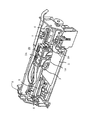
図1は、本発明の実施形態1に係るインクジェット式記録ヘッドの概略構成を示す分解斜視図であり、図2は、図1の平面図及びそのA−A′断面図である。図示するように、流路形成基板10は、本実施形態では面方位(110)のシリコン単結晶基板からなり、その一方の面には予め熱酸化により形成した二酸化シリコンからなる、厚さ0.5〜2μmの弾性膜50が形成されている。流路形成基板10には、隔壁11によって区画された複数の圧力発生室12がその幅方向に並設されている。また、流路形成基板10の圧力発生室12の長手方向外側の領域には連通部13が形成され、連通部13と各圧力発生室12とが、各圧力発生室12毎に設けられたインク供給路14を介して連通されている。なお、連通部13は、後述する保護基板のリザーバ部と連通して各圧力発生室12の共通のインク室となるリザーバの一部を構成する。インク供給路14は、圧力発生室12よりも狭い幅で形成されており、連通部13から圧力発生室12に流入するインクの流路抵抗を一定に保持している。
Hereinafter, the present invention will be described in detail based on embodiments.
(Embodiment 1)
FIG. 1 is an exploded perspective view showing a schematic configuration of an ink jet recording head according to
また、流路形成基板10の開口面側には、各圧力発生室12のインク供給路14とは反対側の端部近傍に連通するノズル開口21が穿設されたノズルプレート20が、後述するマスク膜52を介して接着剤や熱溶着フィルム等によって固着されている。なお、ノズルプレート20は、例えば、ガラスセラミックス、シリコン単結晶基板又はステンレス鋼などからなる。
Further, a
一方、流路形成基板10の開口面とは反対側には、上述したように、二酸化シリコンからなり厚さが例えば、約1.0μmの弾性膜50が形成され、この弾性膜50上には、例えば、酸化ジルコニウム(ZrO2)等からなり厚さが例えば、約0.4μmの絶縁体膜55が積層形成されている。また、絶縁体膜55上には、厚さが例えば、約0.1〜0.2μmの下電極膜60と、厚さが例えば、約0.5〜5μmの圧電体層70と、厚さが例えば、約0.05μmの上電極膜80とからなる圧電素子300が形成されている。すなわち、本発明では、振動板が酸化膜を有し、圧電素子300はこの酸化膜上に形成されている。なお、一般的には、圧電素子300の何れか一方の電極を共通電極とし、他方の電極及び圧電体層70を各圧力発生室12毎にパターニングして構成する。本実施形態では、下電極膜60を圧電素子300の共通電極とし、上電極膜80を圧電素子300の個別電極としているが、駆動回路や配線の都合でこれを逆にしても支障はない。また、ここでは、圧電素子300と当該圧電素子300の駆動により変位が生じる振動板とを合わせてアクチュエータ装置と称する。
On the other hand, an
また、このような各圧電素子300の上電極膜80には、例えば、金(Au)等からなるリード電極90がそれぞれ接続され、このリード電極90を介して各圧電素子300に選択的に電圧が印加されるようになっている。
In addition, a
また、本実施形態では、圧電素子300の各層及びリード電極90のパターン領域は、下電極膜60の接続部60a及びリード電極90の接続部90aに対向する領域を除いて、絶縁材料からなる絶縁膜95によって覆われている。すなわち、この接続部60a,90aを除いて、下電極膜60、圧電体層70、上電極膜80及びリード電極90の表面が、絶縁膜95によって覆われている。これにより、圧電体層70の水分(湿気)に起因する破壊が防止される。なお、絶縁膜95の材料としては、無機絶縁材料であれば、特に限定されず、例えば、酸化アルミニウム(Al2O3)、五酸化タンタル(Ta2O5)等が挙げられるが、特に、酸化アルミニウム(Al2O3)を用いるのが好ましい。
In the present embodiment, each layer of the
このような圧電素子300が形成された流路形成基板10には、圧電素子300に対向する領域に、圧電素子300を保護するための圧電素子保持部31を有する保護基板30が、接着剤等によって接合されている。なお、圧電素子保持部31は、圧電素子300の運動を阻害しない程度の空間を確保できればよく、当該空間は密封されていても、密封されていなくてもよい。また、保護基板30には、連通部13に対向する領域にリザーバ部32が設けられており、このリザーバ部32は、上述したように、流路形成基板10の連通部13と連通されて各圧力発生室12の共通のインク室となるリザーバ100を構成している。また、保護基板30の圧電素子保持部31とリザーバ部32との間の領域には、保護基板30を厚さ方向に貫通する貫通孔33が設けられ、この貫通孔33内に下電極膜60の一部及びリード電極90の先端部が露出され、これら下電極膜60及びリード電極90には、図示しないが、駆動ICから延設される接続配線の一端が接続される。
In the flow
保護基板30としては、流路形成基板10の熱膨張率と略同一の材料、例えば、ガラス、セラミック材料等を用いることが好ましく、本実施形態では、流路形成基板10と同一材料のシリコン単結晶基板を用いて形成した。
As the
保護基板30上には、封止膜41及び固定板42とからなるコンプライアンス基板40が接合されている。ここで、封止膜41は、剛性が低く可撓性を有する材料(例えば、厚さが6μmのポリフェニレンサルファイド(PPS)フィルム)からなり、この封止膜41によってリザーバ部32の一方面が封止されている。また、固定板42は、金属等の硬質の材料(例えば、厚さが30μmのステンレス鋼(SUS)等)で形成される。この固定板42のリザーバ100に対向する領域は、厚さ方向に完全に除去された開口部43となっているため、リザーバ100の一方面は可撓性を有する封止膜41のみで封止されている。
On the
このような本実施形態のインクジェット式記録ヘッドでは、図示しない外部インク供給手段からインクを取り込み、リザーバ100からノズル開口21に至るまで内部をインクで満たした後、駆動ICからの記録信号に従い、圧力発生室12に対応するそれぞれの下電極膜60と上電極膜80との間に電圧を印加し、弾性膜50、下電極膜60及び圧電体層70をたわみ変形させることにより、各圧力発生室12内の圧力が高まりノズル開口21からインク滴が吐出する。
In such an ink jet recording head of this embodiment, after taking ink from an external ink supply means (not shown) and filling the interior from the
以下、インクジェット式記録ヘッドの製造方法について、図3〜図6を参照して説明する。なお、図3〜図6は、圧力発生室12の長手方向の断面図である。まず、図3(a)に示すように、シリコンウェハである流路形成基板用ウェハ110を約1100℃の拡散炉で熱酸化し、その表面に弾性膜50を構成する二酸化シリコン膜51を形成する。なお、本実施形態では、流路形成基板用ウェハ110として、膜厚が約625μmと比較的厚く剛性の高いシリコンウェハを用いている。
Hereinafter, a method for manufacturing the ink jet recording head will be described with reference to FIGS. 3 to 6 are cross-sectional views of the
次いで、図3(b)に示すように、弾性膜50(二酸化シリコン膜51)上に、酸化ジルコニウムからなる絶縁体膜55を形成する。具体的には、弾性膜50(二酸化シリコン膜51)上に、例えば、スパッタリング法等によりジルコニウム(Zr)層を形成後、このジルコニウム層を、例えば、500〜1200℃の拡散炉で熱酸化することにより酸化ジルコニウム(ZrO2)からなる絶縁体膜55を形成する。
Next, as shown in FIG. 3B, an
次いで、図3(c)に示すように、白金(Pt)、イリジウム(Ir)等からなる下電極膜60を絶縁体膜55の全面に形成後、所定形状にパターニングする。例えば、本実施形態では、イリジウムからなる膜と、白金からなる膜とをスパッタリング法により積層し、積層された複数の膜を所定形状にパターニングすることにより下電極膜60とした。
Next, as shown in FIG. 3C, a
次に、図3(d)に示すように、下電極膜60及び絶縁体膜55上に、チタン(Ti)を、例えば、スパッタリング法等によって塗布することにより所定の厚さの種チタン層65を形成する。次に、この種チタン層65上に、圧電材料、本実施形態では、チタン酸ジルコン酸鉛(PZT)からなる圧電体層70を形成する。なお、本実施形態では、金属有機物を触媒に溶解・分散したいわゆるゾルを塗布乾燥してゲル化し、さらに高温で焼成することで金属酸化物からなる圧電体層70を得る、いわゆるゾル−ゲル法を用いて圧電体層70を形成した。また、圧電体層70の製造方法は、ゾル−ゲル法に限定されず、例えば、MOD(Metal-Organic Decomposition)法等を用いてもよい。
Next, as shown in FIG. 3D, titanium (Ti) is applied on the
圧電体層70の形成手順の一例としては、まず、図4(a)に示すように、種チタン層65上にPZT前駆体膜である圧電体前駆体膜71を成膜する。すなわち、流路形成基板用ウェハ110上に金属有機化合物を含むゾル(溶液)を塗布する。次いで、圧電体前駆体膜71を、所定温度に加熱して一定時間乾燥させ、ゾルの溶媒を蒸発させることで圧電体前駆体膜71を乾燥させる。さらに、大気雰囲気下において一定の温度で一定時間、圧電体前駆体膜71を脱脂する。なお、ここで言う脱脂とは、ゾル膜の有機成分を、例えば、NO2、CO2、H2O等として離脱させることである。
As an example of the procedure for forming the
そして、このような塗布・乾燥・脱脂の工程を、所定回数、例えば、2回繰り返すことで、図4(b)に示すように、圧電体前駆体膜71を所定厚に形成し、この圧電体前駆体膜71を拡散炉等で加熱処理することによって結晶化させて圧電体膜72を形成する。すなわち、圧電体前駆体膜71を焼成することで種チタン層65を核として結晶が成長して圧電体膜72が形成される。なお、焼成温度は、650〜850℃程度であることが好ましく、例えば、本実施形態では、約700℃で30分間、圧電体前駆体膜71を焼成して圧電体膜72を形成した。なお、このような条件で形成した圧電体膜72の結晶は(100)面に優先配向する。
Then, by repeating such coating, drying, and degreasing processes a predetermined number of times, for example, twice, as shown in FIG. 4B, a
さらに、上述した塗布・乾燥・脱脂・焼成の工程を、複数回繰り返すことにより、図4(c)に示すように、例えば、5層の圧電体膜72からなる所定厚さの圧電体層70を形成する。
Further, by repeating the above-described coating, drying, degreasing, and firing steps a plurality of times, as shown in FIG. 4C, for example, a
なお、圧電体層70の材料としては、例えば、チタン酸ジルコン酸鉛(PZT)等の強誘電性圧電性材料に、ニオブ、ニッケル、マグネシウム、ビスマス又はイットリウム等の金属を添加したリラクサ強誘電体等を用いてもよい。その組成は、圧電素子の特性、用途等を考慮して適宜選択すればよいが、例えば、PbTiO3(PT)、PbZrO3(PZ)、Pb(ZrxTi1−x)O3(PZT)、Pb(Mg1/3Nb2/3)O3−PbTiO3(PMN−PT)、Pb(Zn1/3Nb2/3)O3−PbTiO3(PZN−PT)、Pb(Ni1/3Nb2/3)O3−PbTiO3(PNN−PT)、Pb(In1/2Nb1/2)O3−PbTiO3(PIN−PT)、Pb(Sc1/3Ta2/3)O3−PbTiO3(PST−PT)、Pb(Sc1/3Nb2/3)O3−PbTiO3(PSN−PT)、BiScO3−PbTiO3(BS−PT)、BiYbO3−PbTiO3(BY−PT)等が挙げられる。
As a material of the
このように圧電体層70を形成した後は、図5(a)に示すように、例えば、イリジウム(Ir)からなる上電極膜80を流路形成基板用ウェハ110の全面に形成する。このとき、本発明では、スパッタリング法、例えば、DC又はRFスパッタリング法によって、上電極膜80を、厚さが30〜100(nm)であって応力が0.3〜2.0(GPa)であり、且つ比抵抗が2.0(×10−7Ω・m)以下であるように形成した。なおここでは、引張り方向の応力を正の値で示し、圧縮方向の応力を負の値で示す。
After the
上電極膜80の応力及び比抵抗が上記のような値となるようにするためには、上電極膜80を成膜する際のスパッタリング圧力を0.4〜1.5(Pa)とし、上電極膜80を成膜する際の温度、すなわち、流路形成基板用ウェハ110の加熱温度を、25℃(常温)〜250℃の範囲とする。これにより、上電極膜80を30〜100(nm)の厚さで形成することによって、上電極膜80の応力を所望の値とすることができ、また比抵抗も所望の値とすることができる。また、上電極膜80を成膜する際の温度を25℃(常温)〜250℃の範囲とすることで、上電極膜80を形成する際の熱による圧電体層70のダメージを防止して圧電体層70の圧電特性を良好に維持することができる。
In order to make the stress and specific resistance of the
また、スパッタリング法によって上電極膜を成膜する際のパワー密度は、特に限定されないが、3〜30(kW/m2)の範囲とすることが好ましい。これにより、応力及び比抵抗を上記の値である上電極膜80をより確実に形成することができる。
Moreover, the power density at the time of forming an upper electrode film | membrane by sputtering method is although it does not specifically limit, It is preferable to set it as the range of 3-30 (kW / m < 2 >). Thereby, the
なお、上記の条件で上電極膜80を成膜することで、上電極膜80の比抵抗を2.0(×10−7Ω・m)以下とすることができるが、上電極膜80の比抵抗は、例えば、スパッタリング法によって上電極膜80を成膜する際に導入されるアルゴン(Ar)等のガス圧を変化させることによっても調整することができる。
The specific resistance of the
このように上電極膜80を形成した後は、図5(b)に示すように、圧電体層70及び上電極膜80を、各圧力発生室12に対向する領域にパターニングして圧電素子300を形成する。また、圧電素子300を形成した後は、図5(c)に示すように、流路形成基板用ウェハ110の全面に亘って、例えば、金(Au)等からなる金属層91を形成し、その後、例えば、レジスト等からなるマスクパターン(図示なし)を介して金属層91を圧電素子300毎にパターニングすることによってリード電極90を形成する。
After the
次に、図5(d)に示すように、例えば、酸化アルミニウム(Al2O3)からなる絶縁膜95を形成する。すなわち、絶縁膜95を流路形成基板10の全面に形成し、その後、この絶縁膜95をイオンミリング等のドライエッチングによってパターニングして下電極膜60の接続部60a及びリード電極90の接続部90aとなる領域等を露出させる。
Next, as shown in FIG. 5D, an insulating
次に、図6(a)に示すように、流路形成基板用ウェハ110の圧電素子300側に、シリコンウェハであり複数の保護基板30となる保護基板用ウェハ130を接合する。なお、この保護基板用ウェハ130は、例えば、400μm程度の厚さを有するため、保護基板用ウェハ130を接合することによって流路形成基板用ウェハ110の剛性は著しく向上することになる。
Next, as shown in FIG. 6A, a
次いで、図6(b)に示すように、流路形成基板用ウェハ110をある程度の厚さとなるまで研磨した後、さらにフッ硝酸によってウェットエッチングすることにより流路形成基板用ウェハ110を所定の厚みにする。例えば、本実施形態では、約70μm厚になるように流路形成基板用ウェハ110をエッチング加工した。次いで、図6(c)に示すように、流路形成基板用ウェハ110上に、例えば、窒化シリコン(SiN)からなるマスク膜52を新たに形成し、所定形状にパターニングする。そして、このマスク膜52を介して流路形成基板用ウェハ110を異方性エッチングすることにより、図6(d)に示すように、流路形成基板用ウェハ110に圧力発生室12、連通部13及びインク供給路14等を形成する。
Next, as shown in FIG. 6B, after the flow path forming
なお、その後は、流路形成基板用ウェハ110及び保護基板用ウェハ130の外周縁部の不要部分を、例えば、ダイシング等により切断することによって除去する。そして、流路形成基板用ウェハ110の保護基板用ウェハ130とは反対側の面にノズル開口21が穿設されたノズルプレート20を接合すると共に、保護基板用ウェハ130にコンプライアンス基板40を接合し、流路形成基板用ウェハ110等を図1に示すような一つのチップサイズの流路形成基板10等に分割することによって、本実施形態のインクジェット式記録ヘッドとする。
After that, unnecessary portions of the outer peripheral edge portions of the flow path forming
以上説明したように、本発明では、圧電素子300を構成する上電極膜80を、その厚さが30〜100(nm)であって応力が0.3〜2.0(GPa)であり、且つ比抵抗が2.0(×10−7Ω・m)以下であるように形成するようにした。これにより、上電極膜80と圧電体層70との密着性が向上して上電極膜80の剥離が防止され、且つ圧電体層70の電気的特性が低下することもない。すなわち、上電極膜80は、圧縮方向の応力が強いと剥離し易く、一方、引張り方向の応力が強いと剥離し難いが圧電体層70の分極特性が低下する傾向にあるが、上述した条件で上電極膜80を形成することで、圧電体層70の電気的特性と上電極膜80の密着性とが何れも良好な圧電素子300が得られる。ちなみに、比抵抗は、2.0(×10−7Ω・m)以下であれば下限値は特に限定されないが、好ましくは、1.59(×10−7Ω・m)以上であることが好ましい。
As described above, in the present invention, the
さらに、このような上電極膜80はその膜質も向上し表面が実質的に凹凸のない平滑な面となるため、絶縁膜95もこの上電極膜80上に均一な厚さで良好に形成され、その結果、絶縁膜95の剥離も防止される。したがって、変位特性及び耐久性に優れたアクチュエータ装置が得られ、長期に亘って良好な印刷品質を維持可能なインクジェット式記録ヘッドを実現することができる。
Further, since the
ここで、下記表1に示す成膜条件で上電極膜であるIr膜を成膜した実施例1〜8及び比較例1〜15のアクチュエータ装置を作製し、これら各実施例及び比較例のアクチュエータ装置における上電極膜の最大反り方向の応力を測定すると、アクチュエータ装置の変位量、及び上電極膜(TE)の圧電体層との密着力を評価した。その結果を、下記表1に併せて示す。 Here, actuator devices of Examples 1 to 8 and Comparative Examples 1 to 15 in which an Ir film as an upper electrode film was formed under the film forming conditions shown in Table 1 below were prepared, and actuators of these Examples and Comparative Examples When the stress in the maximum warping direction of the upper electrode film in the device was measured, the displacement amount of the actuator device and the adhesion force between the upper electrode film (TE) and the piezoelectric layer were evaluated. The results are also shown in Table 1 below.
なお、アクチュエータ装置の変位量がおよそ210(nm)以下であると上記液体噴射ヘッドの構造においてインクの吐出特性に影響を及ぼす。このため、アクチュエータの変位量は、変位量は210(nm)以上であれば「良好」と評価し、210(nm)より小さい場合には「低下」(不良)と評価した。また、上電極膜(TE)の圧電体層との密着力は、アクチュエータ装置が作製された段階で上電極膜の状態を観察し、上電極膜の剥離の有無及び圧電体層との上電極膜との間の空間の有無によって評価した。すなわち、上記剥離及び空間が存在すれば「低下」(不良)と評価し、存在しなければ「良好」と評価した。 If the displacement amount of the actuator device is approximately 210 (nm) or less, the ink ejection characteristics are affected in the structure of the liquid ejecting head. For this reason, the displacement amount of the actuator was evaluated as “good” when the displacement amount was 210 (nm) or more, and was evaluated as “decreased” (defective) when it was smaller than 210 (nm). Further, the adhesion force of the upper electrode film (TE) to the piezoelectric layer is determined by observing the state of the upper electrode film at the stage where the actuator device is manufactured, whether the upper electrode film is peeled off, and the upper electrode with the piezoelectric layer. The evaluation was based on the presence or absence of a space between the membranes. That is, if the above peeling and space exist, it was evaluated as “decreased” (bad), and if not present, it was evaluated as “good”.

上記表1に示すように、実施例1〜8のアクチュエータ装置では、変位量及びTE密着力は何れも「良好」と評価されたが、比較例1〜15のアクチュエータ装置では、変位量又はTE密着力の少なくとも一方が「低下」と評価されている。この結果から明らかなように、本発明よれば、上電極膜80と圧電体層70との密着性を向上して上電極膜80の剥離を防止でき、且つ圧電体層70の電気的特性も良好に維持することができる。
As shown in Table 1 above, in the actuator devices of Examples 1 to 8, the displacement amount and the TE adhesion force were both evaluated as “good”, but in the actuator devices of Comparative Examples 1 to 15, the displacement amount or TE At least one of the adhesion forces is evaluated as “decreased”. As is apparent from the results, according to the present invention, the adhesion between the
また、上記各実施例及び比較例のアクチュエータから任意に選択したアクチュエータ装置(実施例4及び比較例2のアクチュエータ装置)における圧電体層であるPZT薄膜の残留分極(2Pr)を調べた結果を下記表2に示す。なお、下記表2には、Ir成膜条件、Ir応力、Ir比抵抗及びアクチュエータ装置の変位量を併せて示す。また、図7に実施例及び比較例のアクチュエータ装置におけるPZT薄膜(圧電体層)のヒステリシス曲線を示す。 Further, the results of examining the remanent polarization (2Pr) of the PZT thin film, which is a piezoelectric layer, in the actuator device arbitrarily selected from the actuators of the above-described examples and comparative examples (actuator devices of Example 4 and Comparative Example 2) are as follows. It shows in Table 2. Table 2 below also shows the Ir film forming conditions, Ir stress, Ir specific resistance, and displacement of the actuator device. FIG. 7 shows hysteresis curves of the PZT thin film (piezoelectric layer) in the actuator devices of the example and the comparative example.
上記表2に示すように、実施例のアクチュエータ装置では、PZT薄膜の残留分極(2Pr)とアクチュエータの変位量とは、共に良好な値を示しているが、比較例のアクチュエータ装置では、これらの値は、実施例のアクチュエータ装置に比べて何れも低くなっていた。また、図7に示すPZT薄膜のヒステリシス曲線からも、実施例のアクチュエータ装置の方が、比較例に比べて分極強度が大きいことが分かる。 As shown in Table 2 above, in the actuator device of the example, both the remanent polarization (2Pr) of the PZT thin film and the displacement amount of the actuator show good values, but in the actuator device of the comparative example, these values are The values were all lower than that of the actuator device of the example. Also, from the hysteresis curve of the PZT thin film shown in FIG. 7, it can be seen that the actuator device of the example has higher polarization strength than the comparative example.
なお、上記表2に示した実施例は、スパッタ圧力(Pa)が0.4(Pa)としたものであるが、勿論、スパッタ圧力は0.4〜1.5(Pa)の範囲とすればよい。また、温度は250℃であるが、25〜250℃であればよい。これによりPZT薄膜の残留分極(2Pr)は、上記比較例よりも確実に高い数値となる。 In the examples shown in Table 2 above, the sputtering pressure (Pa) is 0.4 (Pa). Of course, the sputtering pressure is in the range of 0.4 to 1.5 (Pa). That's fine. Moreover, although temperature is 250 degreeC, it should just be 25-250 degreeC. As a result, the remanent polarization (2Pr) of the PZT thin film is reliably higher than that of the comparative example.
また、上電極膜80の材料としては、イリジウム(Ir)が用いていれていればよい。上電極膜80の具体的な態様としては、イリジウム(Ir)の単層からなるものに限定されず、イリジウム(Ir)を主成分とする合金層からなるものであってもよい。また、イリジウム(Ir)層又はイリジウム(Ir)を主成分とする合金層の圧電体層70と接する面とは反対側の面に他の層を積層して上電極膜80としてもよい。
Moreover, as a material of the
(他の実施形態)
以上、本発明の実施形態について説明したが、本発明は、上述の実施形態に限定されるものではない。
(Other embodiments)
As mentioned above, although embodiment of this invention was described, this invention is not limited to the above-mentioned embodiment.
また、これら各実施形態のインクジェット式記録ヘッドは、インクカートリッジ等と連通するインク流路を具備する記録ヘッドユニットの一部を構成して、インクジェット式記録装置に搭載される。図8は、そのインクジェット式記録装置の一例を示す概略図である。図8に示すように、インクジェット式記録ヘッドを有する記録ヘッドユニット1A及び1Bは、インク供給手段を構成するカートリッジ2A及び2Bが着脱可能に設けられ、この記録ヘッドユニット1A及び1Bを搭載したキャリッジ3は、装置本体4に取り付けられたキャリッジ軸5に軸方向移動自在に設けられている。この記録ヘッドユニット1A及び1Bは、例えば、それぞれブラックインク組成物及びカラーインク組成物を吐出するものとしている。
In addition, the ink jet recording heads of these embodiments constitute a part of a recording head unit having an ink flow path communicating with an ink cartridge or the like, and are mounted on the ink jet recording apparatus. FIG. 8 is a schematic view showing an example of the ink jet recording apparatus. As shown in FIG. 8, in the
そして、駆動モータ6の駆動力が図示しない複数の歯車およびタイミングベルト7を介してキャリッジ3に伝達されることで、記録ヘッドユニット1A及び1Bを搭載したキャリッジ3はキャリッジ軸5に沿って移動される。一方、装置本体4にはキャリッジ軸5に沿ってプラテン8が設けられており、図示しない給紙ローラなどにより給紙された紙等の記録媒体である記録シートSがプラテン8上を搬送されるようになっている。
The driving force of the driving
なお、上述した実施形態1では、液体噴射ヘッドの一例としてインクジェット式記録ヘッドを挙げて説明したが、本発明は広く液体噴射ヘッド全般を対象としたものであり、インク以外の液体を噴射する液体噴射ヘッドにも勿論適用することができる。その他の液体噴射ヘッドとしては、例えば、プリンタ等の画像記録装置に用いられる各種の記録ヘッド、液晶ディスプレー等のカラーフィルタの製造に用いられる色材噴射ヘッド、有機ELディスプレー、FED(電界放出ディスプレー)等の電極形成に用いられる電極材料噴射ヘッド、バイオchip製造に用いられる生体有機物噴射ヘッド等が挙げられる。さらに、本発明は、液体噴射ヘッドに利用されるアクチュエータ装置だけでなく、例えば、センサ等、他のあらゆる装置に搭載されるアクチュエータ装置にも適用できることは言うまでもない。 In the first embodiment described above, the ink jet recording head has been described as an example of the liquid ejecting head. However, the present invention is widely applied to all liquid ejecting heads, and is a liquid ejecting liquid other than ink. Of course, the present invention can also be applied to an ejection head. Other liquid ejecting heads include, for example, various recording heads used in image recording apparatuses such as printers, color material ejecting heads used in the manufacture of color filters such as liquid crystal displays, organic EL displays, and FEDs (field emission displays). Examples thereof include an electrode material ejection head used for electrode formation, a bioorganic matter ejection head used for biochip production, and the like. Further, it goes without saying that the present invention can be applied not only to an actuator device used for a liquid ejecting head but also to an actuator device mounted on any other device such as a sensor.
10 流路形成基板、 12 圧力発生室、 13 連通部、 14 インク供給路、 20 ノズルプレート、 21 ノズル開口、 30 保護基板、 31 圧電素子保持部、 32 リザーバ部、 40 コンプライアンス基板、 60 下電極膜、 65 種チタン層、 70 圧電体層、 80 上電極膜、 90 リード電極、 95 絶縁膜、 100 リザーバ、 300 圧電素子
DESCRIPTION OF
Claims (6)
A liquid ejecting apparatus comprising the liquid ejecting head according to claim 5.
Priority Applications (2)
| Application Number | Priority Date | Filing Date | Title |
|---|---|---|---|
| JP2006192068A JP2007073931A (en) | 2005-08-09 | 2006-07-12 | Actuator equipment, manufacturing method thereof, and liquid injection head and liquid injection equipment |
| US11/501,032 US7725996B2 (en) | 2005-08-09 | 2006-08-09 | Method for producing actuator device |
Applications Claiming Priority (2)
| Application Number | Priority Date | Filing Date | Title |
|---|---|---|---|
| JP2005230792 | 2005-08-09 | ||
| JP2006192068A JP2007073931A (en) | 2005-08-09 | 2006-07-12 | Actuator equipment, manufacturing method thereof, and liquid injection head and liquid injection equipment |
Publications (2)
| Publication Number | Publication Date |
|---|---|
| JP2007073931A true JP2007073931A (en) | 2007-03-22 |
| JP2007073931A5 JP2007073931A5 (en) | 2009-05-07 |
Family
ID=37776619
Family Applications (1)
| Application Number | Title | Priority Date | Filing Date |
|---|---|---|---|
| JP2006192068A Withdrawn JP2007073931A (en) | 2005-08-09 | 2006-07-12 | Actuator equipment, manufacturing method thereof, and liquid injection head and liquid injection equipment |
Country Status (2)
| Country | Link |
|---|---|
| US (1) | US7725996B2 (en) |
| JP (1) | JP2007073931A (en) |
Cited By (2)
| Publication number | Priority date | Publication date | Assignee | Title |
|---|---|---|---|---|
| JP2011142280A (en) * | 2010-01-09 | 2011-07-21 | Seiko Epson Corp | Actuator apparatus, method of manufacturing the same, method of manufacturing liquid injection head, and method of manufacturing liquid injection equipment |
| US8966729B2 (en) | 2010-03-10 | 2015-03-03 | Seiko Epson Corporation | Method for manufacturing piezoelectric actuator |
Families Citing this family (5)
| Publication number | Priority date | Publication date | Assignee | Title |
|---|---|---|---|---|
| JP2009170467A (en) * | 2008-01-10 | 2009-07-30 | Seiko Epson Corp | Manufacturing method of liquid spray head, and manufacturing method of actuator device |
| JP2009226728A (en) * | 2008-03-21 | 2009-10-08 | Seiko Epson Corp | Manufacturing method of liquid jet head and manufacturing method of piezoelectric element |
| EP2554980B1 (en) * | 2011-08-03 | 2014-06-25 | Nxp B.V. | Integrated circuit with sensor and method of manufacturing such an integrated circuit |
| US8866367B2 (en) | 2011-10-17 | 2014-10-21 | The United States Of America As Represented By The Secretary Of The Army | Thermally oxidized seed layers for the production of {001} textured electrodes and PZT devices and method of making |
| US9761785B2 (en) | 2011-10-17 | 2017-09-12 | The United States Of America As Represented By The Secretary Of The Army | Stylo-epitaxial piezoelectric and ferroelectric devices and method of manufacturing |
Family Cites Families (10)
| Publication number | Priority date | Publication date | Assignee | Title |
|---|---|---|---|---|
| JPH05286131A (en) | 1992-04-15 | 1993-11-02 | Rohm Co Ltd | Ink jet print head and production thereof |
| JP3387352B2 (en) | 1996-02-22 | 2003-03-17 | セイコーエプソン株式会社 | Ink jet recording head, ink jet recording apparatus using the same, and method of manufacturing ink jet recording head |
| JP3209082B2 (en) | 1996-03-06 | 2001-09-17 | セイコーエプソン株式会社 | Piezoelectric thin film element, method of manufacturing the same, and ink jet recording head using the same |
| JPH10264384A (en) | 1997-03-27 | 1998-10-06 | Seiko Epson Corp | Ink-jet type recording head, its manufacture, and piezoelectric element thereof |
| JPH1187791A (en) | 1997-09-02 | 1999-03-30 | Seiko Epson Corp | Piezoelectric element, ink jet recording head and manufacture thereof |
| JP3019845B1 (en) | 1997-11-25 | 2000-03-13 | セイコーエプソン株式会社 | Ink jet recording head and ink jet recording apparatus |
| JPH11344377A (en) * | 1998-06-02 | 1999-12-14 | Matsushita Electric Ind Co Ltd | Infrared detecting element and its manufacture |
| JP2004128492A (en) | 2002-09-13 | 2004-04-22 | Matsushita Electric Ind Co Ltd | Piezoelectric thin-film element and actuator using it, ink jet head and ink jet recording device |
| US7411339B2 (en) | 2003-11-28 | 2008-08-12 | Seiko Epson Corporation | Manufacturing method of actuator device and liquid jet apparatus provided with actuator device formed by manufacturing method of the same |
| JP4380310B2 (en) | 2003-12-08 | 2009-12-09 | セイコーエプソン株式会社 | Actuator device, liquid jet head, and liquid jet device |
-
2006
- 2006-07-12 JP JP2006192068A patent/JP2007073931A/en not_active Withdrawn
- 2006-08-09 US US11/501,032 patent/US7725996B2/en active Active
Cited By (2)
| Publication number | Priority date | Publication date | Assignee | Title |
|---|---|---|---|---|
| JP2011142280A (en) * | 2010-01-09 | 2011-07-21 | Seiko Epson Corp | Actuator apparatus, method of manufacturing the same, method of manufacturing liquid injection head, and method of manufacturing liquid injection equipment |
| US8966729B2 (en) | 2010-03-10 | 2015-03-03 | Seiko Epson Corporation | Method for manufacturing piezoelectric actuator |
Also Published As
| Publication number | Publication date |
|---|---|
| US7725996B2 (en) | 2010-06-01 |
| US20070033784A1 (en) | 2007-02-15 |
Similar Documents
| Publication | Publication Date | Title |
|---|---|---|
| JP5251031B2 (en) | Piezoelectric element, liquid ejecting head, liquid ejecting apparatus, sensor | |
| US7320163B2 (en) | Method of manufacturing an actuator device | |
| JP4296441B2 (en) | Method for manufacturing actuator device | |
| JP4333686B2 (en) | Actuator device, liquid jet head, and liquid jet device | |
| JP2006245247A (en) | Piezoelectric element and its fabrication process, liquid ejection head and its manufacturing process, and liquid ejector | |
| JP4501917B2 (en) | Actuator device and liquid jet head | |
| JP2007073931A (en) | Actuator equipment, manufacturing method thereof, and liquid injection head and liquid injection equipment | |
| JP2008284781A (en) | Liquid ejection head, its manufacturing process, and liquid ejector | |
| JP5310969B2 (en) | LAMINATED FILM MANUFACTURING METHOD, ACTUATOR DEVICE MANUFACTURING METHOD, ACTUATOR DEVICE, LIQUID EJECTING HEAD, AND LIQUID EJECTING DEVICE | |
| JP4858670B2 (en) | Method for manufacturing actuator device and liquid ejecting apparatus | |
| JP4877451B2 (en) | Piezoelectric element manufacturing method and liquid jet head | |
| JP2007048816A (en) | Actuator apparatus, manufacturing method thereof, liquid injection head, and liquid injection apparatus | |
| JP2007173604A (en) | Method of manufacturing piezoelectric element and method of manufacturing liquid jetting head | |
| KR100816169B1 (en) | Method for producing actuator device, actuator device, liquid-jet head and liquid-jet apparatus | |
| JP5201304B2 (en) | Method for manufacturing actuator device and method for manufacturing liquid jet head | |
| JP5578311B2 (en) | Liquid ejecting head, liquid ejecting apparatus, and method of manufacturing liquid ejecting head | |
| JP5376107B2 (en) | Piezoelectric element and manufacturing method thereof, actuator device, liquid jet head, and liquid jet device | |
| JP2006245248A (en) | Piezoelectric element and its fabrication process, liquid ejection head and its manufacturing process, and liquid ejector | |
| JP2007035883A (en) | Actuator device, its manufacturing method, and head and device for liquid injection | |
| JP2009226728A (en) | Manufacturing method of liquid jet head and manufacturing method of piezoelectric element | |
| JP2009076819A (en) | Actuator device, liquid jetting head and liquid jetting device | |
| JP2007173605A (en) | Method of manufacturing piezoelectric element and method of manufacturing liquid jetting head | |
| JP5024564B2 (en) | Actuator device and liquid jet head | |
| JP2005260003A (en) | Manufacturing method of actuator device and liquid injector | |
| JP2005209912A (en) | Piezoelectric element, and liquid injection head, as well as manufacturing method of piezoelectric element |
Legal Events
| Date | Code | Title | Description |
|---|---|---|---|
| A521 | Request for written amendment filed |
Free format text: JAPANESE INTERMEDIATE CODE: A523 Effective date: 20090312 |
|
| A621 | Written request for application examination |
Free format text: JAPANESE INTERMEDIATE CODE: A621 Effective date: 20090312 |
|
| A761 | Written withdrawal of application |
Free format text: JAPANESE INTERMEDIATE CODE: A761 Effective date: 20110121 |