JP2006527140A - Apparatus for supplying fluid into a syringe, syringe filling station and method for filling a syringe with fluid - Google Patents
Apparatus for supplying fluid into a syringe, syringe filling station and method for filling a syringe with fluid Download PDFInfo
- Publication number
- JP2006527140A JP2006527140A JP2006515209A JP2006515209A JP2006527140A JP 2006527140 A JP2006527140 A JP 2006527140A JP 2006515209 A JP2006515209 A JP 2006515209A JP 2006515209 A JP2006515209 A JP 2006515209A JP 2006527140 A JP2006527140 A JP 2006527140A
- Authority
- JP
- Japan
- Prior art keywords
- syringe
- fluid
- filling station
- reservoir
- pump
- Prior art date
- Legal status (The legal status is an assumption and is not a legal conclusion. Google has not performed a legal analysis and makes no representation as to the accuracy of the status listed.)
- Pending
Links
Images


Classifications
-
- B—PERFORMING OPERATIONS; TRANSPORTING
- B65—CONVEYING; PACKING; STORING; HANDLING THIN OR FILAMENTARY MATERIAL
- B65B—MACHINES, APPARATUS OR DEVICES FOR, OR METHODS OF, PACKAGING ARTICLES OR MATERIALS; UNPACKING
- B65B3/00—Packaging plastic material, semiliquids, liquids or mixed solids and liquids, in individual containers or receptacles, e.g. bags, sacks, boxes, cartons, cans, or jars
- B65B3/003—Filling medical containers such as ampoules, vials, syringes or the like
-
- B—PERFORMING OPERATIONS; TRANSPORTING
- B65—CONVEYING; PACKING; STORING; HANDLING THIN OR FILAMENTARY MATERIAL
- B65B—MACHINES, APPARATUS OR DEVICES FOR, OR METHODS OF, PACKAGING ARTICLES OR MATERIALS; UNPACKING
- B65B1/00—Packaging fluent solid material, e.g. powders, granular or loose fibrous material, loose masses of small articles, in individual containers or receptacles, e.g. bags, sacks, boxes, cartons, cans, or jars
- B65B1/04—Methods of, or means for, filling the material into the containers or receptacles
-
- A—HUMAN NECESSITIES
- A61—MEDICAL OR VETERINARY SCIENCE; HYGIENE
- A61M—DEVICES FOR INTRODUCING MEDIA INTO, OR ONTO, THE BODY; DEVICES FOR TRANSDUCING BODY MEDIA OR FOR TAKING MEDIA FROM THE BODY; DEVICES FOR PRODUCING OR ENDING SLEEP OR STUPOR
- A61M5/00—Devices for bringing media into the body in a subcutaneous, intra-vascular or intramuscular way; Accessories therefor, e.g. filling or cleaning devices, arm-rests
- A61M5/178—Syringes
- A61M5/1782—Devices aiding filling of syringes in situ
Abstract
Description
本発明は、一般的にはシリンジ充填の分野に関し、特に蠕動シリンジ充填のための方法および装置に関する。 The present invention relates generally to the field of syringe filling, and more particularly to a method and apparatus for peristaltic syringe filling.
多くの医療処置では、シリンジ(注射器)を使用して流体を患者内に注入することが必要である。特に、CT注射器等の医療流体注入システムは、1または複数のシリンジを使用して、測定されたある量の流体を患者内へ注入する。シリンジを使用して流体を注入する前に、最初に流体をシリンジに充填しなければならない。ときには、シリンジの充填が不正確であったり、不便であったり、融通が利かなかったりする場合がある。 In many medical procedures, it is necessary to inject fluid into a patient using a syringe. In particular, medical fluid injection systems, such as CT syringes, use a syringe or syringes to inject a measured amount of fluid into a patient. Before using a syringe to inject fluid, the fluid must first be filled into the syringe. Sometimes the filling of the syringe is inaccurate, inconvenient, or inconvenient.
充填済みのシリンジを得る1つの方法は、所望の流体が予め充填されているシリンジを購入することである。しかしながら、この方法には幾つかの欠点がある。第1に、所望の流体が予め充填されたシリンジは簡単に入手できない場合がある。第2に、シリンジが入手できたとしても、シリンジが所望量の流体を有していない場合もある。これらの理由および他の理由から、予め充填されたシリンジは望ましいとはいえない。 One way to obtain a prefilled syringe is to purchase a syringe that is pre-filled with the desired fluid. However, this method has several drawbacks. First, syringes pre-filled with the desired fluid may not be readily available. Second, even if a syringe is available, the syringe may not have the desired amount of fluid. For these and other reasons, prefilled syringes are not desirable.
シリンジを充填する他の方法としては、チューブを介して供給リザーバに空のシリンジを接続することを挙げることができる。シリンジプランジャはシリンジバレルから手で引き出される。プランジャが引き出されると、リザーバ内の流体がシリンジ内に導入される。この方法は、流体のタイプやシリンジに予め充填される量に関して大きな自由度を与える。 Another method of filling the syringe can include connecting an empty syringe to the supply reservoir via a tube. The syringe plunger is manually pulled out of the syringe barrel. When the plunger is withdrawn, the fluid in the reservoir is introduced into the syringe. This method gives great freedom with respect to the type of fluid and the amount prefilled in the syringe.
ここで、オペレータは、所望量の流体がシリンジへと移された時期を決定するためにシリンジ内に入った流体の量を “じっと見つめ”なければならない。ここで、移される流体の精度は、オペレータの技能および注意力に依存する。また、空気がチューブ内に捕捉されるため、シリンジを完全に満たすことが難しいかもしれない。また、必要な真空を形成して流体をシリンジ内に導入することが難しいかもしれない。更に、双方にバレル内に流体を導入すると、シリンジを充填するためにリザーバ全体が利用されないため、シリンジ内が汚染される可能性がある。 Here, the operator must “see” the amount of fluid that has entered the syringe to determine when the desired amount of fluid has been transferred to the syringe. Here, the accuracy of the fluid transferred depends on the skill and attention of the operator. Also, it may be difficult to completely fill the syringe because air is trapped in the tube. It may also be difficult to create the necessary vacuum and introduce the fluid into the syringe. Furthermore, if fluid is introduced into the barrel on both sides, the entire reservoir may not be utilized to fill the syringe, which may contaminate the syringe.
1つの他の実施形態において、本発明は、実質的に正確な量の流状媒体をシリンジに充填することができるシリンジ充填ステーションである。また、その充填ステーションは、片手で簡単に操作できる完全密閉型のシステムであっても良い。また、その充填ステーションは、造影剤やフラッシング流体等の多種多様な流体と共に使用されても良い。 In one other embodiment, the present invention is a syringe filling station that can fill a syringe with a substantially accurate amount of fluid medium. The filling station may also be a fully enclosed system that can be easily operated with one hand. The filling station may also be used with a wide variety of fluids such as contrast agents and flushing fluids.
本発明の1つの他の実施形態において、シリンジ充填ステーションは、リザーバ取付部と、流体供給システムと、シリンジ保持ガイドと、流体をリザーバからシリンジへと移動させるポンプとを備えている。一実施形態において、その流体供給システムは、充填ステーション内に挿入可能で且つリザーバからシリンジへと向かう流体通路を形成する無菌消耗カートリッジであっても良い。また、流体供給システムは、一端をスパイクに取り付けられ、他端をカニューレに取り付けられた可撓性チューブを含んでいてもよい。スパイクは、リザーバ内に挿入することができ、カニューレは、少なくとも一部がシリンジ内に挿入可能である。チューブは、シリンジ充填ステーションを貫通することができ、ポンプの近傍に配置することができる。一実施形態においては、ポンプの回転により流体がチューブを通じて移動する。 In one other embodiment of the present invention, the syringe filling station includes a reservoir mount, a fluid supply system, a syringe holding guide, and a pump that moves fluid from the reservoir to the syringe. In one embodiment, the fluid supply system may be a sterile consumable cartridge that is insertable into the filling station and forms a fluid passageway from the reservoir to the syringe. The fluid supply system may also include a flexible tube with one end attached to the spike and the other end attached to the cannula. The spike can be inserted into the reservoir and the cannula can be inserted at least partially into the syringe. The tube can penetrate the syringe filling station and can be placed in the vicinity of the pump. In one embodiment, fluid is moved through the tube by rotation of the pump.
また、シリンジ充填ステーションは、ユーザインタフェースを含んでも良い。一実施形態において、オペレータは、シリンジ内に導入される流体の量を指定するためにユーザインタフェースにコマンドを入力することができる。所望量の流体をシリンジに正確に充填するため、ユーザインタフェースは、ポンプ速度を制御するプロセッサに接続することができる。また、充填ステーションは、チューブ内の空気を検出したり、リザーバが空になったことを検出するようなセンサを有していても良い。センサは、プロセッサに信号を送信することができる。プロセッサは、センサから受けたデータに応じて特定の機能を実行するようにポンプに指示することができる。その結果、充填ステーションを使用して、所望量の流体をシリンジに正確且つ効率的に充填することができる。 The syringe filling station may also include a user interface. In one embodiment, the operator can enter a command into the user interface to specify the amount of fluid to be introduced into the syringe. In order to accurately fill the syringe with the desired amount of fluid, the user interface can be connected to a processor that controls the pump speed. The filling station may have a sensor that detects air in the tube and detects that the reservoir is empty. The sensor can send a signal to the processor. The processor can instruct the pump to perform a specific function in response to data received from the sensor. As a result, the filling station can be used to accurately and efficiently fill the syringe with the desired amount of fluid.
一実施形態においては、使い捨て可能な投与カートリッジが予め組み立てられた状態で利用可能であり、これにより、投与カートリッジをシリンジ充填ステーション内に簡単に位置決めして配置することができる。投与カートリッジは、リザーバとスパイクとの間およびカニューレとシリンジとの間で無菌または滅菌インタフェースが維持されるようにするのに役立つ。また、シリンジ充填ステーションは、シリンジがシリンジ保持ガイド内に挿入される際にオペレータがシリンジを観察することができる透明なプラスチック窓を有していても良い。結果として、シリンジ充填ステーションは、医療流体をシリンジに充填するための無菌または滅菌環境を与える。 In one embodiment, a disposable dosing cartridge is available pre-assembled, which allows the dosing cartridge to be easily positioned and positioned within the syringe filling station. The dosing cartridge serves to maintain a sterile or sterile interface between the reservoir and the spike and between the cannula and the syringe. Moreover, the syringe filling station may have a transparent plastic window through which an operator can observe the syringe when the syringe is inserted into the syringe holding guide. As a result, the syringe filling station provides a sterile or sterile environment for filling the syringe with medical fluid.
また、本発明は、シリンジ充填ステーションを使用する方法も含んでいる。本発明の一実施形態において、本発明は、a)リザーバを取り外し可能に受けるためのリザーバ取付部と、流体ポンプと、シリンジ保持ガイドとを有する充填ステーションを用意するステップと、b)突出部材と、カニューレと、可撓性チューブとを有する流体供給システムを用意するステップと、c)上記流体供給システムを上記充填ステーション内に取り付けて、上記リザーバ取付部から上記シリンジ保持ガイドへと向かう流体通路を形成するステップと、d)流体リザーバを上記リザーバ取付部に接続するステップと、e)上記カニューレの少なくとも一部がシリンジ内に部分的に挿入されるように、シリンジを上記保持ガイド内に挿入するステップと、f)流体を上記リザーバから上記シリンジへと圧送するステップとを含む。 The present invention also includes a method of using a syringe filling station. In one embodiment of the present invention, the present invention comprises: a) providing a filling station having a reservoir mount for removably receiving a reservoir, a fluid pump, and a syringe holding guide; b) a protruding member; Providing a fluid supply system having a cannula and a flexible tube; and c) mounting the fluid supply system in the filling station to provide a fluid passageway from the reservoir mount to the syringe holding guide. And d) connecting a fluid reservoir to the reservoir mount; and e) inserting a syringe into the holding guide such that at least a portion of the cannula is partially inserted into the syringe. And f) pumping fluid from the reservoir to the syringe.
したがって、特に、本発明は、流体をシリンジに充填するための効率的で且つ信頼できる装置および方法を提供する。本発明の他の目的、特徴、利点は、以下の本発明の詳細な説明および添付図面を鑑みれば、当業者にとって明らかである。 Thus, in particular, the present invention provides an efficient and reliable apparatus and method for filling a syringe with fluid. Other objects, features and advantages of the present invention will be apparent to those skilled in the art in view of the following detailed description of the invention and the accompanying drawings.
これまで一般的な言葉で本発明を説明してきたが、次に、添付される非限定的な図面を参照する。これらの図面は、必ずしも一定の比率で描かれていない。
以下、添付図面を参照しながら、本発明について更に十分に説明する。実際には、本発明は、多くの異なる形態で具現化されても良く、ここに示された実施形態に限定されるものと解釈されるべきではない。むしろ、これらの実施形態は単なる例示的な目的で与えられている。 The present invention will be described more fully hereinafter with reference to the accompanying drawings. Indeed, the invention may be embodied in many different forms and should not be construed as limited to the embodiments set forth herein; Rather, these embodiments are provided for exemplary purposes only.
一実施形態において、本発明は、選択された或いは所定の量の流体でシリンジを満たすことができるシリンジ充填ステーションである。そのステーションは、リザーバを受けるためのリザーバアウトレットと、シリンジを解放可能に受けて固定するためのシリンジ保持ガイドと、リザーバとシリンジとの間に流体通路を形成する流体供給システムと、流体をリザーバからシリンジへと移動させるためのポンプとを有していても良い。1つの好ましい実施形態において、シリンジ充填ステーションは、シリンジに供給される流体の量を入力して制御するためのユーザインタフェースを有している。 In one embodiment, the present invention is a syringe filling station that can fill a syringe with a selected or predetermined amount of fluid. The station includes a reservoir outlet for receiving the reservoir, a syringe holding guide for releasably receiving and securing the syringe, a fluid supply system that forms a fluid path between the reservoir and the syringe, and fluid from the reservoir. You may have the pump for moving to a syringe. In one preferred embodiment, the syringe filling station has a user interface for inputting and controlling the amount of fluid supplied to the syringe.
リザーバは、造影剤等の医療分野で有用な流体を収容することができる。“造影剤”という用語は、一般に、医療分野で一般的に使用され且つ患者内に注入することができ、患者が例えばX線走査されている間に患者の身体の選択された領域を強調して示すことができる任意の適当な媒体のことである。一般に、造影剤は、CTスキャン、MRI、超音波診断等の医学的な画像診断を行なうための撮像装置と共に使用される。注射器と共に使用できる他の媒体としては、生理食塩水媒体やフラッシング媒体等を挙げることができるが、これらに限定されない。幾つかの実施形態において、充填ステーションは、一般に最大で約100cpsの粘度を有するニュートン流体でシリンジを満たすのに特に役立つ。一般に、粘度は、約0.5から100cpsであり、好ましくは約1から50cpsである。 The reservoir can contain a fluid useful in the medical field such as a contrast medium. The term “contrast agent” is generally used in the medical field and can be injected into a patient, highlighting selected areas of the patient's body while the patient is being scanned, for example, by x-ray. Any suitable medium that can be indicated. In general, a contrast agent is used together with an imaging device for performing medical image diagnosis such as CT scan, MRI, and ultrasonic diagnosis. Other media that can be used with the syringe include, but are not limited to, saline media and flushing media. In some embodiments, the filling station is particularly useful for filling syringes with Newtonian fluids, which generally have a viscosity of up to about 100 cps. Generally, the viscosity is about 0.5 to 100 cps, preferably about 1 to 50 cps.
典型的な一実施形態において、本発明は、流体をシリンジ内に供給するための装置である。その装置は、流体を有するリザーバを取り外し可能に受けるためのリザーバ取付部と、シリンジを解放可能に固定するためのシリンジ保持ガイドと、リザーバとシリンジとの間に流体通路を形成する消耗投与カートリッジと、流体をリザーバから投与カートリッジを通じてシリンジ内へと圧送するためのポンプとを備えている。投与カートリッジは、リザーバ内に挿入するための突出部材と、突出部材に取り付けられる先端部を有する可撓性チューブと、少なくとも一部がシリンジ内へ挿入されるようになっている可撓性チューブの基端部に取り付けられるカニューレとを備えている。好ましくは、投与カートリッジは単一のカートリッジとして利用できる。この場合、突出部材、カニューレおよびスパイクは、充填ステーションに簡単に取り付けることができるように予め組み立てられている。 In one exemplary embodiment, the present invention is an apparatus for supplying fluid into a syringe. The apparatus includes a reservoir mounting portion for removably receiving a reservoir having fluid, a syringe holding guide for releasably fixing a syringe, and a consumable dosing cartridge that forms a fluid passage between the reservoir and the syringe. A pump for pumping fluid from the reservoir through the dosing cartridge and into the syringe. An administration cartridge includes a protruding member for insertion into a reservoir, a flexible tube having a tip attached to the protruding member, and a flexible tube at least partially inserted into a syringe. And a cannula attached to the proximal end. Preferably, the dosing cartridge is available as a single cartridge. In this case, the protruding member, cannula and spike are pre-assembled for easy attachment to the filling station.
他の典型的な実施形態において、本発明は、流状媒体を有するリザーバと、リザーバ内に挿入される突出部材を有する流体供給システムと、先端部を突出部材に取り付けられる可撓性チューブと、可撓性チューブの基端部に取り付けられるカニューレと、略細長い本体を有するシリンジであって、その吐出部位の近傍に通路が配置され、流体をリザーバからシリンジ内へと供給できるようにカニューレが上記通路内へと延びているシリンジと、流体をリザーバからシリンジへと圧送するポンプと、ポンプに動作可能に接続され、特定量の流体がシリンジへと送り込まれるようにポンプを制御できる制御ユニットとを備えている。 In another exemplary embodiment, the present invention includes a reservoir having a fluid medium, a fluid supply system having a protruding member inserted into the reservoir, a flexible tube having a tip attached to the protruding member, A cannula attached to the proximal end of the flexible tube and a syringe having a generally elongated body, the passage being disposed near the discharge site, and the cannula so that fluid can be supplied from the reservoir into the syringe. A syringe that extends into the passage, a pump that pumps fluid from the reservoir to the syringe, and a control unit that is operably connected to the pump and that can control the pump so that a specific amount of fluid is pumped into the syringe. I have.
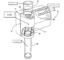
図1を参照すると、典型的なシリンジ(注射器)充填ステーションが広く参照符号10で示されている。シリンジ充填ステーション10は、流体ポンプ(図示せず)を収容するハウジング12と、リサーバ取付部17と、シリンジ保持ガイド50とを有していても良い。リザーバ取付部は、リザーバ15を取り外し可能に受けることができるようになっている。シリンジ25をガイドしてハウジング12内に位置決め固定するために、シリンジ保持ロックまたはガイドを使用することができる。幾つかの実施形態において、ハウジングは、オペレータが目で見て正確にシリンジを挿入して取り付けるのに役立つ透明観察窓11を含むことができる。透明観察窓11は、空気中に浮遊する汚染物質がハウジング内に配置されるシリンジの先端へと向かうことができないようにする部分的なバリアを形成している。流体供給システム(図示せず)は、リザーバからシリンジへと向かう流体経路を画定している。また、充填ステーションは、デジタルディスプレイ110と、例えば停止、ポーズ、パージライン、充填量等のシリンジ充填コマンドを入力するための接触制御部105とを有するユーザインタフェース106を含むことができる。
Referring to FIG. 1, a typical syringe filling station is indicated generally by the
図1に示されるシリンジ充填ステーションは、壁に装着でき或いは卓上に載置できる全体または一部が密閉されたユニットであっても良い。シリンジ充填ステーションは、無菌通路を通じて無菌流体を、無菌であっても良いシリンジの内部へと供給するための無菌機構または管路を備えている。 The syringe filling station shown in FIG. 1 may be a unit that can be mounted on a wall or placed on a table, either entirely or partially sealed. The syringe filling station includes a sterile mechanism or line for supplying sterile fluid through the sterile passage into the interior of the syringe, which may be sterile.
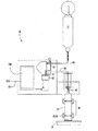
一実施形態において、充填ステーション10は、リサーバからシリンジへと流体を送る使い捨て可能な流体供給システムを含む。流体供給システムは、投与セットまたはカートリッジとも呼ばれており、毎日または他の特定の望ましい時に交換できる消耗カートリッジである。図2および図3を参照すると、シリンジ充填ステーションの概略図が示されている。流体供給システムは、例えばスパイク等の外側に突出する部材を含むがそれに限定されない突出部材35と、可撓性チューブ40と、カニューレ45とを有していても良い。スパイク35はリザーバ15内に挿入することができる。スパイクは可撓性チューブの上端または先端43に取り付けられる。チューブ40の下端部または基端部41はカニューレ45に取り付けられる。流体供給システムは、流体がリザーバからシリンジへと流通することができる通路を形成している。一実施形態において、流体投与セットは、リザーバまたはシリンジの手前でシリンジ充填ステーション内に取り付けられる。
In one embodiment, the filling
図2,3及び6に示されるように、スパイクはリザーバ内に挿入することができる。スパイクは入口点であり、それにより、流体は、投与セット内に流入することができ、シリンジへと移動することができる。スパイクは、流体がリザーバから圧送される際に空気がリザーバ内へと通過できるように通気可能である。通気孔を通じて空気がリザーバから出ることができないように、通気は一方向のみであっても良い。通気スパイクは、フィルターがかかっていてもかかっていなくても良い。スパイクは、例えば標準的なゴムコック付きのボトルまたはバック内に挿入することができる。スパイクは、スパイクロック機構または支持カラー37によって支持することができる。スパイク支持カラー37は、一般に、リザーバ15に隣接して配置される。スパイク支持カラーは、スパイクを支持するとともに、スパイクがリザーバ内で位置を変えたり或いはスパイクが誤ってリザーバから外れてしまうことを防止する。リザーバが使い果たされると、空になったリザーバをスパイクから簡単に取り外すことができるとともに、新しいリザーバをスパイクに取り付けて接続することができる。この場合、たとえあったとしても、スパイクの物理的な操作は僅かである。その結果、汚染物質を減らすこと、或いは制限することができ、それにより、シリンジ充填ステーションはシリンジ充填のための無菌環境を与える。
As shown in FIGS. 2, 3 and 6, the spike can be inserted into the reservoir. The spike is the entry point so that fluid can flow into the dosing set and travel to the syringe. The spike can be vented so that air can pass into the reservoir as fluid is pumped from the reservoir. Ventilation may be unidirectional so that air cannot exit the reservoir through the vent. The ventilation spike may or may not be filtered. The spike can be inserted into a bottle or bag with a standard rubber cock, for example. The spike can be supported by a spy clock mechanism or
可撓性チューブは、スパイク35からカニューレ45へと延びていても良い。チューブは、充填ステーションを貫通する流体通路を形成しても良い。蠕動態様で圧力をチューブに対して加えるポンプを使用することにより、チューブを通じて流体を移動させることができる。可撓性チューブは任意の適当な高分子材料から成っていても良い。ただし、その材料が柔軟で耐久性があり医療用途に適している場合に限る。
The flexible tube may extend from the
カニューレ45はシリンジ保持ガイドに近接して配置される。カニューレは一般に大きな孔を有していても良い。図2および図3は、カニューレがシリンジの中心に位置決めされるように、カニューレを位置決め固定するためのガイド機構を示している。前述したように、カニューレは、一般に、チューブ40の下端に取り付けられる。カニューレは、カニューレマウントハウジング53に固定されたカニューレマウント47およびカニューレガイド49を用いて位置決めすることができる。マウントハウジング53により、シリンジ開口の中心線がカニューレの中心線と一致するようになる。カニューレマウント47およびガイド49は、シリンジの挿入時にカニューレがシリンジ内で中心に位置付けられる(図7参照)ように、カニューレを位置決めすることができる。その結果、シリンジ充填ステーション内にシリンジを簡単に挿入して位置合わせすることができる。他の実施形態において、カニューレ45、カニューレマウント47、カニューレガイド49は、上昇された後、シリンジ保持ガイド内に予め位置決めされたシリンジ内へと下降させることができる。これに関し、図3は、カニューレ45aがシリンジ25の上側の上昇位置に置かれた状態を示している。シリンジが保持ガイド内に挿入されると、カニューレ45がシリンジ内へと下降される。リニアスライド51(破線で示されている)はカニューレ45を昇降させることができる。リニアスライドは、一般に、手動機構または機械的機構により下降または上昇される。また、シリンジ充填ステーションは透明観察窓82を有し、この透明観察窓を通じてオペレータが目で見てシリンジを取り付け且つカニューレを配置できるようになっていても良い。カニューレガイドおよび観察窓は、カニューレとシリンジ先端との間の接合点での汚染を防止するのに役立つ。その結果、汚染の可能性を制限でき、シリンジを交換および充填している間、無菌環境を維持することができる。
The
リザーバは、多種多様な方法で充填ステーションに取り付けることができる。リザーバ取付部は、リザーバを位置決め固定することができなければならないが、その一方で、リザーバを簡単に取り外すことができなければならない。図1に示されるように、ハウジングは、リザーバ15を取り外し可能に受けるとともにリザーバを取り付けて接続するようになっている入口17を有していても良い。また、リザーバは、リザーバを取り外し可能に受けることができるストラップ、ブラケット、スリーブ、フック、ハンガ等を用いてハウジングに固定することもできる。図4および図5は、リザーバを支持するためのハンガ機構またはフック機構から成るリザーバ取付部19を用いて支持されて位置決めされるリザーバを示している。また、リザーバ取付部は、バッグを固定するための支柱を含んでいても良い。
The reservoir can be attached to the filling station in a wide variety of ways. The reservoir mount must be able to position and fix the reservoir, while it must be able to easily remove the reservoir. As shown in FIG. 1, the housing may have an
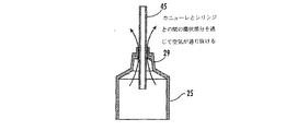
本発明の他の実施形態において、シリンジ保持ガイドは、充填ステーション内でシリンジを解放可能に保持する。シリンジ保持ガイドは、充填ステーション内でシリンジを位置決め固定するようになっているとともに、シリンジをカニューレ45と位置合わせするためのガイドとしての機能を果たすようになっている。シリンジ保持ガイドは、シリンジがオペレータによって取り付けられた後に充填ステーション内でシリンジを固定的にロックするようになっていることが好ましい。図2において、シリンジ保持ガイド50は、ガイドスリーブ52と、シリンジを把持して固定することができる把持クリップまたはクランプ54とから成るように示されている。ガイドスリーブ52は、カニューレ45がシリンジの内側壁と接触することなくシリンジ内に入るように、シリンジを充填ステーション内へと向かせる。ガイドスリーブは、カニューレがシリンジ内で中心付けられるように、シリンジを保持ガイド内へ向かせるのが好ましい。シリンジは、カニューレの少なくとも一部がシリンジ内に入るように、充填ステーション内で位置決めされなければならない。カニューレは、流体の漏れを防止する程度までシリンジ内に挿入されなければならないが、その一方で、シリンジを充填することができ且つシリンジ内から空気を逃がすことができなければならない。図7は、シリンジ25内に部分的に挿入されるカニューレ45を示している。充填プロセス中、空気は、シリンジ25の内壁とカニューレ45との間に存在する小さな通路29を通じてシリンジ内から逃げることができる。シリンジ保持ガイド50は、シリンジを解放可能に固定するためにブラケット、ストラップ、クリップ等を有していても良い。これに関して、図3および図5は、シリンジを解放可能に保持するために使用される2つの異なるタイプのシリンジ保持ガイドを有する充填ステーションを示している。一般に、保持ガイドは、シリンジを保持固定するために、シリンジの容器に対して圧力を加える。また、保持ガイド50は、シリンジを支持するためにシリンジ支持棚75を有していても良い。棚がオプションでピボット部材80を有していても良く、このピボット部材80により、棚は当該ピボット部材を中心に回動することができる。また、棚は、スライド可能に位置を変えることもできる。その結果、棚を好きなように移動させて、シリンジをシリンジ保持ガイド内に簡単に挿入することができ、あるいは、シリンジをシリンジ保持ガイドから引き出すことができる。
In other embodiments of the present invention, the syringe holding guide releasably holds the syringe within the filling station. The syringe holding guide is adapted to position and fix the syringe within the filling station and to serve as a guide for aligning the syringe with the
また、充填ステーションは、カニューレ45を覆う透明なプラスチックシールド82を含んでいても良い。そのシールドにより、オペレータは、無菌シリンジまたは投与セットを汚染させることなく充填ステーション内へのシリンジの挿入を観察することができる。
The filling station may also include a transparent
一実施形態においては、流体をリザーバからチューブ40を通じてカニューレ45へと圧送するために流体ポンプ20が使用される。この場合、カニューレ45においては、流体をシリンジ内へと導入することができる。図5に示されるように、流体ポンプ20としては、モータ22と、シャフト24と、ポンプ圧をチューブに対して加える回転可能な蠕動ヘッド26(図3参照)とを有する蠕動装置20を挙げることができる。一実施形態において、蠕動ポンプは、リニア蠕動ポンプ、回転蠕動ポンプ、または環状蠕動ポンプであっても良い。一実施形態においては、DCギアヘッドモータ22が蠕動ヘッドを駆動させることができる。更に他の実施形態において、モータは、制御ユニットまたはプロセッサに、動作可能に接続されている。プロセッサは、モータ速度を増大させ或いは減少させても良い。モータ速度を制御することにより、ポンプステーションは、所望量の流体でシリンジを正確に満たすことができる。蠕動装置は、一定の速度および可変速度で動作することができる。流体ポンプ、制御ユニット、電源、プロセッサは、通常、ハウジング内に収容されている。図2に示されるように、除去可能な筐体14がポンプ・制御ユニットを覆って取り囲んでいる。一般に、ポンプおよび制御ユニットには電力コード(図4参照、参照符号90)を用いて電力が供給される。一実施形態において、ポンプは、付加的な加圧ポンプを使用することなく、流体をリザーバからシリンジへと移動させることができる。
図3に示されるように、流体ポンプ20は締め付け機構28も有しており、この締め付け機構28を緩めることにより、チューブをポンプ内に通して蠕動ヘッド26の周囲に装着することができる。図3に示されるように、締め付け機構は、簡単に操作できるサムスクリューであっても良い。様々な異なる機構およびファスナ(締結具)を使用してチューブを固定できることは言うまでもない。他の実施形態においては、チューブ40を取り付け及び取り外すため、手動操作のためのレバー機構または特定の電気機械的な機構を使用して、蠕動ポンプ20に属するステータとローラとの間の幾何学的な隙間を開閉することができる。また、チューブと接続する蠕動ポンプ20の部分を開閉するために使用される任意の機構または装置が、チューブの取り付け及び取り外しを容易にするための幾何学的な特徴および特性を有していても良いと考えられる。そのような幾何学的な特徴および特性は、同様に、蠕動ポンプ内へのチューブの取り付け及び取り外しを容易にするため、チューブの外面に取り付けられ或いはチューブの外面上に装着される特定の中間部品と接続することができる。そうような構造は、アライメントタップのように単純であるか、あるいは、蠕動ポンプに適合するチューブを取り囲むカートリッジのように複雑であり得る。
流体リザーバは、造影剤、フラッシング剤、流体薬剤等の多種多様な異なる流体を収容していても良い。シリンジ充填ステーションは、CT注射器で使用される造影剤等の流体をシリンジに充填するのに特に役立つ。流体リザーバは、ボトル、バッグ、ポーチ、容器等の形態を成すことができる。また、リザーバは、様々なサイズをとることができる。一般的なリザーバの容積は約10から1000ccの範囲をとることができる。この場合、約50から500ccの容積が、幾分、より好ましい。例えば、CT注射器により患者に対して注入されるヨード造影剤は、通常、この範囲内のボトルおよびバッグ内に、繰り返し分配される。
In one embodiment,
As shown in FIG. 3, the
The fluid reservoir may contain a wide variety of different fluids such as contrast agents, flushing agents, fluid medicaments, and the like. The syringe filling station is particularly useful for filling syringes with fluids such as contrast agents used in CT syringes. The fluid reservoir can take the form of a bottle, bag, pouch, container or the like. In addition, the reservoir can take various sizes. Typical reservoir volumes can range from about 10 to 1000 cc. In this case, a volume of about 50 to 500 cc is somewhat more preferred. For example, iodine contrast agents that are injected into a patient by a CT syringe are typically dispensed repeatedly into bottles and bags within this range.
シリンジ充填ステーションは、この充填ステーションを制御するためにオペレータが使用できるユーザインタフェースを含んでいても良い。インタフェースを用いて入力できる一般的なコマンド機能としては、容積充填、新シリンジ、充填開始、ポーズ、停止、パージを挙げることができるが、これらに限定されない。オペレータは、シリンジ内に導入される流体の量を指定するためにインタフェースを使用することができる。本発明の一実施形態において、ユーザインタフェースは、オペレータがコマンドを入力できるタッチスクリーンの形態を成すことができる。タッチスクリーンは、充填ステーションと通信を行なうPCシステム内に組み込まれていても良く、あるいは、充填ステーションハウジング上に配置することができる。幾つかの実施形態において、シリンジ充填ステーションは、例えば注射器のユーザインタフェース上に設けることができ或いは表示可能な遠隔のインタフェースと通信し且つこのインタフェースにより制御されて動作される。シリンジ充填ステーションの制御装置は、その全体または一部が外部のユーザインタフェース上に設けることができる。これに関連して、図3に示されるように、シリンジ充填ステーションは、有線通信または無線通信のための入力/出力(I/O)端子202を含んでいても良い。図3から図6は、ハウジング12の外面上に配置されたタッチスクリーン200を示している。図8は、充填ステーションを動作させるために使用できる典型的なタッチスクリーン200を示している。タッチスクリーン200は、シリンジを充填するための幾つかの専用のコマンドを含むことができる。インタフェースは、専用のキーボード210を有していても良く、あるいは、シリンジ内に導入される流体の量を変えるための“上”矢印または“下”矢印を有していても良い。また、ユーザインタフェースは、現在のシリンジ量を示す表示220と、供給されるべき量を示す表示230とを有している。タッチスクリーン200は、“充填開始”240、“新しいシリンジの装着”250、“パージ”260等の専用のコマンド機能を有していても良い。ユーザインタフェースは、図8に示されるものに付加して或いは図8に示されるものとは異なる専用のボタンを有していても良い。他の実施形態において、ユーザインタフェースは、例えばE−Z−EM Empower CTリモート制御装置等の既存の注射器インタフェースに組み込むことができる。あるいは、シリンジ充填ステーションのデータインタフェースは、撮像装置あるいは撮像システムまたは病院内に設置された他の医療情報ITシステム等の外部の或いは遠隔のインタフェースと通信することができるとともに、当該インタフェースに対して動作可能に接続することができる。図3に示されるように、シリンジ充填ステーションは、幾つかの実施形態において、外部の制御システムまたはネットワークと通信できるI/Oポートまたはデータ相互接続部202を有することができる。データ相互接続部は、有線であっても良く、あるいは無線であっても構わない。外部インタフェースは、操作コマンドをシリンジ充填ステーションに入力するために使用できる。例えば、外部インタフェースは、シリンジ充填量を患者毎に自動的に定めるために使用できる。これにより、医療的な介護プロセスを通じ、電子的に、患者の追跡を行いやすくするのに役立てることができる。また、そのようなデータ/制御能力は、印刷装置からハードコピー情報を生成するために使用できる。特に、印刷ラベルの形態を成すそのようなハードコピーデータは、シリンジがシリンジ充填ステーションから取り外される際に識別する目的でシリンジに貼り付けることができ、その後、患者への注入にわたって取り扱うことができる。例えば、ラベル上に印刷できる有用な識別情報としては、日付、時間、充填者、患者名、患者ID番号、シリンジに充填された流体の医学名、シリンジに充填された流体の商品名、シリンジに充填された流体のロット番号、シリンジに充填された流体の量、警告、使用上の注意等及びこれらの組み合わせを挙げることができるが、これらに限定されない。幾つかの実施形態においては、前述した情報を有する簡単に利用できる印刷ラベルを提供するため、シリンジ充填ステーション内にOEMプリンタを組み込むことができる。
The syringe filling station may include a user interface that can be used by an operator to control the filling station. Common command functions that can be entered using the interface include, but are not limited to, volume filling, new syringe, filling start, pause, stop, purge. An operator can use the interface to specify the amount of fluid introduced into the syringe. In one embodiment of the present invention, the user interface may take the form of a touch screen that allows an operator to enter commands. The touch screen may be incorporated into a PC system that communicates with the filling station or may be located on the filling station housing. In some embodiments, the syringe filling station is operated and controlled by and communicates with a remote interface that can be provided, for example, on the user interface of the syringe or can be displayed. The controller of the syringe filling station can be provided in whole or in part on an external user interface. In this regard, as shown in FIG. 3, the syringe filling station may include an input / output (I / O) terminal 202 for wired or wireless communication. 3 to 6 show the
充填ステーションは、操作を行なうための制御ユニットを有していても良い。これに関連して、図4は、制御ユニット195を有するシリンジ充填ステーションを示している。制御ユニット195は、一般的に、充填ステーション中に組み込まれるマイクロプロセッサを有している。プロセッサは、ユーザインタフェース200および様々なセンサと通信することができる。制御ユニットは、充填ステーションを制御し且つユーザインタフェース、ポンプまたは様々なセンサから受けた情報およびデータを処理するためのコンピュータコードまたはプログラムを有していても良い。また、プロセッサはポンプ20に対して動作可能に接続されている。本発明の1つの他の実施形態において、プロセッサは、正確な量の流体がシリンジに供給されるようにポンプを正確に制御することができる。通常、ポンプとプロセッサは互いに通信を行なう。ポンプは、ポンプ速度やポンプ回転数等のデータをプロセッサに対して送ることができ、これにより、プロセッサは、シリンジ内に導入された流体の量を正確に計算して測定することができる。一実施形態においては、ポンプモータがエンコーダを有していても良い。この実施形態においては、エンコーダのパルスを数えることにより、シリンジに供給される量を測定することができる。使用中、プロセッサは、シリンジ内に導入された流体の量を測定する。また、プロセッサは、投与カートリッジ内に存在し得る空気を補っても良い。また、プロセッサは、付随的に、頻繁に使用される充填操作およびルーチンシステム機能を行なうために使用できるプログラム可能なコードを含むこともできる。例えば、特定の導入量が繰り返し使用される場合には、オペレータが新しいシリンジ毎に新たな充填レベルを入力する必要なく流体の設定量を供給できるように、プロセッサをプログラム可能である。
The filling station may have a control unit for performing the operation. In this connection, FIG. 4 shows a syringe filling station with a
新たな投与カートリッジがシリンジ充填ステーション内に組み込まれる場合には、チューブ内に収容された空気をパージするように、ポンプに手動または自動で指示するためにインタフェースが使用されても良い。 If a new dosing cartridge is incorporated into the syringe filling station, an interface may be used to instruct the pump manually or automatically to purge the air contained in the tube.
本発明の他の実施形態において、充填ステーションは、プロセッサと通信し且つシステムの状態を監視できるセンサを有していても良い。そのようなセンサとしては、エアー・インライン・センサまたはリザーバ・エンプティ・センサ、新しいシリンジが充填ステーション内に装着される時を検出するセンサ、投与カートリッジの存在を検出するためのセンサ、新たなリザーバが加えられた時を検出するためのセンサを挙げることができる。これらのセンサは、シリンジ充填ステーションの性能および効率を最適化するために使用できる。 In other embodiments of the present invention, the filling station may have sensors that can communicate with the processor and monitor the status of the system. Such sensors include air in-line or reservoir empty sensors, sensors that detect when a new syringe is installed in the filling station, sensors for detecting the presence of a dosing cartridge, and new reservoirs. Mention may be made of sensors for detecting when they are added. These sensors can be used to optimize the performance and efficiency of the syringe filling station.
エアー・インライン・センサは、チューブ内における空気の存在を検出することができ、あるいはリザーバ内の流体が使い果たされたことを検出することができる。センサ55は、通常、リザーバ15とポンプ20との間に配置される。図2および図3に示されるように、リザーバに隣接してセンサ55を配置することができる。チューブ40は、センサ50を貫通しても良い。エアーポケットまたは気泡がチューブ内に入ってセンサ50を通過して移動する場合、センサは、チューブ内における空気の存在を示す信号またはリザーバが使い果たされたことを示す信号をプロセッサに送ることができる。リザーバが使い果たされたことをセンサが検出すると、プロセッサは、リザーバが空になっているというメッセージを表示するようにインタフェースまたは遠隔制御装置に命令する。一実施形態では、メッセージが除かれるまでは操作が解除されない。
The air in-line sensor can detect the presence of air in the tube or can detect that the fluid in the reservoir has been exhausted. The
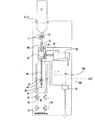
図9を参照すると、シリンジ充填ステーションの一実施形態の電気的な概略構成が示されている。図9に示されるように、プロセッサは、様々な機能を果たすとともに、多くのセンサおよび装置に対して動作可能に接続されている。また、プロセッサは、PCディスプレイまたはシリンジ充填ステーションにコマンドを入力するために使用できる他の計算CPU等の遠隔制御インタフェースと通信することもできる。 Referring to FIG. 9, a schematic electrical configuration of one embodiment of a syringe filling station is shown. As shown in FIG. 9, the processor performs various functions and is operably connected to many sensors and devices. The processor can also communicate with a remote control interface such as a PC display or other computing CPU that can be used to enter commands into the syringe filling station.
また、プロセッサは、空気をチューブ内からパージするために必要な流体の量を自動的に補うことができる。例えば、プロセッサは、新たな投与カートリッジが取り付けられた後にチューブ内の空気を補う。また、プロセッサは、新たなリザーバが取り付けられた後にシステム内に存在する空気を補うこともできる。 The processor can also automatically make up for the amount of fluid needed to purge air from within the tube. For example, the processor supplements the air in the tube after a new dosing cartridge is installed. The processor can also supplement the air present in the system after a new reservoir is installed.
また、システムは、投与カートリッジを交換する必要があることをオペレータに警告できるタイミング機構を有していても良い。オペレータが新たな投与カートリッジをシリンジ充填ステーション内に取り付けると、ハウジング12内、例えばシリンジ保持ガイドの近傍に位置された検出器は、新たなカートリッジの装着を検出することができる。センサは、新たなカートリッジが装着されたという信号を制御ユニット(プロセッサ)へ送信することができる。その後、プロセッサは、投与カートリッジを交換すべき特定の期間が経過した後にオペレータに警告するようにプログラムされた内部タイマを始動させることができる。また、シリンジ充填ステーションは、新たなシリンジがシリンジ保持ガイド内に挿入された時を検出するためのセンサを有していても良い。新たなシリンジが検出されると、プロセッサは、シリンジ量の表示をゼロにリセットするようにインタフェースに命令することができる。また、ユーザインタフェースはコマンド機能を含むこともでき、これにより、オペレータは、新たなシリンジが装着されたことを入力することができる。
The system may also have a timing mechanism that can alert the operator that the dosing cartridge needs to be replaced. When the operator installs a new dosing cartridge in the syringe filling station, a detector located in the
また、シリンジ充填ステーション10は、充填済みのシリンジをそれらが必要になるまで取り外し可能に保管するためのシリンジ保管ホルダ250を有していても良い。図4は、充填済みのシリンジ27を保管するための複数の保持クリップを有する充填ステーション10を示している。保管ホルダは、充填済みのシリンジを取り外し可能に固定する。また、シリンジ保管ホルダは、保管されたシリンジ27を患者にとって快適な温度まで加熱するための付随的なヒータ(図示せず)を有していても良い。また、充填ステーション10は、リザーバを加熱するためのヒータを付随的に有していても良い。リザーバヒータは、流体を患者にとって快適な温度まで加熱することができる。このリザーバヒータによれば、シリンジを更に加熱する必要なく、充填済みのシリンジを充填後直ぐに使用することができる。
The
本発明の一実施形態において、シリンジを流体で満たす方法は、リザーバを流体投与カートリッジに接続するステップと、流体投与カートリッジのカニューレを少なくとも部分的にシリンジ内に位置決めするステップと、蠕動ポンプを使用して流体をリザーバからシリンジへと移動させるステップとを含んでいる。他の実施形態において、シリンジ充填ステーションの動作は、投与カートリッジを充填ステーション内に装着することによって開始することができる。チューブ40は、一般的に、ポンプを貫通する。基端部とも称されるチューブの下端は、カニューレのための結合器具に接続される。チューブ40の上部は、押さえつけクランプ42を使用して所定の位置に位置決めされるとともに、エアー・インライン・センサ55を貫通する。リザーバは、スパイクに接続された後、リザーバ取付部を使用して取り外し可能に位置決めされる。その後、シリンジがシリンジ保持ガイド内に挿入され、これにより、カニューレの少なくとも一部がシリンジ内に挿入されるとともに、シリンジが充填ステーション内に解放可能に位置決めされる。その後、オペレータは、インタフェースを使用して、リザーバ内に導入する所望量の流体を定めることができる。
In one embodiment of the present invention, a method of filling a syringe with fluid uses connecting a reservoir to a fluid dispensing cartridge, positioning a cannula of the fluid dispensing cartridge at least partially within the syringe, and using a peristaltic pump. Moving the fluid from the reservoir to the syringe. In other embodiments, operation of the syringe filling station can be initiated by mounting a dosing cartridge in the filling station. The
以下の説明は、ユーザインタフェースで利用できるコマンド機能の一部を示している。新たな投与カートリッジが充填ステーション内に装着されると、制御ユニット(プロセッサ)は、カートリッジ内に収容された流体の量を自動的に補うことができる。新たなリザーバが加えられると、制御ユニットは、リザーバからエアー・インライン・センサへと与えられ得るライン中の空気を補うことができる。あるいは、投与カートリッジ内から空気を除去するためにインタフェースが“パージ”機能を含んでいても良い。動作時、ユーザは、パージボタンを押し続けることにより、低速でポンプを動作させて空気を除去することができる。システムがパージされたら、パージボタンが解放されても良い。 The following description shows some of the command functions available in the user interface. When a new dosing cartridge is installed in the filling station, the control unit (processor) can automatically make up for the amount of fluid contained in the cartridge. When a new reservoir is added, the control unit can make up for air in the line that can be fed from the reservoir to the air in-line sensor. Alternatively, the interface may include a “purge” function to remove air from within the dosing cartridge. In operation, the user can operate the pump at low speed to remove air by holding down the purge button. Once the system is purged, the purge button may be released.
前述のように、シリンジ保持ガイドは、新たなシリンジが挿入された時期を検出するセンサを有していても良い。新たなシリンジが充填ステーション内に挿入されると、ユーザインタフェースは、新たなシリンジの挿入を示す読み取りを表示するようにプログラムされていても良い。典型的なディスプレイは、例えば、“新たなシリンジの装着”を表示することができる。オペレータは、このボタンを押して、現在量の表示をリセットすることができる。あるいは、制御ユニットは、現在量を自動的にゼロにリセットするようにプログラムされていても良い。頻繁に繰り返される動作により、制御ユニットは、“充填”を変更する必要がないようにシリンジ量を記憶することができる。しかしながら、オペレータは、所望の充填量を手入力することもできる。一般に、“充填”量に表示された量が“現在量”を越えると、スタートボタンが有効にされる。スタートボタンは、“充填開始”等のコマンド機能を表示することができる。また、インタフェースは、充填量をリセットするための“クリア”等のコマンド機能を含んでいても良い。 As described above, the syringe holding guide may have a sensor that detects when a new syringe is inserted. When a new syringe is inserted into the filling station, the user interface may be programmed to display a reading indicating the insertion of a new syringe. A typical display can display, for example, “new syringe installation”. The operator can press this button to reset the current quantity display. Alternatively, the control unit may be programmed to automatically reset the current amount to zero. Frequently repeated operations allow the control unit to store the syringe volume so that it is not necessary to change the “fill”. However, the operator can also manually input a desired filling amount. Generally, the start button is activated when the amount displayed for the “fill” amount exceeds the “current amount”. The start button can display a command function such as “start filling”. Further, the interface may include a command function such as “clear” for resetting the filling amount.
一実施形態においては、“充填開始”ボタンがオペレータによって作動されると、ポンプが動作を開始する。インタフェースは、動作を停止することができる“ポーズ”コマンド機能を含むことができる。更に他の実施形態において、タッチスクリーンまたは入力ボタンは、充填ステーションによって実行される現在の動作に応じて多機能を有していても良い。例えば、タッチスクリーンが利用される場合には、ポンプ動作が開始された後、“新たなシリンジの装着”を“ポーズ”ボタンに変えることができる。シリンジ充填中、“現在量”表示は、リアルタイムで導入される流体の量を示すことができる。また、“ポーズ”ボタンが押された場合には、“充填再開”ボタンを表示するために“充填開始”ボタンをリセットすることができる。定められた量が導入されると、制御ユニットがポンプを停止し、追加の流体をシリンジ内へ導入する機会をオペレータに与えるため、“追加”ボタンを表示することができる。前述の例が、制御ユニットおよびユーザインタフェース内に組み込むことができるコマンド機能の一部の単なる典型例であることは言うまでもない。 In one embodiment, the pump begins operation when the “Start Fill” button is activated by the operator. The interface may include a “pause” command function that can stop operation. In still other embodiments, the touch screen or input button may have multiple functions depending on the current action performed by the filling station. For example, when a touch screen is used, “Install New Syringe” can be changed to a “Pause” button after the pump operation is started. During syringe filling, the “current amount” display can indicate the amount of fluid being introduced in real time. When the “pause” button is pressed, the “filling start” button can be reset to display the “filling restart” button. Once a defined amount has been introduced, an “add” button can be displayed to give the operator the opportunity to stop the pump and introduce additional fluid into the syringe. It goes without saying that the above example is merely representative of some of the command functions that can be incorporated into the control unit and user interface.
前述の説明から明らかなように、本発明は、所望量の流体をシリンジに効率的且つ正確に充填するために使用できる装置および方法を提供している。シリンジ充填ステーションは、オペレータがシリンジ内に導入される流体の量を簡単に制御できるユーザインタフェースを有していても良い。 As is apparent from the foregoing description, the present invention provides an apparatus and method that can be used to efficiently and accurately fill a syringe with a desired amount of fluid. The syringe filling station may have a user interface that allows an operator to easily control the amount of fluid introduced into the syringe.
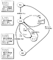
図10および図11は、シリンジ充填ステーションがシリンジを充填する際に採り得るステップを記述しているフローチャートを示す。図10は、シリンジを充填する際に生じるプロセスステップを示している。特に、図10は、プロセスの各ステップで利用できる機能を示している。図11は、シリンジ充填ステーションによって行なわれる動作を、ユーザインタフェースで利用できるコマンド機能およびポンプ状態に関連付けている。異なる別個のコマンド機能および動作も可能であり、本発明が任意の特定の組のコマンドまたは動作に限定されないことは言うまでもない。 10 and 11 show a flow chart describing the steps that can be taken when a syringe filling station fills a syringe. FIG. 10 shows the process steps that occur when filling a syringe. In particular, FIG. 10 shows the functions available at each step of the process. FIG. 11 relates the actions performed by the syringe filling station to the command functions and pump status available at the user interface. It will be appreciated that different distinct command functions and operations are possible and that the invention is not limited to any particular set of commands or operations.
1つの典型的な実施形態において、シリンジ充填ステーションは、医学画像および診断テストにおいて有用な造影剤を受けてシリンジに充填するのに良く適している。そのような診断イメージングとしては、CT、NMR/MRI、超音波診断、蛍光透視、PET等を挙げることができるが、これらに限定されない。診断テストを行なうための注射器は、一般に、約10から500ccの容積を有しており、約50から400ccの容積がより一般的である。シリンジの容積は、約100から200ccであることが好ましい。シリンジの長さは、一般的に、約2から30cmであり、シリンジの直径は一般に約0.2から5cmである。 In one exemplary embodiment, the syringe filling station is well suited for receiving and filling the syringe with contrast agents useful in medical imaging and diagnostic tests. Examples of such diagnostic imaging include, but are not limited to, CT, NMR / MRI, ultrasound diagnosis, fluoroscopy, PET, and the like. Syringes for performing diagnostic tests generally have a volume of about 10 to 500 cc, with a volume of about 50 to 400 cc being more common. The volume of the syringe is preferably about 100 to 200 cc. The length of the syringe is typically about 2 to 30 cm and the diameter of the syringe is typically about 0.2 to 5 cm.
ここに記載された本発明の変形例および他の実施形態は、これらの発明が属する技術分野における当業者であって前述した説明および添付図面に示された教示内容の利益を得る当業者であれば想起し得る。したがって、本発明が開示された特定の実施形態に限定されないことは言うまでもなく、また、変形例および他の実施形態が添付の請求の範囲内に含まれることは言うまでもない。ここでは特定の用語が使用されているが、これらの用語は、単に包括的且つ記述的な意味で使用されており、限定を目的としているものではない。また、本発明は、ここに記載された要素を適切に備えていても良く、当該要素から成っていても良く、基本的に当該要素から成っていても良い。また、ここに記載された要素は、ここに具体的に開示され或いは開示されていない任意の要素無くして実行されても良い。 Variations and other embodiments of the present invention described herein are intended to enable those skilled in the art to which these inventions pertain and which benefit from the teachings presented in the foregoing description and accompanying drawings. It can be recalled. Thus, it should be understood that the invention is not limited to the specific embodiments disclosed, and that variations and other embodiments are included within the scope of the appended claims. Although specific terms are used herein, these terms are used in a comprehensive and descriptive sense only and are not intended to be limiting. In addition, the present invention may appropriately include the elements described herein, and may include the elements, or may basically include the elements. Also, elements described herein may be practiced without any elements specifically disclosed or not disclosed herein.
説明の全体にわたって、特定の部品を有する、含む、または、備えるように実施形態が記載されている場合、あるいは、特定のステップを有する、含む、または、備えるように方法が記載されている場合には、本発明の実施形態が、記載された部品から基本的に成り或いは当該部品から成ることも考慮されており、また、本発明の方法が、記載された方法ステップから基本的に成り或いは当該方法ステップから成ることも考慮されている。また、本発明が動作可能な状態を保つ限り、ステップの順番または特定の動作を行なうための順番は、変わっても良く、特定の不変の順序にしたがって行なわれる必要がないことは言うまでもない。また、2つ以上のステップまたは動作が同時に行なわれても良い。 Throughout the description, when embodiments are described as having, including, or comprising specific parts, or when methods are described as having, including, or including certain steps. It is also contemplated that embodiments of the present invention consist essentially of or consist of the described parts, and that the method of the present invention consists essentially of the described method steps or It is also considered to consist of method steps. Further, as long as the present invention remains operable, it goes without saying that the order of steps or the order for performing a specific operation may be changed and need not be performed according to a specific invariant order. Two or more steps or operations may be performed simultaneously.
Claims (56)
b)シリンジを解放可能に固定するためのシリンジ保持ガイドと、
c)リザーバとシリンジとの間に流体通路を形成する消耗投与カートリッジであって、リザーバ内に挿入するための突出部材と、先端部が前記突出部材に取り付けられる可撓性チューブと、前記可撓性チューブの基端に対して取り付けられ且つ少なくとも一部がシリンジ内に挿入されるようになっているカニューレとを備えている消耗投与カートリッジと、
d)前記流体をリザーバから前記投与カートリッジを通じてシリンジ内へと圧送するためのポンプと、
を備える、流体をシリンジ内に供給するための装置。 a) a reservoir mounting for removably receiving a reservoir having fluid;
b) a syringe holding guide for releasably fixing the syringe;
c) A consumable administration cartridge that forms a fluid passage between a reservoir and a syringe, a protruding member for insertion into the reservoir, a flexible tube having a tip attached to the protruding member, and the flexible A consumable dosing cartridge comprising a cannula attached to a proximal end of the sex tube and adapted to be at least partially inserted into the syringe;
d) a pump for pumping the fluid from the reservoir through the dosing cartridge and into the syringe;
A device for supplying fluid into a syringe.
前記リザーバ内に挿入される突出部材と、先端部が前記突出部材に対して取り付けられる可撓性チューブと、前記可撓性チューブの基端に対して取り付けられるカニューレとを有する流体供給システムと、
ほぼ細長い本体を有するシリンジであって、その吐出部位の近傍に通路が配置され、この通路内へと前記カニューレが延びることにより流体をリザーバからシリンジ内へと供給できるシリンジと、
流体を前記リザーバから前記シリンジへと圧送するためのポンプと、
前記ポンプに対して動作可能に接続され、これにより、特定の量の流体がシリンジへと送り込まれるように前記ポンプを制御できる制御ユニットと、
を備えるシリンジ充填ステーション。 A reservoir having a fluid medium;
A fluid supply system having a protruding member inserted into the reservoir, a flexible tube having a distal end portion attached to the protruding member, and a cannula attached to a proximal end of the flexible tube;
A syringe having a generally elongate body, wherein a passageway is disposed near the discharge site, and the cannula extends into the passageway to allow fluid to be supplied from the reservoir into the syringe;
A pump for pumping fluid from the reservoir to the syringe;
A control unit that is operably connected to the pump, thereby controlling the pump such that a specific amount of fluid is pumped into the syringe;
A syringe filling station comprising:
b)前記流体投与カートリッジのカニューレを少なくとも部分的に前記シリンジ内に位置決めするステップと、
c)蠕動ポンプを使用して流体を前記リザーバから前記シリンジへと移動させるステップと、
を含む、シリンジに流体を充填する方法。 a) connecting the reservoir to the fluid dispensing cartridge;
b) positioning the cannula of the fluid dispensing cartridge at least partially within the syringe;
c) moving fluid from the reservoir to the syringe using a peristaltic pump;
A method of filling a syringe with fluid.
b)突出部材と、カニューレと、可撓性チューブとを有する流体供給システムを用意するステップと、
c)前記流体供給システムを前記充填ステーション内に取り付けて、前記リザーバ取付部から前記シリンジ保持ガイドへと向かう流体通路を形成するステップと、
d)流体リザーバを前記リザーバ取付部に対して接続するステップと、
e)前記カニューレの少なくとも一部がシリンジ内に部分的に挿入されるように、シリンジを前記保持ガイド内に挿入するステップと、
f)流体を前記リザーバから前記シリンジへと圧送するステップと、
を含む、シリンジに流体を充填する方法。 a) providing a filling station having a reservoir mount for removably receiving the reservoir, a fluid pump, and a syringe holding guide;
b) providing a fluid supply system having a protruding member, a cannula, and a flexible tube;
c) mounting the fluid supply system in the filling station to form a fluid path from the reservoir mount to the syringe holding guide;
d) connecting a fluid reservoir to the reservoir mount;
e) inserting a syringe into the holding guide such that at least a portion of the cannula is partially inserted into the syringe;
f) pumping fluid from the reservoir to the syringe;
A method of filling a syringe with fluid.
Applications Claiming Priority (2)
| Application Number | Priority Date | Filing Date | Title |
|---|---|---|---|
| US47657803P | 2003-06-06 | 2003-06-06 | |
| PCT/US2004/017802 WO2004108533A1 (en) | 2003-06-06 | 2004-06-04 | Peristaltic syringe filling station |
Publications (1)
| Publication Number | Publication Date |
|---|---|
| JP2006527140A true JP2006527140A (en) | 2006-11-30 |
Family
ID=33511800
Family Applications (1)
| Application Number | Title | Priority Date | Filing Date |
|---|---|---|---|
| JP2006515209A Pending JP2006527140A (en) | 2003-06-06 | 2004-06-04 | Apparatus for supplying fluid into a syringe, syringe filling station and method for filling a syringe with fluid |
Country Status (5)
| Country | Link |
|---|---|
| EP (1) | EP1636092B1 (en) |
| JP (1) | JP2006527140A (en) |
| KR (1) | KR100744734B1 (en) |
| AT (1) | ATE519677T1 (en) |
| WO (1) | WO2004108533A1 (en) |
Families Citing this family (6)
| Publication number | Priority date | Publication date | Assignee | Title |
|---|---|---|---|---|
| US7163031B2 (en) * | 2004-06-15 | 2007-01-16 | Mallinckrodt Inc. | Automated dispensing system and associated method of use |
| US20060064070A1 (en) * | 2004-09-07 | 2006-03-23 | Jeffrey Martin | Methods and devices for sterile field transfer |
| US7571747B2 (en) | 2006-01-09 | 2009-08-11 | Spitz Gregory A | Syringe filling apparatus |
| ITBO20060619A1 (en) * | 2006-08-30 | 2008-02-29 | Tema Sinergie S R L | AUTOMATIC MACHINE FOR FRACTIONING A RADIOACTIVE LIQUID. |
| WO2008036555A2 (en) | 2006-09-18 | 2008-03-27 | Alcon, Inc. | Surgical console |
| US20110315269A1 (en) * | 2010-06-25 | 2011-12-29 | Bioject, Inc. | High workload injection system |
Citations (5)
| Publication number | Priority date | Publication date | Assignee | Title |
|---|---|---|---|---|
| JPH09103484A (en) * | 1995-10-13 | 1997-04-22 | Suzuki Seisakusho:Kk | Syringe filling device and filling method |
| JPH10509358A (en) * | 1994-11-07 | 1998-09-14 | ポール エス タイアースタイン | Radiographic dye supply apparatus and supply method |
| JPH1135001A (en) * | 1997-07-16 | 1999-02-09 | Suugan Kk | Fluid filler |
| JP2000506425A (en) * | 1996-12-09 | 2000-05-30 | バクスター・インターナショナル・インコーポレイテッド | Nutrient fluid dispensing assembly |
| JP2002326607A (en) * | 2001-04-26 | 2002-11-12 | Matsushita Electric Works Ltd | Filling device and filling method of liquid-form resin to syringe |
Family Cites Families (6)
| Publication number | Priority date | Publication date | Assignee | Title |
|---|---|---|---|---|
| US4998570A (en) * | 1988-06-27 | 1991-03-12 | Pavel Jordan & Associates | Filling device with sound indicator for filling injection syringe |
| US5647409A (en) * | 1995-04-04 | 1997-07-15 | Allergan | On-site syringe filling apparatus for viscoelastic materials, and corresponding method for on-site syringe filling |
| US5782805A (en) * | 1996-04-10 | 1998-07-21 | Meinzer; Randolph | Medical infusion pump |
| US5911252A (en) * | 1997-04-29 | 1999-06-15 | Cassel; Douglas | Automated syringe filling system for radiographic contrast agents and other injectable substances |
| WO2000068137A1 (en) * | 1999-05-08 | 2000-11-16 | Neas Edwin D | Apparatus for automatic preparation of a mixture and method |
| US20020107501A1 (en) * | 2001-02-02 | 2002-08-08 | Smith James E. | Weight dependent, automatic filling dosage system and method of using same |
-
2004
- 2004-06-04 KR KR1020057023427A patent/KR100744734B1/en not_active IP Right Cessation
- 2004-06-04 WO PCT/US2004/017802 patent/WO2004108533A1/en active Application Filing
- 2004-06-04 EP EP04754413A patent/EP1636092B1/en active Active
- 2004-06-04 AT AT04754413T patent/ATE519677T1/en not_active IP Right Cessation
- 2004-06-04 JP JP2006515209A patent/JP2006527140A/en active Pending
Patent Citations (5)
| Publication number | Priority date | Publication date | Assignee | Title |
|---|---|---|---|---|
| JPH10509358A (en) * | 1994-11-07 | 1998-09-14 | ポール エス タイアースタイン | Radiographic dye supply apparatus and supply method |
| JPH09103484A (en) * | 1995-10-13 | 1997-04-22 | Suzuki Seisakusho:Kk | Syringe filling device and filling method |
| JP2000506425A (en) * | 1996-12-09 | 2000-05-30 | バクスター・インターナショナル・インコーポレイテッド | Nutrient fluid dispensing assembly |
| JPH1135001A (en) * | 1997-07-16 | 1999-02-09 | Suugan Kk | Fluid filler |
| JP2002326607A (en) * | 2001-04-26 | 2002-11-12 | Matsushita Electric Works Ltd | Filling device and filling method of liquid-form resin to syringe |
Also Published As
| Publication number | Publication date |
|---|---|
| EP1636092B1 (en) | 2011-08-10 |
| EP1636092A4 (en) | 2010-01-20 |
| KR20060009382A (en) | 2006-01-31 |
| EP1636092A1 (en) | 2006-03-22 |
| WO2004108533A1 (en) | 2004-12-16 |
| ATE519677T1 (en) | 2011-08-15 |
| KR100744734B1 (en) | 2007-08-01 |
Similar Documents
| Publication | Publication Date | Title |
|---|---|---|
| US8220504B2 (en) | Peristaltic syringe filling station | |
| EP2416824B1 (en) | Power injector with vacuum-assisted syringe filling | |
| US8628514B2 (en) | Multi-dose medical fluid injection system having patient-specific tubing set with use indicator | |
| US8262610B2 (en) | Catheter fluid control system | |
| US8463362B2 (en) | Multi-dose injection system | |
| US20070197963A1 (en) | Medical fluid injection and inflation system | |
| CN116370745A (en) | Medical fluid injection device, medical fluid injection system, syringe, and switch unit | |
| EP1769811A1 (en) | Medicinal liquid injection system | |
| CN110234375B (en) | Acoustic frequency identification of patient lines | |
| WO2012126745A2 (en) | Methods and devices for operating an infusion system | |
| CN110944695B (en) | Handling device and multiple injection device | |
| US8839828B2 (en) | Filling device having cooling and system for administering a liquid medication | |
| JP2009532112A (en) | Fluid delivery system with bulk container and pump assembly | |
| JP2008136786A (en) | Radioactive drug administration device | |
| EP1839698A1 (en) | Tube connection apparatus | |
| JP2006527140A (en) | Apparatus for supplying fluid into a syringe, syringe filling station and method for filling a syringe with fluid | |
| KR20110074906A (en) | Mating mechanism for a pressurizing unit and corresponding sleeve in a medical fluid injection device | |
| WO2008004669A1 (en) | Chemical liquid loading and injection system | |
| EP3843825A1 (en) | Utilizing pressure measurements to detect reuse of patient lines |
Legal Events
| Date | Code | Title | Description |
|---|---|---|---|
| A131 | Notification of reasons for refusal |
Free format text: JAPANESE INTERMEDIATE CODE: A131 Effective date: 20081028 |
|
| A601 | Written request for extension of time |
Free format text: JAPANESE INTERMEDIATE CODE: A601 Effective date: 20090113 |
|
| A602 | Written permission of extension of time |
Free format text: JAPANESE INTERMEDIATE CODE: A602 Effective date: 20090120 |
|
| A711 | Notification of change in applicant |
Free format text: JAPANESE INTERMEDIATE CODE: A711 Effective date: 20090205 |
|
| A02 | Decision of refusal |
Free format text: JAPANESE INTERMEDIATE CODE: A02 Effective date: 20090707 |