JP2006520002A - Builder's measurement and marking tools - Google Patents
Builder's measurement and marking tools Download PDFInfo
- Publication number
- JP2006520002A JP2006520002A JP2006509210A JP2006509210A JP2006520002A JP 2006520002 A JP2006520002 A JP 2006520002A JP 2006509210 A JP2006509210 A JP 2006509210A JP 2006509210 A JP2006509210 A JP 2006509210A JP 2006520002 A JP2006520002 A JP 2006520002A
- Authority
- JP
- Japan
- Prior art keywords
- scoring
- builder
- tool
- measurement
- ruled
- Prior art date
- Legal status (The legal status is an assumption and is not a legal conclusion. Google has not performed a legal analysis and makes no representation as to the accuracy of the status listed.)
- Granted
Links
- 238000005259 measurement Methods 0.000 title claims description 42
- 238000000034 method Methods 0.000 claims description 3
- 238000007373 indentation Methods 0.000 claims description 2
- 238000012986 modification Methods 0.000 description 2
- 230000004048 modification Effects 0.000 description 2
- 241000238876 Acari Species 0.000 description 1
- 235000002492 Rungia klossii Nutrition 0.000 description 1
- 244000117054 Rungia klossii Species 0.000 description 1
- 230000002411 adverse Effects 0.000 description 1
- 238000010276 construction Methods 0.000 description 1
- 230000000694 effects Effects 0.000 description 1
- 230000002093 peripheral effect Effects 0.000 description 1
- 230000001012 protector Effects 0.000 description 1
- 238000007493 shaping process Methods 0.000 description 1
Images


Classifications
-
- E—FIXED CONSTRUCTIONS
- E04—BUILDING
- E04D—ROOF COVERINGS; SKY-LIGHTS; GUTTERS; ROOF-WORKING TOOLS
- E04D15/00—Apparatus or tools for roof working
- E04D15/02—Apparatus or tools for roof working for roof coverings comprising tiles, shingles, or like roofing elements
- E04D15/025—Templates, gauges or spacers for installing roof tiles or roof laths
-
- B—PERFORMING OPERATIONS; TRANSPORTING
- B43—WRITING OR DRAWING IMPLEMENTS; BUREAU ACCESSORIES
- B43L—ARTICLES FOR WRITING OR DRAWING UPON; WRITING OR DRAWING AIDS; ACCESSORIES FOR WRITING OR DRAWING
- B43L7/00—Straightedges
- B43L7/027—Plural non-adjustable straightedges fixed at right angles
- B43L7/0275—Triangles
-
- G—PHYSICS
- G01—MEASURING; TESTING
- G01B—MEASURING LENGTH, THICKNESS OR SIMILAR LINEAR DIMENSIONS; MEASURING ANGLES; MEASURING AREAS; MEASURING IRREGULARITIES OF SURFACES OR CONTOURS
- G01B3/00—Measuring instruments characterised by the use of mechanical techniques
- G01B3/02—Rulers with scales or marks for direct reading
- G01B3/04—Rulers with scales or marks for direct reading rigid
-
- G—PHYSICS
- G01—MEASURING; TESTING
- G01B—MEASURING LENGTH, THICKNESS OR SIMILAR LINEAR DIMENSIONS; MEASURING ANGLES; MEASURING AREAS; MEASURING IRREGULARITIES OF SURFACES OR CONTOURS
- G01B3/00—Measuring instruments characterised by the use of mechanical techniques
- G01B3/56—Gauges for measuring angles or tapers, e.g. conical calipers
- G01B3/566—Squares
Abstract
Description
本出願は、35合衆国法典ξ119(e)の利益を主張し、2003年3月7日出願の米国特許仮出願第60/453,099号を参照し本発明の一部とするものである。 This application claims the benefit of 35 US Code ξ119 (e), and is incorporated by reference in US Provisional Application No. 60 / 453,099, filed Mar. 7, 2003.
本発明は、屋根ふき又は構造物の骨組みに使用するための屋根ふき用直角定規の様な測定及び罫引き用工具の分野に関する。
様々な三角形の屋根ふき用直角定規が基本的な屋根の建築に使用されることは既知である。これらを使えば、大工は、普通垂木や、隅木及び谷木を含め、屋根の骨組みを作るための様々な種類の垂木を測定し切断することができる。例えば、既知の屋根ふき用直角定規を使えば、ユーザーは、ライズ測定用の物差しのような1つの測定物差しだけを使って、隅木及び谷木の垂直切断印を付けることができる。
The present invention relates to the field of measuring and scoring tools such as a roofing right angle ruler for use in roofing or structural frameworks.
It is known that various triangular roofing right angle rulers are used in basic roof construction. With these, carpenters can measure and cut various types of rafters for building roof frames, including ordinary rafters, corners and valleys. For example, using a known roofing right angle ruler, a user can use only one measuring ruler, such as a rise measuring ruler, to mark vertical cuts in corners and valleys.
更に、既知の屋根ふき用直角定規を使えば、大工は、直角定規の特定の造形部を鉛直線と整列させることによって垂木に水平、即ち、シートカットの欠き込みを罫引くことができる。この造形部の唯一の目的は、シートカットの欠き込みを罫引くことである。異なる機能を実施するための別の構造を直角定規に加えるとすれば、シートカット欠き込み造形部の位置と形状を変更する必要が生じるであろう。これは、大工が、造形部を鉛直線と正確に整列させるのをより困難にするので、シートカット欠き込み造形部の効果に悪影響を与える。 In addition, with the known roofing right angle ruler, the carpenter can mark the rafters horizontally, i.e., the notch of the sheet cut, by aligning a particular shaped part of the right angle ruler with the vertical line. The only purpose of this shaping part is to draw a notch in the sheet cut. If another structure for performing different functions is added to the right angle ruler, the position and shape of the sheet cut notched features will need to be changed. This makes it more difficult for the carpenter to accurately align the shaped part with the vertical line, thus adversely affecting the effect of the sheet cut notched shaped part.
従って、屋根の骨組みを作るための垂木に様々な種類の切断部を罫引くための簡単で効果的な手段を有する屋根ふき用直角定規が必要とされてきた。。 Accordingly, there has been a need for a roofing right angle ruler that has a simple and effective means for scoring various types of cuts in a rafter for building a roof framework. .
本発明のひとつの態様では、建築者の測定及び罫引き工具を提供している。この工具は、第1側辺と、第1側辺に対し垂直に延びる第2側辺と、第1及び第2側辺と交差して直角三角形の斜辺を形成する第3側辺とを含む直角三角形を有する平板状の部材を備えている。本工具は、また、第3側辺から内側に間隔を空けて配置され、第3側辺に平行した少なくとも1つの直線状の辺によって境界が定められている細長開口部を備えている。本工具は、更に、細長開口部の少なくとも1つの直線状の辺に沿って形成されている第1隅木谷木罫引き目盛を備えている。更に、本工具は、細長開口部の少なくとも1つの直線状の辺に平行な第1内側側辺と、第1内側側辺に沿って形成されている第2隅木谷木罫引き目盛とを有する開口部を備えている。 In one aspect of the invention, a builder's measurement and scoring tool is provided. The tool includes a first side, a second side that extends perpendicular to the first side, and a third side that intersects the first and second sides to form a hypotenuse of a right triangle. A flat plate-like member having a right triangle is provided. The tool also includes an elongated opening that is spaced inward from the third side and is bounded by at least one linear side that is parallel to the third side. The tool further includes a first corner, valley and line ruled scale formed along at least one straight side of the elongated opening. The tool further includes a first inner side parallel to at least one linear side of the elongated opening, and a second corner tree / valley ruled scale formed along the first inner side. It has an opening.
本発明の別の態様でも、建築者の測定及び罫引き工具を提供している。この工具は、第1側辺と、第1側辺に対し垂直に延びる第2側辺と、第1及び第2側辺と交差して直角三角形の斜辺を形成する第3側辺とを含む直角三角形を有する平板状の部材を備えている。本工具は、更に、第3側辺から内側に間隔を空けて配置され、第3側辺に平行な相対する直線状の辺によって境界が定められている細長開口部を備えている。本工具は、更に、第2側辺から内側に間隔を空けて配置され、第2側辺に平行な少なくとも1つの罫書き辺を有する罫書き棒状部を備えている。罫書き辺は、第1側辺から所定の距離に少なくとも1つの欠刻を含んでいる。更に、本工具は、互いに直角に交差する第1内側側辺及び第2内側側辺と、直角三角形開口部の斜辺となる第3内側側辺とを有する直角三角形形状の開口部を備えている。第3内側側辺は、細長開口部の相対する直線状の辺に平行である。 Another aspect of the invention provides a builder's measurement and scoring tool. The tool includes a first side, a second side that extends perpendicular to the first side, and a third side that intersects the first and second sides to form a hypotenuse of a right triangle. A flat plate-like member having a right triangle is provided. The tool further includes an elongated opening that is spaced inward from the third side and is bounded by opposing linear sides parallel to the third side. The tool further includes a scribing bar-like portion that is disposed at an interval from the second side to the inside and has at least one scoring side parallel to the second side. The ruled side includes at least one notch at a predetermined distance from the first side. The tool further includes a right triangular opening having a first inner side and a second inner side that intersect at right angles with each other, and a third inner side that is the hypotenuse of the right triangular opening. . The third inner side is parallel to the opposing straight sides of the elongated opening.
本発明の更に別の態様でも、建築者の測定及び罫引き工具を提供している。この工具は、第1側辺と、第1側辺に対し垂直に延びる第2側辺と、第1及び第2側辺と交差して直角三角形の斜辺を形成する第3側辺とを含む直角三角形を有する平板状の部材を備えている。第1側辺と第2側辺の交点が枢軸点である。本工具は、更に、第2側辺が工作物上をわたって配置されるときに、工作物に当接させる、第1側辺に沿った当接手段を備えている。本工具は、更に、第1側辺からの距離を印すための、材木の標準的な幅に相当する所定の距離を含む第2側辺に沿って形成されている距離罫書き目盛を備えている。本工具は、更に、角を罫引き、普通垂木の鉛直線に対する度数測定値を罫引くための、第3側辺に沿って形成されている角度罫書き目盛を備えている。本工具は、更に、第2側辺から内側に間隔を空けて配置されている罫書き棒状部を備えている。罫書き棒状部は、第2側辺に平行な少なくとも1つの罫書き辺を有している。罫書き辺は、材木の標準的な幅に相当する第1側辺からの所定距離に、少なくとも1つの欠刻を含んでいる。本工具は、更に、第3側辺から内側に間隔を空けて配置され、第3側辺に平行な相対する直線状の辺によって境界が定められている細長開口部を備えている。本工具は、更に、普通垂木の鉛直線に対してライズ値を罫引くための、細長開口部の第1の直線状の辺に沿って形成されている普通垂木罫引き目盛を備えている。本工具は、更に、隅木及び谷木の鉛直線に対してライズ値及び度数測定値を罫引くための、細長開口部の第2の直線状の辺に沿って形成されている第1隅木谷木罫引き目盛を備えている。本工具は、更に、互いに直角に交差する第1内側側辺及び第2内側側辺と、直角三角形開口部の斜辺となる第3内側側辺とを有する直角三角形形状の開口部を備えている。第3内側側辺は、細長開口部の相対した直線状の辺に平行である。本工具は、更に、ライズ値及び度数測定値の内の、第1隅木谷木罫引き目盛を使って罫引かれていないどちらか一方を罫引くための、第3内側側辺に沿って形成されている第2隅木谷木罫引き目盛を備えている。本工具は、更に、第1内側側辺に沿って形成され、第2側辺からの距離を表示している直線状罫引き目盛を備えている。 Yet another aspect of the present invention provides a builder's measurement and scoring tool. The tool includes a first side, a second side that extends perpendicular to the first side, and a third side that intersects the first and second sides to form a hypotenuse of a right triangle. A flat plate-like member having a right triangle is provided. The intersection of the first side and the second side is the pivot point. The tool further includes contact means along the first side for contacting the workpiece when the second side is disposed over the workpiece. The tool further includes a distance scoring scale formed along the second side including a predetermined distance corresponding to the standard width of the timber for marking the distance from the first side. ing. The tool further comprises an angle scoring scale formed along the third side for scoring corners and scoring power measurements for normal rafter vertical lines. The tool further includes a scribing bar-like portion arranged at an interval from the second side to the inside. The ruled bar portion has at least one ruled side parallel to the second side. The ruled side includes at least one notch at a predetermined distance from the first side corresponding to the standard width of the timber. The tool further includes an elongated opening that is spaced inward from the third side and is bounded by opposing linear sides parallel to the third side. The tool further includes a normal rafter ruler scale formed along the first straight side of the elongated opening for marking the rise value with respect to the vertical line of the normal rafter. The tool further includes a first corner valley formed along the second straight side of the elongated opening for ruled rise values and frequency measurement values with respect to the vertical lines of the corner trees and valley trees. It has a wooden ruled scale. The tool further includes a right triangular opening having a first inner side and a second inner side intersecting at right angles to each other and a third inner side serving as a hypotenuse of the right triangular opening. . The third inner side is parallel to the opposed linear sides of the elongated opening. The tool is further formed along the third inner side for scoring one of the rise value and the frequency measurement value that is not crooked using the first sumiki-tani ruled graduation scale. The second Sumiki Taniki ruled scale is provided. The tool further includes a linear ruled scale formed along the first inner side and displaying the distance from the second side.
本発明の更に別の態様では、建築者の測定及び罫引き工具を使ってシートカット欠き込みを工作物に罫引く方法を提供している。この工具は、直角三角形を有する平板状の部材であって、第1側辺及び第1側辺に対して垂直に延びる第2側辺と、第1側辺に沿う当接手段と、第1側辺からの距離を印すための、材木の標準的な幅に相当する所定の距離を含み第2側辺に沿って形成されている距離罫引き目盛と、第2側辺から内側に間隔を空けて配置され、第1側辺から所定の距離に配置されている少なくとも1つの欠刻を含む、第2側辺に平行な少なくとも1つの罫書き辺を有する罫書き棒状部と、を有する。本方法は、工作物に鉛直線を引く段階と;建築者の測定及び罫引き工具を、工作物上に、当接手段を工作物の側辺に沿わせて配置する段階と;建築者の測定及び罫引き工具を、工作物の側辺に沿って、所定の距離を示す距離罫引き目盛が鉛直線と重なるまで滑動させる段階と;建築者の測定及び罫引き工具を、第1側辺と第2側辺の交点で画定される枢軸点を中心として、鉛直線が、所定の距離を示す距離罫引き目盛と、第1側辺から所定の距離に配置されている罫書き棒の欠刻の両方と交差するまで、回転させる段階と;シートカット欠き込み切断線を、工具の第2の直線状の辺に沿って、鉛直線から工作物の側辺まで罫引く段階を含んでいる。 In yet another aspect of the present invention, a method for scoring a sheet cut notch into a workpiece using a builder's measurement and scoring tool is provided. The tool is a flat plate-like member having a right triangle, the first side and the second side extending perpendicularly to the first side, contact means along the first side, A distance ruled scale formed along the second side including a predetermined distance corresponding to the standard width of the timber for marking the distance from the side, and an interval from the second side to the inside A scribing bar-shaped portion having at least one scoring side parallel to the second side and including at least one notch disposed at a predetermined distance from the first side. . The method includes drawing a vertical line on the work piece; placing the builder's measurement and scoring tool on the work piece with the abutment means along the side of the work piece; Sliding the measuring and scoring tool along the side of the workpiece until the distance scoring scale indicating the predetermined distance overlaps the vertical line; and the builder's measuring and scoring tool on the first side Centered on the pivot point defined by the intersection of the second side and the vertical line, the vertical line is a distance ruled scale indicating a predetermined distance, and a ruler bar arranged at a predetermined distance from the first side is missing. Rotating the sheet until it intersects both of the ticks; scoring the sheet cut notch cutting line from the vertical line to the side of the workpiece along the second straight side of the tool .
本発明による建築者の測定及び罫引き工具2は、図1と図2に示される。代表的な工具2には、メートル法測定単位を画定する様々な目盛が設けられている。しかしながら、容易に理解頂けるように、メートル法の尺度が本発明を実施するための唯一の測定尺度ではなく、工具2には、英国の測定単位インチの様な他の測定単位を画定する目盛を使用することもできる。
A builder's measurement and
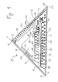
図1に示すように、建築者の測定及び罫引き工具2は、時には屋根ふき用直角定規とも呼ばれる直角三角形の周辺形状を有する平板状部材4を備えており、第1側辺6と第2側辺10が、それぞれの第1端部8と第1端部12で互いに直角に交わり、枢軸点9を形成している。平板状部材4は、更に、直角三角形工具2の斜辺を形成する、対向する端部16及び20を有する第3側辺14を有している。第3側辺14は、一方の端部16で、第1側辺6と第1側辺の反対側の端部18で交差しており、その反対側の端部20で、第2側辺10と第2側辺の反対側の端部22で交差している。
As shown in FIG. 1, the builder's measuring and
測定及び罫引き工具2は、図2に示すように、一方の方向に面する第1平面24と、反対の方向に面する第2平面26を有しており、両平面は平行で、例えば、約16分の3インチから4分の1インチの距離だけ離れた面である。第1の平滑で直線状の壁面28は、そのような両平面の間を第2側辺10に沿って延び罫引き辺を形成し、この罫引き辺に沿って鉛筆を滑らせ直線状の平滑な線を引くことができるようになっている。第2の平滑で直線状の壁面30は、両平面の間を第3側辺14に沿って延び、これも工具2のこの側辺に沿って平滑な罫引き辺を形成している。
As shown in FIG. 2, the measuring and
図2に示されるように、T字型の棒32は、第1側辺6に沿って設けられており、第1平面24から垂直に、これに向かって内向きに向いた、約4分の1インチの短い距離だけ外方向に突出する平面を有する第1棚状突起34と、第2の反対向きの平面26から垂直に、これに向かって内向きに向いた、約四分の一インチの短い距離だけ外方向に突出する平面を有する第2棚状突起36とを有している。T字棒32は、外方向に工具2から遠ざかる方向に向いた反対側平面38を有している。第1及び第2第2棚状突起34と36のこれらの寸法は、実例であって、限定を加えるものではない。当業者には容易に分かることであるが、T字棒32は、別の寸法でもよく、第1側辺6が当たるストッパになるのであれば、棚状突起34及び36の代わりの当接手段として、他の突出部、リップ又はフランジを用いてもよい。
As shown in FIG. 2, the T-
図1に戻るが、第2側辺10は、第1側辺6の端部8に隣接する端部12を起点とする距離罫引き目盛40をその側辺に沿って有している。本実施形態では、距離罫引き目盛40は、第1平面24と第2平面26の両方に、0.5センチメートル刻みで形成されており、数字は、第1側辺6の端部8から最初の1センチメートル離れていることを示す数字1で始まり、それぞれ順次対応するセンチメートルを示している。
Returning to FIG. 1, the
斜辺即ち第3側辺14には、角度罫引き目盛42が、第1平面24と第2平面26の両方に、その側辺に沿って形成されている。本実施形態では、角度罫引き目盛42は、第1側辺6の端部18に隣接する第3側辺の端部16から始まる度数の尺度を画定している。
On the oblique side, that is, the
本発明による測定及び罫引き工具2は、更に、第2側辺10に平行に配置され、そこから内側に、例えば約8分の5インチの距離だけ間隔を空けて配置される罫書き棒状部44を含んでいる。罫書き棒状部44は、平行な罫書き辺44a及び44bによって境界が定められており、各辺は、第2側辺10に沿って形成されている距離罫引き目盛40に対応する欠刻46を有している。本実施形態では、連続する欠刻46は、罫書き辺44aと44bの間で互い違いになっており、連続する欠刻46の間の0.5センチメートルの増加を定めている。この形状構成は、また、罫書き辺44aと44bに形成されている隣接する欠刻46の間が1センチメートルとなっている。罫書き棒状部44は、第1側辺6の端部8から、10.5センチメートルの距離、即ち製材又は材木の標準的なメートル法の幅、に形成されている罫引き目盛40aに対応する欠刻46aを含んでいる。
The measuring and
本発明による測定及び罫引き工具2は、平行する直線状の辺52と54によって境界を定められている細長開口部50を含んでいる。この開口部は、直角定規2の斜辺即ち第3側辺14に平行であり、そこから内側に、例えば約1と4分の1インチの距離だけ間隔を空けて配置されている。第1隅木谷木罫引き目盛58は、第1平面24と第2平面26の両方に、細長開口部50の直線状の辺52に沿って形成されている。本実施形態では、例えば、第1隅木谷木罫引き目盛58は、隅木及び谷木の鉛直線を測定するため度数の尺度を規定している。
The measuring and
普通垂木罫引き目盛56は、普通垂木に対する鉛直線を測定するために、第1平面24と第2平面26の両方に、細長開口部50の直線状の辺54に沿って形成されている。本実施形態では、例えば、普通垂木罫引き目盛56は、垂木の水平距離10センチメートル毎に上昇するセンチメートル高さに相当するライズ値の尺度を規定している。
The normal rafter ruled
測定及び罫引き工具2は、更に、互いに直角に交わる第1内側側辺62及び第2内側側辺64と、斜辺となる第3内側側辺66とを有する直角三角形形状のほぼ三角形の開口部60を含んでいる。斜辺即ち第3内側側辺66は、細長開口部50の直線状の辺52及び54に平行であり、直線状の辺54から、例えば約4分の3インチの距離だけ間隔を空けて配置されている。三角形開口部60の第1内側側辺62は、工具2の第1内側側辺6に平行であり、その内側に、例えば約8分の5インチの距離だけ間隔を空けて配置されている。三角形開口部60の第2内側側辺64は、工具2の第2側辺10に平行であり、そこから内側に、例えば2インチの距離だけ間隔を空けて配置されている。特に、第2内側側辺64は、第2側辺10から内側に、製材又は材木の標準的なメートル法の間柱の寸法に相当する距離だけ間隔を空けて配置されている。更に、罫書き棒状部44の罫書き辺44aは、第2側辺10から内側に、製材又は材木の標準的なメートル法の間柱の寸法の半分に相当する距離だけ間隔を空けて配置されている。
The measuring and
第2の隅木谷木罫引き目盛68は、隅木及び谷木に鉛直線を測定するために、第1平面24と第2平面26の両方に、三角形開口部60の斜辺である第3内側側辺66に沿って形成されている。本実施形態では、第2の隅木谷木罫引き目盛68は、第1の隅木谷木罫引き目盛58とは異なる尺度、例えば、垂木の水平距離約14センチメートル毎に上昇するセンチメートル高さに相当するライズ値の尺度を規定している。切り込み70と72は、それぞれ、ユーザーが、第3内側側辺66の両端付近に形成されている第2隅木谷木罫引き目盛68を使って隅木及び谷木に測定値を罫引きできるように、第1及び第2の内側側辺62及び64と交差している斜辺即ち第3内側側辺66の両端に形成されているのが望ましい。
The second Sumiki-Yani ruled
直線状の罫引き目盛74は、直角定規2の互いに反対方向を向く平面24と26両方に、三角形開口部60の第1内側側辺62に沿って形成され、内側側辺62沿って工具2の第2側辺10からの距離を表す印で始まっている。本実施形態では、例えば、直線状の罫引き目盛74は、1センチメートル刻みで形成されており、数字は、第2側辺10から6センチメートル離れていることを示す数字6で始まり、それぞれ順次対応するセンチメートルを示している。
The straight ruled
詳述された本発明による測定及び罫引き工具2の1つの使用法は、普通垂木として用いられる製材又は材木に、業界でバーズマウスと呼ばれている欠き込みの様な三角形の欠き込み切断部を罫引くことである。この部分は切除され、普通垂木が母屋の壁面から所望の角度で斜め上方向に伸張するとき、母屋の壁面を受け入れ、そこに据える欠き込みである。図3は、工作物102のバーズマウス106を示している。バーズマウス106の一方の側辺は、母屋の垂直の側壁に当接し垂直に伸張し、バーズマウスの他方の側辺は、水平方向に伸張し、母屋の上向きで水平方向に伸張する面の上に据えられる。
One use of the measuring and
図4に示すように、先ず鉛直線100が、普通垂木に加工されることになる工作物102に引かれる。この場合、鉛直線100は、普通垂木を所定の位置に配したときに垂直になる。鉛直線100を罫引くには、ユーザーは、工具2を工作物102の上に、T字棒32を工作物102の側辺104に沿って押し付けて配置し、工具を工作物上の所望の位置まで滑動させる。工具は、第1側辺6の端部18が、普通垂木罫引き目盛56の所望のライズ値が側辺104と整列するまで、工作物102の側辺104から離れる方向に、枢軸点9を中心に回される。或いは、ユーザーは、工具を、角度罫引き目盛42の所望の度数測定値が側辺104と整列するまで、側辺104から離れる方向に回転させてもよい。普通垂木の鉛直線100は、工具2の第2側辺10に沿って引かれる。
As shown in FIG. 4, a
次に、工具2を裏返して工作物102の上に、バーズマウス106を切り欠くことになる工作物102の側辺104に沿ってT字棒32を押し付けて配置する。直角定規2の第2側辺10は、工作物の内側に伸張し、距離罫引き目盛40の10.5センチメートルの目盛40aを、製材又は材木の標準的なメートル法の幅に相当する10.5センチメートルの距離だけ内側に配置する。ユーザーは、工具2を、工作物102の辺104に沿って、10.5センチメートルの目盛40aが鉛直線100と重なるまで滑動させる。次に、図5に示すように、直角定規2を、枢軸点9を中心として、10.5センチメートルの目盛40aが垂直線100に重なった状態で、垂直線100が、10.5センチメートルの目盛40a及び罫書き棒状部44の対応する欠刻46aと交差するまで、回転させる。
Next, the
直角定規2をこの位置まで回転させると、第2側辺10は、垂直線100に対して垂直に伸張する。次に、切断線108を、第2側辺10に沿って垂直線100から工作物102の辺104まで引く。この切断線108は、垂直線100に対し直角に伸張する。次に、バーズマウス106を、図5に示すように、切断線108と、鉛直線100上を工作物102の辺104から前述の切断線108との交点まで切断する。このようにすると、普通垂木が母屋から正しい対角位置で所望の角度で伸張するとき、垂直線100に沿うバーズマウス106の部分は、母屋の垂直の辺と垂直に当接し、切断線108に沿って切断された部分は、母屋の水平な面と水平に当接しこれに載る。
When the right-
詳述された本発明による測定及び罫引き工具2の別の使用法は、第1及び第2の隅木谷木罫引き目盛58と68を使って隅木及び谷木に鉛直線を罫引くことである。具体的には、工具2を、工作物の上に、T字棒32を工作物の側辺に沿って押し付けた状態に配置する。工具2を、枢軸点9を中心に、第2隅木谷木罫引き目盛68の所望のライズ値が工作物の側辺と整列するか、第1隅木谷木罫引き目盛58の所望の度数測定値が工作物の側辺と整列するまで、第1側辺6の端部18が工作物の側辺から離れる方向に回す。隅木谷木の垂直線が、工作物上に、工具2の第2側辺10に沿って引かれる。
Another use of the measurement and
詳述された本発明による測定及び罫引き工具2は、工作物の辺に垂直な線又は工作物の辺に平行な線を罫書くのに用いることもできる。具体的には、工具2を、工作物の上に、T字棒32を工作物の側辺に沿って押し付けた状態に配置する。垂直線を罫書くには、ユーザーは、工作物上に、工具2の第2側辺10に沿って線を引く。平行線を罫書くには、ユーザーは、罫書き棒44の欠刻46に鉛筆を置き、T字棒32を側辺に沿って押し付けたまま、工具2を工作物の側辺に沿って滑動させる。
The detailed measuring and
更に、詳述された本発明による測定及び罫引き工具2は、製材又は材木に対応する標準的な間柱の寸法に対応する、例えば敷板のような工作物の辺に垂直な一対の線を罫書くのに用いることもできる。具体的には、工具2を、工作物の上に、T字棒32を工作物の側辺に沿って押し付けた状態に配置する。ユーザーは、工作物上に、工具2の第2側辺10に沿って第1線を引き、三角形開口部60の第2内側側辺64に沿って第2線を引く。第1及び第2線は、工作物上の間柱の配置を描く。ユーザーは、罫書き棒44の罫書き辺44aに沿って工作物上に線を引くことによって、間柱の中心線を罫書くこともできる。
In addition, the detailed measuring and
更に、詳述された本発明による測定及び罫引き工具2は、鋸ガイドとして使用することもできる。例えば、ユーザーは、普通垂木又は隅木谷木に鉛直線を罫引くのに、上述の方法で、枢軸点9を工作物の側辺に沿って押し付けた状態で、工具2を工作物の上に配置することができる。次に、ユーザーは、鋸を工具2の側辺10に沿って走らせて工作物に所望の切断を施すことができる。当業者には理解頂けるように、工具2は、更に、工具の斜辺即ち第3側辺14に沿って形成されている角度罫引き目盛42を使って様々な角度をレイアウト又は測定するためのプロテクターか、或いは工作物を90度の角度と45度の角度に整列させる留め継ぎ用定規として使用することもできる。
Furthermore, the detailed measuring and
本発明を、特定の例示となる実施形態を参照して説明し、図示したが、本発明は、これら例示の実施形態に限定されるものではない。当業者には、特許請求の範囲に定義する本発明の真の範囲と精神から逸脱することなく、変更及び修正を加えることができることは、明らかなところである。従って、特許請求の範囲の内容とその等効物の範囲内の全ての変更及び修正は、本発明に含まれるものとする。 Although the present invention has been described and illustrated with reference to specific exemplary embodiments, it is not intended that the invention be limited to these exemplary embodiments. It will be apparent to those skilled in the art that changes and modifications can be made without departing from the true scope and spirit of the invention as defined in the claims. Accordingly, all changes and modifications within the scope of the claims and their equivalents are intended to be included in the present invention.
Claims (13)
該第3側辺から内側に間隔を空けて配置され、該第3側辺に平行な少なくとも1つの直線状の辺によって境界が定められている細長開口部と、
該細長開口部の該少なくとも1つの直線状の辺に沿って形成される第1隅木谷木罫引き目盛と、
該細長開口部の該少なくとも1つの直線状の辺に平行な第1内側側辺を有する開口部と、
該第1内側側辺に沿って形成されている第2隅木谷木罫引き目盛
と
を有する建築者の測定及び罫引き工具。 A flat plate shape including a first side, a second side that extends perpendicularly to the first side, and a third side that intersects the first and second sides to form a hypotenuse of a right triangle. Members,
An elongated opening that is spaced inwardly from the third side and is bounded by at least one straight side parallel to the third side;
A first Sumiki-Taniki ruled scale formed along the at least one linear side of the elongated opening;
An opening having a first inner side parallel to the at least one linear side of the elongated opening;
A builder's measurement and scoring tool having a second Sumiki-Taniki scoring scale formed along the first inner side.
直角三角形を有し、第1側辺と、該第1側辺に対し垂直に伸張する第2側辺と、該第1及び第2側辺と交差して該直角三角形の斜辺を形成する第3側辺とを有する平板の状部材と、
該第3側辺から内側に間隔を空けて配置され、該第3側辺に平行な相対する直線状の辺によって境界が定められている細長開口部と、
該第2側辺から内側に間隔を空けて配置され、該第2側辺に平行な少なくとも1つの罫書き辺を有する罫書き棒状部であって、前記少なくとも1つの罫書き辺が、材木の標準的な幅に相当する該第1側辺から所定の距離に少なくとも1つの欠刻を含む、罫書き棒状部と、
直角三角形の開口部であって、互いに直角に交差する第1内側側辺及び第2内側側辺と、該直角三角形開口部の斜辺となる第3内側側辺とを有し、該第3内側側辺が、該細長開口部の該相対する直線状の辺に平行である、直角三角形の開口部と、
を有する建築者の測定及び罫引き工具。 In the measurement and crease tool of the builder,
A first triangle having a right triangle, a second edge extending perpendicularly to the first edge, and a hypotenuse of the right triangle intersecting the first and second edges; A flat plate-like member having three sides;
An elongated opening that is spaced inwardly from the third side and is bounded by opposing straight sides parallel to the third side;
A scribing rod-like portion that is disposed inward from the second side and has at least one ruled side parallel to the second side, wherein the at least one ruled side is a timber A scoring rod-shaped portion including at least one notch at a predetermined distance from the first side corresponding to a standard width;
A right-angled triangular opening having a first inner side and a second inner side intersecting at right angles to each other, and a third inner side serving as a hypotenuse of the right-angled triangular opening, the third inner side A right-angled triangular opening, the sides of which are parallel to the opposing linear sides of the elongated opening;
Builder's measurement and crease tool.
該第2側辺が工作物上を伸張するように配置するときに、前記工作物に当接させるための、該第1側辺に相当接手段と、
材木の標準的な幅に相当する所定の距離を含む、該第1側辺からの距離を罫引くための、該第2側辺に沿って形成されている距離罫引き目盛と、
角度を罫引き、普通垂木の鉛直線に対する度数測定値を罫引くための、該第3側辺に沿って形成されている角度罫引き目盛と、
該第2側辺に平行な少なくとも1つの罫書き辺を有する該第2側辺から内側に間隔を空けて配置されている罫書き棒状部であって、前記少なくとも1つの罫書き辺が、該第1側辺から前記所定の距離に少なくとも1つの欠刻を含む、罫書き棒状部と、
該第3側辺から内側に間隔を空けて配置されており、該第3側辺に平行な相対する直線状の辺によって境界が定められている細長開口部と、
普通垂木の鉛直線に対してライズ値を罫引くための、該細長開口部の第1の直線状辺に沿って形成されている垂木罫引き目盛と、
隅木谷木の鉛直線に対してライズ値及び度数測定値の内の1つを罫引くための、該細長開口部の第2の直線状の辺に沿って形成されている第1隅木谷木罫引き目盛と、
直角三角形の開口部であって、互いに直角に交差する第1内側側辺及び第2内側側辺と、該直角三角形開口部の斜辺となる第3内側側辺とを有し、該第3内側側辺が該細長開口部の相対する直線状の辺に平行である、開口部と、
該第1隅木谷木罫引き目盛を使って罫引かれていない、該ライズ値及び該度数測定値の内のどちらか一方を罫引くための、該第3内側側辺に沿って形成される第2隅木谷木罫引き目盛と、
該第1内側側辺に沿って形成され、該第2側辺からの距離を表示する直線状の罫引き目盛と、
を有する建築者の測定及び罫引き工具。 A first triangle having a right triangle, a second edge extending perpendicularly to the first edge, and a hypotenuse of the right triangle intersecting the first and second edges; A plate-like member including three side edges, and an intersection of the first side edge and the second side edge defines a pivot point;
Equivalent contact means on the first side for contacting the workpiece when the second side is arranged to extend on the workpiece;
A distance ruled scale formed along the second side for marking a distance from the first side, including a predetermined distance corresponding to a standard width of timber;
An angle crease scale formed along the third side for crease angle and crease frequency measurements for vertical lines of normal rafters;
A scribing rod-like portion disposed at an interval inward from the second side having at least one scoring side parallel to the second side, wherein the at least one scribing side A scribing bar-shaped portion including at least one notch at the predetermined distance from the first side;
An elongated opening that is spaced inward from the third side and is bounded by opposing straight sides parallel to the third side;
A rafter ruled graduation scale formed along the first straight side of the elongated opening for marking the rise value with respect to the vertical line of the normal rafter;
A first corner tree formed along the second straight side of the elongated opening for marking one of the rise value and the frequency measurement value with respect to the vertical line of the corner tree A ruled scale,
A right-angled triangular opening having a first inner side and a second inner side intersecting at right angles to each other, and a third inner side serving as a hypotenuse of the right-angled triangular opening, the third inner side An opening whose side is parallel to the opposing linear side of the elongated opening;
Formed along the third inner side for scoring one of the rise value and the frequency measurement value that has not been scored using the first Sumiki Tani ruled scale. Second Sumiki Taniki ruled scale,
A linear ruled scale formed along the first inner side and displaying the distance from the second side;
Builder's measurement and ruler tool.
該工作物に鉛直線を引く段階と、
該建築者の測定及び罫引き工具を、該工作物の上に、該当接手段を該工作物の側辺に沿わせて配置する段階と、
該建築者の測定及び罫引き工具を、該工作物の該側辺に沿って、該所定の距離を罫引くための該距離罫引き目盛が該鉛直線と重なるまで滑動させる段階と、
該建築者の測定及び罫引き工具を、該第1側辺と該第2側辺の交点で画定される枢軸点を中心にして、該鉛直線が、該所定距離を罫引くための該距離罫引き目盛と、該第1側辺から前記所定の距離に配置される該罫書き棒状部の前記少なくとも1つの欠刻とに交差するまで、回転させる段階と、
シートカット欠き込みを、該工具の該第2の直線状の辺に沿って、該鉛直線から該工作物の該側辺まで罫引く段階と
を有する方法。
A method of scoring a sheet cut notch in a workpiece using a builder's measurement and scoring tool, the tool comprising a flat plate member having a right triangle, the first side and the first scoring A second side extending perpendicular to the one side, abutting means along the first side, and a predetermined distance corresponding to a standard width of the timber, from the first side A distance ruled graduation scale formed along the second side for marking the distance, and a distance from the second side to the inside, arranged at a predetermined distance from the first side. A scoring bar with at least one scoring side parallel to the second side, including at least one indentation disposed;
Drawing a vertical line on the workpiece;
Placing the builder's measurement and scoring tool on the workpiece with the corresponding contact means along the sides of the workpiece;
Sliding the builder's measurement and scoring tool along the side of the workpiece until the distance scoring scale for scoring the predetermined distance overlaps the vertical line;
The distance for the vertical line to mark the predetermined distance with the builder's measurement and scoring tool centered on the pivot point defined by the intersection of the first side and the second side Rotating until the ruled scale and the at least one notch of the scribing bar arranged at the predetermined distance from the first side cross,
Scoring a sheet cut notch along the second straight side of the tool from the vertical line to the side of the workpiece.
Applications Claiming Priority (3)
| Application Number | Priority Date | Filing Date | Title |
|---|---|---|---|
| US45309903P | 2003-03-07 | 2003-03-07 | |
| US60/453,099 | 2003-03-07 | ||
| PCT/US2004/006910 WO2004081487A2 (en) | 2003-03-07 | 2004-03-05 | Builder’s measuring and marking tool |
Publications (3)
| Publication Number | Publication Date |
|---|---|
| JP2006520002A true JP2006520002A (en) | 2006-08-31 |
| JP2006520002A5 JP2006520002A5 (en) | 2006-11-16 |
| JP4728223B2 JP4728223B2 (en) | 2011-07-20 |
Family
ID=32990725
Family Applications (1)
| Application Number | Title | Priority Date | Filing Date |
|---|---|---|---|
| JP2006509210A Expired - Fee Related JP4728223B2 (en) | 2003-03-07 | 2004-03-05 | Builder's measurement and marking tools |
Country Status (11)
| Country | Link |
|---|---|
| US (1) | US6868616B2 (en) |
| EP (1) | EP1601927B1 (en) |
| JP (1) | JP4728223B2 (en) |
| KR (1) | KR100873699B1 (en) |
| CN (1) | CN100413707C (en) |
| AT (1) | ATE520545T1 (en) |
| AU (1) | AU2004219670B2 (en) |
| CA (2) | CA2732000A1 (en) |
| HK (1) | HK1092767A1 (en) |
| MX (1) | MXPA05009616A (en) |
| WO (1) | WO2004081487A2 (en) |
Families Citing this family (46)
| Publication number | Priority date | Publication date | Assignee | Title |
|---|---|---|---|---|
| US20040261277A1 (en) * | 2001-11-09 | 2004-12-30 | Hughes Brett Raymond | Estimating apparatus |
| US7089679B2 (en) * | 2004-01-21 | 2006-08-15 | Brown C Allen | Measuring apparatus and method therefor |
| US7073240B2 (en) * | 2004-06-29 | 2006-07-11 | Eberly Dwayne K | Duct joint layout tool |
| US20060156558A1 (en) * | 2005-01-14 | 2006-07-20 | Owens Jimmy R | Multipurpose framing and layout guide kit |
| US20070028474A1 (en) * | 2005-08-04 | 2007-02-08 | Dickey Roger A | Cutting square |
| US7398601B2 (en) * | 2006-06-05 | 2008-07-15 | Morrell Michael F | Carpenter's pitch square |
| US7478485B1 (en) * | 2007-04-05 | 2009-01-20 | Jay Michael Rogell | Obtuse angle range adjustable square and method |
| US8074368B2 (en) * | 2008-11-11 | 2011-12-13 | Atwood Raymond E | Hinged measuring and marking device |
| US7854070B1 (en) | 2009-08-18 | 2010-12-21 | Vajentic Marko A | Framing square |
| US8028429B2 (en) * | 2010-01-08 | 2011-10-04 | Paul Mears | Apparatus for hanging objects |
| US7958645B1 (en) * | 2010-03-16 | 2011-06-14 | Chappell Universal Square & Rule Co. LLC. | Universal framing square |
| CN102094494A (en) * | 2010-12-31 | 2011-06-15 | 中国建筑第四工程局有限公司 | Construction process for paving S-shaped tiles on roof with slope of more than 60 degrees |
| US8453341B2 (en) * | 2011-04-03 | 2013-06-04 | Henry John Elsasser | Device for measuring and cutting roofing shingles |
| US9151609B2 (en) * | 2012-04-04 | 2015-10-06 | Curtis Randy Varney | Footer square apparatuses |
| US9709398B2 (en) | 2011-04-04 | 2017-07-18 | Curtis Randy Varney | Footer square apparatuses |
| US8146260B1 (en) | 2011-09-07 | 2012-04-03 | Visser Fredric J | Framing square |
| US20130227846A1 (en) * | 2012-03-01 | 2013-09-05 | Johnson Level & Tool Mfg. Co., Inc. | Rafter Angle Square With Scribe Guide Notches |
| US10001370B2 (en) | 2015-03-17 | 2018-06-19 | Britton Foster | Measuring and marking tool |
| CN105091684A (en) * | 2015-09-12 | 2015-11-25 | 杨夕志 | Wiring duct cutting marking-off ruler |
| US10538125B1 (en) | 2016-10-31 | 2020-01-21 | Jaye B. Smith | Tools for laying out framing members |
| CN110168307B (en) | 2016-10-31 | 2022-04-29 | 艾沛克斯品牌公司 | Speed block with expansion part |
| CN107328330A (en) * | 2017-08-21 | 2017-11-07 | 张�浩 | Finishing water power is told somebody what one's real intentions are chi and operating method |
| CN107939056B (en) * | 2017-11-07 | 2019-12-10 | 中国一冶集团有限公司 | Arc-shaped pay-off tool |
| USD866360S1 (en) | 2018-04-27 | 2019-11-12 | Milwaukee Electric Tool Corporation | Rafter square |
| USD866359S1 (en) | 2018-04-27 | 2019-11-12 | Milwaukee Electric Tool Corporation | Framing square |
| USD866362S1 (en) | 2018-04-27 | 2019-11-12 | Milwaukee Electric Tool Corporation | Framing square |
| US11110739B2 (en) | 2018-04-27 | 2021-09-07 | Milwaukee Electric Tool Corporation | Framing square |
| USD866361S1 (en) | 2018-04-27 | 2019-11-12 | Milwaukee Electric Tool Corporation | Rafter square |
| KR200492690Y1 (en) * | 2018-05-24 | 2020-11-25 | (주)엘지하우시스 | Jig for position marking with window molding |
| US11230138B2 (en) * | 2019-04-22 | 2022-01-25 | Gregory Lee Meahl | Floor tile scoring-cutting guide |
| CN110466274A (en) * | 2019-07-19 | 2019-11-19 | 长春工程学院 | A kind of line segment ruler for drawing |
| USD928636S1 (en) * | 2020-01-10 | 2021-08-24 | Johnson Level & Tool Mfg. Co., Inc. | Square |
| KR102163709B1 (en) * | 2020-06-04 | 2020-10-12 | 유창수 | Woodwork triangular ruler |
| US11353310B2 (en) * | 2020-06-12 | 2022-06-07 | Ashton Travis Johnson | Tile square |
| USD982463S1 (en) | 2020-10-13 | 2023-04-04 | Johnson Level & Tool Mfg. Co., Inc. | Carpenters square |
| USD982462S1 (en) | 2020-10-13 | 2023-04-04 | Johnson Level & Tool Mfg. Co., Inc. | Crosscut square |
| US11618277B1 (en) * | 2020-11-12 | 2023-04-04 | Johnson Level & Tool Mfg. Co., Inc. | Variable radius arc scribing arrangement for a framing square |
| CN112536785B (en) * | 2020-11-24 | 2022-05-20 | 哈电集团(秦皇岛)重型装备有限公司 | Four-center-line marking device and method for long-barrel pipeline |
| US20220184998A1 (en) * | 2020-12-10 | 2022-06-16 | Swanson Tool Co., Inc. | Builder's measuring and marking tool |
| USD981259S1 (en) * | 2021-05-13 | 2023-03-21 | Patrick L. Barlow | Framing square |
| USD976131S1 (en) | 2021-06-24 | 2023-01-24 | Martin Lyons | Carpenters square |
| WO2023287275A1 (en) * | 2021-07-15 | 2023-01-19 | Ramalinggam Prebasubah | Drawing instrument and method |
| DE102021133883A1 (en) | 2021-12-20 | 2023-06-22 | Wolfcraft Gmbh | marking tool |
| USD1001660S1 (en) | 2022-01-11 | 2023-10-17 | Woodpeckers, Llc | Carpenter square |
| USD1002403S1 (en) | 2022-01-11 | 2023-10-24 | Woodpeckers, Llc | Carpenter square |
| US11858291B2 (en) * | 2022-01-11 | 2024-01-02 | Woodpeckers, Llc | Carpenter square |
Citations (5)
| Publication number | Priority date | Publication date | Assignee | Title |
|---|---|---|---|---|
| US4513510A (en) * | 1984-05-18 | 1985-04-30 | Swanson Ronald C | Measuring tool |
| US4742619A (en) * | 1986-09-25 | 1988-05-10 | Swanson Ronald C | Marking tool with wear rims |
| US5170568A (en) * | 1990-01-02 | 1992-12-15 | Wright Robert A | Roofing speed square and method of use |
| US5575074A (en) * | 1995-02-28 | 1996-11-19 | Cottongim; Craig | Speed square |
| US5727325A (en) * | 1996-05-07 | 1998-03-17 | Mussell; Barry D. | Multipurpose square |
Family Cites Families (17)
| Publication number | Priority date | Publication date | Assignee | Title |
|---|---|---|---|---|
| US614144A (en) * | 1898-11-15 | Roof-framings tool | ||
| US2556781A (en) * | 1951-06-12 | Framing instrument | ||
| US1619427A (en) * | 1924-10-07 | 1927-03-01 | Jr Thomas F Mccaffery | Drawing instrument |
| US2654954A (en) * | 1950-06-02 | 1953-10-13 | James D Lawrence | Roof framer |
| US4404753A (en) | 1981-12-15 | 1983-09-20 | Henri Klok | Carpenter's saw guide and square |
| US4461092A (en) | 1982-04-26 | 1984-07-24 | Paraflux Limited | Set square |
| CN85101255A (en) * | 1985-04-01 | 1987-01-10 | 夏永群 | A kind of drawing set square |
| US4773163A (en) * | 1985-10-04 | 1988-09-27 | Wolford Jr Otis | Marking guide for use with framing studs |
| US4926564A (en) | 1988-12-27 | 1990-05-22 | Mayline Company, Inc. | Triangular drafting instrument |
| US5456015A (en) | 1993-12-08 | 1995-10-10 | Applied Concepts Engineering | Construction framing square |
| USD369981S (en) | 1993-12-20 | 1996-05-21 | Leichtung, Inc. | Speed rip square |
| US6122834A (en) * | 1997-12-05 | 2000-09-26 | Rester; Glenn Steven | Combination framing and speed square |
| US6230416B1 (en) * | 1997-12-18 | 2001-05-15 | Anthony J. Trigilio | Laser square |
| USD422225S (en) * | 1998-12-16 | 2000-04-04 | Digangi Joseph | Rafter square with level |
| US6393710B1 (en) | 2000-06-14 | 2002-05-28 | Michael R. Hastings | Combination tape measure and straight edge apparatus |
| USD445700S1 (en) | 2000-09-29 | 2001-07-31 | Gray Mapston | Triangularly shaped squaring and marking tool |
| US6622394B2 (en) | 2001-10-17 | 2003-09-23 | Certainteed Corporation | Boardwalk triangle-deck square |
-
2004
- 2004-03-05 MX MXPA05009616A patent/MXPA05009616A/en active IP Right Grant
- 2004-03-05 US US10/795,045 patent/US6868616B2/en not_active Expired - Lifetime
- 2004-03-05 AT AT04718147T patent/ATE520545T1/en not_active IP Right Cessation
- 2004-03-05 CN CNB2004800118525A patent/CN100413707C/en not_active Expired - Lifetime
- 2004-03-05 KR KR1020057016709A patent/KR100873699B1/en active IP Right Grant
- 2004-03-05 WO PCT/US2004/006910 patent/WO2004081487A2/en active Application Filing
- 2004-03-05 EP EP04718147A patent/EP1601927B1/en not_active Expired - Lifetime
- 2004-03-05 CA CA2732000A patent/CA2732000A1/en not_active Abandoned
- 2004-03-05 AU AU2004219670A patent/AU2004219670B2/en not_active Expired
- 2004-03-05 CA CA2518220A patent/CA2518220C/en not_active Expired - Lifetime
- 2004-03-05 JP JP2006509210A patent/JP4728223B2/en not_active Expired - Fee Related
-
2006
- 2006-12-05 HK HK06113341.3A patent/HK1092767A1/en not_active IP Right Cessation
Patent Citations (5)
| Publication number | Priority date | Publication date | Assignee | Title |
|---|---|---|---|---|
| US4513510A (en) * | 1984-05-18 | 1985-04-30 | Swanson Ronald C | Measuring tool |
| US4742619A (en) * | 1986-09-25 | 1988-05-10 | Swanson Ronald C | Marking tool with wear rims |
| US5170568A (en) * | 1990-01-02 | 1992-12-15 | Wright Robert A | Roofing speed square and method of use |
| US5575074A (en) * | 1995-02-28 | 1996-11-19 | Cottongim; Craig | Speed square |
| US5727325A (en) * | 1996-05-07 | 1998-03-17 | Mussell; Barry D. | Multipurpose square |
Also Published As
| Publication number | Publication date |
|---|---|
| US20040231175A1 (en) | 2004-11-25 |
| AU2004219670A1 (en) | 2004-09-23 |
| CA2518220A1 (en) | 2004-09-23 |
| KR20060002806A (en) | 2006-01-09 |
| MXPA05009616A (en) | 2005-12-05 |
| WO2004081487A3 (en) | 2005-06-02 |
| CN100413707C (en) | 2008-08-27 |
| KR100873699B1 (en) | 2008-12-12 |
| EP1601927A2 (en) | 2005-12-07 |
| HK1092767A1 (en) | 2007-02-16 |
| EP1601927B1 (en) | 2011-08-17 |
| AU2004219670B2 (en) | 2009-03-12 |
| ATE520545T1 (en) | 2011-09-15 |
| CA2518220C (en) | 2011-04-26 |
| CA2732000A1 (en) | 2004-09-23 |
| CN1784316A (en) | 2006-06-07 |
| EP1601927A4 (en) | 2009-11-18 |
| JP4728223B2 (en) | 2011-07-20 |
| US6868616B2 (en) | 2005-03-22 |
| WO2004081487A2 (en) | 2004-09-23 |
Similar Documents
| Publication | Publication Date | Title |
|---|---|---|
| JP4728223B2 (en) | Builder's measurement and marking tools | |
| US4527337A (en) | Framing stud template | |
| US5727325A (en) | Multipurpose square | |
| US20060156558A1 (en) | Multipurpose framing and layout guide kit | |
| US20130227846A1 (en) | Rafter Angle Square With Scribe Guide Notches | |
| US5396710A (en) | Carpentry building tool and method of using same | |
| US9121688B1 (en) | Layout tool for use with a framing square | |
| US6851201B1 (en) | Drywall T-square | |
| US3823481A (en) | Framing layout jig | |
| US3623232A (en) | Check mark rafter and stair layout gauges | |
| WO2022125488A1 (en) | Builder's measuring and marking tool | |
| US1196519A (en) | Carpenter's square. | |
| US20230408238A1 (en) | Construction Measuring Tool | |
| US4651434A (en) | Carpenter's template | |
| US6578278B2 (en) | Saddle protractor | |
| US6408529B1 (en) | Multi-purpose framing square | |
| US4736525A (en) | Floor square | |
| US9778034B2 (en) | Combination level and right angle measuring tool | |
| US5337487A (en) | Layout tool | |
| CA2406539C (en) | Modified square | |
| US3762046A (en) | Hand tool for edging gypsum board | |
| US6708417B1 (en) | Large panel sheathing square | |
| JP6222674B2 (en) | ruler | |
| US20060123645A1 (en) | Combination Level | |
| US20200158485A1 (en) | Multi function gauges which expand the uses of carpenters steel squares |
Legal Events
| Date | Code | Title | Description |
|---|---|---|---|
| A521 | Request for written amendment filed |
Free format text: JAPANESE INTERMEDIATE CODE: A523 Effective date: 20060927 |
|
| A621 | Written request for application examination |
Free format text: JAPANESE INTERMEDIATE CODE: A621 Effective date: 20070302 |
|
| A711 | Notification of change in applicant |
Free format text: JAPANESE INTERMEDIATE CODE: A711 Effective date: 20070523 |
|
| A131 | Notification of reasons for refusal |
Free format text: JAPANESE INTERMEDIATE CODE: A131 Effective date: 20100406 |
|
| A601 | Written request for extension of time |
Free format text: JAPANESE INTERMEDIATE CODE: A601 Effective date: 20100706 |
|
| A602 | Written permission of extension of time |
Free format text: JAPANESE INTERMEDIATE CODE: A602 Effective date: 20100713 |
|
| A601 | Written request for extension of time |
Free format text: JAPANESE INTERMEDIATE CODE: A601 Effective date: 20100803 |
|
| A602 | Written permission of extension of time |
Free format text: JAPANESE INTERMEDIATE CODE: A602 Effective date: 20100810 |
|
| A601 | Written request for extension of time |
Free format text: JAPANESE INTERMEDIATE CODE: A601 Effective date: 20100903 |
|
| A602 | Written permission of extension of time |
Free format text: JAPANESE INTERMEDIATE CODE: A602 Effective date: 20100910 |
|
| A521 | Request for written amendment filed |
Free format text: JAPANESE INTERMEDIATE CODE: A523 Effective date: 20101006 |
|
| A131 | Notification of reasons for refusal |
Free format text: JAPANESE INTERMEDIATE CODE: A131 Effective date: 20101027 |
|
| A601 | Written request for extension of time |
Free format text: JAPANESE INTERMEDIATE CODE: A601 Effective date: 20110126 |
|
| A602 | Written permission of extension of time |
Free format text: JAPANESE INTERMEDIATE CODE: A602 Effective date: 20110202 |
|
| A521 | Request for written amendment filed |
Free format text: JAPANESE INTERMEDIATE CODE: A523 Effective date: 20110225 |
|
| TRDD | Decision of grant or rejection written | ||
| A01 | Written decision to grant a patent or to grant a registration (utility model) |
Free format text: JAPANESE INTERMEDIATE CODE: A01 Effective date: 20110322 |
|
| A61 | First payment of annual fees (during grant procedure) |
Free format text: JAPANESE INTERMEDIATE CODE: A61 Effective date: 20110414 |
|
| R150 | Certificate of patent or registration of utility model |
Ref document number: 4728223 Country of ref document: JP Free format text: JAPANESE INTERMEDIATE CODE: R150 Free format text: JAPANESE INTERMEDIATE CODE: R150 |
|
| FPAY | Renewal fee payment (event date is renewal date of database) |
Free format text: PAYMENT UNTIL: 20140422 Year of fee payment: 3 |
|
| R250 | Receipt of annual fees |
Free format text: JAPANESE INTERMEDIATE CODE: R250 |
|
| R250 | Receipt of annual fees |
Free format text: JAPANESE INTERMEDIATE CODE: R250 |
|
| R250 | Receipt of annual fees |
Free format text: JAPANESE INTERMEDIATE CODE: R250 |
|
| R250 | Receipt of annual fees |
Free format text: JAPANESE INTERMEDIATE CODE: R250 |
|
| R250 | Receipt of annual fees |
Free format text: JAPANESE INTERMEDIATE CODE: R250 |
|
| S111 | Request for change of ownership or part of ownership |
Free format text: JAPANESE INTERMEDIATE CODE: R313113 |
|
| R350 | Written notification of registration of transfer |
Free format text: JAPANESE INTERMEDIATE CODE: R350 |
|
| R250 | Receipt of annual fees |
Free format text: JAPANESE INTERMEDIATE CODE: R250 |
|
| R250 | Receipt of annual fees |
Free format text: JAPANESE INTERMEDIATE CODE: R250 |
|
| R250 | Receipt of annual fees |
Free format text: JAPANESE INTERMEDIATE CODE: R250 |
|
| R250 | Receipt of annual fees |
Free format text: JAPANESE INTERMEDIATE CODE: R250 |
|
| LAPS | Cancellation because of no payment of annual fees |