JP2006509586A - Balloon catheter with flexible distal end - Google Patents
Balloon catheter with flexible distal end Download PDFInfo
- Publication number
- JP2006509586A JP2006509586A JP2004560748A JP2004560748A JP2006509586A JP 2006509586 A JP2006509586 A JP 2006509586A JP 2004560748 A JP2004560748 A JP 2004560748A JP 2004560748 A JP2004560748 A JP 2004560748A JP 2006509586 A JP2006509586 A JP 2006509586A
- Authority
- JP
- Japan
- Prior art keywords
- distal
- shaft
- catheter
- distal end
- balloon
- Prior art date
- Legal status (The legal status is an assumption and is not a legal conclusion. Google has not performed a legal analysis and makes no representation as to the accuracy of the status listed.)
- Pending
Links
Images


Classifications
-
- A—HUMAN NECESSITIES
- A61—MEDICAL OR VETERINARY SCIENCE; HYGIENE
- A61M—DEVICES FOR INTRODUCING MEDIA INTO, OR ONTO, THE BODY; DEVICES FOR TRANSDUCING BODY MEDIA OR FOR TAKING MEDIA FROM THE BODY; DEVICES FOR PRODUCING OR ENDING SLEEP OR STUPOR
- A61M25/00—Catheters; Hollow probes
- A61M25/10—Balloon catheters
- A61M25/1027—Making of balloon catheters
- A61M25/1034—Joining of shaft and balloon
-
- A—HUMAN NECESSITIES
- A61—MEDICAL OR VETERINARY SCIENCE; HYGIENE
- A61M—DEVICES FOR INTRODUCING MEDIA INTO, OR ONTO, THE BODY; DEVICES FOR TRANSDUCING BODY MEDIA OR FOR TAKING MEDIA FROM THE BODY; DEVICES FOR PRODUCING OR ENDING SLEEP OR STUPOR
- A61M25/00—Catheters; Hollow probes
- A61M25/10—Balloon catheters
- A61M2025/1043—Balloon catheters with special features or adapted for special applications
- A61M2025/1093—Balloon catheters with special features or adapted for special applications having particular tip characteristics
Abstract
Description
本発明は、全般的にカテーテルに関し、より詳しくは、経皮経管冠動脈形成(PTCA)あるいはステントの送給に用いる血管内カテーテルに関する。 The present invention relates generally to catheters, and more particularly to intravascular catheters used for percutaneous transluminal coronary angioplasty (PTCA) or stent delivery.
経皮経管冠動脈形成(PTCA)手技においては、案内カテーテルの遠位端が所望の冠状動脈の小孔内に着座するまで、この案内カテーテルを患者の血管内において前進させる。ガイドワイヤは、拡げようとしている病変部をその遠位端が越えるまで、案内カテーテルの遠位端から進出して患者の冠状動脈内へと前進する。拡張カテーテルは、その遠位側の部分に膨張可能なバルーンを有しており、この拡張カテーテルのバルーンが病変部の全体にわたって適切に配置されるまで、予め導入されたガイドワイヤ上を患者の冠状動脈解剖学的構造へと前進する。適切に配置されると、拡張バルーンは、膨張流体によって比較的高い圧力で所定の寸法へと1回若しくは複数回膨張させられ、狭窄部を動脈の壁に押圧してこの壁を拡張し血管通路を開通させる。一般的に、バルーンの膨張直径は、拡張は完了させるが動脈壁を拡げすぎないように、拡張する体内管腔の本来の直径とほぼ同じである。バルーンが最終的に収縮すると、拡張した動脈を通って血流が再開し、拡張カテーテルおよびガイドワイヤをそこから取り除くことができる。 In a percutaneous transluminal coronary angioplasty (PTCA) procedure, the guide catheter is advanced into the patient's blood vessel until the distal end of the guide catheter is seated within the ostium of the desired coronary artery. The guidewire advances from the distal end of the guide catheter and advances into the patient's coronary artery until its distal end crosses the lesion to be expanded. The dilatation catheter has an inflatable balloon at its distal portion and the patient's coronal shape is placed over the pre-introduced guidewire until the dilatation catheter balloon is properly positioned throughout the lesion. Advance to arterial anatomy. When properly positioned, the dilatation balloon is inflated one or more times to a predetermined size with a relatively high pressure by the inflation fluid and presses the stenosis against the wall of the artery to dilate the wall and Is opened. In general, the inflation diameter of the balloon is about the same as the natural diameter of the expanding body lumen so that the dilation is completed but the arterial wall is not over-expanded. When the balloon is finally deflated, blood flow resumes through the dilated artery and the dilatation catheter and guidewire can be removed therefrom.
そのような血管形成手技においては、動脈の再狭窄、すなわち動脈の閉塞が再び形成されることがあり、さらなる血管形成手技、または拡張させた領域を修復しあるいは強化するいくつかの他の方法が必要となる。血管形成における再狭窄の割合を単独で減少させるとともに、拡張させた領域を強化するために、医師は、通常、一般的にステントと呼ばれている血管内人工器官を動脈内の病変部に植設する。ステントは、また、内膜フラップあるいは剥離を有した血管を修復し、血管の弱くなった部分を全般的に強化し、あるいはその開通性を維持するために用いることができる。ステントは、通常、バルーン血管形成カテーテルと多くの点で類似しているカテーテルのバルーン上において収縮した状態で冠状動脈内の所望の位置に送給され、かつバルーンの膨張によって患者の動脈内においてより大きな直径へと拡大される。カテーテルを取り除くとともに、拡大させた病変部位において動脈内の所定位置にステントを残すために、このバルーンを収縮させる。例えば、米国特許第5,507,768号(Lau他)および米国特許第5,458,615号(Klemm他)を参照されたい。なお、これらの特許はこの参照によって本願明細書に記載されたものとする。 In such angioplasty procedures, arterial restenosis, i.e., arterial occlusion, may re-form, and there are additional angioplasty procedures, or some other method of repairing or strengthening the dilated area. Necessary. In order to reduce the rate of restenosis in angiogenesis alone and strengthen the dilated area, physicians typically implant an endovascular prosthesis, commonly referred to as a stent, at the lesion in the artery. Set up. Stents can also be used to repair blood vessels with intimal flaps or detachments, generally strengthen weakened portions of the blood vessels, or maintain their patency. The stent is typically delivered to the desired location in the coronary artery in a deflated state on a balloon of a catheter that is similar in many respects to a balloon angioplasty catheter, and more in the patient's artery by balloon inflation. Expanded to a larger diameter. The balloon is deflated to remove the catheter and leave the stent in place within the artery at the enlarged lesion site. See, for example, US Pat. No. 5,507,768 (Lau et al.) And US Pat. No. 5,458,615 (Klemm et al.). In addition, these patents shall be described in this specification by this reference.
PTCA手技を効果的に実行する際における最も重要な段階は、冠状動脈内の所望位置にバルーンカテーテルを適切に位置決めすることである。狭窄領域においてバルーンの適切に位置決めするために、カテーテルシャフトは、血管系を通って押し進むことができるように、その長手方向に沿って力を伝達できなければならない。しかしながら、カテーテルシャフトはまた、ほとんどの場合に曲がりくねっている血管系を通ってガイドワイヤに追従できるように、充分な柔軟性を保持していなければならない。加えて、カテーテルはまた、良好な通過性(すなわち、カテーテルの遠位端が血管解剖学的構造の狭窄部分を通過する能力)を有していなければならない。 The most important step in effectively performing a PTCA procedure is to properly position the balloon catheter at the desired location within the coronary artery. In order to properly position the balloon in the stenotic region, the catheter shaft must be able to transmit force along its length so that it can be pushed through the vasculature. However, the catheter shaft must also be sufficiently flexible so that it can follow the guidewire through the tortuous vasculature in most cases. In addition, the catheter must also have good passage (ie, the ability of the distal end of the catheter to pass through the narrowed portion of the vascular anatomy).
従来の血管内のカテーテルは、その内部をカテーテルが前進する間に血管の損傷を防止しあるいは最小化するために、柔軟な遠位端を有している。一つの問題点は、柔軟な端部の離脱、あるいは柔軟な端部とカテーテルシャフトとの接続部における捻れを防止するために、柔軟な端部とカテーテルとの間に十分に強い接続部を形成することにあった。加えて、カテーテルの遠位端の剛性を最小化させる必要性のもとで、柔軟な端部とカテーテルシャフトとの間の接続部の強度のバランスをとる必要がある。カテーテルの遠位端の剛性を最小化することは、カテーテルの改良された操縦性能に結びつく。 Conventional intravascular catheters have a flexible distal end to prevent or minimize vessel damage while the catheter is advanced therethrough. One problem is to create a sufficiently strong connection between the flexible end and the catheter to prevent detachment of the flexible end or torsion at the connection between the flexible end and the catheter shaft. Was to do. In addition, there is a need to balance the strength of the connection between the flexible end and the catheter shaft, with the need to minimize the stiffness of the distal end of the catheter. Minimizing the stiffness of the distal end of the catheter leads to improved catheter steering performance.
したがって、改良された性能を有する柔軟な先端を備えたカテーテルを提供することは大きな前進となる。本発明は、これらのおよび他の必要性を満たす。 Thus, providing a catheter with a flexible tip with improved performance is a major advance. The present invention fulfills these and other needs.
本発明は、近位端、遠位端および少なくとも一つの管腔を有した細長いシャフトを備えたカテーテルに向けられており、かつこのシャフトの遠位側部分はくさび形の遠位端を有した外側シースの少なくとも一部分の内側にある。 The present invention is directed to a catheter with an elongated shaft having a proximal end, a distal end and at least one lumen, and the distal portion of the shaft has a wedge-shaped distal end. It is inside at least a portion of the outer sheath.
現在のところ好ましい実施例において、このカテーテルは、カテーテルシャフトの少なくとも一つの内腔と流体的に連通している内部を具備したバルーンを遠位側シャフト部分上に備えているバルーンカテーテルである。本発明のバルーンカテーテルは、近位側シャフト部分、遠位側シャフト部分、近位側および遠位側シャフト部分の内側に延びる膨張用管腔、少なくとも遠位側シャフト部分の内側に延びるガイドワイヤ受容管腔、および遠位側シャフト部分上にあってその内側が膨張用管腔と流体的に連通している膨張可能なバルーンを有した、全般的に細長いシャフトを備えている。バルーンは、典型的に、シャフトに密封的に取り付けられた近位側スカート部分および遠位側スカート部分、およびそれらの間の膨張可能な部分を有している。現在のところ好ましい実施例において、このシャフトは、膨張用管腔を画成する外側管状部材、およびガイドワイヤ受容管腔の少なくとも一部を画成する内側管状部材を備える。しかしながら、二重管腔タイプのシャフトを含む様々な適切なシャフト設計を用いることができる。本発明のバルーンカテーテルは、冠状動脈および周辺拡張カテーテル、ステント配送カテーテル、薬物配送カテーテル等を含む、様々な適切なバルーンカテーテルを構成することができる。 In a presently preferred embodiment, the catheter is a balloon catheter comprising a balloon on the distal shaft portion with an interior in fluid communication with at least one lumen of the catheter shaft. The balloon catheter of the present invention comprises a proximal shaft portion, a distal shaft portion, an inflation lumen extending inside the proximal and distal shaft portions, and a guide wire receiving extending at least inside the distal shaft portion. A lumen and a generally elongate shaft with an inflatable balloon on the distal shaft portion, the interior of which is in fluid communication with the inflation lumen. The balloon typically has a proximal skirt portion and a distal skirt portion that are sealingly attached to the shaft, and an inflatable portion therebetween. In a presently preferred embodiment, the shaft includes an outer tubular member that defines an inflation lumen and an inner tubular member that defines at least a portion of a guidewire receiving lumen. However, various suitable shaft designs can be used, including double lumen type shafts. The balloon catheter of the present invention can constitute a variety of suitable balloon catheters including coronary and peripheral dilatation catheters, stent delivery catheters, drug delivery catheters and the like.
一つの実施例において、バルーンの遠位側スカート部分はシャフトの遠位端の周りにくさび形の外側シースを形成している。他の実施例において、この外側シースは、少なくともバルーン遠位端の遠位側に配置される部分を有したスリーブ部材である。くさび形の遠位端は、シャフトの軸線に対して30度〜60度、より好ましくは45度〜55度の角度に向きが定められた遠位側先頭表面によって形成されている、角度が付けられた(すなわち、先端が切り取られている)端部を有する。外側シースのくさび形の端部は、カテーテルの剛性が遠位端に沿って滑らかに遷移するように、遠位側へと増加する柔軟性を提供し、取扱い性および性能を改良するとともに捻れを最小化する。現在のところ好ましい実施例において、外側シースは、くさび形遠位端の近位側に近位側円筒部分を有する。外側シースの近位側部分は、様々に適切な形状を有することができるものの、好ましくは円形あるいは楕円形の断面形状を有する。 In one embodiment, the distal skirt portion of the balloon forms a wedge-shaped outer sheath around the distal end of the shaft. In another embodiment, the outer sheath is a sleeve member having a portion disposed at least on the distal side of the balloon distal end. The wedge-shaped distal end is angled, formed by a distal leading surface oriented at an angle of 30 to 60 degrees, more preferably 45 to 55 degrees with respect to the axis of the shaft. Having an end that is cut (ie, the tip is cut off). The wedge-shaped end of the outer sheath provides increased flexibility to the distal side so that the catheter stiffness transitions smoothly along the distal end, improving handling and performance and twisting Minimize. In the presently preferred embodiment, the outer sheath has a proximal cylindrical portion proximal to the wedge shaped distal end. The proximal portion of the outer sheath can have various suitable shapes, but preferably has a circular or elliptical cross-sectional shape.
現在のところ好ましい実施例において、内側管状部材より遠位側の部分を少なくとも有している遠位側先端部材は、シャフトの遠位端を形成するとともに、内側管状部材によって画成されたガイドワイヤ管腔の一部と流体的に連通するガイドワイヤ管腔の遠位側部分を画成する。この遠位側先端部材は、改良された操縦性のために、シャフトの遠位端に改良された柔軟性をもたらす。しかしながら、他の実施例においては、この遠位側先端部材が省略され、内側管状部材の遠位端がシャフトの遠位端を画成する。遠位側先端部材は、典型的に、内側管状部材より柔らかくかつより柔軟である。一つの実施例において、この遠位側先端部材は、内側管状部材の少なくとも一部を形成しているポリマー材料よりも低いショア硬度を有した材料から形成されて、柔らかく、柔軟な、非外傷性の遠位端を提供し、その結果として改良されたカテーテル操縦性能をもたらすとともに、血管の内部にカテーテルを前進させる間に患者の血管に損傷を与えるリスクを減少させる。先端部材を形成するポリマー材料のショア硬度は、典型的に約40D〜約70Dであり、好ましくは約55D〜約65Dである。現在のところ好ましい実施例において、遠位側先端部材は、Dow Plasticsから入手可能なPELLETHANE(ポリエステルウレタンコポリマー)のようなポリウレタンコポリマーを含む、ポリウレタンから形成される。しかしながら、遠位側先端部材は、Dow Chemical Co.によってPRIMACORとして商業的に販売されているエチレン−アクリル酸コポリマーといったポリエチレンベースの接着剤ポリマーのようなポリオレフィンベースのコポリマー、および(Autochemから入手可能な)PEBAXのようなポリエーテルブロックアミドポリマーを含む、様々な適切な材料から形成することができる。 In a currently preferred embodiment, the distal tip member having at least a portion distal to the inner tubular member forms the distal end of the shaft and is defined by the inner tubular member A distal portion of the guidewire lumen that is in fluid communication with a portion of the lumen is defined. This distal tip member provides improved flexibility at the distal end of the shaft for improved maneuverability. However, in other embodiments, this distal tip member is omitted and the distal end of the inner tubular member defines the distal end of the shaft. The distal tip member is typically softer and more flexible than the inner tubular member. In one embodiment, the distal tip member is formed from a material having a lower shore hardness than the polymeric material forming at least a portion of the inner tubular member, and is soft, flexible, atraumatic. Providing a distal end of the catheter, resulting in improved catheter steering performance and reducing the risk of damaging the patient's blood vessel while advancing the catheter into the blood vessel. The Shore hardness of the polymeric material forming the tip member is typically from about 40D to about 70D, preferably from about 55D to about 65D. In the presently preferred embodiment, the distal tip member is formed from polyurethane, including polyurethane copolymers such as PELLETHANE (polyester urethane copolymer) available from Dow Plastics. However, the distal tip member is available from Dow Chemical Co. Including polyolefin-based copolymers such as polyethylene-based adhesive polymers such as ethylene-acrylic acid copolymer sold commercially by PRIMACOR, and polyether block amide polymers such as PEBAX (available from Autochem), It can be formed from a variety of suitable materials.
現在のところ好ましい実施例において、くさび形の外側シースは、内側管状部材の遠位端および遠位側先端部材の少なくとも近位端の周りにある。しかしながら、様々な適切な構造を用いることができ、外側シースに対するシャフトの遠位端の位置は変化する。例えば、一つの実施例において、シャフトの遠位端は、くさび形外側シースの遠位端より遠位側にあって非外傷性の先頭遠位端をもたらす。しかしながら、他の実施例においては、くさび形外側スリーブの遠位端がシャフトの遠位端よりも遠位側にあって、遠位端における強化された支持をもたらし、引張強さを改良するとともにカテーテルの遠位端とバルーンスカート部分の近位端との間の距離を減少させる。内側管状部材よりも遠位側に遠位側先端部材を有する実施形態において、内側管状部材の遠位端は、カテーテルの所望する性能特性に応じて、外側シースのくさび形遠位端の近位端よりもに遠位側にまたは外側シースより近位側あるいは遠位側に配置することができるが、好ましくは外側シースのくさび形遠位端よりも近位側に(すなわち、外側シースのくさび形遠位端の遠位側先頭表面の近位端よりも近位側に)配置される。 In the presently preferred embodiment, the wedge-shaped outer sheath is around the distal end of the inner tubular member and at least the proximal end of the distal tip member. However, various suitable structures can be used and the position of the distal end of the shaft relative to the outer sheath will vary. For example, in one embodiment, the distal end of the shaft is more distal than the distal end of the wedge-shaped outer sheath to provide an atraumatic leading distal end. However, in other embodiments, the distal end of the wedge-shaped outer sleeve is more distal than the distal end of the shaft, providing enhanced support at the distal end and improving tensile strength. Reduce the distance between the distal end of the catheter and the proximal end of the balloon skirt portion. In embodiments having a distal tip member distal to the inner tubular member, the distal end of the inner tubular member is proximal to the wedge-shaped distal end of the outer sheath, depending on the desired performance characteristics of the catheter. Can be located distal to the end or proximal or distal to the outer sheath, but preferably proximal to the outer sheath wedge-shaped distal end (ie, the outer sheath wedge). (Distal to the proximal end of the distal leading surface of the shaped distal end).
外側シースは、内側管状部材および/または遠位側先端部材に固定される部分を少なくとも有する。外側シースがバルーンの遠位側スカート部分である実施例においては、バルーンの遠位側スカート部分の少なくとも一部が、例えば溶融あるいは接着によってシャフトに接合される。現在のところ好ましい実施例において、バルーンの遠位側スカート部分の最も近位側の部分は、典型的に、内側管状部材あるいは遠位側先端部材に接合されない。外側シースのうちその下側にあるシャフトに接合される部分は、典型的に流動するとともに、少なくともその下側にあるシャフト(すなわち、内側管状部材および/または遠位側先端部材)の外側表面を形成しているポリマー材料と一体に融合し、外側シースの接合した外側表面は典型的に遠位側にテーパ状の外径を有する。 The outer sheath has at least a portion that is secured to the inner tubular member and / or the distal tip member. In embodiments where the outer sheath is the balloon's distal skirt portion, at least a portion of the balloon's distal skirt portion is joined to the shaft, eg, by melting or gluing. In the presently preferred embodiment, the most proximal portion of the balloon's distal skirt portion is typically not joined to the inner tubular member or distal tip member. The portion of the outer sheath that is joined to the shaft below it typically flows and at least the outer surface of the shaft below it (ie, the inner tubular member and / or the distal tip member). Fusing together with the forming polymer material, the joined outer surface of the outer sheath typically has a distally tapered outer diameter.
本発明のカテーテルは、シャフトの遠位端の周りにくさび形の外側シースを有しているカテーテルの遠位端により、優れた操縦性能および横断性能を有する。くさび形の外側シースは、取扱い性および性能のための、徐々に減少する柔軟性をカテーテル遠位端にもたらす。そのうえ、シャフトの遠位端を形成する柔らかい遠位側先端部材を有した実施例において、このカテーテルは、その遠位端の剛性および輪郭を不都合に増加させることなしに、遠位側先端部材の取付部に優れた引張強さを有する。本発明のこれらのおよび他の利点は、以下の詳細な説明および例示的な図面からより明らかとなる。 The catheter of the present invention has excellent steering and crossing performance due to the distal end of the catheter having a wedge-shaped outer sheath around the distal end of the shaft. The wedge-shaped outer sheath provides a gradually decreasing flexibility at the distal end of the catheter for handling and performance. In addition, in embodiments having a soft distal tip member that forms the distal end of the shaft, the catheter can be used for the distal tip member without adversely increasing the stiffness and profile of the distal end. Excellent tensile strength at the mounting part. These and other advantages of the invention will become more apparent from the following detailed description and exemplary drawings.
図1は、本発明の特徴を具体化したオーバーザワイヤバルーンカテーテル10を図示している。このカテーテル10は、全般的に、近位端、遠位端、近位側シャフト部分12、遠位側シャフト部分13、外側管状部材14、および内側管状部材15を有した細長いカテーテルシャフト11を備えている。図1のカテーテルの破断線2−2に沿った横断面図である図2に最も良く示されているように、ガイドワイヤ17をスライド自在に受け入れるように構成されたガイドワイヤ管腔16を内側管状部材15が画成し、かつ外側管状部材14と内側管状部材15との同軸な関係が環状の膨張用管腔18を画成している。膨張可能なバルーン19は、遠位側シャフト部分13上に配設されるともに、外側管状部材14の遠位端に密封的に取り付けられた近位側スカート部分20、および内側管状部材15の遠位端に密封的に取り付けられた遠位側スカート部分21を有していて、その内部は膨張用管腔18と流体的に連通している。このシャフトの近位端にあるアダプタ31は、ガイドワイヤ管腔16へのアクセスを提供するとともに、アーム30を介して膨張用管腔18内へと膨張用流体を導くように構成されている。図1は、膨張バルーン19を図示している。カテーテルの遠位端は従来通りの方法で患者の体内管腔の所望領域に前進させることができ、バルーン19は手技を実行するために膨張し、かつ収縮し、かつカテーテルは再配置されあるいは体内管腔から引き抜かれる。図3は、図1のカテーテルの破断線3−3に沿った横断面を図示している。
FIG. 1 illustrates an over-the-
このカテーテル10は、図1の実施例においてはバルーンの遠位側スカート部分21である、くさび形の外側シースを有している。遠位側スカート部分21のくさび形状を形成しているテーパ状の遠位側先頭表面あるいは縁部は、シャフトの軸線に対してある角度でテーパをなしている。カテーテルの遠位端を形成している材料およびカテーテルの所望する性能に応じて他の角度を用いることができるが、図1の実施例においては、この角度がシャフトの軸線に対して55度となっている。図4および図5は、図1のカテーテルの破断線4−4および破断線5−5に沿った横断面をそれぞれ図示している。これらの図においては円形の横断面形状が示されているが、遠位側スカート部分21およびその下にあるシャフト部分は、楕円形およびそれに似たものを含む様々な適切な形状とすることができる。バルーンの遠位側スカート部分21は、図4に最も良く示されているように、その内側のシャフトの周りに連続する近位側部分を有している。対照的に、くさび形遠位側先頭表面においては、図5に最も良く示されているように、バルーンの遠位側スカート部分21はその内側のシャフトの周りに部分的に延びている。
The
遠位側スカート部分21のくさび形遠位側先頭表面は、近位端22および遠位端23と、その近位端22から遠位端23まで延びる長さを有している。遠位側スカート部分21は、くさび形遠位側先頭表面より近位側に円筒状の部分を有している。好ましくは、くさび形遠位側先頭表面の長さは、遠位側スカート部分21の長さの約20〜約75%であり、一つの実施例においては約2.5〜約4ミリメートルである。
The wedge-shaped distal leading surface of the
図1の実施例において、シャフトの遠位端は、くさび形の遠位側スカート部分21の遠位端より遠位側で配置されている。遠位側先端部材24がシャフトの遠位端を形成している。図1の実施例において、くさび形の遠位側スカート部分21は、内側管状部材15の遠位端および遠位側先端部材24の近位端を囲んでいる。遠位側先端部材24は、内側管状部材15によって画成されているガイドワイヤ管腔16の一部と流体的に連通する、ガイドワイヤ管腔16の遠位側部分を画成している。図1の実施例において、遠位側先端部材24は、くさび形遠位側先頭表面の近位端22より近位側の位置からくさび形遠位側先頭表面の遠位端23より遠位側の位置へと延びていて、くさび形の遠位側スカート部分21の角度が付けられている端部を通って延びている。
In the embodiment of FIG. 1, the distal end of the shaft is located distal to the distal end of the wedge-shaped
図1の実施例において、遠位側先端部材24は、内側管状部材15から遠位側に間隔を開けて配置された近位端を有しており、バルーンの遠位側スカート部分21の円筒状の近位側部分によって囲まれる隙間をそれらの間に形成している。内側管状部材15と遠位側先端部材24との間の隙間が図示されているが、遠位側先端部材と内側管状部材との間には重ね継手および突合せ継手を含む様々な適切な接続部を用いることができる。加えて、他の実施例においては先端部材24が省略され、内側管状部材15が先端部材24の代わりにくさび形の遠位側スカート部分21の角度が付けられている端部を通って延びる。
In the embodiment of FIG. 1, the
バルーン19のくさび形の遠位側スカート部分21は、このシャフトの内側管状部材15および遠位側先端部材24に接着され、好ましくは溶着される。本発明のバルーンカテーテルを製造する方法においては、バルーン19のくさび形の遠位側スカート部分21の遠位端が、好ましくはこのスカート部分の円筒状の端部を機械的に切断することによって形成されるが、レーザー切断のような材料を除去する他の方法を含む様々な適切な方法によって形成することができる。カテーテルシャフトに接合される前には、バルーンの遠位側スカート部分21はその内部にカテーテルシャフトを受け入れるように構成された管腔をその内部に有したくさび形遠位端を有する管状部材であり、くさび形遠位側先頭表面はバルーンの遠位側スカート部分21の遠位端にテーパ状のポートを画成していて、このシャフトを取り囲む関係に配置してそこに接合することができる。現在のところ好ましい実施例において、接着剤は、遠位側スカート部分21の近位端より遠位側の位置から遠位側スカート部分21の遠位端(すなわち、図1の実施例のくさび形の遠位側先頭表面の遠位端23)まで延在する。したがって、一つの実施例において、遠位側スカート部分21の近位側の一部が内側管状部材15には接合されない。
The wedge-shaped
図示の簡略化のために図1には鋭利で真っ直ぐな縁部が示されているが、バルーンの遠位側スカート部分21をシャフトの遠位端に接合する間に、ポリマー材料が典型的に溶融しあるいは軟化し、流動することは理解されるべきである。その結果、バルーンの遠位側スカート部分21の外側表面は、典型的に、接合部分の長手方向に沿ってより小さな外径へと遠位側にテーパ状となる。例えば、現在のところ好ましい実施例においては、シャフトの内側管腔内にマンドレルが配置され、かつくさび形の遠位側スカート部分21の外側表面上に熱収縮性のスリーブが配設される。シースと先端を一体に接合するためにその遠位側の範囲に熱を付加すると、これらの部材がマンドレル上に押し付けられるにつれて外側シースおよび遠位側先端部分のポリマー材料が遠位側へと流動する。したがって、図1にはシャフトの軸線と平行で真っ直ぐな外側表面および鋭く終端している端部が示されているが、くさび形の遠位側スカート部分21および遠位側先端部材24の外側表面が、典型的に、その加熱/接合範囲に沿ってより小さな外径へと遠位側にテーパ状となることは理解されるべきである。したがって、図1が図示しているバルーンカテーテルは、その間にポリマー材料が遠位側へと流動することになる、バルーンの遠位側スカート部分21を内側管状部材15および遠位側先端部材24に熱溶着する前の状態、あるいは遠位側スカート部分21を接着剤によって内側管状部材15および遠位側先端部材24に接合することによりポリマー材料が遠位側へと流れない状態にある。図6は、くさび形の遠位側スカート部分21および遠位側先端部材24の外側表面をその加熱/接合範囲に沿って遠位側にテーパ状とした実施例を図示している。遠位側スカート部分21の溶融接合部分26は、遠位側に減少する壁厚を形成するテーパ状の外側および内側表面を有している。非接合部分27は、接合部分26よりも近位側にあり、内側管状部材15のうちその下側にある部分には接合されていない。接合部分26の長さは、典型的に、バルーンの遠位側スカート部分21の長さの約60〜約80%である。
For simplicity of illustration, a sharp, straight edge is shown in FIG. 1, but the polymeric material typically is not bonded during the joining of the balloon's
好ましくは、遠位側スカート部分21の遠位側先頭表面のくさび形状は、テーパ状の外側表面によって遠位側スカート部分21から遠位側先端部材24へとよりスムースに、より緩やかに遷移してはいるものの、接合の後にも依然として存在する。現在のところ好ましい実施例において、くさび形の遠位側スカート部分21の遠位側先頭表面の角度は、溶融接合処理の結果として変化しない。
Preferably, the wedge shape of the distal leading surface of the
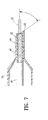
図7は、他の実施例の縦断面を図示しており、バルーンカテーテル10のくさび形の外側シースは、(図1の実施例におけるくさび形のバルーン遠位側スカート部分21の代わりに)くさび形の外側スリーブ部材40となっている。図7の実施例において、バルーン19は円筒状の遠位側スカート部分41を有しており、その直角に切断された遠位側先頭表面は、くさび形の外側スリーブ部材40の近位端に当接している。図1の実施例と同様に、くさび形のスリーブ部材40は、シャフトの軸線に対してある角度をなしてテーパ状なくさび形状を形成する、テーパ状の遠位側先頭表面を有している。
FIG. 7 illustrates a longitudinal section of another embodiment, wherein the wedge-shaped outer sheath of the
図7の実施例において、シャフトの遠位端は、くさび形の外側スリーブ部材40の遠位端より近位側に配置されている。図1の実施例の柔軟な先端部材24は省略されていて、内側管状部材15がシャフトの遠位端を形成している。図7の実施例において、内側管状部材15の遠位端は、くさび形遠位側先頭表面の近位端42より近位側の位置から、くさび形遠位側先頭表面の遠位端43より近位側の位置へと延びていて(すなわち、内側管状部材15の遠位端は、外側スリーブ部材40のくさび形遠位側先頭表面の近位端42と遠位端43との間に配置されていて)、内側管状部材の遠位端の一部のみがくさび形外側スリーブ部材40の角度が付けられている端部を通って延びている。内側管状部材の遠位端がくさび形遠位側先頭表面の近位端42と遠位端43との間に配置されていることにより、内側管状部材15の遠位端は、外側スリーブ部材40によって支持されてはいるもののそれによって部分的に囲まれているだけである。しかしなから、図1の実施例に関して上述したように、くさび形外側スリーブ部材40の遠位端は、他の実施例において、内側管状部材15の遠位端に対して長手方向の様々な位置に配置することができる。例えば、一つの実施例において、内側管状部材15の遠位端は、くさび形外側スリーブ部材40の遠位端43にあり(すなわち、内側管状部材15の遠位端は図7における位置よりもわずかに遠位側にあり)、それらの遠位端は半径方向に位置合わせされる。
In the embodiment of FIG. 7, the distal end of the shaft is located proximal to the distal end of the wedge-shaped
外側スリーブ部材40およびバルーンの遠位側スカート部分41は、図1の実施例に関して上述したように、内側管状部材15に取り付けられている。外側スリーブ部材40は、熱収縮性ポリマー材料から形成して内側管状部材15上に熱収縮させることもできるが、典型的には内側管状部材15に溶着される。
外側スリーブ部材40は、典型的に、約1〜約3ミリメートルの長さを有する。外側スリーブ部材40のくさび形遠位側先頭表面の長さおよび角度は、図1の実施例における遠位側スカート部分21のくさび形遠位側先頭表面のそれと同様である。同様に、図7には鋭利な、テーパ状でない外側表面が図示されているが、図1の実施例に関して上述したように、バルーン19およびスリーブ部材40を内側管状部材15に熱溶着した後に、外側スリーブ部材40および/またはバルーンの遠位側スカート部分41が典型的にテーパ状の外側表面を有することになることは理解されるべきである。加えて、図示されてはいないが、くさび形外側スリーブ部材40を有している実施例においては、先端部材24のような遠位側先端部材を配設することができ、例えば内側管状部材15の遠位端に先端部材(図示せず)を突合せて接合するとともに、突合せ接合した部分をくさび形の外側スリーブ部材40によって密封的に取り囲むことができる。
The
本願明細書において前述しない範囲において、様々なカテーテル構成部品を従来通りの材料および方法によって形成しかつ接続することができる。例えば、内側管状部材15は、血管内カテーテルにおいて有用であることが見い出されたポリエチレン、ポリ塩化ビニル、ポリエステル、ポリアミド、ポリイミド、ポリウレタン、複合材料のような材料を押出加工および口締加工することにより従来技術によって形成することができ、かつ好ましくは多層の管状部材である。加えて、図示されてはいないが、従来知られていているように、巻かれあるいは編まれた補強材料をシャフトの様々な位置に含めることができる。
To the extent not previously described herein, various catheter components can be formed and connected by conventional materials and methods. For example, the
拡張カテーテル10の長さは、経皮経管冠動脈形成術においては、一般的に、約108〜約200センチメートル、好ましくは約137〜約145センチメートル、典型的には約140センチメートルである。外側管状部材14の遠位側部分は約0.028〜約0.036インチ(0.70〜0.91ミリメートル)の外径(OD)および約0.024〜約0.035インチ(0.60〜0.89ミリメートル)の内径(ID)を有し、かつ外側管状部材14の近位側部分は約0.017〜約0.034インチ(0.43〜0.87ミリメートル)の外径および約0.012〜約0.022インチ(0.30〜0.56ミリメートル)の内径を有する。内側管状部材15は、カテーテルと共に使用するガイドワイヤの直径に応じて、約0.017〜約0.026インチ(0.43〜0.66ミリメートルの外径および約0.015〜約0.018インチ(0.38〜0.46ミリメートル)の内径を有する。バルーン19は、約8ミリメートル〜約40ミリメートルの長さ、および約1.5ミリメートル〜約5ミリメートルの膨張有効外径を有する。
The length of the
本願明細書においては特定の好ましい実施例について本発明を説明したが、本発明の範囲内において修正および改良をなしうることは当業者が理解するところである。例えば、図示されたカテーテル10はオーバーザワイヤバルーンカテーテルであるが、本発明のカテーテルは、シャフトの近位端より遠位側に配置されたガイドワイヤ近位側ポート、シャフトの遠位端にあるガイドワイヤ遠位側ポート、およびそれらの間で延びる比較的短いガイドワイヤ管腔を有した迅速交換タイプのバルーンカテーテルを含む、様々な適切なバルーンカテーテルとすることができる。主にくさび形の遠位側スカート部分に関して議論したが、バルーンが、くさび形の近位側スカート部分あるいはスリーブ部材を有することができることは理解されるべきである。本発明の一つの実施例における個々の特徴を、その一つの実施例の図面に示しつかつ議論し、他の実施例においてはそうしないこともできるが、一つの実施例の個々の特徴を他の実施例における一つ若しくは複数の特徴、あるいは複数の実施例の特徴と組み合わせることができることは明らかである。
Although the present invention has been described herein with reference to certain preferred embodiments, those skilled in the art will recognize that modifications and improvements can be made within the scope of the present invention. For example, the illustrated
Claims (25)
b)前記シャフトの少なくとも一つの管腔と流体連通している内部を有した、遠位側シャフト部分上にある膨張可能なバルーンと、
を備えることを特徴とするバルーンカテーテル。 a) an elongate shaft having a proximal end, a distal end and at least one lumen, the distal portion of which is inside an outer sheath having a wedge-shaped distal end;
b) an inflatable balloon on the distal shaft portion having an interior in fluid communication with at least one lumen of the shaft;
A balloon catheter comprising:
前記シャフトが、前記膨張用管腔を画成する外側管状部材と、ガイドワイヤの少なくとも一部を受け入れる管腔を画成する内側管状部材とを有していることを特徴とする請求項1に記載のカテーテル。 At least one lumen of the shaft is an inflation lumen;
2. The shaft of claim 1, wherein the shaft includes an outer tubular member defining the inflation lumen and an inner tubular member defining a lumen for receiving at least a portion of the guide wire. The catheter described.
前記遠位側先端部材が前記シャフトの遠位端を形成していることを特徴とする請求項5に記載したカテーテル。 The shaft has at least a portion distal to the inner tubular member and is in fluid communication with a portion of the guidewire lumen defined by the inner tubular member. A distal tip member defining a portion;
The catheter of claim 5, wherein the distal tip member forms the distal end of the shaft.
前記外側シースは、このくさび形遠位側先頭表面よりも近位側に円筒部分を有していることを特徴とする請求項1に記載のカテーテル。 The distal end of the outer sheath has a wedge-shaped distal leading surface having a proximal end, a distal end, and a length extending about 2.5-4 millimeters from a position proximal to the distal end. Formed,
The catheter according to claim 1, wherein the outer sheath has a cylindrical portion proximal to the wedge-shaped distal leading surface.
b)前記膨張用管腔と流体的に連通している内部を有するとともに、くさび形の遠位端を具備して前記シャフトの遠位側部分に接合される遠位側スカート部分を有している、遠位側シャフト部分上の膨張可能なバルーンと、
を備えることを特徴とするバルーンカテーテル。 a) an elongate shaft having a proximal end, a distal end, an inflation lumen and a guidewire receiving lumen;
b) having a distal skirt portion having an interior in fluid communication with the inflation lumen and having a wedge-shaped distal end joined to the distal portion of the shaft; An inflatable balloon on the distal shaft portion;
A balloon catheter comprising:
前記バルーンの遠位側スカート部分が前記内側管状部材を囲んでいることを特徴とする請求項15に記載のカテーテル。 The shaft is inside an outer tubular member defining the inflation lumen and at least a portion of a distal portion of the inflation lumen and defines at least a portion of a guidewire receiving lumen An inner tubular member,
The catheter of claim 15, wherein a distal skirt portion of the balloon surrounds the inner tubular member.
前記遠位側先端部材は、前記内側管状部材より遠位側の部分を少なくとも有するとともに前記内側管状部材によって画成された前記ガイドワイヤ管腔の一部と流体連通している前記ガイドワイヤ管腔の遠位側部分を画成していることを特徴とする請求項16に記載のカテーテル。 The shaft has a distal tip member forming a distal portion thereof;
The distal tip member has at least a portion distal to the inner tubular member and is in fluid communication with a portion of the guidewire lumen defined by the inner tubular member The catheter of claim 16, wherein the catheter defines a distal portion thereof.
前記バルーンの遠位側スカート部分がこの隙間を囲んでいることを特徴とする請求項19に記載のカテーテル。 The distal tip member is spaced from the distal end of the inner tubular member to form a gap therebetween;
The catheter of claim 19, wherein a distal skirt portion of the balloon surrounds the gap.
a)くさび形の遠位端とカテーテルシャフトの遠位側部分をその内部に受け入れるように構成された管腔とを具備した遠位側スカート部分を有しているバルーンを形成する段階と、
b)前記カテーテルシャフトの遠位側部分を前記遠位側スカート部分の管腔内に配置しる段階と、
c)前記バルーンが前記シャフトの膨張用管腔と流体的に連通する内部を有するように、前記バルーンの遠位側スカート部分の少なくとも一部を前記シャフトの遠位側部分に接合して前記バルーンを前記シャフトに固定する段階と、
を備えることを特徴とする方法。 A method of manufacturing a balloon catheter, comprising:
a) forming a balloon having a distal skirt portion with a wedge-shaped distal end and a lumen configured to receive a distal portion of the catheter shaft therein;
b) positioning the distal portion of the catheter shaft within the lumen of the distal skirt portion;
c) joining at least a portion of the distal skirt portion of the balloon to the distal portion of the shaft such that the balloon has an interior in fluid communication with the inflation lumen of the shaft; Fixing to the shaft;
A method comprising the steps of:
Applications Claiming Priority (2)
| Application Number | Priority Date | Filing Date | Title |
|---|---|---|---|
| US10/318,577 US7141059B2 (en) | 2002-12-12 | 2002-12-12 | Balloon catheter having a flexible distal end |
| PCT/US2003/039229 WO2004054651A2 (en) | 2002-12-12 | 2003-12-09 | Balloon catheter having a flexible distal end |
Publications (1)
| Publication Number | Publication Date |
|---|---|
| JP2006509586A true JP2006509586A (en) | 2006-03-23 |
Family
ID=32506396
Family Applications (1)
| Application Number | Title | Priority Date | Filing Date |
|---|---|---|---|
| JP2004560748A Pending JP2006509586A (en) | 2002-12-12 | 2003-12-09 | Balloon catheter with flexible distal end |
Country Status (7)
| Country | Link |
|---|---|
| US (3) | US7141059B2 (en) |
| EP (1) | EP1578475B1 (en) |
| JP (1) | JP2006509586A (en) |
| AT (1) | ATE422932T1 (en) |
| AU (1) | AU2003296433A1 (en) |
| DE (1) | DE60326276D1 (en) |
| WO (1) | WO2004054651A2 (en) |
Cited By (2)
| Publication number | Priority date | Publication date | Assignee | Title |
|---|---|---|---|---|
| JP2010524572A (en) * | 2007-04-20 | 2010-07-22 | アボット、カーディオバスキュラー、システムズ、インコーポレーテッド | Catheter with multi-layer soft tip that can be easily bonded |
| JP2014208297A (en) * | 2009-06-08 | 2014-11-06 | トライレム メディカル, インコーポレイテッド | Side branch balloon |
Families Citing this family (28)
| Publication number | Priority date | Publication date | Assignee | Title |
|---|---|---|---|---|
| US6863678B2 (en) | 2001-09-19 | 2005-03-08 | Advanced Cardiovascular Systems, Inc. | Catheter with a multilayered shaft section having a polyimide layer |
| US8252014B2 (en) | 2004-03-03 | 2012-08-28 | Innovational Holdings Llc. | Rapid exchange balloon catheter with braided shaft |
| US20050288579A1 (en) * | 2004-06-08 | 2005-12-29 | Miller Stuart H | Sheath |
| US8034031B2 (en) * | 2004-06-08 | 2011-10-11 | Miller Stuart H | Sheath |
| US8043264B2 (en) * | 2004-06-08 | 2011-10-25 | Miller Stuart H | Sheath |
| US8298179B2 (en) * | 2004-12-22 | 2012-10-30 | Boston Scientific Scimed, Inc. | Catheter assembly with tapered joints and method of manufacture |
| US8021386B2 (en) | 2005-03-16 | 2011-09-20 | Gore Enterprise Holdings, Inc. | Controlled release mechanism for balloon catheters |
| WO2006138741A1 (en) | 2005-06-17 | 2006-12-28 | Abbott Laboratories | Method of reducing rigidity of angioplasty balloon sections |
| US7906066B2 (en) | 2006-06-30 | 2011-03-15 | Abbott Cardiovascular Systems, Inc. | Method of making a balloon catheter shaft having high strength and flexibility |
| US8382738B2 (en) | 2006-06-30 | 2013-02-26 | Abbott Cardiovascular Systems, Inc. | Balloon catheter tapered shaft having high strength and flexibility and method of making same |
| US8403885B2 (en) | 2007-12-17 | 2013-03-26 | Abbott Cardiovascular Systems Inc. | Catheter having transitioning shaft segments |
| US8444608B2 (en) | 2008-11-26 | 2013-05-21 | Abbott Cardivascular Systems, Inc. | Robust catheter tubing |
| US8052638B2 (en) | 2008-11-26 | 2011-11-08 | Abbott Cardiovascular Systems, Inc. | Robust multi-layer balloon |
| US8475522B2 (en) | 2009-07-14 | 2013-07-02 | Edwards Lifesciences Corporation | Transapical delivery system for heart valves |
| EP2688631B1 (en) * | 2011-03-25 | 2021-12-01 | Nordson Corporation | Apparatus and methods for accessing and dilating bone structures using a narrow gauge cannula |
| CN107096111A (en) | 2011-05-26 | 2017-08-29 | 雅培心血管系统有限公司 | The conduit of thin hypotube is cut with stairstepping |
| US10406329B2 (en) | 2011-05-26 | 2019-09-10 | Abbott Cardiovascular Systems, Inc. | Through tip for catheter |
| US8449565B2 (en) | 2011-07-21 | 2013-05-28 | Francis Duhay | Approaches to venous occlusion for embolus management |
| US8684963B2 (en) | 2012-07-05 | 2014-04-01 | Abbott Cardiovascular Systems Inc. | Catheter with a dual lumen monolithic shaft |
| US8840743B2 (en) * | 2012-09-11 | 2014-09-23 | Abbott Cardiovascular Systems Inc. | Soft tip balloon catheter |
| WO2014144467A1 (en) | 2013-03-15 | 2014-09-18 | Abbott Cardiovascular Systems Inc. | Reduced material tip for catheter and method of forming same |
| EP2968681A1 (en) | 2013-03-15 | 2016-01-20 | Abbott Cardiovascular Systems Inc. | Catheter shaft and method of forming same |
| CN205287203U (en) | 2014-09-04 | 2016-06-08 | 雅培心血管系统有限公司 | Utricule pipe |
| CR20150461A (en) | 2014-09-04 | 2015-12-14 | BALL CATHETER | |
| CN205360216U (en) | 2015-05-19 | 2016-07-06 | 雅培心血管系统有限公司 | Utricule pipe |
| JP2016214821A (en) | 2015-05-19 | 2016-12-22 | アボット カーディオバスキュラー システムズ インコーポレイテッド | Catheter having monolithic multilayer distal outer member |
| US10842974B2 (en) | 2015-08-17 | 2020-11-24 | Tufts Medical Center, Inc. | Systems and methods for selectively occluding the superior vena cava for treating heart conditions |
| US11872361B2 (en) | 2015-08-17 | 2024-01-16 | Tufts Medical Center, Inc. | Systems and methods for selectively occluding the superior vena cava for treating heart conditions |
Citations (7)
| Publication number | Priority date | Publication date | Assignee | Title |
|---|---|---|---|---|
| JPH07231941A (en) * | 1994-02-24 | 1995-09-05 | Nippon Zeon Co Ltd | Balloon catheter for expanding body cavity |
| US6206852B1 (en) * | 1999-12-15 | 2001-03-27 | Advanced Cardiovascular Systems, Inc. | Balloon catheter having a small profile catheter |
| EP1103280A1 (en) * | 1999-11-26 | 2001-05-30 | Smiths Industries Public Limited Company | Cuffed medico-surgical tubes |
| US6368301B1 (en) * | 1999-12-21 | 2002-04-09 | Advanced Cardiovascular Systems, Inc. | Catheter having a soft distal tip |
| JP2002239009A (en) * | 2001-02-22 | 2002-08-27 | Terumo Corp | Balloon catheter and method of manufacturing balloon catheter |
| JP2002291898A (en) * | 2001-03-29 | 2002-10-08 | Nippon Zeon Co Ltd | Balloon catheter and method for manufacturing the same |
| JP2005538744A (en) * | 2001-10-24 | 2005-12-22 | ボストン サイエンティフィック リミテッド | Material relief of balloon neck constriction and manufacturing method |
Family Cites Families (24)
| Publication number | Priority date | Publication date | Assignee | Title |
|---|---|---|---|---|
| US3890976A (en) | 1972-10-26 | 1975-06-24 | Medical Products Corp | Catheter tip assembly |
| US4894051A (en) | 1984-05-14 | 1990-01-16 | Surgical Systems & Instruments, Inc. | Atherectomy system with a biasing sleeve and method of using the same |
| US4921483A (en) | 1985-12-19 | 1990-05-01 | Leocor, Inc. | Angioplasty catheter |
| US4850960A (en) * | 1987-07-08 | 1989-07-25 | Joseph Grayzel | Diagonally tapered, bevelled tip introducing catheter and sheath and method for insertion |
| US5032113A (en) * | 1989-04-13 | 1991-07-16 | Scimed Life Systems, Inc. | Innerless catheter |
| US4990138A (en) | 1989-07-18 | 1991-02-05 | Baxter International Inc. | Catheter apparatus, and compositions useful for producing same |
| US5057083A (en) | 1989-07-25 | 1991-10-15 | C. R. Bard, Inc. | Vascular dilator with truncated tip |
| US5395330A (en) | 1990-06-13 | 1995-03-07 | Dlp, Inc. | Auto-inflating catheter cuff |
| JPH09507391A (en) * | 1991-07-24 | 1997-07-29 | アドヴァンスト・カーディオヴァスキュラー・システムズ・インコーポレイテッド | Low profile perfusion dilatation catheter |
| US5304134A (en) * | 1992-01-17 | 1994-04-19 | Danforth Biomedical, Inc. | Lubricious yet bondable catheter channel sleeve for over-the-wire catheters |
| US5256145A (en) * | 1992-03-17 | 1993-10-26 | Scimed Life Systems, Inc. | Dilatation catheter strain relief assembly |
| US5649909A (en) * | 1992-04-06 | 1997-07-22 | Scimed Life Systems, Inc. | Variable stiffness multi-lumen catheter |
| US5653690A (en) | 1992-12-30 | 1997-08-05 | Medtronic, Inc. | Catheter having a balloon with retention enhancement |
| US5591129A (en) * | 1994-03-02 | 1997-01-07 | Scimed Life Systems, Inc. | Perfusion balloon angioplasty catheter |
| US5549552A (en) * | 1995-03-02 | 1996-08-27 | Scimed Life Systems, Inc. | Balloon dilation catheter with improved pushability, trackability and crossability |
| US5643209A (en) | 1995-12-15 | 1997-07-01 | Medtronic, Inc. | High pressure balloon tip |
| CA2209366C (en) | 1996-09-13 | 2004-11-02 | Interventional Technologies, Inc. | Incisor-dilator with tapered balloon |
| US6139525A (en) * | 1997-07-08 | 2000-10-31 | Advanced Cardiovascular Systems, Inc. | Fusion bonding of catheter components |
| US6165195A (en) * | 1997-08-13 | 2000-12-26 | Advanced Cardiovascylar Systems, Inc. | Stent and catheter assembly and method for treating bifurcations |
| US6165152A (en) | 1998-09-11 | 2000-12-26 | Advanced Cardiovascular Systems, Inc. | Catheter with a flexible tip and taper and method of manufacture |
| US6193686B1 (en) * | 1999-06-30 | 2001-02-27 | Advanced Cardiovascular Systems, Inc. | Catheter with enhanced flexibility |
| JP4140674B2 (en) * | 1999-09-27 | 2008-08-27 | 東京エレクトロン株式会社 | Method and apparatus for observing porous amorphous film |
| US6364894B1 (en) * | 2000-06-12 | 2002-04-02 | Cordis Corporation | Method of making an angioplasty balloon catheter |
| US6979342B2 (en) * | 2001-09-19 | 2005-12-27 | Advanced Cardiovascular Systems, Incc | Catheter with a polyimide distal tip |
-
2002
- 2002-12-12 US US10/318,577 patent/US7141059B2/en not_active Expired - Lifetime
-
2003
- 2003-12-09 EP EP03813365A patent/EP1578475B1/en not_active Expired - Lifetime
- 2003-12-09 WO PCT/US2003/039229 patent/WO2004054651A2/en active Application Filing
- 2003-12-09 AT AT03813365T patent/ATE422932T1/en not_active IP Right Cessation
- 2003-12-09 AU AU2003296433A patent/AU2003296433A1/en not_active Abandoned
- 2003-12-09 DE DE60326276T patent/DE60326276D1/en not_active Expired - Lifetime
- 2003-12-09 JP JP2004560748A patent/JP2006509586A/en active Pending
-
2006
- 2006-10-24 US US11/585,487 patent/US7771449B2/en not_active Expired - Fee Related
- 2006-10-24 US US11/585,488 patent/US7951259B2/en not_active Expired - Fee Related
Patent Citations (7)
| Publication number | Priority date | Publication date | Assignee | Title |
|---|---|---|---|---|
| JPH07231941A (en) * | 1994-02-24 | 1995-09-05 | Nippon Zeon Co Ltd | Balloon catheter for expanding body cavity |
| EP1103280A1 (en) * | 1999-11-26 | 2001-05-30 | Smiths Industries Public Limited Company | Cuffed medico-surgical tubes |
| US6206852B1 (en) * | 1999-12-15 | 2001-03-27 | Advanced Cardiovascular Systems, Inc. | Balloon catheter having a small profile catheter |
| US6368301B1 (en) * | 1999-12-21 | 2002-04-09 | Advanced Cardiovascular Systems, Inc. | Catheter having a soft distal tip |
| JP2002239009A (en) * | 2001-02-22 | 2002-08-27 | Terumo Corp | Balloon catheter and method of manufacturing balloon catheter |
| JP2002291898A (en) * | 2001-03-29 | 2002-10-08 | Nippon Zeon Co Ltd | Balloon catheter and method for manufacturing the same |
| JP2005538744A (en) * | 2001-10-24 | 2005-12-22 | ボストン サイエンティフィック リミテッド | Material relief of balloon neck constriction and manufacturing method |
Cited By (2)
| Publication number | Priority date | Publication date | Assignee | Title |
|---|---|---|---|---|
| JP2010524572A (en) * | 2007-04-20 | 2010-07-22 | アボット、カーディオバスキュラー、システムズ、インコーポレーテッド | Catheter with multi-layer soft tip that can be easily bonded |
| JP2014208297A (en) * | 2009-06-08 | 2014-11-06 | トライレム メディカル, インコーポレイテッド | Side branch balloon |
Also Published As
| Publication number | Publication date |
|---|---|
| AU2003296433A1 (en) | 2004-07-09 |
| EP1578475B1 (en) | 2009-02-18 |
| US7951259B2 (en) | 2011-05-31 |
| EP1578475A2 (en) | 2005-09-28 |
| US20040116956A1 (en) | 2004-06-17 |
| US20070073330A1 (en) | 2007-03-29 |
| WO2004054651A2 (en) | 2004-07-01 |
| WO2004054651A3 (en) | 2004-09-02 |
| US20070066989A1 (en) | 2007-03-22 |
| DE60326276D1 (en) | 2009-04-02 |
| US7141059B2 (en) | 2006-11-28 |
| AU2003296433A8 (en) | 2004-07-09 |
| US7771449B2 (en) | 2010-08-10 |
| ATE422932T1 (en) | 2009-03-15 |
Similar Documents
| Publication | Publication Date | Title |
|---|---|---|
| US7951259B2 (en) | Balloon catheter having a flexible distal end | |
| EP2148715B1 (en) | Catheter having a readily bondable multilayer soft tip | |
| US6692461B2 (en) | Catheter tip | |
| US7967781B2 (en) | Rapid exchange balloon catheter having a reinforced inner tubular member | |
| US6837870B2 (en) | Catheter having a multilayered shaft section with a reinforcing mandrel | |
| JP4813003B2 (en) | Catheter with improved transition portion | |
| US6575934B2 (en) | Low profile catheter | |
| JP6706889B2 (en) | Balloon catheter | |
| WO2003075996A1 (en) | Balloon catheter for tentative vaso-occlusion | |
| JP6706888B2 (en) | Balloon catheter | |
| JP2016214820A (en) | Balloon catheter | |
| US7115137B2 (en) | Balloon catheter having a balloon distal skirt section with a reduced outer diameter secured to a soft distal tip member | |
| US20030032921A1 (en) | Catheter having a tapered tip | |
| US20030163118A1 (en) | Catheter having a tapered distal tip and method of making | |
| US6881201B1 (en) | Balloon catheter having a spiral cut distal end |
Legal Events
| Date | Code | Title | Description |
|---|---|---|---|
| A621 | Written request for application examination |
Free format text: JAPANESE INTERMEDIATE CODE: A621 Effective date: 20061211 |
|
| A977 | Report on retrieval |
Free format text: JAPANESE INTERMEDIATE CODE: A971007 Effective date: 20091029 |
|
| A131 | Notification of reasons for refusal |
Free format text: JAPANESE INTERMEDIATE CODE: A131 Effective date: 20091117 |
|
| A02 | Decision of refusal |
Free format text: JAPANESE INTERMEDIATE CODE: A02 Effective date: 20100413 |