JP2006507837A - Biological growth plate scanner with automatic image processing profile selection - Google Patents
Biological growth plate scanner with automatic image processing profile selection Download PDFInfo
- Publication number
- JP2006507837A JP2006507837A JP2004557258A JP2004557258A JP2006507837A JP 2006507837 A JP2006507837 A JP 2006507837A JP 2004557258 A JP2004557258 A JP 2004557258A JP 2004557258 A JP2004557258 A JP 2004557258A JP 2006507837 A JP2006507837 A JP 2006507837A
- Authority
- JP
- Japan
- Prior art keywords
- plate
- image processing
- biological growth
- image
- biological
- Prior art date
- Legal status (The legal status is an assumption and is not a legal conclusion. Google has not performed a legal analysis and makes no representation as to the accuracy of the status listed.)
- Pending
Links
Images


Classifications
-
- G—PHYSICS
- G06—COMPUTING; CALCULATING OR COUNTING
- G06T—IMAGE DATA PROCESSING OR GENERATION, IN GENERAL
- G06T7/00—Image analysis
- G06T7/0002—Inspection of images, e.g. flaw detection
- G06T7/0012—Biomedical image inspection
-
- G—PHYSICS
- G06—COMPUTING; CALCULATING OR COUNTING
- G06F—ELECTRIC DIGITAL DATA PROCESSING
- G06F18/00—Pattern recognition
-
- C—CHEMISTRY; METALLURGY
- C12—BIOCHEMISTRY; BEER; SPIRITS; WINE; VINEGAR; MICROBIOLOGY; ENZYMOLOGY; MUTATION OR GENETIC ENGINEERING
- C12M—APPARATUS FOR ENZYMOLOGY OR MICROBIOLOGY; APPARATUS FOR CULTURING MICROORGANISMS FOR PRODUCING BIOMASS, FOR GROWING CELLS OR FOR OBTAINING FERMENTATION OR METABOLIC PRODUCTS, i.e. BIOREACTORS OR FERMENTERS
- C12M41/00—Means for regulation, monitoring, measurement or control, e.g. flow regulation
- C12M41/30—Means for regulation, monitoring, measurement or control, e.g. flow regulation of concentration
- C12M41/36—Means for regulation, monitoring, measurement or control, e.g. flow regulation of concentration of biomass, e.g. colony counters or by turbidity measurements
-
- G—PHYSICS
- G06—COMPUTING; CALCULATING OR COUNTING
- G06V—IMAGE OR VIDEO RECOGNITION OR UNDERSTANDING
- G06V10/00—Arrangements for image or video recognition or understanding
- G06V10/10—Image acquisition
-
- G—PHYSICS
- G06—COMPUTING; CALCULATING OR COUNTING
- G06V—IMAGE OR VIDEO RECOGNITION OR UNDERSTANDING
- G06V20/00—Scenes; Scene-specific elements
- G06V20/60—Type of objects
- G06V20/69—Microscopic objects, e.g. biological cells or cellular parts
-
- G—PHYSICS
- G06—COMPUTING; CALCULATING OR COUNTING
- G06T—IMAGE DATA PROCESSING OR GENERATION, IN GENERAL
- G06T2207/00—Indexing scheme for image analysis or image enhancement
- G06T2207/30—Subject of image; Context of image processing
- G06T2207/30004—Biomedical image processing
- G06T2207/30024—Cell structures in vitro; Tissue sections in vitro
Abstract
Description
技術分野
本発明は、食品試料、実験用試料等内の細菌または他の生物剤を分析する生物成長培地の分析のための技術に関する。
TECHNICAL FIELD The present invention relates to techniques for analysis of biological growth media that analyze bacteria or other biological agents in food samples, laboratory samples, and the like.
背景技術
生物学的安全性は近代社会における重大な関心事である。食品または他の材料内の生物汚染の試験は、食品の開発者および販売者にとって重要且つ時には義務要件になってきている。また生物試験を利用して医療患者から採取した血液試料などの実験用試料、実験目的に開発された実験用試料、および他のタイプの生物試料内の細菌または他の物質を識別する。様々な技術および装置を利用して生物試験を改善するとともに、生物試験プロセスを簡素化および標準化することができる。
Background Art Biological safety is a major concern in modern society. Testing for biocontamination in food or other materials has become an important and sometimes mandatory requirement for food developers and distributors. Biological tests are also used to identify laboratory samples such as blood samples taken from medical patients, laboratory samples developed for experimental purposes, and bacteria or other substances in other types of biological samples. Various techniques and devices can be utilized to improve biological testing and simplify and standardize biological testing processes.
具体的には多様な生物成長培地が開発されてきた。一例として成長プレートの形状の生物成長培地がミネソタ州セントポール(St.Paul,Minnesota)のスリーエム・カンパニー(3M Company)(以下「3M」)により開発された。生物成長プレートは商品名ペトリフィルム(PETRIFILM)プレートで3Mにより販売されている。生物成長プレートを利用することにより、例えば好気性細菌、大腸菌(E.coli)、大腸菌型、腸内細菌科、酵母菌、糸状菌、黄色ブドウ球菌、リステリア、およびカンピロバクター等を始めとする、通常食品汚染に関連する細菌または他の生物剤の迅速な成長および検出または測定を容易にすることができる。ペトリフィルム(PETRIFILM)プレートまたは他の成長培地を利用することにより、食品試料の細菌試験を単純化することができる。 Specifically, various biological growth media have been developed. As an example, a growth medium in the form of a growth plate was developed by the 3M Company (hereinafter "3M") of St. Paul, Minnesota. The biological growth plate is sold by 3M under the trade name Petrifilm plate. By using a biological growth plate, for example, aerobic bacteria, E. coli, E. coli type, Enterobacteriaceae, yeast, filamentous fungus, Staphylococcus aureus, Listeria, Campylobacter, etc. Rapid growth and detection or measurement of bacteria or other biological agents associated with food contamination can be facilitated. By utilizing Petrifilm (PETRIFILM) plates or other growth media, bacterial testing of food samples can be simplified.
生物成長培地を用いて細菌の存在を識別することができるため、補正措置を行う(食品試験の場合)かまたは適正な診断を行う(医療用途の場合)ことができる。他の用途においては生物成長培地を用いて例えば実験目的用の実験用試料内の細菌または生物剤を迅速に成長し得る。 Because the growth medium can be used to identify the presence of bacteria, corrective action can be taken (for food testing) or a proper diagnosis can be made (for medical use). In other applications, biological growth media can be used to rapidly grow bacteria or biological agents, for example, in laboratory samples for experimental purposes.
生物スキャナとは生物成長培地上の細菌コロニーまたは特定の生物剤の量を読み取るまたは計数するために用いる装置を指す。例えば食品試料または実験用試料を生物成長培地上に置いて、その後その培地を培養室内に挿入することができる。培養後、生物成長培地を生物スキャナ内に配置して細菌成長を自動検出および測定することができる。換言すれば生物スキャナは生物成長培地上の細菌または他の生物剤の検出および測定を自動化することにより、人為ミスを低減することによって生物試験プロセスを改善する。 A biological scanner refers to a device used to read or count the amount of bacterial colonies or specific biological agents on a biological growth medium. For example, food samples or experimental samples can be placed on a biological growth medium, which can then be inserted into the culture chamber. After incubation, the biological growth medium can be placed in a biological scanner to automatically detect and measure bacterial growth. In other words, the biological scanner improves the biological testing process by reducing human error by automating the detection and measurement of bacteria or other biological agents on the biological growth medium.
発明の概要
一般に本発明は、異なるタイプの生物成長プレートを走査および分析するために画像処理プロファイルの選択を自動化する生物スキャナに関する。このスキャナは被走査プレートのタイプを自動的に識別した後、識別されたプレートタイプに適合する画像処理プロファイルのうちの1つを選択する。
SUMMARY OF THE INVENTION Generally, the present invention relates to a biological scanner that automates the selection of image processing profiles for scanning and analyzing different types of biological growth plates. The scanner automatically identifies the type of plate to be scanned and then selects one of the image processing profiles that matches the identified plate type.
スキャナはプレートに担持された光学的または磁気的に読取可能なマークなどの様々な機械可読標識を参照することによりプレートタイプを識別し得る。従って本発明は画像処理プロファイルの選択のためのプレートタイプ識別を可能にする特定の標識を担持する生物成長プレートにも関する。 The scanner may identify the plate type by referring to various machine readable signs such as optically or magnetically readable marks carried on the plate. Accordingly, the present invention also relates to a biological growth plate carrying a specific label that allows plate type identification for selection of an image processing profile.
プレートを走査して生物成長プレート上の異なるタイプの細菌コロニー、または特定の生物剤の量を読み取るまたは計数し得る。動作中、例えば生物成長プレートをスキャナに提示するとスキャナはプレートタイプを識別する。その後スキャナは識別されたプレートタイプに関連する画像処理プロファイルに従って画像を処理する。 The plate can be scanned to read or count the amount of different types of bacterial colonies on a biological growth plate, or a specific biological agent. In operation, for example, when a biological growth plate is presented to the scanner, the scanner identifies the plate type. The scanner then processes the image according to the image processing profile associated with the identified plate type.
画像処理プロファイルは、特定のプレートタイプの画像を取り込むための照明強度、継続時間および色などの特定の画像取込条件を指定し得る。また画像取込条件はカメラ利得、解像度、アパーチャ、および露光時間を含み得る。さらに画像処理プロファイルは、取込画像内の異なるタイプの細菌コロニーを検出または測定するために色、形状、サイズおよび近接基準などの特定の画像分析基準を指定し得る。このようにスキャナは生物成長プレートの画像を処理する際に異なる画像取込条件、異なる画像分析基準、またはその両方を適用し得る。 An image processing profile may specify specific image capture conditions such as illumination intensity, duration and color for capturing images of a particular plate type. Image capture conditions can also include camera gain, resolution, aperture, and exposure time. Furthermore, the image processing profile may specify specific image analysis criteria such as color, shape, size and proximity criteria to detect or measure different types of bacterial colonies in the captured image. Thus, the scanner may apply different image capture conditions, different image analysis criteria, or both when processing images of the biological growth plate.
動作中、生物スキャナはプレートタイプを識別すると、対応する画像処理プロファイルを選択し得る。生物スキャナは画像処理プロファイルにより指定された画像取込条件を用いて生物成長プレートを照明するとともに、プレートの1つ以上の画像を取り込み得る。生物スキャナはその後、画像処理プロファイルにより指定された画像分析基準を用いて取込画像の分析を行い得る。このように生物スキャナは異なるタイプの生物成長プレートの走査および分析を自動化する。 In operation, once the biological scanner identifies the plate type, it may select a corresponding image processing profile. The biological scanner can illuminate the biological growth plate using the image capture conditions specified by the image processing profile and capture one or more images of the plate. The biological scanner may then perform an analysis of the captured image using the image analysis criteria specified by the image processing profile. Thus, the biological scanner automates the scanning and analysis of different types of biological growth plates.
一実施形態において本発明は、一組の画像処理プロファイルを記憶するメモリと、生物成長プレートに関連するプレートタイプに基づいて画像処理プロファイルのうちの1つを選択する画像処理装置と、を含む装置を提供する。 In one embodiment, the invention includes a device that includes a memory that stores a set of image processing profiles and an image processing device that selects one of the image processing profiles based on a plate type associated with the biological growth plate. I will provide a.
他の実施形態において本発明は、生物成長プレートに関連するプレートタイプを検出するステップと、検出したプレートタイプに基づいて複数の画像処理プロファイルのうちの1つを選択するステップと、選択した画像処理プロファイルに従って生物成長プレートの画像を処理するステップと、を含む方法を提供する。 In another embodiment, the invention includes detecting a plate type associated with a biological growth plate, selecting one of a plurality of image processing profiles based on the detected plate type, and selected image processing. Processing an image of the biological growth plate according to the profile.
更なる実施形態において本発明は、プロセッサに、生物成長プレートに対して検出されたプレートタイプに基づいて複数の画像処理プロファイルのうちの1つを選択させるとともに、画像処理装置を制御して選択された画像処理プロファイルに従って生物成長プレートの画像を処理させる命令を含むコンピュータ読取可能媒体を提供する。 In a further embodiment, the present invention causes the processor to select one of a plurality of image processing profiles based on the detected plate type for the biological growth plate and to control and select the image processing apparatus. A computer-readable medium is provided that includes instructions for processing an image of a biological growth plate in accordance with the image processing profile.
更なる実施形態において本発明は、生物剤の成長を支援するプレート表面と、生物成長プレートのタイプを識別する機械可読プレートタイプ標識と、を含む生物成長プレートを提供する。 In a further embodiment, the present invention provides a biological growth plate that includes a plate surface that supports the growth of biological agents and a machine readable plate type indicator that identifies the type of biological growth plate.
他の実施形態において本発明は、生物成長プレートのプレートタイプを識別する機械可読プレートタイプ標識を含む生物成長プレートと、生物成長プレートの画像を取り込むとともに、プレートタイプ標識に基づいて選択された複数の画像処理プロファイルのうちの1つに従って画像を処理する撮像装置と、を含むシステムを提供する。 In another embodiment, the present invention captures a biological growth plate that includes a machine readable plate type indicator that identifies a plate type of the biological growth plate, and images of the biological growth plate and a plurality of selected based on the plate type indicator. An imaging device for processing an image according to one of the image processing profiles is provided.
本発明は多数の利点を提供することができる。例えば自動画像処理プロファイル選択は、適当な画像処理プロファイルを選択するための便利で精度の高い技術を提供することができる。自動画像処理プロファイル選択は、細菌コロニー計数および他の分析手順の精度を向上させることにより品質保証を強化することができる。具体的には各プレートタイプに対して適当な画像取込条件および画像分析基準を自動的に選択して適用することができる。自動画像処理プロファイル選択により技術者がプレートタイプを目視で識別して手動で入力する必要性をなくすことができることによって、人間の介入に関連する場合もあるプレート識別エラーをなくすことができる。分析精度は特に食品試料を試験する際に重大な健康上の問題になり得る。さらに自動画像処理プロファイル選択は効率と利便性とを向上させるとともに、実験技術者の作業フローを改善させることができる。生物スキャナによる自動プレートタイプ識別を可能にする機械可読プレートタイプ標識を担持する生物成長プレートは以上の利点に貢献することができる。 The present invention can provide a number of advantages. For example, automatic image processing profile selection can provide a convenient and accurate technique for selecting an appropriate image processing profile. Automatic image processing profile selection can enhance quality assurance by improving the accuracy of bacterial colony counting and other analytical procedures. Specifically, appropriate image capture conditions and image analysis criteria can be automatically selected and applied to each plate type. Automatic image processing profile selection eliminates the need for technicians to visually identify and manually enter plate types, thereby eliminating plate identification errors that may be associated with human intervention. Analytical accuracy can be a significant health problem, especially when testing food samples. Furthermore, automatic image processing profile selection can improve efficiency and convenience and improve the work flow of an experimental engineer. A biological growth plate carrying a machine readable plate type indicator that allows automatic plate type identification by a biological scanner can contribute to these advantages.
これらのおよび他の実施形態の更なる詳細は添付の図面と以下の説明とに記載されている。他の特徴と目的と利点とは明細書および図面からならびに請求の範囲から明らかになろう。 Further details of these and other embodiments are set forth in the accompanying drawings and the description below. Other features, objects, and advantages will be apparent from the description and drawings, and from the claims.
発明の詳細な説明
本発明は生物成長プレート用生物スキャナに関する。生物成長プレートを生物スキャナに提示すると、生物スキャナはプレートの画像を生成するとともに画像の分析を行って生物成長を検出することができる。例えばスキャナは細菌コロニーの数など、画像に現れる生物剤の量を計数あるいは定量し得る。このように生物スキャナは生物成長プレートの分析を自動化することにより、このような分析を改善するとともに人為ミスの可能性を低減する。
The present invention relates to a biological scanner for biological growth plates. When the biological growth plate is presented to the biological scanner, the biological scanner can generate an image of the plate and analyze the image to detect biological growth. For example, the scanner can count or quantify the amount of biological agent that appears in the image, such as the number of bacterial colonies. Thus, the biological scanner improves the analysis and reduces the possibility of human error by automating analysis of the biological growth plate.
また本発明による生物スキャナは、異なるタイプの生物成長プレートを走査するとともにプレート画像を分析するために画像処理プロファイルの選択を自動化する。スキャナはスキャナにより走査されるプレートのタイプを自動的に識別した後、識別したプレートタイプに適した画像処理プロファイルの1つを選択する。画像処理プロファイルは異なるタイプの生物成長プレートに対する画像取込条件、画像分析基準またはその両方の組み合わせを指定し得る。例えば画像処理プロファイルは、画像取込用の特定のプレートタイプの照明強度、継続時間および照明用色を指定し得る。また画像取込条件はカメラ利得、解像度、アパーチャ、および露光時間を含み得る。画像分析基準の点では画像処理プロファイルは、取込画像内の異なるタイプの細菌コロニーを計数する際に異なる色、形状、サイズおよび近接基準を指定することにより、分析結果の精度、例えば計数を向上し得る。そのため画像処理プロファイルは画像取込および分析の両方に関連し得る。精度は食品および実験用試料試験環境の両方において重要である。食品安全性の場合は特に、正確な結果によってライン生産、設備および環境試験を始めとする食品処理動作を通して重要管理点での衛生確認が可能になる。 The biological scanner according to the invention also automates the selection of image processing profiles for scanning different types of biological growth plates and analyzing plate images. After the scanner automatically identifies the type of plate scanned by the scanner, it selects one of the image processing profiles appropriate for the identified plate type. The image processing profile may specify image capture conditions, image analysis criteria, or a combination of both for different types of biological growth plates. For example, an image processing profile may specify a particular plate type illumination intensity, duration, and illumination color for image capture. Image capture conditions can also include camera gain, resolution, aperture, and exposure time. In terms of image analysis criteria, image processing profiles improve the accuracy of analysis results, eg counting, by specifying different colors, shapes, sizes and proximity criteria when counting different types of bacterial colonies in captured images. Can do. As such, the image processing profile can relate to both image capture and analysis. Accuracy is important in both food and laboratory sample testing environments. Especially in the case of food safety, accurate results allow hygiene confirmation at critical control points through food processing operations including line production, equipment and environmental testing.
スキャナは、プレートに担持されている光学的または磁気的読取可能マークなどの様々な機械可読プレートタイプ標識を参照することによりプレートタイプを識別し得る。従って本発明は生物成長プレートがプレートタイプの識別を可能にする特定の標識を担持することも考慮している。さらに本発明はプレートタイプ識別を行う際の人間の判断への依存を排除または減少させることにより、コロニー計数または他の分析の人為ミスおよびその結果生じる不正確さの可能性を低減し得る。 The scanner may identify the plate type by referring to various machine readable plate type indicators such as optical or magnetic readable marks carried on the plate. Thus, the present invention also contemplates that the biological growth plate carries a specific label that allows plate type identification. Furthermore, the present invention may reduce the possibility of colony counting or other analytical human error and the resulting inaccuracy by eliminating or reducing the reliance on human judgment in making plate type identification.
本発明は様々な生物成長プレートに有用であり得る。例えば本発明は薄膜培養プレート装置、ペトリ皿培養プレート装置等など生物剤を成長させる異なるプレート状装置に有用であり、生物剤の検出または測定を可能にし得る。そのため用語「生物成長プレート」を本明細書では広義に用いて、スキャナによる生物剤の検出および測定を可能にする生物剤の成長に適した培地を示す。いくつかの実施形態において、例えばグレースル(Graessle)らに与えられた米国特許第5,573,950号明細書に記載されているように、生物成長プレートを複数のプレートを支持する容器に収容することができる。 The present invention may be useful for a variety of biological growth plates. For example, the present invention is useful for different plate-like devices for growing biological agents, such as thin film culture plate devices, petri dish culture plate devices, etc., and may allow detection or measurement of biological agents. As such, the term “biological growth plate” is used broadly herein to indicate a medium suitable for growth of a biological agent that allows the detection and measurement of the biological agent by a scanner. In some embodiments, the biological growth plate is housed in a container that supports a plurality of plates, as described, for example, in US Pat. No. 5,573,950 to Graessle et al. be able to.
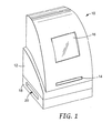
図1は例示的生物スキャナ10の斜視図である。図1に示すように、生物スキャナ10は生物成長プレート(図1には図示せず)を受け取る引出し14を有するスキャナユニット12を含んでいる。引出し14は生物成長プレートを走査および分析用生物スキャナ10内に移動させる。スキャナ10は本発明による自動プレートタイプ識別、およびプレートタイプに基づいた画像処理プロファイルの自動選択を可能にする特徴を組み込み得る。
FIG. 1 is a perspective view of an exemplary
また生物スキャナ10は表示画面16を含み、生物成長プレートの分析の進行または結果をユーザに表示し得る。代替的または追加的に、表示画面は生物スキャナ10により走査された成長プレートの画像をユーザに提示し得る。表示された画像は光学的に拡大またはデジタルに拡大し得る。載置台18は生物スキャナ10による画像取込に続いて成長プレートを排出することができる排出スロット20を規定している。従って生物スキャナ10はスキャナユニット12が載置台18に載置されている2部構成を有し得る。2部構成は例示目的で図1に図示されているが、本明細書に記載された発明に必要としたりまたは発明の限定を意図するものではない。
The
スキャナユニット12は生物成長プレートを走査して画像を生成するための撮像装置を収容している。撮像装置はラインスキャナまたはエリアスキャナの形状を取り、通常生物成長プレートの前面および/または背面照明を提供する照明システムと組み合わせて設けられる。さらにスキャナユニット12は例えば成長プレート内の生物剤の数または量を判定するために、走査画像の分析を行う処理ハードウェアを収容し得る。例えば引出し14を介して生物成長プレートが提示されると、プレートは走査用光学プラテンに隣接して配置され得る。
The
その後引出しが開放されると、成長プレートは載置台18内に下降して排出スロット20を介して排出し得る。そのため載置台18は成長プレートを排出スロット20を介して生物スキャナ10から排出するコンベヤーを収容し得る。生物成長プレートが引出し14内に挿入され、スキャナユニット12内に移動され、走査された後、生物成長プレートは載置台18内に降下し、そこで移動ベルトなどの水平コンベヤーがスロット20を介して培地を排出する。
Thereafter, when the drawer is opened, the growth plate can be lowered into the mounting table 18 and discharged through the
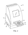
図2は生物スキャナ10の他の斜視図である。図2に示すように引出し14は生物スキャナ10から外側に延出して生物成長プレート22を受け取る。図示のように生物成長プレート22を引出し14内に設けられた台24上に配置し得る。いくつかの実施形態において、台24はカムレバーなどの位置決め作動装置を含み、台を上昇させて生物スキャナ10内に成長プレート22を正確に位置決めし得る。生物成長プレート22を台24上に配置すると、引出し14はスキャナユニット12内に後退して生物成長プレートを走査位置、すなわち生物成長培地が光学的に走査される位置に配置する。
FIG. 2 is another perspective view of the
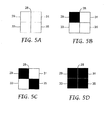
図3および4は例示的生物成長プレート22の平面図である。例として適当な成長プレート22は、商品名ペトリフィルム(PETRIFILM)プレートで3Mにより販売されている生物成長プレートを含み得る。代替的には生物成長プレート22は、特定の細菌または他の生物剤を成長させる他の生物成長培地を含み得る。本発明によれば生物成長プレート22は、成長プレートに関連する生物培地のタイプの自動識別を容易にするプレートタイプ標識28を担持している。
3 and 4 are plan views of an exemplary
プレートタイプ標識28は機械可読である符号化パターンを提示する。図3および4の例において、プレートタイプ標識28は光学的読取可能パターンの形状を取る。具体的には図3および4は、生物成長プレート22の角部余白に形成された明暗四分の一区分の4つの四角形パターンを示す。換言すればプレートタイプ標識28は、符号化パターンを形成する白黒間で変化させたセルの二次元格子を規定する。文字、バーコード、二次元バーコード、光学格子、ホログラム、蛍光インク(phosphorous ink)等などの多様な光学パターンが考えられる。
The
さらにいくつかの実施形態において、プレートタイプ標識28は磁気的または無線技術により読取可能なパターンの形状を取り得る。代替的にはプレートタイプ標識28は、光学的または機械的技術により読取可能なアパーチャ、スロット、表面輪郭等の形状を取り得る。いずれの場合もプレートタイプ標識28は生物スキャナ10による生物成長プレート22のタイプの自動識別を可能にする十分な情報を担持している。プレートタイプ標識28を以下により詳細に説明する。
Further, in some embodiments, the
生物成長プレートは例えば好気性細菌、大腸菌、大腸菌型、腸内細菌科、酵母菌、糸状菌、黄色ブドウ球菌、リステリア、およびカンピロバクター等を始めとする細菌または他の生物剤の迅速な成長および検出ならびに測定を容易にし得る。ペトリフィルムプレートまたは他の成長培地を利用することにより食品試料の細菌試験を単純化することができる。また本明細書において概説するように、生物スキャナ10は自動プレートタイプ検出および検出されたプレートタイプに基づいた画像処理プロファイルの自動選択を提供し、生物成長プレート22を照明および/または例えばプレートの画像上の細菌コロニーを計数して分析することによりこのような試験をさらに単純化することができる。
Biological growth plates are used for rapid growth and detection of bacteria or other biological agents including aerobic bacteria, E. coli, coliforms, Enterobacteriaceae, yeasts, filamentous fungi, Staphylococcus aureus, Listeria, and Campylobacter As well as easy measurement. Utilizing a Petri film plate or other growth medium can simplify the bacterial testing of food samples. Also as outlined herein, the
図3に示すように生物成長プレート22は成長エリア26を規定している。細菌コロニー数に関して、プレート22内で試験されている所与の試料が許容可能か否かの判定は単位面積当たりの細菌コロニーの数による。従ってスキャナ10はプレート22上の単位面積あたりの細菌コロニーの量を定量し得るとともに、その量すなわち「数」を閾値と比較し得る。生物成長プレート22の表面は、1つ以上のタイプの細菌または他の生物剤の迅速な成長を容易にするように構成された1つ以上の成長促進剤を含み得る。
As shown in FIG. 3, the
成長エリア26内の生物成長プレート22の表面上に、概して液状の被験材料の試料を配置した後、プレート22を培養室(図示せず)に挿入することができる。培養室において、図4の生物成長プレート22に示すように成長プレート22により成長する細菌コロニーまたは他の生物剤が出現する。図4の生物成長プレート22上の様々なドット30で表されるコロニーはプレート22上に異なる色で出現し、スキャナ10による細菌コロニーの自動検出および測定を容易にする。
After placing a generally liquid sample of the test material on the surface of the
図5A〜5Dは、画像処理プロファイル選択用に生物成長プレート22により担持される例示的なプレートタイプ標識28を図示する図である。またプレートタイプ標識28は光学的または機械的読取可能性を可能にするパターン、マーク、アパーチャ、表面輪郭等の形状を取り得る。例えば光復号器、バーコードスキャナ、光学式文字識別(OCR)プロセッサ等により異なる光学パターンを読み取ることができる。アパーチャまたは輪郭の場合、機械的な針がアパーチャまたは輪郭と相互作用して異なるパターンを検出して電気信号を生成し得る。代替的にはプレートタイプ標識28は磁気的な符号化ストライプまたはマーカーであり、もしくは無線識別表示を担持して磁気的または無線読取可能性を可能にする。
5A-5D are diagrams illustrating an exemplary
生物成長プレート22の表面上、例えば成長エリア26の外側にインクを印刷または付着させることにより光学的に読取可能なパターンを形成し得る。アパーチャまたは表面輪郭パターンは穿孔、刻印、エンボス、打ち抜き等により、生物成長プレート22内に形成することができる。磁気ストライプまたは無線識別表示を、例えば接着剤または積層技術により生物成長プレート22の表面に貼り付け得る。さらに生物成長プレート22の表面に磁気または無線標識を担持する必要はなく、成長プレートが多層構造を有する場合には成長プレートの層間に介在させ得る。いずれの場合も生物成長プレート22のタイプを識別するために、工場において様々なプレートタイプ標識28を形成し得る。
An optically readable pattern may be formed by printing or depositing ink on the surface of the
さらに必要な場合には、プレートタイプ標識28は、具体的なメーカー、ロット番号、耐用年数、安全認証等を識別する情報をさらに含み得る。このような追加情報項目は、生物スキャナ10で用いる生物成長プレート22の品質および適性を確認する上で重要であり得る。例えば生物スキャナ10で用いる生物成長プレート22を提供するために、例えばプレート製造品質およびプレート性能基準に基づいて、1つ以上のメーカーを特定し得る。この場合プレートタイプ標識28により、認定されたメーカーと関連しない生物成長プレート22を拒絶するように生物スキャナ10を構成し得る。
If further necessary, the
さらにプレートタイプ標識28は、生物成長プレート22を確認するとともに未許可成長プレートの不正導入を防止する、例えば食品検査または実験分析プロセスを阻止する役目をするシリアル番号コード等などの安全情報を担持し得る。このような情報は生物成長プレート22内で一体化および符号化されるが、代替的には成長プレートにより担持される別の標識パターン内で符号化され得る。従って生物成長プレート22はプレートタイプ標識28に加えて、異なる安全性および品質保証の目的を果たす1つ以上の標識パターンを担持し得る。
In addition, the
安全性を高めるために、プレートタイプ標識28、さらに生物成長プレート22により担持し得る任意の他の標識は様々な安全機構の恩恵を蒙ることができる。例えばいくつかの実施形態において印刷されたプレートタイプ標識28が特定の蛍光インクで印刷されているため、走査する際に標識が発する光の波長によりはっきりと識別することができる。さらにプレートタイプ標識28は動作用の生物スキャナ10を解除するための暗号化キーを担持する、より複雑なパターンの形状を取り得る。この場合生物スキャナ10内のプロセッサ34(図6)はパターンの暗合解読を行って画像処理を進行し得る。
To increase safety, the
図5A〜5Dの例において、プレートタイプ標識28は明暗いずれかである4つの四分の一区分29、31、33、35を有する4つの四角形パターンの形状を取り、容易な光学処理を可能にする。図5Aにおいてプレートタイプ標識28は4つの明るい四分の一区分を有し、第1のタイプの生物成長プレート22を識別し得る。図5B、5Cおよび5Dにおいて、プレートタイプ標識28はそれぞれ、1つの黒い四分の一区分、2つの黒い四分の一区分、および4つの黒い四分の一区分を含んでいる。黒い四分の一区分の数および位置の選択は16(24)までの異なる暗号化パターンを形成し、従って16までの異なるプレートタイプを機械可読プレートタイプ標識28によって識別可能にする。例として異なる暗号化パターンは好気性数、大腸菌型、大腸菌、腸内細菌科、酵母菌、糸状菌および他のプレートタイプ名称を表わすこともできる。
In the example of FIGS. 5A-5D, the
プレートタイプ標識28の形状は多様であり得るが、図5A〜5Dに示した4つの四角形パターンは比較的単純且つ光学パターン認証技術、すなわちマシンビジョンを利用して識別容易な1つのタイプのパターンを提供する。説明するように、バーコード読取装置またはカスタム読取装置などの専用の光学コード読取装置によりプレートタイプ標識28を走査し得る。この場合プレートタイプ標識28の走査は、成長プレート画像の処理前以外に生物成長プレート22の走査に先立ってまたは平行して行うことができる。代替的にはプレートタイプ標識28を生物成長プレート22の走査画像に取り込み、その後画像処理のために抽出してプレートタイプを識別し得る。この場合走査した成長プレート画像をさらに画像処理する前にプレートタイプを識別することができる。
Although the shape of the
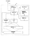
図6は生物スキャナ10の内部動作を図示するブロック図である。図6に図示するように、生物成長プレート22は台(図6では図示せず)上の生物スキャナ10の内部に配置されている。台は生物成長プレート22を撮像装置32の所望の焦点面に配置する。撮像装置32は成長プレート22の上面および背面照明用の照明ハードウェア、および成長プレート22の表面の画像を取り込むラインまたはエリアスキャナを含み得る。撮像装置32が標準画像取込条件を適用するか、またはユーザが画像取込条件を指定し得る。代替的には以下に説明するようにスキャナ10は、プレートタイプに対応する画像処理プロファイルに基づいて自動的に画像取込条件を制御し得る。
FIG. 6 is a block diagram illustrating the internal operation of the
いくつかの実施形態において、例えば撮像装置32は二次元カメラの形状を取り得るが、ラインスキャナはカメラまたは生物成長プレート22のいずれかが他に対して並進される構成で使用できる。一般に撮像装置32は生物成長プレート22または少なくとも生物成長プレート内の成長領域の画像を取り込む。プロセッサ34は撮像装置32の動作を制御する。動作中、プロセッサ34は撮像装置32を制御して生物成長プレート22の画像を取り込む。プロセッサ34は撮像装置32から走査画像を表わす画像データを受け取るとともに、画像の一部分を抽出または分離してプレートタイプ標識28を隔離する。
In some embodiments, for example, the
プロセッサ34はマシンビジョン技術を利用してプレートタイプ標識28を分析し、生物成長プレート22に関連するプレートタイプを識別する。そしてプロセッサ34は画像処理プロファイルメモリ36から画像処理プロファイルを検索する。画像処理プロファイルは検出されたプレートタイプに対応している。プロセッサ34はマイクロプロセッサ、デジタル信号プロセッサ、アプリケーション特定用途向け集積回路(ASIC)、フィールド・プログラマブル・ゲート・アレイ(FPGA)または本明細書に記載されているような機能性を提供するようにプログラムまたは構成された他の集積または個別論理回路の形状を取り得る。
The
プロセッサ34は画像処理プロファイルを利用して適正な画像分析パラメータを読み込むとともに生物成長プレート22の走査画像を処理するように進行する。このようにプロセッサ34は生物成長プレート22から得られた画像データを処理するという意味で画像処理装置をなす。画像分析パラメータは画像処理プロファイルおよび検出されたプレートタイプとともに変化して、走査画像の分析に対してコロニーの色、サイズ、形状および近接基準などの特定のパラメータを指定し得る。
The
いくつかのプレートタイプの場合、例えば周囲の栄養培地の色は高コロニー数の標識であり得る。また特定の炭水化物およびpH指示薬を含むプレートの場合、色は有機体のタイプの標識になり得る。気泡などの隣接物体も有機体のタイプの標識になり得る。従って様々な画像処理基準および関連するパラメータを様々なプレートタイプに対して指定し得る。基準は被分析プレート22のタイプにより異なるとともに、生物スキャナ10により生成されるコロニー数または他の分析結果に大きく影響し得る。
For some plate types, for example, the color of the surrounding nutrient medium can be a high colony number label. Also, for plates containing certain carbohydrates and pH indicators, the color can be an organism type label. Adjacent objects, such as bubbles, can also be organic type labels. Accordingly, different image processing criteria and associated parameters can be specified for different plate types. Criteria vary depending on the type of
適切な画像処理パラメータを選択すると、プロセッサ34は走査画像を処理するとともに、ディスプレイ16を介してユーザに提示されるコロニー数などの分析結果を生成する。またプロセッサ34は後にスキャナ10から検策するために、分析結果をカウントデータメモリ38などのメモリに記憶する。カウントデータメモリ38に記憶されたデータは例えば通信ポート40、例えばユニバーサルシリアルバス(USB)ポートを介して生物スキャナ10と通信しているホストコンピュータによって検索し得る。ホストコンピュータは、分析のために生物スキャナ10に提示される一連の生物成長プレート22に対する分析結果をコンパイルし得る。
Upon selection of appropriate image processing parameters,
生物スキャナ10内の画像処理プロファイルの自動選択は、適当な画像処理プロファイルを選択するための便利で精度の高い技術を提供することができる。画像処理プロファイルの自動選択は細菌コロニー計数および他の分析手順の精度を向上させることができる。特に自動画像処理プロファイル選択により技術者がプレートタイプを目視で識別して手動で入力する必要性をなくすことができる。このようにして人間の介入に関連する場合もあるプレート識別エラーをなくすことができる。その結果、スキャナ10とプレートタイプ標識28を担持する生物成長プレート22とを組み合わせると、効率および実験技術者の作業フローを向上させることができる一方、分析精度、そして最終的には食品安全性および人間の健康を高めることができる。
Automatic selection of an image processing profile within the
図7は自動画像処理プロファイル選択のために構成された他の生物スキャナ10’を図示するブロック図である。生物スキャナ10’は図6の生物スキャナ10と実質的に一致するが、コード読取装置42をさらに含んでいる。生物成長プレート22の走査画像からプレートタイプ標識28を抽出する代わりに、コード読取装置42はプレートタイプ情報を得る専用の読取装置として機能する。例えばプレートタイプ標識28の形状によって、コード読取装置42は専用の光学読取装置、バーコード読取装置、磁気読取装置、無線または機械的読取装置の形状を取り得る。
FIG. 7 is a block diagram illustrating another biological scanner 10 'configured for automatic image processing profile selection.
いずれの場合もコード読取装置42はプレートタイプ標識28からプレートタイプを識別するとともにプレートタイプをプロセッサ34に伝達する働きをする。そしてプロセッサ34は識別したプレートタイプに基づいてメモリ36から画像処理プロファイルを選択する。撮像装置32は生物成長プレート22を走査して画像データをプロセッサ34に提供する。そしてプロセッサ34は検索した画像処理プロファイルにより指定された画像処理パラメータを適用して画像を処理するとともにコロニー数などの分析結果を生成する。このようにプロセッサ34は自動識別プレートタイプの点で自動的に適正な画像処理プロファイルを適用することにより、ユーザに対して向上した精度、効率および便利さを提供する。具体的にはこのような実施形態において本発明はユーザがプレートタイプ識別を手で入力する必要性をなくすとともに、人間の間違った入力による分析エラーの可能性を低減する。
In either case, the
図8は図6の生物スキャナ10をより詳細に図示するとともにプレート照明ハードウェアを示すブロック図である。図8に示すように生物スキャナ10は前面照明システム44と、背面照明システム46と、を含み得る。前面照明システム44は生物成長プレート22の前面側を照明し、背面照明システム46は生物成長プレートの背面側を照明する。前面および下面照明システム44および46は選択的に異なる照明強度、色および継続時間を生じ得る。具体的にはプロセッサ34は前面および下面照明システム44、46を制御して生物成長プレート22を異なる照明色に露光する。前面および背面照明システム44、46は照明源としてLEDを内蔵し得る。LEDはプロセッサ34および適当な駆動回路により容易に制御されて所望の照明強度と継続時間とを達成できる。
FIG. 8 is a block diagram illustrating the
さらにプロセッサ34はカメラ43を制御して異なる色での照明中に生物成長プレート22の画像を取り込み得る。例えばプロセッサ34は照明システム44、46およびカメラ43を協調制御して生物成長プレート22の1つ以上の画像を取り込む。カメラ43は前面照明システム44、背面照明システム46または両方による照明中に生物成長プレート22の1つ以上の画像を取り込むとともに、その画像を画像メモリ47に記憶し得る。場合によってプロセッサ34は画像処理プロファイルにより指定された画像取込条件に応じてカメラ利得、解像度、アパーチャ、露光時間等を制御し得る。
Further, the
プロセッサ34は記憶された画像を用いて画像処理プロファイルにより指定された画像分析基準に従って画像分析を行う。具体的にはプロセッサ34はその後個々の画像を分析するか、多数の画像を組み合わせて複合画像を形成する。いくつかの実施形態において例えばプロセッサ34は照明システム44、46を制御して、生物成長プレート22の赤色、緑色、および青色の画像を取り込むとともに、画像を個別にまたは複合多色画像として分析する。
The
生物成長プレート22のタイプによっては特定の色、強度および継続時間の照明を必要とする場合がある。さらに生物成長プレート22によっては両方ではなく前面または背面照明しか必要としない場合がある。例えば好気性細菌数プレートは前面照明のみ且つ赤色などの単一色のみによる照明を必要とする。また大腸菌/大腸菌型プレートは背面照明のみ且つ赤色と青色照明の組み合わせを必要とする。同様に異なるカメラ利得、解像度、アパーチャ、および露光時間はもとより、特定の強度レベルおよび継続時間が適正であり得る。これらの理由でプロセッサ34は画像処理プロファイルにより指定された画像取込条件に応じて照明およびカメラ条件を制御し得る。換言すればプレートタイプに基づく画像分析基準だけでなく画像を取り込むために適用される画像取込条件を選択するようにスキャナ10を構成することができる。
Some types of
照明の前にプレートタイプの識別を可能にするため、スキャナ10は図6および7に関して説明したものと同様な技術を適用し得る。図7に関して説明したように、例えば専用コード読取装置を設けて画像取込のための照明の前にプレートタイプを識別する。専用読取装置を用いてプレートタイプを識別すると、プロセッサ34は画像処理プロファイルメモリ36から対応する画像処理プロファイルを選択して、画像処理プロファイルにおいて指定された画像取込条件に従って照明を制御する。
To allow plate type identification prior to illumination,
代替的には図6に関して説明したようにマシンビジョン技術を適用して取込画像からプレートタイプを識別するようにスキャナ10を構成し得る。この場合プレートタイプ標識28を分析してプレートタイプ識別するため、スキャナ10は一組のデフォルト照明条件を適用して生物成長プレート22またはその一部の初期画像を取り込む。その後プロセッサ34は対応する画像処理プロファイルを選択するとともに、指定された画像取込条件を適用して生物成長の分析用画像を取り込む。
Alternatively, the
画像処理プロファイルを照明条件、画像分析基準またはその両方を指定するものとして本明細書に概説する。しかし個々のプロファイルを画像取込および画像分析に用いることもできる。例えばプレートタイプ識別に続いて、プロセッサ34は照明色、強度および継続時間などの画像取込条件を指定する画像取込プロファイルにアクセスし得る。その後取込画像の分析のため、プロセッサ34は色、形状、サイズおよび近接などの画像分析基準を指定する個々の画像分析プロファイルにアクセスし得る。
An image processing profile is outlined herein as specifying lighting conditions, image analysis criteria, or both. However, individual profiles can also be used for image capture and image analysis. For example, following plate type identification,
図6〜8の例はプレートタイプに基づく画像処理プロファイルの自動選択を示しているが、この選択はいくつかの実施形態において半自動になり得る。具体的にはプレートタイプ標識28によりプレートタイプを検出すると、プロセッサ34はディスプレイ16を介して事前プレートタイプ識別をユーザに提示し得る。さらにプロセッサ34は、対応画像処理プロファイルを用いて画像取込または分析が進行する前に自動的に識別されたプレートタイプをユーザが確認または拒絶することを可能にし得る。ユーザは例えばポインティングデバイスを作動させるかまたはタッチスクリーンの領域を押圧することにより事前プレートタイプ識別を確認または拒絶し得る。ユーザが自動検出プレートタイプ識別がエラーであると思う場合には、プロセッサ34はユーザがプレートタイプ識別を変更することを可能にし得る。
While the examples of FIGS. 6-8 illustrate automatic selection of an image processing profile based on plate type, this selection can be semi-automatic in some embodiments. Specifically, upon detection of a plate type by the
図9はプレートタイプ検出時に生物スキャナ10によりディスプレイ16上に生成されるサンプル表示内容である。図9に示すように、ディスプレイ16は事前プレートタイプ識別、すなわちプロセッサ34により自動的に作成されたプレートタイプ識別を提示する。図9の例において、ディスプレイ16は「プレートタイプ=リステリア」を示している。さらにディスプレイ16は、それぞれユーザ入力を受け付けて事前プレートタイプ識別がユーザにより確認されたか拒絶されたかを示す2つのタッチスクリーン領域52、54を提示する。
FIG. 9 shows sample display contents generated on the
図10はユーザによる自動プレートタイプ検出の拒絶時に生物スキャナ10のディスプレイ16により生成されるサンプル表示内容である。例えば図9に示すようにユーザが事前プレートタイプ識別を拒絶した場合、プロセッサ34はディスプレイ16を駆動して「プレートタイプを入力する」のダイアログを提示し、それによりユーザは図10に示すように正しいプレートタイプ識別を選択し得る。ディスプレイ16は、ユーザが代替プレートタイプ識別を例えば適当なタッチスクリーン領域を押下することにより選択できるようにする垂直スクロールバーメニュー56を提示し得る。代替プレートタイプ識別を選択すると、プロセッサ34は例えば画像取込条件、画像分析基準または両方を含む代替画像処理プロファイルを選択し得る。
FIG. 10 shows sample display contents generated by the
図11はコロニー数の判定時に生物スキャナ10のディスプレイ16により生成されるサンプル内容である。図11に示すように、プロセッサ34はディスプレイ16を駆動して「プレート走査完了」メッセージを提示するとともにプレートタイプを識別し得る(「プレートタイプ=リステリア」)。さらに生物成長プレート22の分析が完了すると、プロセッサ34はディスプレイ16を駆動して計数58(「計数=XX」)を提示する。ディスプレイ16は他のタイプの分析結果も提示し得る。
FIG. 11 shows sample contents generated by the
図12はコロニー数の判定時に生物スキャナ10のディスプレイ16により生成されるサンプル内容であり走査されたプレートの画像を含む。図12の例においてディスプレイ16は図11に示したものと同様の情報を提示するが、生物成長プレート22の表面から生物スキャナ10によって走査された実際の画像の表示60をさらに含む。このようにユーザは計数58などの分析結果と走査画像の表示60との両方を見ることができる。いくつかの実施形態において画像表示60は十分な量の詳細を提示するためユーザは自動判定計数を確かめることができる。他の実施形態において画像表示60は低解像表示であり得る。
FIG. 12 shows sample contents generated by the
図13は生物スキャナ10における画像処理プロファイル選択のためのプロセスを図示するフロー図である。図13に示すように、このプロセスはスキャナ10に提示される生物成長プレート22に対してプレートタイプを識別するステップ(62)を含み得る。このプロセスはプレート画像を走査する(66)前または後いずれかに、プレートタイプに基づく画像処理プロファイルの選択(64)をさらに含み得る。画像処理プロファイルが画像取込条件を指定する場合には、照明条件、カメラ性能またはその両方を制御できるように画像処理プロファイルをプレート画像の走査前に選択しなければならない。プロセスは選択した画像処理プロファイルにより指定された画像分析基準を用いて、プレート画像を処理して分析結果を生成するステップ(68)をさらに含む。具体的にはプロセスは細菌コロニー数を生成(70)し得る。図13の例において、プレートタイプはプレート画像を走査する前に識別される。
FIG. 13 is a flow diagram illustrating a process for image processing profile selection in the
図14はプレートタイプ標識の検出を含む、生物スキャナにおける画像処理プロファイル選択のためのプロセスを図示するフロー図である。図14に示すようにこのプロセスは生物成長プレートにより担持されているプレートタイプ標識を、たとえば光学読取装置、バーコード読取装置、磁気読取装置、無線読取装置、機械的読取装置等などの専用のプレートタイプ標識読取装置で読み取るステップ(72)を含む。プレートタイプ標識に基づいてプレートタイプを判定すると(74)、プロセスは検出されたプレートタイプに基づいて画像処理プロファイルを選択するステップ(76)を含む。さらにプロセスは生物成長プレートの画像を走査するステップ(78)と、選択した画像処理プロファイルによって指定されたパラメータに従ってプレート画像を処理するステップ(80)と、を含む。プロセスはその後コロニー数などの分析結果を生成する(81)。 FIG. 14 is a flow diagram illustrating a process for image processing profile selection in a biological scanner, including detection of plate type labels. As shown in FIG. 14, this process uses a plate type indicator carried by a biological growth plate, such as a dedicated plate such as an optical reader, bar code reader, magnetic reader, wireless reader, mechanical reader, etc. Reading with a type indicator reader (72). Once the plate type is determined based on the plate type indicator (74), the process includes selecting an image processing profile based on the detected plate type (76). The process further includes scanning (78) an image of the biological growth plate and processing (80) the plate image according to the parameters specified by the selected image processing profile. The process then generates an analysis result such as the number of colonies (81).
図15は走査されたプレート画像からのプレートタイプ標識の抽出を含む、生物スキャナにおける画像処理プロファイル選択のためのプロセスを図示するフロー図である。図15に示すように、プロセスは生物成長プレートの画像を走査するステップ(82)と、走査画像からプレートタイプ標識エリアを抽出するステップ(84)と、を含む。プロセスは抽出したプレートタイプ標識エリアを処理して(86)、プレートタイプを判定するステップ(88)をさらに含む。プレートタイプ標識に基づいてプレートタイプを判定する(88)と、プロセスは検出されたプレートタイプに基づいて画像処理プロファイルを選択するステップ(90)を含む。その後プロセスはプレートを例えば選択した画像処理プロファイルにより指定された画像取込条件を用いて再度走査するステップ(91)と、選択した画像処理プロファイルにより指定された画像分析基準に従ってプレート画像を処理するステップ(92)と、を含む。その後プロセスはコロニー数などの分析結果を生成する(94)。 FIG. 15 is a flow diagram illustrating a process for image processing profile selection in a biological scanner, including extraction of plate type indicators from scanned plate images. As shown in FIG. 15, the process includes scanning (82) an image of the biological growth plate and extracting (84) a plate type indicator area from the scanned image. The process further includes processing (86) the extracted plate type indicator area to determine a plate type (88). Once the plate type is determined (88) based on the plate type indicator, the process includes selecting (90) an image processing profile based on the detected plate type. The process then scans the plate again, for example using the image capture conditions specified by the selected image processing profile (91), and processes the plate image according to the image analysis criteria specified by the selected image processing profile. (92). The process then generates an analysis result such as the number of colonies (94).
図16はユーザが生物スキャナによる自動プレートタイプ識別を無効にできるようにするプロセスを図示するフロー図である。図16に示すように、プロセスは生物成長プレート22に関連するプレートタイプを自動的に判定するステップ(96)と、判定したプレートタイプをディスプレイ16を介してユーザに提示するステップ(98)と、を含む。プロセスは自動的に判定したプレートタイプを受容または拒絶するユーザ入力を、例えばタッチスクリーン入力を介して受け付けるステップ(100)をさらに含む。プレートタイプがユーザに受容されない場合には、プロセスはユーザ入力を受け付けユーザからプレートタイプを受け取るステップ(102)を含む。ユーザがプレートタイプを入力する(102)かまたは自動判定プレートタイプを受容する(100)と、プロセスはプレートタイプに基づく画像処理プロファイルの選択(104)を含む。選択した画像処理プロファイルを用いて、プロセスはプレート画像を走査し(105)、プレート画像を処理し(106)、さらにコロニー数または他の所望分析結果を生成する(108)。
FIG. 16 is a flow diagram illustrating a process that allows a user to override automatic plate type identification by a biological scanner. As shown in FIG. 16, the process automatically determines (96) the plate type associated with the
動作中、プロセッサ34はコンピュータ読取可能媒体に記憶され得る命令を実行して、本明細書に記載されたプロセスを行う。コンピュータ読取可能媒体は、同時性ダイナミックランダムアクセスメモリ(SDRAM)などのランダムアクセスメモリ(RAM)、読み出し専用メモリ(ROM)、不揮発性ランダムアクセスメモリ(NVRAM)、電気的消去可能プログラム可能読み出し専用メモリ(EEPROM)、フラッシュ(FLASH)メモリ、磁気または光学データ記憶媒体等を含み得る。
In operation,
本発明の精神と範囲とから逸脱することなく様々な変更を行うことができる。これらおよび他の実施形態は以下の請求の範囲の範囲内にあるものである Various changes can be made without departing from the spirit and scope of the invention. These and other embodiments are within the scope of the following claims.
Claims (33)
生物成長プレートに関連するプレートタイプに基づいて前記画像処理プロファイルのうちの1つを選択する画像処理装置と、
を含む装置。 Means for storing a set of image processing profiles;
An image processing device for selecting one of the image processing profiles based on a plate type associated with the biological growth plate;
Including the device.
前記検出したプレートタイプに基づいて複数の画像処理プロファイルのうちの1つを選択するステップと、
前記選択した画像処理プロファイルに従って前記生物成長プレートの画像を処理するステップと、
を含む方法。 Detecting a plate type associated with the biological growth plate;
Selecting one of a plurality of image processing profiles based on the detected plate type;
Processing an image of the biological growth plate according to the selected image processing profile;
Including methods.
前記生物成長プレートのタイプを識別する機械可読プレートタイプ標識と、
を含む生物成長プレート。 A plate surface that supports the growth of biological agents;
A machine readable plate type indicator identifying the type of the biological growth plate;
Including biological growth plate.
前記生物成長プレートの画像を取り込むとともに、前記プレートタイプ標識に基づいて選択された複数の画像処理プロファイルのうちの1つに従って前記画像を処理する撮像装置と、
を含むシステム。 A biological growth plate according to claim 20;
An imaging device that captures an image of the biological growth plate and processes the image according to one of a plurality of image processing profiles selected based on the plate type indicator;
Including system.
23. The method of claim 16, the biological growth plate of claim 20, or the system of claim 21 wherein the plate type is associated with a thin film culture plate.
Applications Claiming Priority (2)
| Application Number | Priority Date | Filing Date | Title |
|---|---|---|---|
| US10/306,579 US7298885B2 (en) | 2002-11-27 | 2002-11-27 | Biological growth plate scanner with automated image processing profile selection |
| PCT/US2003/037386 WO2004051554A1 (en) | 2002-11-27 | 2003-11-21 | Biological growth plate scanner with automated image processing profile selection |
Related Child Applications (1)
| Application Number | Title | Priority Date | Filing Date |
|---|---|---|---|
| JP2010156333A Division JP5194068B2 (en) | 2002-11-27 | 2010-07-09 | Biological growth plate scanner with automatic image processing profile selection |
Publications (2)
| Publication Number | Publication Date |
|---|---|
| JP2006507837A true JP2006507837A (en) | 2006-03-09 |
| JP2006507837A5 JP2006507837A5 (en) | 2006-11-24 |
Family
ID=32325729
Family Applications (2)
| Application Number | Title | Priority Date | Filing Date |
|---|---|---|---|
| JP2004557258A Pending JP2006507837A (en) | 2002-11-27 | 2003-11-21 | Biological growth plate scanner with automatic image processing profile selection |
| JP2010156333A Expired - Fee Related JP5194068B2 (en) | 2002-11-27 | 2010-07-09 | Biological growth plate scanner with automatic image processing profile selection |
Family Applications After (1)
| Application Number | Title | Priority Date | Filing Date |
|---|---|---|---|
| JP2010156333A Expired - Fee Related JP5194068B2 (en) | 2002-11-27 | 2010-07-09 | Biological growth plate scanner with automatic image processing profile selection |
Country Status (11)
| Country | Link |
|---|---|
| US (3) | US7298885B2 (en) |
| EP (2) | EP2325778A1 (en) |
| JP (2) | JP2006507837A (en) |
| KR (1) | KR101120829B1 (en) |
| CN (2) | CN100342389C (en) |
| AT (1) | ATE527618T1 (en) |
| AU (1) | AU2003295804B2 (en) |
| BR (1) | BR0316406A (en) |
| CA (1) | CA2504616A1 (en) |
| MX (1) | MXPA05005378A (en) |
| WO (1) | WO2004051554A1 (en) |
Cited By (10)
| Publication number | Priority date | Publication date | Assignee | Title |
|---|---|---|---|---|
| JP2011512845A (en) * | 2008-03-04 | 2011-04-28 | スリーエム イノベイティブ プロパティズ カンパニー | Treatment of biological growth media based on measured manufacturing characteristics |
| JP2012075409A (en) * | 2010-10-04 | 2012-04-19 | Microbio Corp | Colony detection method, colony detection system and colony detection program |
| JP2014124116A (en) * | 2012-12-25 | 2014-07-07 | Dainippon Printing Co Ltd | Medium information registration system and program, and sanitation management system |
| JP2015073466A (en) * | 2013-10-08 | 2015-04-20 | 大日本印刷株式会社 | Culture medium information registration system and colony detection system |
| JP2015536140A (en) * | 2012-11-07 | 2015-12-21 | バイオメリュー | Bioimaging method |
| JP2016508034A (en) * | 2012-12-20 | 2016-03-17 | スリーエム イノベイティブ プロパティズ カンパニー | Method for distinguishing microbial colonies in images |
| JP2016510211A (en) * | 2012-12-20 | 2016-04-07 | スリーエム イノベイティブ プロパティズ カンパニー | Method for detecting colonies of gas-producing microorganisms |
| JP2016158577A (en) * | 2015-03-03 | 2016-09-05 | 富士フイルム株式会社 | Cell colony detection device, cell colony detection method, and program |
| WO2018061131A1 (en) * | 2016-09-28 | 2018-04-05 | オリンパス株式会社 | Cell status assessment device |
| JP2019080578A (en) * | 2019-02-27 | 2019-05-30 | 富士フイルム株式会社 | Cell colony detection device, cell colony detection method, and program |
Families Citing this family (51)
| Publication number | Priority date | Publication date | Assignee | Title |
|---|---|---|---|---|
| US7351574B2 (en) * | 2002-11-27 | 2008-04-01 | 3M Innovative Properties Company | Loading and ejection systems for biological growth plate scanner |
| US20040102903A1 (en) * | 2002-11-27 | 2004-05-27 | Graessle Josef A. | Biological growth plate scanner |
| US7298885B2 (en) | 2002-11-27 | 2007-11-20 | 3M Innovative Properties Company | Biological growth plate scanner with automated image processing profile selection |
| US7319031B2 (en) * | 2002-11-27 | 2008-01-15 | 3M Innovative Properties Company | Mounting platform for biological growth plate scanner |
| US20040101954A1 (en) | 2002-11-27 | 2004-05-27 | Graessle Josef A. | Back side plate illumination for biological growth plate scanner |
| US7496225B2 (en) * | 2003-09-04 | 2009-02-24 | 3M Innovative Properties Company | Biological growth plate scanner with automated intake |
| US7298886B2 (en) * | 2003-09-05 | 2007-11-20 | 3M Innovative Properties Company | Counting biological agents on biological growth plates |
| US20080238627A1 (en) * | 2005-03-22 | 2008-10-02 | Applera Corporation | Sample carrier device incorporating radio frequency identification, and method |
| US7187286B2 (en) | 2004-03-19 | 2007-03-06 | Applera Corporation | Methods and systems for using RFID in biological field |
| JP4713261B2 (en) * | 2005-07-20 | 2011-06-29 | 株式会社カネカ | Cell culture equipment |
| JP4821279B2 (en) * | 2005-11-11 | 2011-11-24 | 株式会社ニコン | Incubator |
| EP1882948A2 (en) * | 2006-07-28 | 2008-01-30 | Qiagen GmbH | Sample processing device |
| BRPI0812626B1 (en) * | 2007-07-09 | 2018-01-23 | 3M Innovative Properties Company | MODULAR SYSTEM |
| WO2009108229A2 (en) | 2007-11-20 | 2009-09-03 | 3M Innovative Properties Company | Environmental sampling articles and methods |
| JP5420566B2 (en) | 2007-12-21 | 2014-02-19 | スリーエム イノベイティブ プロパティズ カンパニー | Microbial system and fluid sample analysis method |
| US8417013B2 (en) * | 2008-03-04 | 2013-04-09 | 3M Innovative Properties Company | Information management in automated processing of biological growth media |
| US8005775B2 (en) * | 2008-03-18 | 2011-08-23 | Yahoo! Inc. | System and method for detecting human judgment drift and variation control |
| ES2434964T3 (en) * | 2008-03-26 | 2013-12-18 | 3M Innovative Properties Company | Spectral analysis of biological growth media |
| EP2347007A2 (en) * | 2008-10-17 | 2011-07-27 | 3M Innovative Properties Company | Biological sterilization indicator, system, and methods of using same |
| JP5480559B2 (en) * | 2008-10-30 | 2014-04-23 | シスメックス株式会社 | Bacteria analyzer, bacteria analysis method, and computer program |
| EP2199956A1 (en) * | 2008-12-18 | 2010-06-23 | Siemens Aktiengesellschaft | Method and system for managing results of an analysis process on objects handled along a technical process line |
| WO2010078284A1 (en) | 2008-12-31 | 2010-07-08 | 3M Innovative Properties Company | Coliform detection process and kit for use therein |
| WO2011055791A1 (en) * | 2009-11-05 | 2011-05-12 | 株式会社日立ハイテクノロジーズ | Device for harvesting bacterial colony and method therefor |
| CN102713617B (en) | 2009-12-30 | 2015-11-25 | 3M创新有限公司 | Produce the rapid detection of the mould of glucose oxidase |
| US8753834B2 (en) | 2009-12-30 | 2014-06-17 | 3M Innovative Properties Company | Microbial detection article |
| JP5707399B2 (en) * | 2010-06-23 | 2015-04-30 | 株式会社エヌテック | Microorganism detection method, microorganism detection apparatus, and program |
| FR2964215B1 (en) * | 2010-08-25 | 2013-06-14 | Intelligence Artificielle Applic | USE OF A DATAMATRIX CODE AND PRINTING METHOD |
| CN102024259B (en) * | 2010-12-24 | 2012-06-20 | 刘安安 | Bacterial colony automatic detection method |
| JP5849976B2 (en) * | 2012-03-30 | 2016-02-03 | カシオ計算機株式会社 | Social network service system and image display method |
| JP5998744B2 (en) * | 2012-08-23 | 2016-09-28 | 大日本印刷株式会社 | Colony detection device, medium information registration system, hygiene management system, and program |
| JP2014135949A (en) * | 2013-01-18 | 2014-07-28 | Dainippon Printing Co Ltd | Culture medium information registration system, culture medium image analysis device, program, and health management system |
| JP2014135948A (en) * | 2013-01-18 | 2014-07-28 | Dainippon Printing Co Ltd | Culture medium information registration system, colony detection device, program, and health management system |
| JP2014140335A (en) * | 2013-01-24 | 2014-08-07 | Dainippon Printing Co Ltd | Medium image analyzing device, medium information registration system and program, and hygiene management system |
| US8921067B2 (en) | 2013-02-04 | 2014-12-30 | 3M Innovative Properties Company | Method and culture device for detecting yeasts and molds |
| CN106103689A (en) | 2014-03-07 | 2016-11-09 | 3M创新有限公司 | For detecting goods and the method for aerobic bacteria |
| US10407654B1 (en) | 2014-03-21 | 2019-09-10 | Charm Sciences, Inc. | Growth plate devices, kits and assemblies |
| JP5904295B2 (en) * | 2014-03-31 | 2016-04-13 | 大日本印刷株式会社 | Colony detection system, colony detection method, and program |
| US10563164B1 (en) * | 2015-10-08 | 2020-02-18 | Charm Sciences, Inc. | Plate reader |
| US10988720B1 (en) | 2015-11-09 | 2021-04-27 | Charm Sciences, Inc. | Peel plate assembly |
| CN108350409B (en) * | 2015-12-28 | 2022-06-14 | 日本理化学开发公司 | Viable/dead bacteria state determination device and viable/dead bacteria state determination method using same |
| US10495563B1 (en) | 2016-04-28 | 2019-12-03 | Charm Sciences, Inc. | Plate reader observation methods and operation |
| WO2018056134A1 (en) * | 2016-09-20 | 2018-03-29 | 日本水産株式会社 | Method for producing fish roe paste having foreign substances removed therefrom, and apparatus for producing fish roe paste having foreign substances removed therefrom |
| CA3042681A1 (en) * | 2016-11-04 | 2018-05-11 | Becton, Dickinson And Company | System and method for selecting colonies |
| WO2018089681A1 (en) * | 2016-11-10 | 2018-05-17 | Becton, Dickinson And Company | Timeline system for monitoring a culture media protocol |
| CN107644210B (en) * | 2017-09-22 | 2020-05-12 | 哈尔滨工业大学(威海) | Image processing-based microorganism quantity estimation method |
| CN108251270B (en) * | 2018-01-16 | 2022-11-15 | 上海睿度光电科技有限公司 | Equipment for covering cells with quantitative solution |
| SG11202007070VA (en) | 2018-01-30 | 2020-08-28 | Life Technologies Corp | Instruments, devices and consumables for use in a workflow of a smart molecular analysis system |
| FR3080211B1 (en) | 2018-04-16 | 2020-05-08 | Pinqkerton | SYSTEM AND METHOD FOR ANALYZING TEST DEVICES |
| KR102043670B1 (en) * | 2018-04-27 | 2019-11-12 | 이상인 | Automatic microorganism management incubator system |
| CN109975290A (en) * | 2018-11-30 | 2019-07-05 | 军事科学院军事医学研究院环境医学与作业医学研究所 | A kind of Bacteria Detection quick analytic instrument |
| JP7259732B2 (en) * | 2019-12-23 | 2023-04-18 | 横河電機株式会社 | Distribution server, method and program |
Family Cites Families (113)
| Publication number | Priority date | Publication date | Assignee | Title |
|---|---|---|---|---|
| US3493772A (en) | 1967-05-29 | 1970-02-03 | Palo Alto Medical Research Fou | Bacterial counting machine and method |
| US3745090A (en) * | 1970-08-04 | 1973-07-10 | Nasa | Method of detecting and counting bacteria in body fluids |
| US3811036A (en) | 1972-09-19 | 1974-05-14 | Artek Syst Corp | Micro-biological colony counter |
| US3962040A (en) | 1974-03-14 | 1976-06-08 | The United States Of America As Represented By The Department Of Health, Education And Welfare | Method and apparatus for plating and counting aerobic bacteria |
| US4118280A (en) | 1976-05-03 | 1978-10-03 | Mcdonnell Douglas Corporation | Automated microbial analyzer |
| US4146775A (en) * | 1976-09-16 | 1979-03-27 | Armstrong Machine Works | Automatic control system for an electrode-type air humidifier |
| US4160601A (en) | 1978-02-24 | 1979-07-10 | Nasa | Biocontamination and particulate detection system |
| DK366778A (en) | 1978-08-18 | 1980-02-19 | Foss Electric As | METHOD OF COUNTING BACTERIES |
| GB2090972B (en) * | 1980-05-09 | 1985-06-19 | Unilever Plc | Apparatus for assisting the visual assessment of test objects having multivariate visible characteristics and its use |
| US4353988A (en) | 1980-11-12 | 1982-10-12 | Couse Nancy L | Grid for use in counting colonies of bacteria present in discrete areas of a spiral deposition pattern |
| US4424191A (en) | 1982-03-04 | 1984-01-03 | Eastman Kodak Company | Analyzer featuring loading and unloading means for a storage chamber, and common drive means |
| US4591567A (en) | 1982-04-21 | 1986-05-27 | California Institute Of Technology | Recombinant DNA screening system including fixed array replicator and support |
| JPS6083597A (en) | 1983-10-10 | 1985-05-11 | Hitachi Electronics Eng Co Ltd | Method for testing colony |
| US4637053A (en) | 1984-05-03 | 1987-01-13 | Spiral System Instruments, Inc. | Computer assisted biological assay system |
| US4720463A (en) | 1985-03-01 | 1988-01-19 | Sherwood Medical Company | Automated microbiological testing apparatus |
| DE3686067T2 (en) | 1985-02-27 | 1993-03-18 | Sherwood Medical Co | METHOD AND DEVICE FOR AUTOMATIC MICROBIOLOGICAL ANALYSIS. |
| US4724215A (en) | 1985-02-27 | 1988-02-09 | Sherwood Medical Company | Automated microbiological testing apparatus and method |
| JPS62215383A (en) | 1986-03-17 | 1987-09-22 | Datsuku Eng Kk | Apparatus for inspecting microscopic life |
| JPS6435347A (en) | 1987-07-31 | 1989-02-06 | Sumitomo Electric Industries | Detection of intrusion of various bacteria |
| US5270173A (en) * | 1987-10-06 | 1993-12-14 | Sumitomo Electric Industries, Ltd. | Method of monitoring cell culture |
| US5202010A (en) * | 1987-11-25 | 1993-04-13 | Princeton Biochemicals, Inc. | Automated capillary electrophoresis apparatus |
| JPH01296974A (en) | 1988-05-23 | 1989-11-30 | Toyo Jozo Co Ltd | Colony counter |
| CA2014647C (en) | 1989-05-09 | 1994-09-20 | James David Shaw | Analyzer featuring a circular track of cartridges centered on an incubator, and method of use |
| US5266486A (en) * | 1989-05-12 | 1993-11-30 | Nvl Photronics Corporation | Method and apparatus for detecting biological activities in a specimen |
| WO1991006911A1 (en) * | 1989-10-23 | 1991-05-16 | Neuromedical Systems, Inc. | Automated cytological specimen classification system and method |
| DE3938565A1 (en) | 1989-11-21 | 1991-05-23 | Behringwerke Ag | INCUBATIONAL DEVICE FOR MICROTITRATION PLATES |
| GB2249829A (en) | 1990-11-13 | 1992-05-20 | Powergen Public Limited Compan | Measurement of carbon in ash |
| GB9100623D0 (en) | 1991-01-11 | 1991-02-27 | Medical Res Council | Transfer of biological samples |
| US5290701A (en) | 1991-08-28 | 1994-03-01 | Wilkins Judd R | Microbial detection system and process |
| US5428690A (en) | 1991-09-23 | 1995-06-27 | Becton Dickinson And Company | Method and apparatus for automated assay of biological specimens |
| US5448652A (en) | 1991-09-27 | 1995-09-05 | E. I. Du Pont De Nemours And Company | Adaptive display system |
| US5481620A (en) | 1991-09-27 | 1996-01-02 | E. I. Du Pont De Nemours And Company | Adaptive vision system |
| US6058209A (en) * | 1991-09-27 | 2000-05-02 | E. I. Du Pont De Nemours And Company | Method for resolving redundant identifications of an object |
| US5329686A (en) | 1991-12-19 | 1994-07-19 | Eastman Kodak Company | Slide frame and manufacturing process |
| JPH0698220A (en) | 1992-05-29 | 1994-04-08 | Hooya Shiyotsuto Kk | Video camera |
| US5366873A (en) | 1992-06-03 | 1994-11-22 | Gideon Eden | Device and method for use in detecting microorganisms in a sample |
| WO1994001528A1 (en) | 1992-07-13 | 1994-01-20 | Minnesota Mining And Manufacturing Company | A technique to count objects in a scanned image |
| JPH0651129A (en) | 1992-07-27 | 1994-02-25 | Inoue Denki Kk | Illuminating device |
| US5591974A (en) * | 1992-09-30 | 1997-01-07 | Westinghouse Electric Corporation | Automated collection and processing of environmental samples |
| JP2777509B2 (en) | 1992-09-30 | 1998-07-16 | 出光石油化学株式会社 | Color inspection method |
| DE4238550A1 (en) | 1992-11-14 | 1994-05-19 | Daimler Benz Ag | Exhaust gas turbocharger for an internal combustion engine |
| WO1994026870A1 (en) | 1993-05-14 | 1994-11-24 | Minnesota Mining And Manufacturing Company | Method for rapid quantification of microorganism growth |
| US5364766A (en) | 1993-05-14 | 1994-11-15 | Minnesota Mining And Manufacturing Company | Culture medium for rapid count of coliform bacteria |
| US5723308A (en) | 1993-05-14 | 1998-03-03 | Minnesota Mining And Manufacturing Company | Culture medium for rapid count of coliform bacteria |
| EP0767361B1 (en) | 1993-07-22 | 2000-02-23 | Applied Spectral Imaging Ltd. | Method and apparatus for spectral imaging |
| US5995645A (en) | 1993-08-18 | 1999-11-30 | Applied Spectral Imaging Ltd. | Method of cancer cell detection |
| DE69417578T2 (en) | 1993-12-17 | 1999-08-12 | Minnesota Mining & Mfg | AUTOMATIC INCUBATION AND IMAGING DEVICE FOR DISPOSABLE CULTIVATION MEDIA FOR MICRO-ORGANISMS |
| JPH07275200A (en) | 1994-04-15 | 1995-10-24 | Asahi Optical Co Ltd | Illuminator for endoscope |
| US5573950A (en) | 1994-05-11 | 1996-11-12 | Minnesota Mining And Manufacturing Company | Cassette for disposable microorganism culturing media and automated scanning system |
| JPH08116408A (en) | 1994-08-24 | 1996-05-07 | Nikon Corp | Panel light source and image reader |
| EP0791205A4 (en) * | 1994-09-20 | 1999-04-21 | Neopath Inc | Biological analysis system self-calibration apparatus |
| US5694478A (en) | 1994-12-15 | 1997-12-02 | Minnesota Mining And Manufacturing Company | Method and apparatus for detecting and identifying microbial colonies |
| US6319668B1 (en) * | 1995-04-25 | 2001-11-20 | Discovery Partners International | Method for tagging and screening molecules |
| US6151405A (en) * | 1996-11-27 | 2000-11-21 | Chromavision Medical Systems, Inc. | System and method for cellular specimen grading |
| US5721435A (en) | 1996-04-09 | 1998-02-24 | Hewlett Packard Company | Methods and apparatus for measuring optical properties of biological and chemical substances |
| JP3777661B2 (en) * | 1996-07-10 | 2006-05-24 | 株式会社明電舎 | Filtration disorder microorganism monitoring device |
| DE19629141A1 (en) | 1996-07-19 | 1998-04-16 | Bayer Ag | Method and device for screening molecules for their individual binding behavior to at least one predetermined ligand |
| US6381353B1 (en) | 1996-08-30 | 2002-04-30 | Marvin Weiss | System for counting colonies of micro-organisms in petri dishes and other culture media |
| DE29618623U1 (en) | 1996-10-25 | 1997-02-06 | Jencons Scient Ltd | Device for cultivating microorganisms |
| US5817475A (en) | 1996-11-15 | 1998-10-06 | Giles Scientific, Inc. | Automatic microbiological testing apparatus and method |
| GB9624927D0 (en) * | 1996-11-29 | 1997-01-15 | Oxford Glycosciences Uk Ltd | Gels and their use |
| EP0983499B1 (en) | 1997-05-23 | 2005-10-26 | Becton, Dickinson and Company | Automated microbiological testing apparatus and methods therefor |
| US6002789A (en) | 1997-06-24 | 1999-12-14 | Pilot Industries, Inc. | Bacteria colony counter and classifier |
| US5911000A (en) * | 1997-08-01 | 1999-06-08 | Ortho Diagnostic Systems, Inc. | Detecting abnormal reactions in a red blood cell agglutination |
| KR100269125B1 (en) * | 1997-10-25 | 2000-10-16 | 윤덕용 | Image post processing method and apparatus for reducing quantization effect |
| ES2137879B1 (en) | 1997-12-02 | 2000-08-16 | Francisco Soria Melguizo S A | ANALYZING SYSTEM OF IMAGES PRODUCED BY BACTERIAL REACTIONS. |
| US6178205B1 (en) * | 1997-12-12 | 2001-01-23 | Vtel Corporation | Video postfiltering with motion-compensated temporal filtering and/or spatial-adaptive filtering |
| DE19819144C1 (en) | 1998-04-29 | 2000-06-15 | Tga Tech Geraete Und Apparateb | Microscopic investigation of implant integration into living tissues is carried out by automatically-scanning confocal laser microscope, digitizing image plane data to assemble three dimensional display |
| GB9811656D0 (en) * | 1998-05-29 | 1998-07-29 | Oxford Glycosciences Uk Ltd | Gels, methods and apparatus for identification and characterization of biomolecules |
| US6271042B1 (en) | 1998-08-26 | 2001-08-07 | Alpha Innotech Corporation | Biochip detection system |
| FR2786498B1 (en) | 1998-11-27 | 2002-02-08 | Intelligence Artificielle Appl | APPARATUS FOR AUTOMATICALLY READING AN ANTIBIOGRAM |
| US6107054A (en) | 1998-12-31 | 2000-08-22 | Gibbs; David | Microbiological testing apparatus and method |
| FR2789693B1 (en) | 1999-02-16 | 2001-05-25 | Intelligence Artificielle Appl | AUTOMATIC READING APPARATUS FOR A PETRI BOX PROVIDED WITH A LID |
| FR2789694B1 (en) | 1999-02-16 | 2003-05-16 | Intelligence Artificielle Appl | IMPROVEMENT FOR AN AUTOMATIC ANTIBIOGRAM READING APPARATUS |
| US6215894B1 (en) | 1999-02-26 | 2001-04-10 | General Scanning, Incorporated | Automatic imaging and analysis of microarray biochips |
| US6271022B1 (en) | 1999-03-12 | 2001-08-07 | Biolog, Inc. | Device for incubating and monitoring multiwell assays |
| US6251624B1 (en) * | 1999-03-12 | 2001-06-26 | Akzo Nobel N.V. | Apparatus and method for detecting, quantifying and characterizing microorganisms |
| JP2000270840A (en) * | 1999-03-29 | 2000-10-03 | Elmex Ltd | Colony counting system and usage thereof |
| US6534266B1 (en) | 1999-04-22 | 2003-03-18 | Albert Einstein College Of Medicine Of Yeshiva University | Assay of transcription sites by multi-fluor fish |
| EP1177448A2 (en) * | 1999-04-29 | 2002-02-06 | Dade MicroScan Inc. | A combined rapid anti-microbial susceptibility assay and microorganism identification system |
| US6731818B1 (en) * | 1999-06-30 | 2004-05-04 | Realnetworks, Inc. | System and method for generating video frames |
| WO2001004828A1 (en) | 1999-07-13 | 2001-01-18 | Chromavision Medical Systems, Inc. | Automated detection of objects in a biological sample |
| US6488890B1 (en) * | 1999-08-05 | 2002-12-03 | 3M Innovative Properties Company | Machine readable sterilization indicator for monitoring articles to be sterilized |
| US6485979B1 (en) * | 1999-08-05 | 2002-11-26 | 3M Innovative Properties Company | Electronic system for tracking and monitoring articles to be sterilized and associated method |
| US6737266B1 (en) * | 1999-10-01 | 2004-05-18 | 3M Innovative Properties Company | Devices and methods for microorganism detection |
| WO2001033190A2 (en) | 1999-11-04 | 2001-05-10 | Arcturus Engineering, Inc. | Automated laser capture microdissection |
| US6649406B1 (en) * | 1999-11-23 | 2003-11-18 | 3M Innovative Properties Company | Device for propagation and storage of microorganisms |
| JP2001242082A (en) | 2000-02-29 | 2001-09-07 | Nippon Laser & Electronics Lab | Biological sample optical scanning device |
| US6795636B1 (en) * | 2000-03-05 | 2004-09-21 | 3M Innovative Properties Company | Radiation-transmissive films on glass articles |
| WO2001083673A2 (en) | 2000-04-28 | 2001-11-08 | Spiral Biotech, Inc. | Method and apparatus for viewing a culture medium having visible bacterial colonies |
| US6492133B1 (en) | 2000-05-01 | 2002-12-10 | 3M Innovative Properties Company | Reflective disc assay devices, systems and methods |
| US6711283B1 (en) | 2000-05-03 | 2004-03-23 | Aperio Technologies, Inc. | Fully automatic rapid microscope slide scanner |
| US6965704B2 (en) * | 2000-08-22 | 2005-11-15 | Affymetrix, Inc. | System, method, and computer software product for grid alignment of multiple scanned images |
| US6756225B2 (en) * | 2000-12-08 | 2004-06-29 | 3M Innovative Properties Company | Automated imaging and harvesting of colonies on thin film culture devices |
| US6999607B2 (en) * | 2001-02-20 | 2006-02-14 | Cytokinetics, Inc. | Method and apparatus for automated cellular bioinformatics |
| US6706314B2 (en) * | 2001-03-15 | 2004-03-16 | Amesbury Trust | Method of labelling an object |
| US7450641B2 (en) * | 2001-09-14 | 2008-11-11 | Sharp Laboratories Of America, Inc. | Adaptive filtering based upon boundary strength |
| WO2002090966A1 (en) | 2001-05-10 | 2002-11-14 | Large Scale Proteomics Corporation | Automated apparatus for separating a biological sample from a two dimensional electrophoresis gel |
| US6673315B2 (en) | 2001-06-29 | 2004-01-06 | Biomachines, Inc. | Method and apparatus for accessing a site on a biological substrate |
| US6418180B1 (en) | 2001-07-19 | 2002-07-09 | Marvin Weiss | Method and apparatus for counting objects having substantially uniform size |
| US20030048933A1 (en) | 2001-08-08 | 2003-03-13 | Brown Carl S. | Time-delay integration imaging of biological specimen |
| KR20030037314A (en) | 2001-11-01 | 2003-05-14 | (주)다이아칩 | Apparatus for analyzing fluorescence image of biochip |
| US7057721B2 (en) * | 2002-01-10 | 2006-06-06 | Chemimage Corporation | Wide field method for detecting pathogenic microorganisms |
| US7227901B2 (en) * | 2002-11-21 | 2007-06-05 | Ub Video Inc. | Low-complexity deblocking filter |
| US7351574B2 (en) | 2002-11-27 | 2008-04-01 | 3M Innovative Properties Company | Loading and ejection systems for biological growth plate scanner |
| US7319031B2 (en) | 2002-11-27 | 2008-01-15 | 3M Innovative Properties Company | Mounting platform for biological growth plate scanner |
| US20040102903A1 (en) | 2002-11-27 | 2004-05-27 | Graessle Josef A. | Biological growth plate scanner |
| US7298885B2 (en) | 2002-11-27 | 2007-11-20 | 3M Innovative Properties Company | Biological growth plate scanner with automated image processing profile selection |
| US20040101954A1 (en) | 2002-11-27 | 2004-05-27 | Graessle Josef A. | Back side plate illumination for biological growth plate scanner |
| US7496225B2 (en) * | 2003-09-04 | 2009-02-24 | 3M Innovative Properties Company | Biological growth plate scanner with automated intake |
| US7298886B2 (en) * | 2003-09-05 | 2007-11-20 | 3M Innovative Properties Company | Counting biological agents on biological growth plates |
| US20050222778A1 (en) * | 2003-12-30 | 2005-10-06 | Compliance Software Solutions Corp. | System, method, and computer-readable medium for collection of environmental data and generation of user report for compliance with FDA requirements |
| US20060263258A1 (en) * | 2005-02-10 | 2006-11-23 | Matthew Harris | Automated biological indicator incubator |
-
2002
- 2002-11-27 US US10/306,579 patent/US7298885B2/en not_active Expired - Lifetime
-
2003
- 2003-11-21 KR KR1020057009535A patent/KR101120829B1/en active IP Right Grant
- 2003-11-21 EP EP10183904A patent/EP2325778A1/en not_active Withdrawn
- 2003-11-21 EP EP03787013A patent/EP1573654B1/en not_active Revoked
- 2003-11-21 JP JP2004557258A patent/JP2006507837A/en active Pending
- 2003-11-21 CN CNB2003801042726A patent/CN100342389C/en not_active Expired - Fee Related
- 2003-11-21 WO PCT/US2003/037386 patent/WO2004051554A1/en active Application Filing
- 2003-11-21 CA CA002504616A patent/CA2504616A1/en not_active Abandoned
- 2003-11-21 AT AT03787013T patent/ATE527618T1/en not_active IP Right Cessation
- 2003-11-21 CN CNB2006101398505A patent/CN100489887C/en not_active Expired - Fee Related
- 2003-11-21 AU AU2003295804A patent/AU2003295804B2/en not_active Ceased
- 2003-11-21 MX MXPA05005378A patent/MXPA05005378A/en active IP Right Grant
- 2003-11-21 BR BR0316406-3A patent/BR0316406A/en not_active Application Discontinuation
-
2007
- 2007-11-02 US US11/934,175 patent/US20080064089A1/en not_active Abandoned
-
2010
- 2010-07-09 JP JP2010156333A patent/JP5194068B2/en not_active Expired - Fee Related
- 2010-09-08 US US12/877,254 patent/US7901933B2/en not_active Expired - Fee Related
Cited By (11)
| Publication number | Priority date | Publication date | Assignee | Title |
|---|---|---|---|---|
| JP2011512845A (en) * | 2008-03-04 | 2011-04-28 | スリーエム イノベイティブ プロパティズ カンパニー | Treatment of biological growth media based on measured manufacturing characteristics |
| US9933446B2 (en) | 2008-03-04 | 2018-04-03 | 3M Innovative Properties Company | Processing of biological growth media based on measured manufacturing characteristics |
| JP2012075409A (en) * | 2010-10-04 | 2012-04-19 | Microbio Corp | Colony detection method, colony detection system and colony detection program |
| JP2015536140A (en) * | 2012-11-07 | 2015-12-21 | バイオメリュー | Bioimaging method |
| JP2016508034A (en) * | 2012-12-20 | 2016-03-17 | スリーエム イノベイティブ プロパティズ カンパニー | Method for distinguishing microbial colonies in images |
| JP2016510211A (en) * | 2012-12-20 | 2016-04-07 | スリーエム イノベイティブ プロパティズ カンパニー | Method for detecting colonies of gas-producing microorganisms |
| JP2014124116A (en) * | 2012-12-25 | 2014-07-07 | Dainippon Printing Co Ltd | Medium information registration system and program, and sanitation management system |
| JP2015073466A (en) * | 2013-10-08 | 2015-04-20 | 大日本印刷株式会社 | Culture medium information registration system and colony detection system |
| JP2016158577A (en) * | 2015-03-03 | 2016-09-05 | 富士フイルム株式会社 | Cell colony detection device, cell colony detection method, and program |
| WO2018061131A1 (en) * | 2016-09-28 | 2018-04-05 | オリンパス株式会社 | Cell status assessment device |
| JP2019080578A (en) * | 2019-02-27 | 2019-05-30 | 富士フイルム株式会社 | Cell colony detection device, cell colony detection method, and program |
Also Published As
| Publication number | Publication date |
|---|---|
| BR0316406A (en) | 2005-10-11 |
| MXPA05005378A (en) | 2005-08-26 |
| JP5194068B2 (en) | 2013-05-08 |
| CN1717693A (en) | 2006-01-04 |
| AU2003295804A1 (en) | 2004-06-23 |
| ATE527618T1 (en) | 2011-10-15 |
| WO2004051554A1 (en) | 2004-06-17 |
| AU2003295804B2 (en) | 2009-10-01 |
| US7901933B2 (en) | 2011-03-08 |
| EP1573654A1 (en) | 2005-09-14 |
| CA2504616A1 (en) | 2004-06-17 |
| CN100342389C (en) | 2007-10-10 |
| US20100330610A1 (en) | 2010-12-30 |
| EP2325778A1 (en) | 2011-05-25 |
| US20040101189A1 (en) | 2004-05-27 |
| KR101120829B1 (en) | 2012-03-15 |
| US20080064089A1 (en) | 2008-03-13 |
| EP1573654B1 (en) | 2011-10-05 |
| CN1940962A (en) | 2007-04-04 |
| EP1573654A4 (en) | 2007-12-12 |
| JP2010227118A (en) | 2010-10-14 |
| US7298885B2 (en) | 2007-11-20 |
| CN100489887C (en) | 2009-05-20 |
| KR20050086878A (en) | 2005-08-30 |
Similar Documents
| Publication | Publication Date | Title |
|---|---|---|
| JP5194068B2 (en) | Biological growth plate scanner with automatic image processing profile selection | |
| JP7342086B2 (en) | Analysis and screening of cell secretion profiles | |
| US4741043A (en) | Method of and an apparatus for image analyses of biological specimens | |
| CN101981430B (en) | Spectral analysis of biological growth media | |
| US6514461B1 (en) | System for automatically testing a fluid specimen | |
| CN111788471A (en) | Sample carrier for optical measurements | |
| US6107054A (en) | Microbiological testing apparatus and method | |
| EP2497823A1 (en) | Device for harvesting bacterial colony and method therefor | |
| KR20050105176A (en) | Imaging device | |
| EP2998724B1 (en) | Biological growth plate scanner | |
| CN109387492B (en) | Sample analyzer and sample analyzing method | |
| CN106855515A (en) | Collaurum quantitative fluorescence analysis all-in-one and its control method | |
| RU2540254C2 (en) | Method and apparatus for scheduling scanning using ultraviolet radiation | |
| US20230168261A1 (en) | Scanner and Method of Using the Scanner During a Stain Assessment | |
| CN111826423A (en) | Fluorescence image analysis device and fluorescence image analysis method | |
| CN111833294A (en) | Fluorescence image analysis device and fluorescence image analysis method |
Legal Events
| Date | Code | Title | Description |
|---|---|---|---|
| A521 | Request for written amendment filed |
Free format text: JAPANESE INTERMEDIATE CODE: A523 Effective date: 20061004 |
|
| A621 | Written request for application examination |
Free format text: JAPANESE INTERMEDIATE CODE: A621 Effective date: 20061004 |
|
| RD02 | Notification of acceptance of power of attorney |
Free format text: JAPANESE INTERMEDIATE CODE: A7422 Effective date: 20061004 |
|
| A131 | Notification of reasons for refusal |
Free format text: JAPANESE INTERMEDIATE CODE: A131 Effective date: 20090714 |
|
| A601 | Written request for extension of time |
Free format text: JAPANESE INTERMEDIATE CODE: A601 Effective date: 20091014 |
|
| A602 | Written permission of extension of time |
Free format text: JAPANESE INTERMEDIATE CODE: A602 Effective date: 20091021 |
|
| A601 | Written request for extension of time |
Free format text: JAPANESE INTERMEDIATE CODE: A601 Effective date: 20091113 |
|
| A602 | Written permission of extension of time |
Free format text: JAPANESE INTERMEDIATE CODE: A602 Effective date: 20091120 |
|
| A521 | Request for written amendment filed |
Free format text: JAPANESE INTERMEDIATE CODE: A523 Effective date: 20091214 |
|
| A02 | Decision of refusal |
Free format text: JAPANESE INTERMEDIATE CODE: A02 Effective date: 20100309 |
|
| A521 | Request for written amendment filed |
Free format text: JAPANESE INTERMEDIATE CODE: A523 Effective date: 20100709 |