JP2006338232A - Communication system - Google Patents

Communication system Download PDF

Info

Publication number
JP2006338232A
JP2006338232A JP2005160925A JP2005160925A JP2006338232A JP 2006338232 A JP2006338232 A JP 2006338232A JP 2005160925 A JP2005160925 A JP 2005160925A JP 2005160925 A JP2005160925 A JP 2005160925A JP 2006338232 A JP2006338232 A JP 2006338232A
Authority
JP
Japan
Prior art keywords
area
controller
command
color image
image processing
Prior art date
Legal status (The legal status is an assumption and is not a legal conclusion. Google has not performed a legal analysis and makes no representation as to the accuracy of the status listed.)
Pending
Application number
JP2005160925A
Other languages
Japanese (ja)
Inventor
Tetsuji Yamaguchi
哲治 山口
Current Assignee (The listed assignees may be inaccurate. Google has not performed a legal analysis and makes no representation or warranty as to the accuracy of the list.)
Murata Machinery Ltd
Original Assignee
Murata Machinery Ltd
Priority date (The priority date is an assumption and is not a legal conclusion. Google has not performed a legal analysis and makes no representation as to the accuracy of the date listed.)
Filing date
Publication date
Application filed by Murata Machinery Ltd filed Critical Murata Machinery Ltd
Priority to JP2005160925A priority Critical patent/JP2006338232A/en
Publication of JP2006338232A publication Critical patent/JP2006338232A/en
Pending legal-status Critical Current

Links

Images

Abstract

<P>PROBLEM TO BE SOLVED: To provide a communication system allowing a slave device to recognize other slave devices with a simple construction and allowing the slave devices to communicate directly not via a host device in the communication system where the host device and a plurality of slave devices are connected with an input output bus such as a PCI bus. <P>SOLUTION: In the communication system 1, the host device and the plurality of slave devices by the input output bus, such as the PCI bus, are connected. The host device is provided with a means for detecting a first slave device connected to the input output bus and a means for acquiring device information necessary for accessing the detected first slave device to notify a second slave device that it has acquired the information. The second slave device is provided with: an acquisition means for acquiring device information from the host device when it is notified; and a communication preparation means for accessing the first slave device on the basis of the acquired device information to prepare for communication between itself and the first slave device. <P>COPYRIGHT: (C)2007,JPO&INPIT

Description

本発明は、ホストデバイスと複数のスレーブデバイスとが入出力バスによって接続された通信システムに関する。   The present invention relates to a communication system in which a host device and a plurality of slave devices are connected by an input / output bus.

ホストデバイスとスレーブデバイスとがPCI(Peripheral Component Interconnect)バスによって接続された通信システムでは、PCIバスに接続するデバイス(スレーブデバイス)の特性、種類、動作方式等を設定するためのコンフィグレーションレジスタ(Configuration Register)が各スレーブデバイスに設けられている(例えば、特許文献1参照。)。   In a communication system in which a host device and a slave device are connected by a PCI (Peripheral Component Interconnect) bus, a configuration register (Configuration) for setting the characteristics, type, operation method, etc. of the device (slave device) connected to the PCI bus Register) is provided in each slave device (see, for example, Patent Document 1).

上記のような通信システムにおいて、ホストデバイスは、システム起動時にスレーブデバイスを認識した場合、そのスレーブデバイスのコンフィグレーションレジスタにアクセスしてベースアドレスの書込みやデバイスIDの読み出し等の動作環境の設定を行う。そして、ホストデバイスは、その設定に基づいてスレーブデバイスとの間で通信を行う。
特開平11−282791号公報
In the communication system as described above, when the host device recognizes the slave device at the time of system startup, the host device accesses the configuration register of the slave device and sets the operating environment such as writing the base address and reading the device ID. . Then, the host device communicates with the slave device based on the setting.
Japanese Patent Laid-Open No. 11-282791

しかしながら、ホストデバイスと複数のスレーブデバイスとがPCIバスのような入出力バスによって接続された通信システムでは、PCI規格が基本的にホストデバイスとスレーブデバイスとの間で通信を行うために規定されたものであり、上記のようなスレーブデバイスの認識はホストデバイスのみが行っている。そのため、スレーブデバイスが他のスレーブデバイスを認識することができず、スレーブデバイス同士がホストデバイスを介することなく直接通信することができないという問題点があった。   However, in a communication system in which a host device and a plurality of slave devices are connected by an input / output bus such as a PCI bus, the PCI standard is basically defined for communication between the host device and the slave device. Only the host device recognizes the slave device as described above. For this reason, there is a problem that the slave device cannot recognize other slave devices and the slave devices cannot communicate directly with each other without going through the host device.

本発明は、かかる課題に鑑みてなされたものであり、ホストデバイスと複数のスレーブデバイスとがPCIバスのような入出力バスによって接続された通信システムにおいて、簡単な構成により、スレーブデバイスが他のスレーブデバイスを認識してホストデバイスを介することなくスレーブデバイス同士が直接通信することができる通信システムを提供することを目的とする。   The present invention has been made in view of such a problem. In a communication system in which a host device and a plurality of slave devices are connected by an input / output bus such as a PCI bus, the slave device can be configured in a simple configuration. An object of the present invention is to provide a communication system that can recognize slave devices and directly communicate with each other without using a host device.

上記目的を達成するために、請求項1記載の通信システムは、ホストデバイスと複数のスレーブデバイスとが入出力バスにより接続された通信システムにおいて、前記ホストデバイスは、前記入出力バスに接続されている第1スレーブデバイスを検出する手段と、検出した前記第1スレーブデバイスにアクセスするために必要なデバイス情報を当該第1スレーブデバイスから取得してその旨を第2スレーブデバイスに通知する手段と、を備え、前記第2スレーブデバイスは、前記通知を受けた場合に前記ホストデバイスから前記デバイス情報を取得する取得手段と、取得したそのデバイス情報に基づいて前記第1スレーブデバイスにアクセスし、該第1スレーブデバイスとの間で通信準備を行う通信準備手段と、を備えることを特徴としている。   To achieve the above object, the communication system according to claim 1 is a communication system in which a host device and a plurality of slave devices are connected by an input / output bus, and the host device is connected to the input / output bus. Means for detecting the first slave device, means for acquiring device information necessary for accessing the detected first slave device from the first slave device, and notifying the second slave device to that effect; The second slave device, when receiving the notification, obtains the device information from the host device, and accesses the first slave device based on the obtained device information, Communication preparation means for preparing for communication with one slave device. .

請求項2記載の通信システムは、請求項1に記載の通信システムにおいて、前記ホストデバイスは、前記第1スレーブデバイスから取得した前記デバイス情報を格納するメモリを備えており、前記第2スレーブデバイスの前記取得手段は、前記通知を受けた場合に前記メモリから前記デバイス情報を読み出すことにより、前記ホストデバイスから前記デバイス情報を取得するものであることを特徴としている。   The communication system according to claim 2 is the communication system according to claim 1, wherein the host device includes a memory that stores the device information acquired from the first slave device. The acquisition unit is configured to acquire the device information from the host device by reading the device information from the memory when receiving the notification.

請求項3記載の通信システムは、請求項1又は2に記載の通信システムにおいて、前記第1スレーブデバイスは、自デバイスと接続された他のデバイスが情報を書込むための領域が前記他のデバイス毎に設けられたメモリを備えており、前記第2スレーブデバイスの前記通信準備手段は、前記第1スレーブデバイスのメモリに設けられた前記第2スレーブデバイス専用の領域に通信に必要な情報を書込むことにより、前記通信準備を行うことを特徴としている。   The communication system according to claim 3 is the communication system according to claim 1 or 2, wherein the first slave device has an area for writing information to another device connected to the first device. The communication preparation means of the second slave device writes information necessary for communication in an area dedicated to the second slave device provided in the memory of the first slave device. In this case, the communication preparation is performed.

請求項4記載の通信システムは、請求項1乃至3のいずれか1に記載の通信システムにおいて、前記入出力バスは、PCIバスであることを特徴としている。   A communication system according to a fourth aspect is the communication system according to any one of the first to third aspects, wherein the input / output bus is a PCI bus.

請求項1及び4に記載の通信システムによれば、第2スレーブデバイスは、ホストデバイスが取得したデバイス情報を取得して第1スレーブデバイスにアクセスし、第1スレーブデバイスとの間で通信準備を行う。そのため、第2スレーブデバイスは、通信準備が完了した後に第1スレーブデバイスと直接通信することができる。したがって、ホストデバイスが第1スレーブデバイスから取得したデバイス情報をホストデバイスから取得するという簡単な構成により、スレーブデバイスが他のスレーブデバイスを容易に認識することができ、ホストデバイスを介することなくスレーブデバイス同士が直接通信することができる。   According to the communication system according to claim 1 and 4, the second slave device acquires device information acquired by the host device, accesses the first slave device, and prepares communication with the first slave device. Do. Therefore, the second slave device can directly communicate with the first slave device after the communication preparation is completed. Accordingly, the slave device can easily recognize other slave devices by a simple configuration in which the host device acquires the device information acquired from the first slave device from the host device, and the slave device can be recognized without going through the host device. They can communicate directly with each other.

請求項2及び4に記載の通信システムによれば、第2スレーブデバイスは、通知を受けた場合に、ホストデバイスのメモリからデバイス情報を読み出すという処理を行うことにより、第1スレーブデバイスにアクセスするために必要な情報を容易に取得することができる。   According to the communication system according to claim 2 and 4, when the second slave device receives the notification, the second slave device accesses the first slave device by performing a process of reading the device information from the memory of the host device. Therefore, it is possible to easily obtain necessary information.

請求項3及び4に記載の通信システムによれば、第2スレーブデバイスが通信の相手先となる第1スレーブデバイスに設けられた自デバイス専用の領域に通信に必要な情報を書込むという処理を、2つのスレーブデバイスが相互に行うようにすることで、複雑なシーケンスを行うことなく容易に通信準備を行うことができる。   According to the communication system according to claim 3 and 4, the second slave device writes the information necessary for communication in the area dedicated to the device provided in the first slave device that is the communication partner. By making two slave devices perform each other, communication preparation can be easily performed without performing a complicated sequence.

以下、本発明の実施形態に係る通信システムをカラーコピー機能、ファクシミリ通信機能、ネットワークスキャナ機能、ネットワークプリンタ機能等を併せ持つ複合機に適用した場合について、図面に基づき説明する。図1は、本実施形態に係る通信システム(コンピュータシステム)1の構成例を示したブロック図である。この通信システム1は、ホストデバイスと複数のスレーブデバイスとがPCIバス(入出力バス)2により接続されてなるものであり、本実施形態においては、ホストデバイスであるMFPコントローラ3と、スレーブデバイスであるカラー画像処理ボード4、プリンタコントローラ5、及びネットワークボード6がPCIバス2により接続されている。   Hereinafter, a case where the communication system according to the embodiment of the present invention is applied to a multifunction machine having a color copy function, a facsimile communication function, a network scanner function, a network printer function, and the like will be described with reference to the drawings. FIG. 1 is a block diagram showing a configuration example of a communication system (computer system) 1 according to the present embodiment. In this communication system 1, a host device and a plurality of slave devices are connected by a PCI bus (input / output bus) 2. In this embodiment, an MFP controller 3 that is a host device and a slave device are used. A certain color image processing board 4, printer controller 5, and network board 6 are connected by the PCI bus 2.

なお、このPCIバス(Peripheral Component Interconnect Bus)2は、PCI SIG(PCI Special Interest Group)により規格が策定されている32ビットバスであり、PCIバス2を構成するPCIバス2a(2)とPCIバス2b(2)は、2本のPCIバスを相互接続するための回路であるPCIブリッジ7により接続されている。   This PCI bus (Peripheral Component Interconnect Bus) 2 is a 32-bit bus whose standard is established by PCI SIG (PCI Special Interest Group), and the PCI bus 2a (2) and the PCI bus constituting the PCI bus 2 2b (2) is connected by a PCI bridge 7 which is a circuit for interconnecting two PCI buses.

MFPコントローラ(ホストデバイス)3は、通信システム1のホストデバイスとして機能するものである。具体的には、複数の色成分からなるカラー画像データ(例えば、RGB表色系のカラー画像データ)を原稿から読取るスキャナ(原稿読取部)9から出力されたカラー画像データに対して、色空間変換や圧縮(符号化)等の画像処理を行い、PCIバス2を介してカラー画像処理ボード4又はネットワークボード6へ転送(送信)する処理や、外部装置(不図示)との間で原稿のカラー画像データをファクシミリ送受信する処理等を行う。   The MFP controller (host device) 3 functions as a host device of the communication system 1. Specifically, a color space for color image data output from a scanner (document reading unit) 9 that reads color image data (for example, RGB color system color image data) composed of a plurality of color components from a document. Performs image processing such as conversion and compression (encoding), transfers (transmits) the image data to the color image processing board 4 or the network board 6 via the PCI bus 2, and processes an original with an external device (not shown). Processing for transmitting and receiving color image data by facsimile is performed.

このMFPコントローラ3は、制御部(CPU:Central Processing Unit)10、PCIホストコントローラ11、割込みコントロールレジスタ12、RAM(Random Access Memory)13を備えており、これら各部10乃至13はホストシステムバス14によって通信可能に接続されている。   The MFP controller 3 includes a control unit (CPU: Central Processing Unit) 10, a PCI host controller 11, an interrupt control register 12, and a RAM (Random Access Memory) 13. These units 10 to 13 are connected by a host system bus 14. It is connected so that it can communicate.

制御部10は、MFPコントローラ3を構成する各部を制御する。PCIホストコントローラ11は、スレーブデバイス(カラー画像処理ボード4、プリンタコントローラ5、又はネットワークボード6)との間でPCIバス2を介して行われる通信を制御するものである。割込みコントロールレジスタ12は、通信システム1を構成する各デバイスが他のデバイスに割込みを発生させる際に、割込み要求を書込むためのメモリである。   The control unit 10 controls each unit constituting the MFP controller 3. The PCI host controller 11 controls communication performed via the PCI bus 2 with a slave device (color image processing board 4, printer controller 5, or network board 6). The interrupt control register 12 is a memory for writing an interrupt request when each device constituting the communication system 1 generates an interrupt to another device.

この割込みコントロールレジスタ12は、自デバイス3の制御部10と割込み信号線16によって接続されるとともに、各スレーブデバイス4乃至6の制御部25と割込み信号線17乃至19によって接続されており、割込み要求元(コマンド送信側)のデバイスによってこの割込みコントロールレジスタ12に割込み要求が書込まれると、割込み要求先(コマンド受信側)のデバイスに割込み信号が出力されるようになっている。   The interrupt control register 12 is connected to the control unit 10 of the own device 3 by the interrupt signal line 16, and is also connected to the control unit 25 of each slave device 4 to 6 by the interrupt signal lines 17 to 19, and the interrupt request register When an interrupt request is written in the interrupt control register 12 by the original (command transmission side) device, an interrupt signal is output to the interrupt request destination (command reception side) device.

RAM(メモリ)13は、制御部10の主メモリ、ワークエリア等として機能し、各種設定情報を格納している。図2に示すように、このRAM13には、サブコンフィグレーションエリア21、コマンドエリア22、及びユニット管理エリア23が設けられている。   A RAM (memory) 13 functions as a main memory, a work area, and the like of the control unit 10 and stores various setting information. As shown in FIG. 2, the RAM 13 is provided with a sub-configuration area 21, a command area 22, and a unit management area 23.

コマンドエリア22は、PCIバス2を介して自デバイス3と接続されたスレーブデバイス4乃至6が、自デバイス3に対するコマンドやレスポンス、データサイズの小さいデータ等を書込むための領域であり、このコマンドエリア22を利用してスレーブデバイス4乃至6との通信が行われる。サブコンフィグレーションエリア21は、コマンドエリア22のサイズ、コマンドエリア22のアドレス、スレーブデバイス4乃至6からの割込み要因等が書込まれる領域である。ユニット管理エリア23は、スレーブデバイスにアクセスするために必要なデバイス情報が書込まれる領域である。   The command area 22 is an area for the slave devices 4 to 6 connected to the self device 3 via the PCI bus 2 to write commands, responses, data having a small data size, etc. to the self device 3. Communication with the slave devices 4 to 6 is performed using the area 22. The subconfiguration area 21 is an area in which the size of the command area 22, the address of the command area 22, the interrupt factor from the slave devices 4 to 6 and the like are written. The unit management area 23 is an area where device information necessary for accessing the slave device is written.

なお、MFPコントローラ3は、上記の各部10乃至13の他に、図示しないが、制御部10によりMFPコントローラ3の各部が制御されるためのプログラムを格納するROM、スキャナ9から出力されたRGB表色系のカラー画像データを例えばYCrCb表色系のカラー画像データに変換する色空間変換回路、画像データを圧縮又は伸張するコーデック、画像データを格納する画像メモリ、外部装置との間でファクシミリ通信を行うためのモデムとNCU(Network Control Unit)からなる通信部等を備えている。   In addition to the above-described units 10 to 13, the MFP controller 3 is not shown, but stores a program for controlling each unit of the MFP controller 3 by the control unit 10, and the RGB table output from the scanner 9. For example, a color space conversion circuit that converts color image data into, for example, YCrCb color image data, a codec that compresses or expands image data, an image memory that stores image data, and facsimile communication with an external device. A communication unit including a modem and an NCU (Network Control Unit) is provided.

カラー画像処理ボード4は、通信システム1のスレーブデバイスとして機能するものであり、MFPコントローラ3から転送されてきた画像データを用紙に印字出力するために必要な画像処理を行う。具体的には、MFPコントローラ3から出力されたYCrCb表色系のカラー画像データを例えばCMYKの各色彩データに変換する色空間変換や、色空間変換された色彩データを2値化(又は4値化)する階調減少処理等を行う。   The color image processing board 4 functions as a slave device of the communication system 1 and performs image processing necessary for printing out image data transferred from the MFP controller 3 on paper. Specifically, color space conversion for converting color image data of the YCrCb color system output from the MFP controller 3 into, for example, CMYK color data, or binarization (or quaternary) of the color data subjected to color space conversion. Gradation reduction processing or the like.

このカラー画像処理ボード4は、制御部(CPU)25a(25)、PCIコントローラ26a(26)、RAM(メモリ)27a(27)等を備えており、これら各部25a乃至27aは、ローカルバス28によって通信可能に接続されている。   The color image processing board 4 includes a control unit (CPU) 25a (25), a PCI controller 26a (26), a RAM (memory) 27a (27), and the like. These units 25a to 27a are connected by a local bus 28. It is connected so that it can communicate.

制御部25aは、自デバイス4を構成する各部を制御する。なお、制御部25aは、割込みコントローラ(不図示)を搭載しており、割込み信号線17を介して割込みコントロールレジスタ12から割込み信号を受信した場合に、制御部25aに対して割込みを発生させることができる。PCIコントローラ26aは、他のデバイス(ここでは、MFPコントローラ3、プリンタコントローラ5、又はネットワークボード6)との間でPCIバス2を介して行われる通信を制御するものである。なお、このPCIコントローラ26aは、デバイスの特性、種類、動作方式等を設定するためのレジスタである、いわゆるコンフィグレーションレジスタを内蔵しており、PCIホストコントローラ11によってコンフィグレーション(初期化処理)が行われるようになっている。なお、このコンフィグレーションレジスタにアクセスできるのは、ホストデバイス3のPCIホストコントローラ11のみである。   The control unit 25a controls each unit constituting the device 4 itself. The control unit 25a is equipped with an interrupt controller (not shown) and causes the control unit 25a to generate an interrupt when receiving an interrupt signal from the interrupt control register 12 via the interrupt signal line 17. Can do. The PCI controller 26a controls communication performed via the PCI bus 2 with other devices (here, the MFP controller 3, the printer controller 5, or the network board 6). The PCI controller 26a incorporates a so-called configuration register which is a register for setting device characteristics, types, operation methods, and the like, and is configured (initialized) by the PCI host controller 11. It has come to be. Only the PCI host controller 11 of the host device 3 can access the configuration register.

RAM27aは、制御部25aの主メモリ、ワークエリア等として機能し、各種設定情報を格納している。また、図示しないが、このRAM27aには、MFPコントローラ3のRAM13と同様に、サブコンフィグレーションエリア及びコマンドエリアが設けられている。コンフィグレーションエリア及びコマンドエリアについては、プリンタコントローラ5のメモリ(RAM27b)に設けられているものを例として後に詳述する。   The RAM 27a functions as a main memory, work area, and the like of the control unit 25a, and stores various setting information. Although not shown, the RAM 27a is provided with a sub-configuration area and a command area, like the RAM 13 of the MFP controller 3. The configuration area and the command area will be described in detail later by taking as an example one provided in the memory (RAM 27b) of the printer controller 5.

なお、このカラー画像処理ボード4は、上記の25a乃至27aの他に、図示しないが、制御部25aによってカラー画像処理ボード4の各部が制御されるためのプログラムを格納するROM、YCrCb表色系のカラー画像データをCMYKの各色彩データに変換する色空間変換回路、色空間変換された色彩データを誤差拡散処理などにより2値化又は4値化する階調減少処理回路等を備えている。   In addition to the above 25a to 27a, this color image processing board 4 is not shown, but a ROM for storing programs for controlling each part of the color image processing board 4 by the control unit 25a, YCrCb color system Are provided with a color space conversion circuit for converting the color image data into CMYK color data, a gradation reduction processing circuit for binarizing or quaternizing the color data subjected to color space conversion by error diffusion processing, and the like.

プリンタコントローラ5は、通信システム1のスレーブデバイスとして機能するものであり、カラー画像処理ボード4から転送されてきた画像データ(色彩データ)、ネットワークボード6から転送されてきた画像データに基づいてプリンタ30を制御する。   The printer controller 5 functions as a slave device of the communication system 1, and based on the image data (color data) transferred from the color image processing board 4 and the image data transferred from the network board 6, the printer 30. To control.

このプリンタコントローラ5は、制御部(CPU)25b(25)、PCIコントローラ26b(26)、RAM(メモリ)27b(27)を備えており、これら各部25b乃至27bは、ローカルバス31によって通信可能に接続されている。なお、これら制御部25b、PCIコントローラ26b、及びRAM27bは、上記のカラー画像処理ボード4の制御部25a、PCIコントローラ26a、及びRAM27aとそれぞれ同様の構成及び機能を有するものである。   The printer controller 5 includes a control unit (CPU) 25b (25), a PCI controller 26b (26), and a RAM (memory) 27b (27). These units 25b to 27b can communicate with each other via a local bus 31. It is connected. The control unit 25b, the PCI controller 26b, and the RAM 27b have the same configurations and functions as the control unit 25a, the PCI controller 26a, and the RAM 27a of the color image processing board 4, respectively.

また、このプリンタコントローラ5は、上記の25b乃至27bの他に、制御部25bによってプリンタコントローラ5の各部が制御されるためのプログラムを格納するROM、プリンタ30を制御するビデオASIC(Application Specific Integrated Circuit)等を備えており、PCIバス2を介してカラー画像処理ボード4から転送されてきたカラー画像データやネットワークボード6から転送されてきたカラー画像データに基づいてプリンタ30を制御して印刷処理を実行する。   In addition to the above 25b to 27b, the printer controller 5 includes a ROM that stores a program for controlling each unit of the printer controller 5 by the control unit 25b, and a video ASIC (Application Specific Integrated Circuit) that controls the printer 30. ) And the like, and the printer 30 is controlled based on the color image data transferred from the color image processing board 4 via the PCI bus 2 and the color image data transferred from the network board 6 to perform the printing process. Execute.

一方、プリンタ30は、画像データの画像を用紙に記録するものであって、カラー画像データ及びモノクロ画像データの双方の画像を用紙に記録することが可能なものである。このプリンタ30における記録方式としては、例えば、電子写真方式やインクジェット方式等の各種記録方式を用いることができる。   On the other hand, the printer 30 records an image of image data on a sheet, and can record both color image data and monochrome image data on a sheet. As a recording method in the printer 30, for example, various recording methods such as an electrophotographic method and an ink jet method can be used.

ネットワークボード6は、通信システム1のスレーブデバイスとして機能するものであり、MFPコントローラ3からPCIバス2を介して転送されてきたカラー画像データをそのまま、又はモノクロ画像データに変換してLAN32上のクライアントPC33へ転送する処理、クライアントPC33から出力された画像データをファクシミリ送信するために、PCIバス2を介してMFPコントローラ3へ転送する処理、クライアントPC33から出力された画像データを印字出力するために、PCIバス2を介してプリンタコントローラ5へ転送する処理等を行う。   The network board 6 functions as a slave device of the communication system 1, and the color image data transferred from the MFP controller 3 via the PCI bus 2 is converted into monochrome image data as it is or as a client on the LAN 32. Processing for transferring to the PC 33, processing for transferring the image data output from the client PC 33 to the MFP controller 3 via the PCI bus 2 for facsimile transmission, and printing out the image data output from the client PC 33 A process of transferring to the printer controller 5 via the PCI bus 2 is performed.

このネットワークボード6は、制御部(CPU)25c(25)、PCIコントローラ26c(26)、RAM(メモリ)27c(27)等を備えており、これら各部25c乃至27cは、ローカルバス34によって通信可能に接続されている。なお、この制御部25c、PCIコントローラ26c、及びRAM27cは、カラー画像処理ボード4の制御部25a、PCIコントローラ26a、及びRAM27aとそれぞれ同様の機能及び構成を有するものである。   The network board 6 includes a control unit (CPU) 25c (25), a PCI controller 26c (26), a RAM (memory) 27c (27), and the like. These units 25c to 27c can communicate with each other via a local bus 34. It is connected to the. The control unit 25c, the PCI controller 26c, and the RAM 27c have the same functions and configurations as the control unit 25a, the PCI controller 26a, and the RAM 27a of the color image processing board 4, respectively.

なお、この制御部25cは、LAN32上のクライアントPC33と通信を行うためのLANコントローラ35を搭載しており、上記のようにLAN32上のクライアントPC33との間で各種データを送受信することが可能である。また、このネットワークボード6は、上記の25c乃至27cの他に、制御部25cによってネットワークボード6の各部が制御されるためのプログラムを格納するROM、カラー画像データをモノクロ画像データに変換するカラーモノクロ変換回路、多値のモノクロ画像データを2値化する2値化回路、2値化されたモノクロ画像データをMH、MR、MMR、JBIG方式等により圧縮するコーデック等を備えている。   The controller 25c is equipped with a LAN controller 35 for communicating with the client PC 33 on the LAN 32, and can transmit and receive various data to and from the client PC 33 on the LAN 32 as described above. is there. In addition to the above 25c to 27c, the network board 6 includes a ROM that stores a program for controlling each part of the network board 6 by the control unit 25c, and a color monochrome that converts color image data into monochrome image data. A conversion circuit, a binarization circuit that binarizes multi-valued monochrome image data, a codec that compresses the binarized monochrome image data by the MH, MR, MMR, JBIG method, and the like are provided.

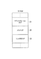
図3は、プリンタコントローラ5のRAM27bの構成を概略的に示した図である。このRAM27bには、サブコンフィグレーションエリア37とコマンドエリア38が設けられている。まず、コマンドエリア38について以下に説明する。このコマンドエリア38は、自デバイス5とPCIバス2を介して接続された他のデバイス3、4、又は6が自デバイス5に対するコマンドやレスポンス、データサイズの小さいデータ(例えば、104バイト未満のデータ)等を書込むための領域であり、プリンタコントローラ5がPCIバス2を介して通信可能なデバイス毎に複数の領域に論理的に分割されている。このコマンドエリア38は、本実施形態においては、MFPコントローラ用コマンドエリア39と、カラー画像処理ボード用コマンドエリア40と、ネットワークボード用コマンドエリア41と、追加デバイス用コマンドエリア42と、に論理的に分割されている。   FIG. 3 is a diagram schematically showing the configuration of the RAM 27 b of the printer controller 5. The RAM 27b is provided with a sub-configuration area 37 and a command area 38. First, the command area 38 will be described below. In this command area 38, the other device 3, 4 or 6 connected to the own device 5 via the PCI bus 2 is a command or response to the own device 5, data having a small data size (for example, data of less than 104 bytes). ) Etc., and the printer controller 5 is logically divided into a plurality of areas for each device that can communicate via the PCI bus 2. In this embodiment, the command area 38 is logically divided into an MFP controller command area 39, a color image processing board command area 40, a network board command area 41, and an additional device command area 42. It is divided.

ここで、MFPコントローラ用コマンドエリア39は、MFPコントローラ3のPCIホストコントローラ11が制御部10の制御命令に基づいてPCIバス2を介してプリンタコントローラ5に対するコマンドやレスポンス等を書込む領域である。カラー画像処理ボード用コマンドエリア40は、カラー画像処理ボード4のPCIコントローラ26aが制御部25aの制御命令に基づいてPCIバス2を介してプリンタコントローラ5に対するコマンドやレスポンス等を書込む領域である。ネットワークボード用コマンドエリア41は、ネットワークボード6のPCIコントローラ26cが制御部25cの制御命令に基づいてPCIバス2を介してプリンタコントローラ5に対するコマンドやレスポンス等を書込む領域である。追加デバイス用コマンドエリア42は、通信システム1に新たなスレーブデバイスが追加された場合に、その追加されたスレーブデバイスのPCIコントローラがPCIバス2を介してプリンタコントローラ5に対するコマンドやレスポンス等を書込む領域であり、スレーブデバイスの追加(増設)に対応するために予め設けられた領域である。   Here, the MFP controller command area 39 is an area where the PCI host controller 11 of the MFP controller 3 writes commands, responses, and the like to the printer controller 5 via the PCI bus 2 based on the control command of the control unit 10. The color image processing board command area 40 is an area in which the PCI controller 26a of the color image processing board 4 writes commands, responses, and the like for the printer controller 5 via the PCI bus 2 based on the control command of the control unit 25a. The network board command area 41 is an area where the PCI controller 26c of the network board 6 writes commands, responses, and the like for the printer controller 5 via the PCI bus 2 based on the control command of the control unit 25c. In the additional device command area 42, when a new slave device is added to the communication system 1, the PCI controller of the added slave device writes a command, a response, and the like for the printer controller 5 via the PCI bus 2. This is an area that is provided in advance to cope with the addition (addition) of slave devices.

このように、プリンタコントローラ5のRAM27bには、PCIバス2を介して自デバイス5と接続された他のデバイス3、4、又は6がコマンドやレスポンス等の各種データを書込むためのエリア(領域)39乃至41が前記他のデバイス毎に設けられている。   As described above, the area (area) in which other devices 3, 4 or 6 connected to the self device 5 via the PCI bus 2 write various data such as commands and responses are stored in the RAM 27b of the printer controller 5. 39 to 41 are provided for each of the other devices.

そして、各デバイス毎のコマンドエリア39乃至42は、それぞれ更にヘッダエリアとデータエリアとに論理的に分割されているが、このヘッダエリアとデータエリアについて、ここではカラー画像処理ボード用コマンドエリア40を例にして説明する。カラー画像処理ボード用コマンドエリア40のヘッダエリア43には、ヘッダタイプ、コマンドメールボックスID、レスポンスメールボックスID、コマンドナンバー(コマンド)、データアドレス(先頭アドレス)、データカウント(データサイズ)等が、データエリア44には、データサイズの小さいデータやレスポンス等が、自デバイス5と接続された他のデバイス(この領域では、カラー画像処理ボード4)によって書込まれるようになっている。   The command areas 39 to 42 for each device are further logically divided into a header area and a data area. The header area and the data area are referred to as a color image processing board command area 40 here. An example will be described. The header area 43 of the color image processing board command area 40 includes a header type, a command mailbox ID, a response mailbox ID, a command number (command), a data address (start address), a data count (data size), and the like. In the data area 44, data having a small data size, responses, and the like are written by another device connected to the device 5 (in this area, the color image processing board 4).

ヘッダタイプは、コマンド送信側のデバイス(カラー画像処理ボード4)によるカラー画像処理ボード用コマンドエリア40の使用状況を示すメモリ情報であり、カラー画像処理ボード用コマンドエリア40が未使用であることを示す情報、カラー画像処理ボード用コマンドエリア40がプリンタコントローラ5に対するコマンドによって使用中であることを示す情報、又はカラー画像処理ボード用コマンドエリア40がプリンタコントローラ5に対するレスポンスによって使用中であることを示す情報のいずれかである。プリンタコントローラ5の制御部25bは、ローカルバス31を介してRAM27bにアクセスし、このヘッダエリア43のヘッダタイプを取得することにより、カラー画像処理ボード4によるカラー画像処理ボード用コマンドエリア40の使用状況を判断することができる。   The header type is memory information indicating the usage status of the command area 40 for the color image processing board by the device (color image processing board 4) on the command transmission side, and indicates that the command area 40 for the color image processing board is not used. Information indicating that the color image processing board command area 40 is being used by a command to the printer controller 5, or indicating that the color image processing board command area 40 is being used by a response to the printer controller 5. Any of the information. The control unit 25b of the printer controller 5 accesses the RAM 27b via the local bus 31 and obtains the header type of the header area 43, thereby using the color image processing board command area 40 by the color image processing board 4. Can be judged.

コマンドメールボックスIDは、コマンド発行(送信)側のデバイス(ここでは、カラー画像処理ボード4)がレスポンス待ちする場合のメールボックスIDであり、レスポンス待ちしない場合には、コマンドメールボックスIDとして「0」がセットされる。レスポンスメールボックスIDは、レスポンスを発行した側(カラー画像処理ボード4)がコマンド待ちする場合のメールボックスIDであり、コマンド待ちしない場合には、レスポンスメールボックスIDとして「0」がセットされる。   The command mailbox ID is a mailbox ID when the device on the command issuing (sending) side (here, the color image processing board 4) waits for a response, and when not waiting for a response, “0” is set as the command mailbox ID. Is set. The response mailbox ID is a mailbox ID when the side that issued the response (color image processing board 4) waits for a command. When the command does not wait for a command, “0” is set as the response mailbox ID.

コマンドナンバー(コマンド)は、ここでは、カラー画像処理ボード4がプリンタコントローラ5に対して要求する処理を示すスカラ値であり、プリンタコントローラ5の制御部25bは、ヘッダエリア43に書込まれているコマンドナンバーを取得して自デバイス5が実行すべき処理が何であるかを判別することができるようになっている。   Here, the command number (command) is a scalar value indicating a process requested by the color image processing board 4 to the printer controller 5, and the control unit 25 b of the printer controller 5 is written in the header area 43. By acquiring the command number, it is possible to determine what processing the device 5 should execute.

データアドレス(以下、「先頭アドレス」という。)は、PCI空間上のアドレスであり、一方のデバイスから他方のデバイスへデータを転送する場合に、転送すべきデータが格納されている場所の先頭を示すアドレス、又は、転送後のデータを書込むべき場所の先頭を示すアドレスである。例えば、カラー画像処理ボード4からプリンタコントローラ5へデータを転送する場合には、RAM27aにおいてその転送すべきデータが格納されている場所の先頭を示すアドレス、又はRAM27bにおいて転送後のデータを書込むべき場所の先頭を示すアドレスである。   The data address (hereinafter referred to as “head address”) is an address on the PCI space, and when data is transferred from one device to the other device, the head of the location where the data to be transferred is stored is stored. Or an address indicating the beginning of a location where data after transfer is to be written. For example, when data is transferred from the color image processing board 4 to the printer controller 5, the address indicating the head of the location where the data to be transferred is stored in the RAM 27a, or the transferred data should be written in the RAM 27b. This is the address that indicates the beginning of the place.

データカウント(データサイズ)は、コマンドエリア38以外の領域を使用してデータを転送する場合に、その転送すべきデータのデータサイズを示すものである。したがって、例えばカラー画像処理ボード4からプリンタコントローラ5へデータを転送する場合に、プリンタコントローラ5の制御部25bは、このヘッダエリア43の先頭アドレス及びデータカウントに基づいて、自デバイス5に転送されるべきデータがカラー画像処理ボード4のRAM27a上のどの位置に格納されているかを特定することができる。   The data count (data size) indicates the data size of data to be transferred when data is transferred using an area other than the command area 38. Therefore, for example, when data is transferred from the color image processing board 4 to the printer controller 5, the control unit 25 b of the printer controller 5 transfers the data to its own device 5 based on the head address and data count of the header area 43. It is possible to specify the position on the RAM 27a of the color image processing board 4 where the power data is stored.

データエリア44に書込まれるデータは、具体的には、カラー画像処理ボード4のPCIコントローラ26aがPCIバス2を介して書込んだデータサイズの小さいデータ(例えば、データサイズが104バイト未満のデータ)や、プリンタコントローラ5に対するカラー画像処理ボード4のレスポンス等である。なお、データエリア44の容量を超えるデータサイズが大きいデータは、RAM27bにおけるコマンドエリア38以外の領域に書込まれるようになっている。   Specifically, the data written in the data area 44 is data having a small data size (for example, data having a data size of less than 104 bytes) written by the PCI controller 26a of the color image processing board 4 via the PCI bus 2. ), The response of the color image processing board 4 to the printer controller 5, and the like. Note that data having a large data size exceeding the capacity of the data area 44 is written in an area other than the command area 38 in the RAM 27b.

また、MFPコントローラ用コマンドエリア39には、MFPコントローラ3のPCIホストコントローラ11によって、ネットワークボード用コマンドエリア41には、ネットワークボード6のPCIコントローラ26cによって、データの書込みを行うデバイスが異なる点を除いて、上記のカラー画像処理ボード用コマンドエリア40と同様の情報が書込まれるようになっている。   The MFP controller command area 39 is different from the PCI host controller 11 of the MFP controller 3, and the network board command area 41 is different from the PCI controller 26 c of the network board 6 except for devices for writing data. Thus, the same information as in the color image processing board command area 40 is written.

さらにまた、デバイス3、4、及び6についても、PCIバス2を介して自デバイスと接続された他のデバイスがコマンドやレスポンス等を書込むためのコマンドエリアがそれぞれ設けられているが、これらのデバイス3、4、及び6のコマンドエリアは、自デバイスに接続されてコマンドエリアに書込みを行うデバイスの組合わせが異なるだけで、図3に基づいて説明したコマンドエリア38と同様に構成されているため、その詳細な説明は省略する。   Furthermore, the devices 3, 4, and 6 are also provided with command areas for other devices connected to the own device via the PCI bus 2 to write commands and responses. The command areas of the devices 3, 4, and 6 are configured in the same manner as the command area 38 described with reference to FIG. 3 except that the combination of devices that are connected to the device and write to the command area is different. Therefore, the detailed description is abbreviate | omitted.

図4は、プリンタコントローラ5のRAM27bに設けられているサブコンフィグレーションエリア37を概略的に示した図である。図示するように、サブコンフィグレーションエリア37は、デバイス情報エリア46と、MFPコントローラ用エリア47と、カラー画像処理ボード用エリア48と、ネットワークボード用エリア49と、追加デバイス用エリア50と、に論理的に分割されている。   FIG. 4 is a diagram schematically showing a sub-configuration area 37 provided in the RAM 27b of the printer controller 5. As shown in the figure, the sub-configuration area 37 includes a device information area 46, an MFP controller area 47, a color image processing board area 48, a network board area 49, and an additional device area 50. Divided.

デバイス情報エリア46は、サブコンフィグレーションエリア37が設けられたRAM27bを備えるデバイス(プリンタコントローラ5)に関する情報が格納される領域であり、デバイスID、ユニット(Unit)番号、ステータス(Status)、コマンドエリアサイズ、コマンドエリア0オフセット、ユニット(Unit)管理アドレス等の情報が書込まれるようになっている。   The device information area 46 is an area for storing information on a device (printer controller 5) including the RAM 27b provided with the sub-configuration area 37, and includes a device ID, a unit number, a status, and a command area. Information such as the size, command area 0 offset, and unit management address is written.

デバイスIDは、このサブコンフィグレーションエリア37を有するデバイスの識別子であり、ここでは、プリンタコントローラ5を示す情報である。ユニット番号は、デバイス(ここでは、プリンタコントローラ5)がどのコマンドユニットを使うかを示す情報である。   The device ID is an identifier of a device having the sub-configuration area 37, and here is information indicating the printer controller 5. The unit number is information indicating which command unit is used by the device (here, the printer controller 5).

ステータスは、PCIコントローラ26bに内蔵されているコンフィグレーションレジスタに対する初期化処理が完了したか否かを示す情報である。PCIホストコントローラ11は、コンフィグレーションサイクルにおいてPCIコントローラ26bに内蔵されているコンフィグレーションレジスタのコンフィグレーション(初期化処理)を行ってPCIコントローラ26bの動作環境の設定を終えると、その旨の情報をステータスとしてデバイス情報エリア46に書込む。プリンタコントローラ5は、この情報の書込みを受けた後に、PCIコントローラ26bによってMFPコントローラ3のRAM13に設けられているユニット管理エリア23にアクセスすることができるようになっている。   The status is information indicating whether or not the initialization process for the configuration register built in the PCI controller 26b is completed. When the PCI host controller 11 performs configuration (initialization processing) of the configuration register built in the PCI controller 26b in the configuration cycle and completes the setting of the operating environment of the PCI controller 26b, the information indicating that fact is displayed in the status. Is written in the device information area 46. After receiving the writing of this information, the printer controller 5 can access the unit management area 23 provided in the RAM 13 of the MFP controller 3 by the PCI controller 26b.

コマンドエリアサイズは、コマンドエリア38のサイズ(容量)を示す情報である。コマンドエリア0オフセットは、サブコンフィグレーションエリア37の先頭アドレスからのオフセットにより、コマンドエリア38の先頭アドレスを示した情報である。他のデバイス(カラー画像処理ボード4やネットワークボード6)は、サブコンフィグレーションエリア37にアクセスできた場合に、デバイス情報エリア46からコマンドエリアサイズ及びコマンドエリア0オフセットの情報を読み出すことにより、プリンタコントローラ5との間で通信を行うために必要な情報であるコマンドエリア38の位置情報を取得することができる。これにより、RAM27bにおけるコマンドエリア38の場所(PCIメモリ空間アドレス)を特定することができる。   The command area size is information indicating the size (capacity) of the command area 38. The command area 0 offset is information indicating the start address of the command area 38 by the offset from the start address of the subconfiguration area 37. When other devices (the color image processing board 4 and the network board 6) can access the sub-configuration area 37, the printer controller reads the command area size and command area 0 offset information from the device information area 46. The position information of the command area 38, which is information necessary for communication with the terminal 5, can be acquired. Thereby, the location (PCI memory space address) of the command area 38 in the RAM 27b can be specified.

ユニット管理アドレスは、ホストデバイスであるMFPコントローラ3のRAM13に設けられているユニット管理エリア23のPCI空間上のアドレスである。このユニット管理アドレスは、PCIコントローラ26bのコンフィグレーションレジスタに対するコンフィグレーションを終えたPCIホストコントローラ11によって書込まれる。   The unit management address is an address on the PCI space of the unit management area 23 provided in the RAM 13 of the MFP controller 3 which is a host device. This unit management address is written by the PCI host controller 11 which has finished the configuration for the configuration register of the PCI controller 26b.

MFPコントローラ用エリア47は、MFPコントローラ3がプリンタコントローラ5との通信に必要な情報やプリンタコントローラ5に対して割込みを発生させる際に割込み要因を書込む領域であり、MFPコントローラ3専用の領域である。カラー画像処理ボード用エリア48は、カラー画像処理ボード4がプリンタコントローラ5との通信に必要な情報やプリンタコントローラ5に対して割込みを発生させる際に割込み要因を書込む領域であり、カラー画像処理ボード4専用の領域である。ネットワークボード用エリア49は、ネットワークボード6がプリンタコントローラ5との通信に必要な情報やプリンタコントローラ5に対して割込みを発生させる際に割込み要因を書込む領域であり、ネットワークボード6専用の領域である。   The MFP controller area 47 is an area for writing information necessary for the MFP controller 3 to communicate with the printer controller 5 and an interrupt factor when generating an interrupt to the printer controller 5. is there. The color image processing board area 48 is an area where the color image processing board 4 writes information necessary for communication with the printer controller 5 and an interrupt factor when the printer controller 5 generates an interrupt. This is a dedicated area for the board 4. The network board area 49 is an area for writing information necessary for the network board 6 to communicate with the printer controller 5 and an interrupt factor when generating an interrupt to the printer controller 5. is there.

これらのMFPコントローラ用エリア47、カラー画像処理ボード用エリア48、ネットワークボード用エリア49、又は追加デバイス用エリア50には、受信コマンドバージョン(RxCommandVersion)、TxデバイスID、及び初期化ステータス(Status)の通信に必要な情報が通信準備の際に書込まれ、通信準備が完了して実際に通信が行われる際に、割込み要因が書込まれる(セットされる)ようになっている。   In these MFP controller area 47, color image processing board area 48, network board area 49, or additional device area 50, the received command version (RxCommandVersion), Tx device ID, and initialization status (Status) are stored. Information necessary for communication is written at the time of communication preparation, and an interrupt factor is written (set) when communication preparation is completed and communication is actually performed.

カラー画像処理ボード用エリア48を例にして説明すると、受信コマンドバージョンは、カラー画像処理ボード4によってコマンドエリア38(詳しくはカラー画像処理ボード用コマンドエリア40)に書込まれるコマンドのバージョンを示す情報であり、コマンドの追加に対応できるようになっている。制御部25bは、通信準備の際にこの受信コマンドバージョンを読み出してコマンドエリア38に書込まれるコマンドのバージョンを認識する。TxデバイスIDは、受信コマンドバージョン等が書込まれるエリアに書込みを行うデバイスの識別子であり、ここではカラー画像処理ボード4を示す情報である。   The color image processing board area 48 will be described as an example. The received command version is information indicating the version of the command written by the color image processing board 4 in the command area 38 (specifically, the color image processing board command area 40). It can handle the addition of commands. The control unit 25b reads the received command version when preparing for communication, and recognizes the version of the command written in the command area 38. The Tx device ID is an identifier of a device that performs writing in an area in which a received command version or the like is written, and is information indicating the color image processing board 4 here.

初期化ステータスは、プリンタコントローラ5がPCIバス2に未接続であることを示す情報、カラー画像処理ボード用エリア48への通信に必要な情報の書込みが完了したことを示す情報、又は、カラー画像処理ボード4との通信準備が完了したことを示す情報のいずれかである。プリンタコントローラ5が未接続である場合には、その旨を示す情報が制御部25bにより書込まれており、カラー画像処理ボード4のPCIコントローラ26aは、通信に必要な情報、すなわち受信コマンドバージョン及びTxデバイスIDの書込みを行った後に、初期化ステータスを通信準備に必要な情報の書込みが完了したことを示す情報に書換える。そして、プリンタコントローラ5の制御部25bは、初期化ステータスから通信に必要な情報が書込まれたと判断すると、受信コマンドバージョンの読み出しを行い、初期化ステータスを通信準備が完了したことを示す情報に書換える。このように、カラー画像処理ボード4とプリンタコントローラ5との間で通信準備が行われるようになっている。なお、カラー画像処理ボード4は、通信準備を行う際に、コマンドエリアサイズやコマンドエリア0オフセットの読み出しも併せて行う。   The initialization status includes information indicating that the printer controller 5 is not connected to the PCI bus 2, information indicating that writing of information necessary for communication to the color image processing board area 48 has been completed, or a color image Any of the information indicating that preparation for communication with the processing board 4 has been completed. When the printer controller 5 is not connected, information indicating that is written by the control unit 25b, and the PCI controller 26a of the color image processing board 4 receives information necessary for communication, that is, a received command version and After writing the Tx device ID, the initialization status is rewritten with information indicating that writing of information necessary for communication preparation has been completed. When the control unit 25b of the printer controller 5 determines that information necessary for communication is written from the initialization status, the control unit 25b reads the received command version, and sets the initialization status to information indicating that the communication preparation is completed. rewrite. In this manner, communication preparation is performed between the color image processing board 4 and the printer controller 5. The color image processing board 4 also reads out the command area size and command area 0 offset when preparing for communication.

ところで、PCIコントローラ26bが内蔵するコンフィグレーションレジスタへは、MFPコントローラ3のPCIホストコントローラ11しかアクセスすることができないが、このように、PCIコントローラ26aやPCIコントローラ26cがアクセスすることができるRAM27bのサブコンフィグレーションエリア37に通信に必要な情報をセットしておくことにより、カラー画像処理ボード4やネットワークボード6がそれらの通信に必要な情報を取得してホストデバイス3を介することなく、プリンタコントローラ5と直接通信することが可能となる。   By the way, the configuration register built in the PCI controller 26b can be accessed only by the PCI host controller 11 of the MFP controller 3, but in this way, the sub-RAM of the RAM 27b that can be accessed by the PCI controller 26a and the PCI controller 26c. By setting information necessary for communication in the configuration area 37, the color image processing board 4 and the network board 6 acquire information necessary for such communication, and the printer controller 5 does not pass through the host device 3. It is possible to communicate directly with.

割込み要因は、カラー画像処理ボード4がプリンタコントローラ5に対して割込みを発生させる際に、その要因を示す情報である。ここで、割込み要因としては、カラー画像処理ボード用コマンドエリア40に書込まれたコマンドやレスポンスの読み出しを要求する割込み要因(REQ)と、プリンタコントローラ5によってカラー画像処理ボード4のRAM27aのコマンドエリアに書込まれたコマンドやレスポンスの読み出しが完了したことを通知するための割込み要因(ACK)と、プリンタコントローラ5にリセットを要求するための割込み要因(RESET)と、同期を図るための割込み要因(SYNC)が用意されている。   The interrupt factor is information indicating the factor when the color image processing board 4 generates an interrupt to the printer controller 5. Here, as interrupt factors, an interrupt factor (REQ) for requesting reading of a command or response written in the color image processing board command area 40, and a command area of the RAM 27 a of the color image processing board 4 by the printer controller 5 are used. An interrupt factor (ACK) for notifying that the reading of the command or response written in is completed, an interrupt factor (RESET) for requesting the printer controller 5 to reset, and an interrupt factor for achieving synchronization (SYNC) is prepared.

例えば、カラー画像処理ボード4がカラー画像処理ボード用コマンドエリア40にコマンドを書込んでプリンタコントローラ5に割込みを発生させる場合、PCIコントローラ26aは、カラー画像処理ボード用エリア48の割込み要因(REQ)に「1」を書込み、割込みコントロールレジスタ12にプリンタコントローラ5への割込み要求を書込む。これに対し、割込みコントロールレジスタ12から割込み信号線18を介してプリンタコントローラ5の制御部25bへ割込み信号が送信される。これを受けて、制御部25bは、サブコンフィグレーションエリア37から割込み要因として「1」がセットされている領域を検索する。そして、カラー画像処理ボード用エリア48の割込み要因(REQ)として「1」がセットされていることを検出すると、カラー画像処理ボード用コマンドエリア40にコマンドが書込まれていると判断し、カラー画像処理ボード用コマンドエリア40からコマンドを読み出し、そのコマンドに対応する処理を実行する。そして、割込み要因をクリアする。すなわち、割込み要因(REQ)を「1」から「0」に書換える。   For example, when the color image processing board 4 writes a command in the color image processing board command area 40 and causes the printer controller 5 to generate an interrupt, the PCI controller 26 a causes the interrupt factor (REQ) in the color image processing board area 48. "1" is written in the interrupt control register 12, and an interrupt request to the printer controller 5 is written in the interrupt control register 12. In response to this, an interrupt signal is transmitted from the interrupt control register 12 to the control unit 25 b of the printer controller 5 through the interrupt signal line 18. In response to this, the control unit 25b searches the sub-configuration area 37 for an area where “1” is set as an interrupt factor. When it is detected that “1” is set as the interrupt factor (REQ) of the color image processing board area 48, it is determined that the command is written in the color image processing board command area 40, and the color A command is read from the image processing board command area 40, and processing corresponding to the command is executed. Then, the interrupt factor is cleared. That is, the interrupt factor (REQ) is rewritten from “1” to “0”.

このように、カラー画像処理ボード用エリア48には、カラー画像処理ボード4がプリンタコントローラ5と通信を行うために必要な情報がカラー画像処理ボード4のPCIコントローラ26aによって書込まれるようになっている。なお、受信コマンドバージョン、TxデバイスID、初期化ステータスについては、上記のように通信準備の段階で書込みが行われるようになっている。   Thus, in the color image processing board area 48, information necessary for the color image processing board 4 to communicate with the printer controller 5 is written by the PCI controller 26a of the color image processing board 4. Yes. The received command version, Tx device ID, and initialization status are written at the stage of communication preparation as described above.

また、MFPコントローラ用エリア47及びネットワークボード用エリア49についても、書込みを行うデバイスが異なる点を除いて、同様の情報が書込まれるようになっている。なお、このようなサブコンフィグレーションエリアは、全てのデバイス3乃至6のメモリ(RAM)にも設けられているが、いずれのデバイスのサブコンフィグレーションエリアも構成は同じで、サブコンフィグレーションエリアに受信コマンドバージョンやTxデバイスID等の書込みを行うデバイスの組合わせが異なるだけであるため、他のデバイス3、4、及び6のサブコンフィグレーションエリアについては、その説明を省略する。   The MFP controller area 47 and the network board area 49 are also written with the same information except that the writing device is different. Such a subconfiguration area is also provided in the memory (RAM) of all the devices 3 to 6, but the subconfiguration area of any device has the same configuration and is received by the subconfiguration area. Since only the combination of devices for writing the command version, Tx device ID, etc. is different, the description of the subconfiguration areas of the other devices 3, 4, and 6 is omitted.

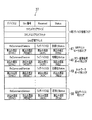
図5は、ホストデバイスであるMFPコントローラ3のRAM13に設けられているユニット管理エリア23を例示した図である。図示するように、ユニット管理エリア23は、ユニット管理情報エリア52と、MFPコントローラ用デバイス情報エリア53と、カラー画像処理ボード用デバイス情報エリア54と、プリンタコントローラ用デバイス情報エリア55と、ネットワークボード用デバイス情報エリア56と、追加デバイス用デバイス情報エリア57と、に論理的に分割されている。   FIG. 5 is a diagram illustrating a unit management area 23 provided in the RAM 13 of the MFP controller 3 which is a host device. As illustrated, the unit management area 23 includes a unit management information area 52, an MFP controller device information area 53, a color image processing board device information area 54, a printer controller device information area 55, and a network board. A device information area 56 and a device information area 57 for additional devices are logically divided.

ユニット管理情報エリア52には、ホストステータス(Host Status)及びコマンドエリアサイズがPCIホストコントローラ11によって書込まれるようになっている。ホストステータスは、MFPコントローラ3がスレーブデバイス4乃至6の初期化処理(コンフィグレーション)の実行中であることを示す情報、又は、MFPコントローラ3が全てのスレーブデバイス4乃至6の初期化処理を完了したことを示す情報のいずれかである。コマンドエリアサイズは、RAM13に設けられているコマンドエリア22のサイズ(容量)を示す情報である。   In the unit management information area 52, the host status and the command area size are written by the PCI host controller 11. The host status is information indicating that the MFP controller 3 is executing initialization processing (configuration) of the slave devices 4 to 6, or the MFP controller 3 has completed initialization processing of all the slave devices 4 to 6. It is one of the information indicating that it has been done. The command area size is information indicating the size (capacity) of the command area 22 provided in the RAM 13.

MFPコントローラ用デバイス情報エリア53、カラー画像処理ボード用デバイス情報エリア54、プリンタコントローラ用デバイス情報エリア55、及びネットワークボード用デバイス情報エリア56には、デバイスID、ユニット(Unit)番号、ステータス(Status)、サブコンフィグレーションエリアPCIメモリ空間アドレス等がPCIホストコントローラ11によって書込まれるようになっている。   An MFP controller device information area 53, a color image processing board device information area 54, a printer controller device information area 55, and a network board device information area 56 include a device ID, a unit number, and a status. The sub-configuration area PCI memory space address and the like are written by the PCI host controller 11.

デバイスID及びユニット番号は、スレーブデバイスが有するサブコンフィグレーションエリアからPCIホストコントローラ11が取得した情報である。ステータスは、スレーブデバイスを検出していないことを示す情報、又はスレーブデバイスを検出済であること、すなわちスレーブデバイスの初期化処理が完了していること、を示す情報のいずれか一方の情報である。サブコンフィグレーションエリアPCIメモリ空間アドレスは、スレーブデバイスのRAM27に設けられているサブコンフィグレーションエリアのPCIメモリ空間上の先頭アドレスである。   The device ID and unit number are information acquired by the PCI host controller 11 from the subconfiguration area of the slave device. The status is one of information indicating that the slave device has not been detected or information indicating that the slave device has been detected, that is, the initialization processing of the slave device has been completed. . The subconfiguration area PCI memory space address is the head address on the PCI memory space of the subconfiguration area provided in the RAM 27 of the slave device.

例えば、PCIホストコントローラ11は、プリンタコントローラ5のPCIコントローラ26bに内蔵されているコンフィグレーションレジスタのコンフィグレーション(初期化処理)を完了し、MFPコントローラ用エリア47に受信コマンドバージョン、TxデバイスID、及び初期化が完了したことを示す情報を初期化ステータスとして書込む。次に、サブコンフィグレーションエリア37から取得したデバイス情報、すなわち、デバイスID、ユニット番号、サブコンフィグレーションエリア37のサブコンフィグレーションエリアPCIメモリ空間アドレスをプリンタコントローラ用デバイス情報エリア55に書込む。そして、ステータスとして検出済みを示す情報を書込む。このようにしてユニット管理エリア23のプリンタコントローラ用デバイス情報エリア55にプリンタコントローラ5にアクセスするために必要な情報がセットされると、スレーブデバイス(カラー画像処理ボード4やネットワークボード6)は、プリンタコントローラ用デバイス情報エリア55に書込まれている情報を参照してプリンタコントローラ5のサブコンフィグレーションエリア37にアクセスすることができる。すなわち、プリンタコントローラ5を認識して、上記のようなプリンタコントローラ5との通信準備を行うことができる。   For example, the PCI host controller 11 completes the configuration (initialization process) of the configuration register built in the PCI controller 26b of the printer controller 5, and the received command version, Tx device ID, and Information indicating that the initialization is completed is written as an initialization status. Next, the device information acquired from the subconfiguration area 37, that is, the device ID, the unit number, and the subconfiguration area PCI memory space address of the subconfiguration area 37 are written in the device information area 55 for the printer controller. Then, information indicating detection is written as the status. When information necessary for accessing the printer controller 5 is set in the printer controller device information area 55 of the unit management area 23 in this way, the slave device (the color image processing board 4 or the network board 6) The sub-configuration area 37 of the printer controller 5 can be accessed with reference to the information written in the controller device information area 55. That is, it is possible to recognize the printer controller 5 and prepare for communication with the printer controller 5 as described above.

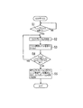
以下、通信システム1起動時のコンフィグレーションサイクルにおいて、ホストデバイスであるMFPコントローラ3によって行われる処理動作について、図6に示すフローチャート及び図7に基づいて説明する。なお、図6に示すフローチャートに基づいて説明するMFPコントローラ3の処理動作は、図外のROMに格納されているプログラムに基づいて制御部10が発行する命令に従って行われる。また、ここでは、第1スレーブデバイスがプリンタコントローラ5で、第2スレーブデバイスがカラー画像処理ボード4である場合について主に説明するが、第1スレーブデバイスと第2スレーブデバイスの組合わせはこれに限定されるものではない。すなわち、第1スレーブデバイスと第2スレーブデバイスの組合わせは任意であり、例えば、第1スレーブデバイスがカラー画像処理ボード4で第2スレーブデバイスがプリンタコントローラ5であってもよい。   Hereinafter, processing operations performed by the MFP controller 3 serving as the host device in the configuration cycle when the communication system 1 is activated will be described with reference to the flowchart shown in FIG. 6 and FIG. Note that the processing operation of the MFP controller 3 described based on the flowchart shown in FIG. 6 is performed according to a command issued by the control unit 10 based on a program stored in a ROM (not shown). Here, the case where the first slave device is the printer controller 5 and the second slave device is the color image processing board 4 will be mainly described. However, the combination of the first slave device and the second slave device is described here. It is not limited. That is, the combination of the first slave device and the second slave device is arbitrary. For example, the first slave device may be the color image processing board 4 and the second slave device may be the printer controller 5.

MFPコントローラ3のPCIホストコントローラ11は、通信システム1起動時のコンフィグレーションサイクルにおいて、PCIバス2へのスレーブデバイスの接続の有無を監視し、スレーブデバイスを検出したか否かを判断する(S1)。このように、MFPコントローラ3のPCIホストコントローラ11は、PCIバス2に接続されているプリンタコントローラ5(第1スレーブデバイス)を検出する。   The PCI host controller 11 of the MFP controller 3 monitors whether or not a slave device is connected to the PCI bus 2 in the configuration cycle when the communication system 1 is activated, and determines whether or not a slave device has been detected (S1). . As described above, the PCI host controller 11 of the MFP controller 3 detects the printer controller 5 (first slave device) connected to the PCI bus 2.

ここで、PCIホストコントローラ11は、プリンタコントローラ5を検出したと判断した場合(S1:YES)、コンフィグレーションを実行する(S2)。具体的には、PCIコントローラ26bに内蔵されているコンフィグレーションレジスタ60にアクセスし、ベースアドレスの書込みや、デバイスID、バージョン情報等の読み出しを行う。なお、ここで行われるコンフィグレーションレジスタ60に対するコンフィグレーションは、PCI規格に準拠したものであるため、その詳細な説明は省略する。   Here, if the PCI host controller 11 determines that the printer controller 5 has been detected (S1: YES), the PCI host controller 11 executes configuration (S2). Specifically, the configuration register 60 built in the PCI controller 26b is accessed to write the base address and read the device ID, version information, and the like. Note that the configuration for the configuration register 60 performed here conforms to the PCI standard, and thus detailed description thereof is omitted.

続いて、PCIホストコントローラ11は、S2のコンフィグレーションによりプリンタコントローラ5から取得したデバイス情報をユニット管理エリア23にセットする(S3)。ところで、MFPコントローラ3は、プリンタコントローラ5から取得したデバイス情報を格納するユニット管理エリア23が設けられたRAM13を備えており、PCIホストコントローラ11は、S2においてコンフィグレーションレジスタ60から取得したデバイスID、ユニット番号、プリンタコントローラ5のRAM27bに設けられているサブコンフィグレーションエリア37のPCIメモリ空間上のアドレス(先頭アドレス)をユニット管理エリア23内のプリンタコントローラ用デバイス情報エリア55に書込む。そして、プリンタコントローラ用デバイス情報エリア55のステータスをプリンタコントローラ5を検出済みであることを示す情報に書換える。   Subsequently, the PCI host controller 11 sets the device information acquired from the printer controller 5 by the configuration of S2 in the unit management area 23 (S3). The MFP controller 3 includes a RAM 13 provided with a unit management area 23 for storing device information acquired from the printer controller 5. The PCI host controller 11 includes a device ID acquired from the configuration register 60 in S2, The unit number and the address (start address) in the PCI memory space of the sub-configuration area 37 provided in the RAM 27 b of the printer controller 5 are written in the printer controller device information area 55 in the unit management area 23. Then, the status in the printer controller device information area 55 is rewritten with information indicating that the printer controller 5 has been detected.

次に、PCIホストコントローラ11は、コンフィグレーションが完了していないスレーブデバイスがあるか否かを判断する(S4)。すなわち、S2及びS3の処理動作を行っていないスレーブデバイスがあるか否かを判断する。なお、この判断処理は、ユニット管理エリア23のデバイス情報エリア53乃至56の各エリアのステータスを参照することにより判断することができる。ここで、コンフィグレーションが完了していないスレーブデバイスがあると判断した場合(S4:YES)、そのスレーブデバイス(カラー画像処理ボード4やネットワークボード6)に対して、プリンタコントローラ5を例として説明したのと同様に、S2及びS3の処理動作を行う。   Next, the PCI host controller 11 determines whether there is a slave device whose configuration has not been completed (S4). That is, it is determined whether there is a slave device that has not performed the processing operations of S2 and S3. This determination process can be determined by referring to the statuses of the device information areas 53 to 56 in the unit management area 23. If it is determined that there is a slave device that has not been configured (S4: YES), the printer controller 5 has been described as an example for the slave device (color image processing board 4 or network board 6). Similarly to the above, the processing operations of S2 and S3 are performed.

逆に、コンフィグレーションが完了していないスレーブデバイスはないと判断した場合(S4:NO)、すなわち、ここでは、デバイス情報エリア53乃至56の全てについて、デバイスID、ユニット番号、及びサブコンフィグレーションエリアPCIメモリ空間アドレスの書込みと、ステータスの変更が完了したと判断した場合、S5に進む。   Conversely, when it is determined that there is no slave device that has not been configured (S4: NO), that is, here, for all the device information areas 53 to 56, the device ID, unit number, and subconfiguration area If it is determined that the writing of the PCI memory space address and the status change have been completed, the process proceeds to S5.

すなわち、PCIホストコントローラ11は、各スレーブデバイスのサブコンフィグレーションエリアにユニット管理アドレスを書込むとともに、コンフィグレーションの完了を各スレーブデバイスに通知する(S5)。言い換えれば、検出したスレーブデバイスにアクセスするために必要な情報を取得したことを各スレーブデバイスに通知する。   That is, the PCI host controller 11 writes the unit management address in the sub-configuration area of each slave device and notifies each slave device of the completion of configuration (S5). In other words, each slave device is notified that information necessary for accessing the detected slave device has been acquired.

具体的には、プリンタコントローラ5に対し、サブコンフィグレーションエリア37内のデバイス情報エリア46にユニット管理エリア23の先頭アドレスであるユニット管理アドレスを書込むとともに、デバイス情報エリア46のステータスをコンフィグレーション(初期化処理)が完了したことを示す情報に書換える。そして、このようなプリンタコントローラ5のサブコンフィグレーションエリア37に対して行われるのと同様の処理を、カラー画像処理ボード4のRAM27a及びネットワークボード6のRAM27cにそれぞれ設けられているサブコンフィグレーションエリア(不図示)に対して行う。   Specifically, the unit management address which is the head address of the unit management area 23 is written in the device information area 46 in the sub-configuration area 37 to the printer controller 5 and the status of the device information area 46 is configured ( It is rewritten with information indicating that the initialization process has been completed. Then, the same processing as that performed for the sub-configuration area 37 of the printer controller 5 is performed in the sub-configuration areas (respectively provided in the RAM 27a of the color image processing board 4 and the RAM 27c of the network board 6). (Not shown).

このように、MFPコントローラ3のPCIホストコントローラ11は、S2乃至S5の一連の処理動作を行うことにより、検出した第1スレーブデバイス(例えばプリンタコントローラ5)にアクセスするために必要なデバイス情報を当該第1スレーブデバイスから取得してその旨を第2スレーブデバイス(例えば、カラー画像処理ボード4)に通知する。   As described above, the PCI host controller 11 of the MFP controller 3 performs a series of processing operations from S2 to S5 to obtain device information necessary for accessing the detected first slave device (for example, the printer controller 5). Obtained from the first slave device and notifies the second slave device (for example, the color image processing board 4) to that effect.

以上の説明から明らかなように、例えば、カラー画像処理ボード4の制御部25aは、RAM27aに設けられたサブコンフィグレーションエリアからユニット管理アドレスを読み出し、PCIコントローラ26aによりMFPコントローラ3のRAM13に設けられているユニット管理エリア23にアクセスすることができる。そして、ユニット管理エリア23のプリンタコントローラ用デバイス情報エリア55から、プリンタコントローラ5のデバイスID、ユニット番号、及びサブコンフィグレーションエリアPCIメモリ空間アドレスを取得することができる。また、ネットワークボード用デバイス情報エリア56から、ネットワークボード6のデバイスID、ユニット番号、及びサブコンフィグレーションエリアPCIメモリ空間アドレスを取得することができる。つまり、プリンタコントローラ5やネットワークボード6にアクセスするために必要な情報をホストデバイス3から簡単に取得することができる。   As is apparent from the above description, for example, the control unit 25a of the color image processing board 4 reads the unit management address from the subconfiguration area provided in the RAM 27a, and is provided in the RAM 13 of the MFP controller 3 by the PCI controller 26a. The unit management area 23 can be accessed. The device ID, unit number, and subconfiguration area PCI memory space address of the printer controller 5 can be acquired from the printer controller device information area 55 in the unit management area 23. Further, the device ID, unit number, and subconfiguration area PCI memory space address of the network board 6 can be acquired from the network board device information area 56. That is, information necessary for accessing the printer controller 5 and the network board 6 can be easily obtained from the host device 3.

次に、上記のようにコンフィグレーションの完了が通知された場合に、スレーブデバイスにおいて行われる処理動作について、図7及び図8に示すフローチャートに基づいて説明する。ところで、図8のフローチャートに示す処理動作は、カラー画像処理ボード4、プリンタコントローラ5、及びネットワークボード6の全てのスレーブデバイスにおいて行われるが、ここでは、カラー画像処理ボード4が図8に示す処理動作を行う場合を例として以下に説明する。なお、図8に示すフローチャートに基づいて説明するカラー画像処理ボード4の処理動作は、カラー画像処理ボード4が備える図外のROMに格納されているプログラムに基づいて制御部25aが発行する命令に従って行われる。   Next, processing operations performed in the slave device when the completion of configuration is notified as described above will be described based on the flowcharts shown in FIGS. The processing operation shown in the flowchart of FIG. 8 is performed in all slave devices of the color image processing board 4, the printer controller 5, and the network board 6. Here, the color image processing board 4 performs the processing shown in FIG. The case of performing the operation will be described below as an example. The processing operation of the color image processing board 4 described based on the flowchart shown in FIG. 8 is performed according to a command issued by the control unit 25a based on a program stored in a ROM (not shown) provided in the color image processing board 4. Done.

まず、カラー画像処理ボード4の制御部25aは、コンフィグレーションの完了通知があったか否かを判断する(S11)。具体的には、図示しないが、RAM27aに設けられているサブコンフィグレーションエリアのデバイス情報エリアにユニット管理アドレスが書込まれ、デバイス情報エリアのステータスが、コンフィグレーション(初期化処理)が完了したことを示す情報に書換えられているか否かを判断する。   First, the control unit 25a of the color image processing board 4 determines whether a configuration completion notification has been received (S11). Specifically, although not shown, the unit management address is written in the device information area of the sub-configuration area provided in the RAM 27a, and the status of the device information area indicates that the configuration (initialization process) has been completed. It is determined whether or not the information has been rewritten.

ここで、コンフィグレーションの完了通知があったと判断した場合(S11:YES)、すなわち、デバイス情報エリアにユニット管理アドレスが書込まれ、ステータスがコンフィグレーションが完了したことを示す情報に書換えられていると判断した場合、ホストデバイス3のユニット管理エリア23にアクセスする(S12)。すなわち、制御部25aは、デバイス情報エリアに書込まれているユニット管理アドレスを読み出し、PCIコントローラ26aは、制御部25aが読み出したユニット管理アドレス、すなわち、RAM13のユニット管理エリア23にアクセスする。   Here, when it is determined that there is a configuration completion notification (S11: YES), that is, the unit management address is written in the device information area, and the status is rewritten with information indicating that the configuration is completed. If it is determined, the unit management area 23 of the host device 3 is accessed (S12). That is, the control unit 25a reads the unit management address written in the device information area, and the PCI controller 26a accesses the unit management address read by the control unit 25a, that is, the unit management area 23 of the RAM 13.

次に、カラー画像処理ボード4のPCIコントローラ26aは、他のデバイス、すなわち、MFPコントローラ3、プリンタコントローラ5、及びネットワークボード6のデバイス情報を取得する(S13)。具体的には、アクセスしたユニット管理エリア23内のMFPコントローラ用デバイス情報エリア53、プリンタコントローラ用デバイス情報エリア55、及びネットワークボード用デバイス情報エリア56から、デバイスID、ユニット番号、及びサブコンフィグレーションエリアPCIメモリ空間アドレスを読み出す。   Next, the PCI controller 26a of the color image processing board 4 acquires device information of other devices, that is, the MFP controller 3, the printer controller 5, and the network board 6 (S13). Specifically, the device ID, unit number, and sub-configuration area from the MFP controller device information area 53, the printer controller device information area 55, and the network board device information area 56 in the accessed unit management area 23 are displayed. Read the PCI memory space address.

このように、第2スレーブデバイス(カラー画像処理ボード4)は、コンフィグレーションの完了通知、すなわち、第1スレーブデバイス(プリンタコントローラ5)からデバイス情報を取得したことを示す通知を受けた場合に、ホストデバイス(MFPコントローラ3)からデバイス情報を取得する。なお、カラー画像処理ボード4のPCIコントローラ26aは、上記の通知を受けた場合に、RAM13のユニット管理エリア23からデバイス情報を読み出すことにより、ホストデバイス3からデバイス情報を取得するものであるため、他のデバイスのデバイス情報を容易に取得することができる。   As described above, when the second slave device (color image processing board 4) receives a configuration completion notification, that is, a notification indicating that device information has been acquired from the first slave device (printer controller 5), Device information is acquired from the host device (MFP controller 3). Note that the PCI controller 26a of the color image processing board 4 acquires device information from the host device 3 by reading the device information from the unit management area 23 of the RAM 13 when receiving the above notification. Device information of other devices can be easily acquired.

続いて、カラー画像処理ボード4のPCIコントローラ26aは、取得したデバイス情報に基づいて他のデバイスにアクセスし、そのデバイスとの間で通信準備を行う(S14)。例えば、プリンタコントローラ用デバイス情報エリア55から読み出したデバイスID、ユニット番号、及びサブコンフィグレーションエリアPCIメモリ空間アドレスに基づいてプリンタコントローラ5のRAM27bに設けられているサブコンフィグレーションエリア37にアクセスする。そして、サブコンフィグレーションエリア37内の自デバイス4専用の領域、すなわち、カラー画像処理ボード用エリア48に、受信コマンドバージョン及びTxデバイスID(カラー画像処理ボード4のデバイスID)を書込む。   Subsequently, the PCI controller 26a of the color image processing board 4 accesses another device based on the acquired device information and prepares for communication with the device (S14). For example, the sub-configuration area 37 provided in the RAM 27b of the printer controller 5 is accessed based on the device ID, unit number, and sub-configuration area PCI memory space address read from the printer controller device information area 55. Then, the received command version and the Tx device ID (device ID of the color image processing board 4) are written in the area dedicated to the own device 4 in the subconfiguration area 37, that is, the color image processing board area 48.

このように、カラー画像処理ボード4(第2スレーブデバイス)のPCIコントローラ26aは、取得したそのデバイス情報に基づいてプリンタコントローラ5(第1スレーブデバイス)にアクセスし、プリンタコントローラ5との間で通信準備を行う。   As described above, the PCI controller 26a of the color image processing board 4 (second slave device) accesses the printer controller 5 (first slave device) based on the acquired device information and communicates with the printer controller 5. Make preparations.

ところで、プリンタコントローラ5は、自デバイス5と接続された他のデバイスが情報を書込むための領域が他のデバイス毎に設けられたRAM27b、言い換えれば、図4に示すようなサブコンフィグレーションエリア37が設けられたRAM27bを備えており、カラー画像処理ボード4のPCIコントローラ26aは、プリンタコントローラ5のRAM27bに設けられたカラー画像処理ボード4専用の領域(カラー画像処理ボード用エリア48)に通信に必要な情報を書込み、デバイス情報エリア46からコマンドエリアサイズやコマンドエリア0オフセット等の情報を読み出すことにより、通信準備を行う。   By the way, the printer controller 5 has a RAM 27b in which an area for writing information to other devices connected to the self device 5 is provided for each other device, in other words, a sub-configuration area 37 as shown in FIG. The PCI controller 26a of the color image processing board 4 communicates with an area (color image processing board area 48) dedicated to the color image processing board 4 provided in the RAM 27b of the printer controller 5. Communication preparation is performed by writing necessary information and reading information such as a command area size and a command area 0 offset from the device information area 46.

そして、カラー画像処理ボード4の制御部25aは、S14の処理動作の後、通信準備が完了していないターゲットがあるか否かを判断する(S15)。すなわち、S13においてデバイス情報を取得した全てのデバイスに対して、プリンタコントローラ5を例に説明した上記S14の処理動作を行ったか否かを判断する。そして、通信準備が完了していないターゲットのデバイスがあると判断した場合(S15:YES)、そのターゲットのデバイスに対してS14の処理動作を行う。逆に、通信準備が完了していないターゲットがないと判断した場合(S15:NO)、処理を完了する。   Then, the control unit 25a of the color image processing board 4 determines whether there is a target for which communication preparation is not completed after the processing operation of S14 (S15). That is, it is determined whether or not the processing operation of S14 described with reference to the printer controller 5 has been performed for all devices that have acquired device information in S13. If it is determined that there is a target device that is not ready for communication (S15: YES), the processing operation of S14 is performed on the target device. Conversely, if it is determined that there is no target for which communication preparation has not been completed (S15: NO), the processing is completed.

なお、カラー画像処理ボード4を例にして説明した図8に示すフローチャートの処理動作は、プリンタコントローラ5、ネットワークボード6、そして、MFPコントローラ3によっても行われるようになっており、2つのデバイス間で、コマンドバージョン、TxデバイスID等の通信に必要な情報を書込む処理と、コマンドエリアサイズやコマンドエリア0オフセット等の通信に必要な情報を読み出す処理とが相互に行われるようになっている。   Note that the processing operation of the flowchart shown in FIG. 8 described by taking the color image processing board 4 as an example is also performed by the printer controller 5, the network board 6, and the MFP controller 3, and the operation between the two devices is performed. Thus, a process for writing information necessary for communication such as a command version and a Tx device ID and a process for reading information necessary for communication such as a command area size and a command area 0 offset are mutually performed. .

具体的には、カラー画像処理ボード4のPCIコントローラ26aがサブコンフィグレーションエリア37のカラー画像処理ボード用エリア48に通信に必要な情報を書込む処理及びデバイス情報エリア46から通信に必要な情報を読み出す処理と並行して、プリンタコントローラ5のPCIコントローラ26bがカラー画像処理ボード4のRAM27aに設けられているサブコンフィグレーションエリアのプリンタコントローラ用エリアに通信に必要な情報を書込む処理及びデバイス情報エリアから通信に必要な情報を読み出す処理が行われるようになっている。   Specifically, the PCI controller 26 a of the color image processing board 4 writes information necessary for communication in the color image processing board area 48 of the subconfiguration area 37 and information necessary for communication from the device information area 46. In parallel with the reading process, the PCI controller 26b of the printer controller 5 writes information necessary for communication to the printer controller area in the sub-configuration area provided in the RAM 27a of the color image processing board 4 and the device information area. A process for reading information necessary for communication is performed.

このように、2つのスレーブデバイス間で相互に通信に必要な情報の書込み及び読み出しを行って通信準備を行うことにより、ホストデバイス(MFPコントローラ3)を介することなく、スレーブデバイス同士が直接通信することが可能となる。   In this way, by writing and reading information necessary for communication between two slave devices and preparing for communication, the slave devices communicate directly with each other without going through the host device (MFP controller 3). It becomes possible.

以下、ホストデバイス(MFPコントローラ3)を介することなく、スレーブデバイス同士が直接通信する場合の一例として、コマンド送信側のカラー画像処理ボード4からコマンド受信側のプリンタコントローラ5に対して、コマンドとともにデータサイズの小さいデータが転送される場合の通信について図9のシーケンス図及び図10に基づいて説明する。   Hereinafter, as an example of the case where slave devices communicate directly with each other without going through the host device (MFP controller 3), data is transmitted together with commands from the color image processing board 4 on the command transmission side to the printer controller 5 on the command reception side. Communication when small-sized data is transferred will be described with reference to the sequence diagram of FIG. 9 and FIG.

なお、図9に示すカラー画像処理ボード4の処理動作は、カラー画像処理ボード4が備える図外のROMに格納されているプログラムに基づいて制御部25aが発行する命令に従って行われ、プリンタコントローラ5の処理動作は、プリンタコントローラ5が備える図外のROMに格納されているプログラムに基づいて制御部25bが発行する命令に従って行われる。   Note that the processing operation of the color image processing board 4 shown in FIG. 9 is performed according to a command issued by the control unit 25a based on a program stored in a ROM (not shown) provided in the color image processing board 4, and the printer controller 5 This processing operation is performed according to a command issued by the control unit 25b based on a program stored in a ROM (not shown) provided in the printer controller 5.

まず、コマンド送信側のカラー画像処理ボード4の制御部25aは、コマンド受信側のプリンタコントローラ5のカラー画像処理ボード用コマンドエリア40のセマフォを獲得する。具体的には、RAM27aの所定領域にカラー画像処理ボード用コマンドエリア40の使用権を獲得するための情報を書込んでカラー画像処理ボード用コマンドエリア40のヘッダエリア43とデータエリア44のセマフォを獲得する。   First, the control unit 25a of the color image processing board 4 on the command transmission side acquires a semaphore in the command area 40 for the color image processing board of the printer controller 5 on the command reception side. Specifically, information for acquiring the right to use the color image processing board command area 40 is written in a predetermined area of the RAM 27a, and the semaphores of the header area 43 and the data area 44 of the color image processing board command area 40 are set. To win.

そして、制御部25aは、カラー画像処理ボード用コマンドエリア40のヘッダエリア43にヘッダタイプ及びコマンド(コマンドナンバー)を書込む。具体的には、PCIコントローラ26aにより、カラー画像処理ボード用コマンドエリア40がコマンドにより使用中であることを示すヘッダタイプ、及びプリンタコントローラ5へ転送すべきデータの取扱いを示すコマンドをPCIバス2を介してPCIコントローラ26bに送信する。これに対し、PCIコントローラ26bは、受信したヘッダタイプ及びコマンドをローカルバス31を介してカラー画像処理ボード用コマンドエリア40のヘッダエリア43に書込む。   Then, the control unit 25a writes the header type and the command (command number) in the header area 43 of the color image processing board command area 40. Specifically, the PCI controller 26 a sends a command indicating the header type indicating that the color image processing board command area 40 is being used by the command and the handling of data to be transferred to the printer controller 5 to the PCI bus 2. To the PCI controller 26b. On the other hand, the PCI controller 26 b writes the received header type and command into the header area 43 of the color image processing board command area 40 via the local bus 31.

このように、カラー画像処理ボード4が、PCIコントローラ26aによって、プリンタコントローラ5のRAM27bに設けられたカラー画像処理ボード4専用のカラー画像処理ボード用コマンドエリア40にコマンドを書込む。   In this way, the color image processing board 4 writes a command to the color image processing board command area 40 dedicated to the color image processing board 4 provided in the RAM 27b of the printer controller 5 by the PCI controller 26a.

続いて、制御部25aは、転送すべきデータをカラー画像処理ボード用コマンドエリア40のデータエリア44に書込む。具体的には、PCIコントローラ26aにより、転送すべきデータをPCIバス2を介してPCIコントローラ26bに送信する。これに対し、PCIコントローラ26bは、受信したデータをローカルバス31を介してRAM27bのカラー画像処理ボード用コマンドエリア40のデータエリア44に書込む。なお、ここでは、コマンド及び転送すべきデータをカラー画像処理ボード用コマンドエリア40に書込んでいるが、コマンド以外のデータを転送する必要がない場合には、データエリア44への書込みは不要である。   Subsequently, the control unit 25a writes data to be transferred to the data area 44 of the command area 40 for the color image processing board. Specifically, the PCI controller 26a transmits data to be transferred to the PCI controller 26b via the PCI bus 2. On the other hand, the PCI controller 26b writes the received data into the data area 44 of the color image processing board command area 40 of the RAM 27b via the local bus 31. Here, the command and the data to be transferred are written in the command area 40 for the color image processing board. However, if it is not necessary to transfer data other than the command, the writing to the data area 44 is not necessary. is there.

カラー画像処理ボード4の制御部25aは、このようにしてカラー画像処理ボード用コマンドエリア40にコマンド及び転送すべきデータを書込むと、その旨をコマンド受信側のプリンタコントローラ5に通知するために、割込みを発生させる。具体的には、PCIコントローラ26aにより、プリンタコントローラ5に対して割込みを発生させるための割込み要因をRAM27bのサブコンフィグレーションエリア37内のカラー画像処理ボード用エリア48に書込む。詳しくは、カラー画像処理ボード用エリア48の割込み要因(REQ)を「0」から「1」に書換える。そして、MFPコントローラ3が備える割込みコントロールレジスタ12にプリンタコントローラ5への割込み要求を書込む。   When the control unit 25a of the color image processing board 4 writes the command and the data to be transferred in the color image processing board command area 40 in this manner, the control unit 25a notifies the printer controller 5 on the command receiving side of the fact. , Generate an interrupt. Specifically, the PCI controller 26a writes an interrupt factor for causing the printer controller 5 to generate an interrupt in the color image processing board area 48 in the sub-configuration area 37 of the RAM 27b. Specifically, the interrupt factor (REQ) of the color image processing board area 48 is rewritten from “0” to “1”. Then, an interrupt request to the printer controller 5 is written in the interrupt control register 12 provided in the MFP controller 3.

このようにして、カラー画像処理ボード4からプリンタコントローラ5への割込み要求が割込みコントロールレジスタ12にセットされると、割込みコントロールレジスタ12から割込み信号線18を介してプリンタコントローラ5の制御部25bへ割込み信号が送信される。これを受けて、制御部25bは、ローカルバス31を介してRAM27bのサブコンフィグレーションエリア37から「1」が書込まれている割込み要因を検索し、カラー画像処理ボード用エリア48の割込み要因(REQ)として「1」がセットされていることを検出することにより、カラー画像処理ボード用コマンドエリア40にコマンドが書込まれたことを判断することができる。   In this way, when an interrupt request from the color image processing board 4 to the printer controller 5 is set in the interrupt control register 12, the interrupt control register 12 interrupts the control unit 25b of the printer controller 5 via the interrupt signal line 18. A signal is transmitted. In response to this, the control unit 25b searches for an interrupt factor in which “1” is written from the sub-configuration area 37 of the RAM 27b via the local bus 31, and the interrupt factor (in the color image processing board area 48) ( By detecting that “1” is set as (REQ), it can be determined that the command has been written in the command area 40 for the color image processing board.

プリンタコントローラ5の制御部25bは、カラー画像処理ボード用コマンドエリア40のヘッダエリア43からコマンドを読み出すとともに、データエリア44からデータを読み出す。そして、データエリア44から読み出したデータに対して、ヘッダエリア43から読み出したコマンドに対応する処理を実行し、カラー画像処理ボード用コマンドエリア40からコマンド及びデータを読み出したことをコマンド送信側のカラー画像処理ボード4に通知するために、カラー画像処理ボード4に対して割込みを発生させる。なお、この割込みは、上記のカラー画像処理ボード4からプリンタコントローラ5への割込みと割込みの方向が逆となり、割込み要因が異なる点を除いてカラー画像処理ボード4からプリンタコントローラ5への割込みと同様に行われるため、ここでの詳細な説明は省略する。   The control unit 25 b of the printer controller 5 reads commands from the header area 43 of the color image processing board command area 40 and reads data from the data area 44. Then, processing corresponding to the command read from the header area 43 is executed on the data read from the data area 44, and the command transmission side color that the command and data are read from the command area 40 for the color image processing board is read. In order to notify the image processing board 4, an interrupt is generated for the color image processing board 4. This interrupt is the same as the interrupt from the color image processing board 4 to the printer controller 5 except that the interrupt direction is opposite to that of the interrupt from the color image processing board 4 to the printer controller 5 and the interrupt factor is different. Therefore, detailed description thereof is omitted here.

カラー画像処理ボード4の制御部25aは、プリンタコントローラ5からの割込みを受けると、カラー画像処理ボード用コマンドエリア40に書込んだコマンド及びデータがプリンタコントローラ5の制御部25bによって読み出されて不要になったと判断する。そして、ヘッダエリア43に、カラー画像処理ボード用コマンドエリア40が未使用であることを示すヘッダタイプを書込み、RAM27aの所定領域にカラー画像処理ボード用コマンドエリア40の使用権を返却するための情報を書込んでカラー画像処理ボード用コマンドエリア40のヘッダエリア43とデータエリア44のセマフォを返却して通信を完了する。   When the control unit 25a of the color image processing board 4 receives an interrupt from the printer controller 5, the command and data written in the color image processing board command area 40 are read out by the control unit 25b of the printer controller 5 and are not required. Judge that it became. Then, a header type indicating that the color image processing board command area 40 is unused is written in the header area 43, and information for returning the right to use the color image processing board command area 40 to a predetermined area of the RAM 27a. To return the semaphores of the header area 43 and the data area 44 of the command area 40 for the color image processing board and complete the communication.

このように、本実施形態に係る通信システム1では、スレーブデバイスが他のスレーブデバイスを容易に認識してスレーブデバイス同士が直接通信を行うことができる。そのため、例えば、データサイズの大きいカラー画像データをスレーブデバイス間で転送する場合に、ホストデバイス3を介することなく、効率よくカラー画像データを転送することができる。   Thus, in the communication system 1 according to the present embodiment, the slave device can easily recognize other slave devices and can directly communicate with each other. Therefore, for example, when color image data having a large data size is transferred between slave devices, the color image data can be efficiently transferred without going through the host device 3.

また、本実施の形態で示した通信システム1の構成は、本発明に係る通信システムの一態様にすぎず、本発明の要旨を逸脱しない範囲内で適宜設計変更できることは勿論であり、ホストデバイスと複数のスレーブデバイスとからなる通信システムであれば、本実施形態において説明した複合機の他に、複写機、ファクシミリ装置等としても実現可能である。   Further, the configuration of the communication system 1 shown in the present embodiment is only one aspect of the communication system according to the present invention, and it is needless to say that the design can be changed as appropriate without departing from the gist of the present invention. And a plurality of slave devices can be realized as a copying machine, a facsimile machine, or the like in addition to the multifunction machine described in the present embodiment.

本発明は、例えば、ホストデバイスと複数のスレーブデバイスとが入出力バスによって接続された通信システムに適用可能である。   The present invention is applicable to a communication system in which a host device and a plurality of slave devices are connected by an input / output bus, for example.

本発明の実施形態に係る通信システムの構成例を示したブロック図である。It is the block diagram which showed the structural example of the communication system which concerns on embodiment of this invention. MFPコントローラが備えるRAMの構成を概略的に示した図である。FIG. 2 is a diagram schematically illustrating a configuration of a RAM included in an MFP controller. コマンドエリアについて説明するための図である。It is a figure for demonstrating a command area. サブコンフィグレーションエリアの構成を示した図である。It is the figure which showed the structure of the subconfiguration area. ユニット管理エリアの構成を示した図である。It is the figure which showed the structure of the unit management area. システム起動時に、ホストデバイスにおいて行われる処理動作を示したフローチャートである。It is the flowchart which showed the processing operation which is performed in the host device at the time of system starting. スレーブデバイスが他のスレーブデバイスのデバイス情報をホストデバイスから取得する処理について説明するための図である。It is a figure for demonstrating the process in which a slave device acquires the device information of another slave device from a host device. コンフィグレーションの完了通知を受けた場合に、スレーブデバイスにおいて行われる処理動作を示したフローチャートである。6 is a flowchart illustrating processing operations performed in a slave device when a configuration completion notification is received. コマンド送信側からコマンド受信側にコマンド及びデータサイズの小さいデータを送信し、コマンド受信側が受信したデータに対してコマンドに対応する処理を行う場合に、両デバイスにおいて行われる処理動作を示したシーケンス図である。Sequence diagram showing processing operations performed in both devices when a command and data having a small data size are transmitted from the command transmission side to the command reception side, and processing corresponding to the command is performed on the data received by the command reception side It is. コマンド送信側からコマンド受信側へコマンドとともにデータサイズの小さいデータが転送される通信について説明するための図である。It is a figure for demonstrating the communication by which data with small data size are transferred with a command from the command transmission side to the command reception side.

符号の説明Explanation of symbols

1 通信システム
2 PCIバス(入出力バス)
3 MFPコントローラ(ホストデバイス)
4 カラー画像処理ボード(スレーブデバイス)
5 プリンタコントローラ(スレーブデバイス)
6 ネットワークボード(スレーブデバイス)
10、25a、25b、25c 制御部
13、27a、27b、27c RAM
21、37 サブコンフィグレーションエリア
22、38 コマンドエリア
23 ユニット管理エリア
26a、26b、26c PCIコントローラ
46 デバイス情報エリア
47 MFPコントローラ用エリア
48 カラー画像処理ボード用エリア
49 ネットワークボード用エリア
52 ユニット管理情報エリア
53 MFPコントローラ用デバイス情報エリア
54 カラー画像処理ボード用デバイス情報エリア
55 プリンタコントローラ用デバイス情報エリア
56 ネットワークボード用デバイス情報エリア
60 コンフィグレーションレジスタ
1 Communication system 2 PCI bus (I / O bus)
3 MFP controller (host device)
4 Color image processing board (slave device)
5 Printer controller (slave device)
6 Network board (slave device)
10, 25a, 25b, 25c Control unit 13, 27a, 27b, 27c RAM
21, 37 Sub-configuration area 22, 38 Command area 23 Unit management area 26a, 26b, 26c PCI controller 46 Device information area 47 MFP controller area 48 Color image processing board area 49 Network board area 52 Unit management information area 53 Device information area for MFP controller 54 Device information area for color image processing board 55 Device information area for printer controller 56 Device information area for network board 60 Configuration register

Claims (4)

ホストデバイスと複数のスレーブデバイスとが入出力バスにより接続された通信システムにおいて、前記ホストデバイスは、前記入出力バスに接続されている第1スレーブデバイスを検出する手段と、検出した前記第1スレーブデバイスにアクセスするために必要なデバイス情報を当該第1スレーブデバイスから取得してその旨を第2スレーブデバイスに通知する手段と、を備え、前記第2スレーブデバイスは、前記通知を受けた場合に前記ホストデバイスから前記デバイス情報を取得する取得手段と、取得したそのデバイス情報に基づいて前記第1スレーブデバイスにアクセスし、該第1スレーブデバイスとの間で通信準備を行う通信準備手段と、を備えることを特徴とする通信システム。   In a communication system in which a host device and a plurality of slave devices are connected by an input / output bus, the host device detects a first slave device connected to the input / output bus, and the detected first slave Means for acquiring device information necessary for accessing the device from the first slave device and notifying the second slave device of the device information. When the second slave device receives the notification, Obtaining means for obtaining the device information from the host device; and communication preparation means for accessing the first slave device based on the obtained device information and preparing for communication with the first slave device; A communication system comprising: 前記ホストデバイスは、前記第1スレーブデバイスから取得した前記デバイス情報を格納するメモリを備えており、前記第2スレーブデバイスの前記取得手段は、前記通知を受けた場合に前記メモリから前記デバイス情報を読み出すことにより、前記ホストデバイスから前記デバイス情報を取得するものであることを特徴とする請求項1記載の通信システム。   The host device includes a memory for storing the device information acquired from the first slave device, and the acquisition unit of the second slave device receives the device information from the memory when receiving the notification. The communication system according to claim 1, wherein the device information is acquired from the host device by reading. 前記第1スレーブデバイスは、自デバイスと接続された他のデバイスが情報を書込むための領域が前記他のデバイス毎に設けられたメモリを備えており、前記第2スレーブデバイスの前記通信準備手段は、前記第1スレーブデバイスのメモリに設けられた前記第2スレーブデバイス専用の領域に通信に必要な情報を書込むことにより、前記通信準備を行うことを特徴とする請求項1又は2記載の通信システム。   The first slave device includes a memory in which an area for writing information to another device connected to the own device is provided for each of the other devices, and the communication preparation unit of the second slave device 3. The communication preparation is performed by writing information necessary for communication in an area dedicated to the second slave device provided in a memory of the first slave device. Communications system. 前記入出力バスは、PCIバスであることを特徴とする請求項1乃至3のいずれか1に記載の通信システム。   The communication system according to any one of claims 1 to 3, wherein the input / output bus is a PCI bus.
JP2005160925A 2005-06-01 2005-06-01 Communication system Pending JP2006338232A (en)

Priority Applications (1)

Application Number Priority Date Filing Date Title
JP2005160925A JP2006338232A (en) 2005-06-01 2005-06-01 Communication system

Applications Claiming Priority (1)

Application Number Priority Date Filing Date Title
JP2005160925A JP2006338232A (en) 2005-06-01 2005-06-01 Communication system

Publications (1)

Publication Number Publication Date
JP2006338232A true JP2006338232A (en) 2006-12-14

Family

ID=37558749

Family Applications (1)

Application Number Title Priority Date Filing Date
JP2005160925A Pending JP2006338232A (en) 2005-06-01 2005-06-01 Communication system

Country Status (1)

Country Link
JP (1) JP2006338232A (en)

Cited By (3)

* Cited by examiner, † Cited by third party
Publication number Priority date Publication date Assignee Title
JP2014512683A (en) * 2011-04-22 2014-05-22 マッパー・リソグラフィー・アイピー・ビー.ブイ. Network architecture for lithographic machine clusters
JP2014220623A (en) * 2013-05-07 2014-11-20 山洋電気株式会社 Inter-master-and-slave mutual communication device and its communication method
JPWO2017145287A1 (en) * 2016-02-24 2018-12-20 京セラ株式会社 Management system and management method

Cited By (5)

* Cited by examiner, † Cited by third party
Publication number Priority date Publication date Assignee Title
JP2014512683A (en) * 2011-04-22 2014-05-22 マッパー・リソグラフィー・アイピー・ビー.ブイ. Network architecture for lithographic machine clusters
JP2016219812A (en) * 2011-04-22 2016-12-22 マッパー・リソグラフィー・アイピー・ビー.ブイ. Network architecture and protocol for cluster of lithography machine
JP2014220623A (en) * 2013-05-07 2014-11-20 山洋電気株式会社 Inter-master-and-slave mutual communication device and its communication method
JPWO2017145287A1 (en) * 2016-02-24 2018-12-20 京セラ株式会社 Management system and management method
US10754315B2 (en) 2016-02-24 2020-08-25 Kyocera Corporation Management system and management method for transmitting a command including a code value for controlling an apparatus

Similar Documents

Publication Publication Date Title
JP6516491B2 (en) Communication apparatus, control method and program
JP2005094679A (en) Image processing apparatus equipped with energy saving mode functionality connected to network
US7193738B2 (en) Image processing apparatus and method
JP2006338232A (en) Communication system
US20170034391A1 (en) Image forming apparatus, method of controlling the same, and storage medium
JP5338538B2 (en) Image processing apparatus, control method thereof, and control program
JP3907471B2 (en) Image input / output controller
JP5233694B2 (en) Controller unit and control method thereof
JP6468869B2 (en) Print control apparatus, control method, and control program
JP2006309444A (en) Data processing system
JP5084624B2 (en) Communication apparatus, image forming apparatus, control method, program, storage medium
JP5332923B2 (en) Image forming apparatus
KR100570786B1 (en) Controller of multi function device
JP4400498B2 (en) Interrupt control method and data processing system
JP3703431B2 (en) Data communication apparatus, image processing apparatus, data communication method, and data communication method in image processing apparatus
JP2012061639A (en) Image forming apparatus and printing control method
JP6833491B2 (en) Information processing device
JP2006246493A (en) Image input/output control device, image processing device, image processing method in image input/output control device, and image processing method in image-processing device
JP2005078591A (en) Image processing system and image processing method therefor
JP2010212915A (en) Facsimile device, data processing method executed by system including the same, and program
JP2013141233A (en) Image forming apparatus, method for controlling image forming job, and computer-readable recording medium
JP2011124808A (en) Image processor
JP2004064338A (en) Image processing apparatus and its control method
JP2003259055A (en) Recording device
JP2012171219A (en) Image forming device and program

Legal Events

Date Code Title Description
A977 Report on retrieval

Free format text: JAPANESE INTERMEDIATE CODE: A971007

Effective date: 20080807

A131 Notification of reasons for refusal

Free format text: JAPANESE INTERMEDIATE CODE: A131

Effective date: 20080828

A521 Written amendment

Free format text: JAPANESE INTERMEDIATE CODE: A523

Effective date: 20081021

A131 Notification of reasons for refusal

Free format text: JAPANESE INTERMEDIATE CODE: A131

Effective date: 20090528

A02 Decision of refusal

Free format text: JAPANESE INTERMEDIATE CODE: A02

Effective date: 20091110