JP2006313331A - Liquid crystal display device - Google Patents
Liquid crystal display device Download PDFInfo
- Publication number
- JP2006313331A JP2006313331A JP2006103794A JP2006103794A JP2006313331A JP 2006313331 A JP2006313331 A JP 2006313331A JP 2006103794 A JP2006103794 A JP 2006103794A JP 2006103794 A JP2006103794 A JP 2006103794A JP 2006313331 A JP2006313331 A JP 2006313331A
- Authority
- JP
- Japan
- Prior art keywords
- liquid crystal
- crystal display
- guide plate
- light guide
- frame portion
- Prior art date
- Legal status (The legal status is an assumption and is not a legal conclusion. Google has not performed a legal analysis and makes no representation as to the accuracy of the status listed.)
- Pending
Links
Images

Landscapes
- Liquid Crystal (AREA)
Abstract
Description
本発明は、液晶表示装置に関し、特に照明ユニットの反射シートとフレキシブルプリント配線基板との接触を防止するものに関する。 The present invention relates to a liquid crystal display device, and more particularly to a device for preventing contact between a reflective sheet of a lighting unit and a flexible printed wiring board.
近年、ノート型パーソナルコンピュータやワードプロセッサ等の情報機器の表示装置、あるいは携帯型テレビやビデオムービー、カーナビゲーションシステム等の映像機器の表示装置において、軽量、薄型、低消費電力という特徴を生かして液晶表示装置が多く用いられるようになっている。これらの液晶表示装置には明るい表示画面を実現するために、照明ユニットにより表示素子の背後から照明光を当てるという構成をとっているものが多い。 In recent years, display devices for information devices such as notebook personal computers and word processors, or display devices for video devices such as portable televisions, video movies, and car navigation systems have been used for liquid crystal displays, taking advantage of their light weight, thinness, and low power consumption. Many devices are used. Many of these liquid crystal display devices have a configuration in which illumination light is applied from behind a display element by an illumination unit in order to realize a bright display screen.
この照明ユニットにおいては、導光板を表示素子の裏面に置きその導光板の端面に蛍光放電管等による線形の光源を配置するエッジライト方式が薄型化と発光面の輝度均一性に優れるという特徴を有しており、ノート型パーソナルコンピュータ等に使用される液晶表示装置のバックライトの方式としては、薄さを優先してこのエッジライト方式を採用することが多い。携帯電話やPDA(Personal Digital Assistance)等に使用される液晶表示装置においては、薄さと輝度を両立させるために、導光板の左右両側に蛍光放電管等の光源が配されるエッジライト方式や片側のみに配されるエッジライト方式が採用されるケースも多い。 In this lighting unit, an edge light system in which a light guide plate is placed on the back surface of a display element and a linear light source such as a fluorescent discharge tube is disposed on the end face of the light guide plate is characterized by being thin and excellent in luminance uniformity of the light emitting surface. Therefore, as a backlight method of a liquid crystal display device used for a notebook personal computer or the like, this edge light method is often adopted in consideration of thinness. In liquid crystal display devices used for mobile phones, PDAs (Personal Digital Assistance), etc., in order to achieve both thinness and brightness, an edge-light method or a single-sided light source such as a fluorescent discharge tube is arranged on the left and right sides of the light guide plate There are many cases where the edge light method is used.
図4は、従来の携帯電話に使用される液晶表示装置LCDの一例であり、液晶表示パネルPと、エッジライト方式の照明ユニットUTと、電気的接続を図るフレキシブルプリント配線基板(FPC)5等を備える。照明ユニットUTは、照射面全体に光源hの光を伝達する平板状の透明な導光板1と、導光板1の光を反射させる反射シート2と、導光板1と上記液晶表示パネルPとを固定するフレーム部4を備えている。ここでは、導光板1と供に、反射シート2の一方端も、フレーム4の第2のフレーム4aによって上方から固定されているが必ずしも固定されるとは限らない。液晶表示パネルPは、この照明ユニットUTの照射面側(図4において上方)において、一対の基板間に液晶層を挟持させて構成されている。液晶表示装置LCDを制御する外部制御回路は、液晶表示パネルPから独立した回路基板上に配され、例えばフレキシブルプリント配線基板(FPC)5により液晶表示パネルPの内部回路と接続されている。フレキシブルプリント配線基板(FPC)5には、電気的接続を図るためのパターン配線やランドや電子部品5bが実装されている。なお、特許文献2には、液晶表示素子用バックライトに含まれる反射シートなどのシート材を、両面接着剤などの接着手段によることなく、フレームの収納凹部内に固定するものが開示されている。
ところで、反射シートとしては、特許文献1に示すように、銀等の金属を蒸着した金属層を有するものが耐食性や耐光性に優れ高反射フィルムとして使用される傾向にある。このため、金属層を有し、先端(端面)が導通する反射シートを使用する場合、フレキシブルプリント配線基板(FPC)と反射シートの位置関係によって、光源駆動用のフレキシブルプリント配線基板(FPC)のランドや配線パターン、またフレキシブルプリント配線基板上に実装される電子部品等の電気的導通部が反射シートの先端(端面)と接触し、ショートする事態を生じさせることがあった。すなわち、図4の例では、反射シート2の先端(端面)2zがフレーム4の第2のフレーム部4aの外側壁4zから露出しているため、本液晶表示装置LCDを電子ユニット(例えば、携帯電話やPDA,小型端末など)に組み込んだ際、当該先端(端面)2zがフレキシブルプリント配線基板(FPC)の電気的導通部と接触する可能性があり、製品がショートを起こす恐れがあった。
By the way, as shown in
そこで本発明の目的は、反射シートとフレキシブルプリント配線基板(FPC)との接触を防止する液晶表示装置を提供することを目的とする。 Therefore, an object of the present invention is to provide a liquid crystal display device that prevents contact between a reflective sheet and a flexible printed circuit board (FPC).
本発明の液晶表示装置は、二枚の基板間に液晶層を有する液晶表示パネルと、バックライトユニットと、電子部品が実装され、前記液晶表示パネルと電気的接続を図るフレキシブル配線基板とを有する液晶表示装置であって、前記バックライトユニットは、光源の光を所定の方向に出射させる導光板と、導光板の裏面に沿うように配置される反射シートと、導光板と液晶表示パネルを固定するためのフレームとを備え、前記フレームは、導光板と略平行な方向に延伸されてなる第1のフレーム部と、第1のフレーム部の裏面から前記反射シート側へ向かって導光板と略垂直な方向に延伸されてなる第2のフレーム部とを有し、第2のフレーム部の内側には前記反射シートが配され、第2のフレーム部の外側には前記フレキシブルプリント配線基板が配され、前記反射シートのフレキシブルプリント配線基板側先端は、前記第2のフレーム部の内側壁よりも導光板側に位置するように配置されていることを特徴とする。本発明によれば、前記反射シートのフレキシブルプリント配線基板側先端が、前記第2のフレーム部の内側壁よりも導光板側に位置するように配置されていることにより、フレキシブルプリント配線基板(FPC)と接触することがなくなり、ショートする事態を防止することができる。 The liquid crystal display device of the present invention includes a liquid crystal display panel having a liquid crystal layer between two substrates, a backlight unit, and a flexible wiring board on which electronic components are mounted and electrically connected to the liquid crystal display panel. In the liquid crystal display device, the backlight unit fixes a light guide plate that emits light from a light source in a predetermined direction, a reflection sheet that is disposed along the back surface of the light guide plate, and the light guide plate and the liquid crystal display panel. A first frame part extending in a direction substantially parallel to the light guide plate, and the light guide plate substantially from the back surface of the first frame part toward the reflection sheet side. A second frame portion extending in a vertical direction, and the reflective sheet is disposed inside the second frame portion, and the flexible printed wiring is disposed outside the second frame portion. Plate is disposed, the flexible printed circuit board side front end of the reflecting sheet is characterized by being arranged to be positioned on the light guide plate side than the inner wall of the second frame portion. According to the present invention, the flexible printed wiring board (FPC) is arranged such that the tip of the reflective sheet on the side of the flexible printed wiring board is positioned closer to the light guide plate than the inner wall of the second frame portion. ) Can be prevented and a short circuit can be prevented.
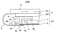
本発明としては、前記反射シートのフレキシブルプリント配線基板側先端は、当該反射シートを前記第2のフレーム部の内側壁に沿うように折り曲げることで、前記第2のフレーム部の内側壁よりも導光板側に位置するように配置されている構成としても良い。このように構成すると、反射シートの先端が、フレキシブルプリント配線基板(FPC)に接触しなくなることに加え、光源からの光の漏れを防止することができるとともに、塵埃の侵入を防止することができる。 According to the present invention, the front end of the reflective sheet on the side of the flexible printed circuit board is guided more than the inner side wall of the second frame part by bending the reflective sheet along the inner side wall of the second frame part. It is good also as a structure arrange | positioned so that it may be located in the optical plate side. If comprised in this way, in addition to the front-end | tip of a reflection sheet not contacting a flexible printed wiring board (FPC), it can prevent the leakage of the light from a light source, and can prevent the penetration | invasion of dust. .
また、本発明の液晶表示装置は、二枚の基板間に液晶層を有する液晶表示パネルと、バックライトユニットと、電子部品が実装され、前記液晶表示パネルと電気的接続を図るフレキシブル配線基板とを有する液晶表示装置であって、前記バックライトユニットは、光源の光を所定の方向に出射させる導光板と、導光板の裏面に沿うように配置される反射シートと、導光板と液晶表示パネルを固定するためのフレームとを備え、前記フレームは、導光板と略平行な方向に延伸されてなる第1のフレーム部と、第1のフレーム部の裏面から前記反射シート側へ向かって導光板と略垂直な方向に延伸されてなる第2のフレーム部とを有し、第2のフレーム部の内側には前記反射シートが配され、第2のフレーム部の外側には前記フレキシブルプリント配線基板が配され、前記反射シートのフレキシブルプリント配線基板側先端は、前記第2のフレーム部の内側壁に形成された切り欠き部に嵌合されていることを特徴とする。 Further, the liquid crystal display device of the present invention includes a liquid crystal display panel having a liquid crystal layer between two substrates, a backlight unit, a flexible wiring board on which an electronic component is mounted and which is electrically connected to the liquid crystal display panel. The backlight unit includes a light guide plate that emits light from a light source in a predetermined direction, a reflection sheet that is disposed along the back surface of the light guide plate, a light guide plate, and a liquid crystal display panel. A first frame portion that is extended in a direction substantially parallel to the light guide plate, and the light guide plate from the back surface of the first frame portion toward the reflective sheet. And a second frame portion extending in a substantially vertical direction, the reflective sheet is disposed inside the second frame portion, and the flexible print is disposed outside the second frame portion. Wiring board is disposed, a flexible printed circuit board side front end of the reflecting sheet is characterized by being fitted in the notches formed on the inner wall of the second frame portion.
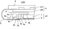
本発明によれば、前記反射シートのフレキシブルプリント配線基板側先端は、前記第2のフレーム部の内側壁に形成された切り欠き部に嵌合されていることにより、反射シートの先端が外部に露出せず、フレキシブルプリント配線基板(FPC)に接触しなくなる。これに加え、フレームに反射シートを固定する際、上記切り欠き部を位置合わせの目安にして組み立てることができる。 According to the present invention, the front end of the reflective sheet is fitted to the notch formed on the inner wall of the second frame portion so that the front end of the reflective sheet is exposed to the outside. It is not exposed and does not come into contact with the flexible printed circuit board (FPC). In addition, when the reflection sheet is fixed to the frame, the cutout portion can be used as a guide for alignment.
本発明によれば、反射シートの先端が第2のフレーム部の内側に位置するように配置されていることにより、反射シートとフレキシブルプリント配線基板(FPC)と接触することがなくなり、ショートする事態を防止することが可能になる。また、反射シートを第2のフレーム部の内側壁に沿わせる構成とすると、光源からの光の漏れを防止することができるとともに、塵埃の侵入を防止することができるため、光度が良好で、かつ、砂塵等の影響を受けにくい液晶表示装置とすることができる。また、本発明によれば、反射シートの先端を第2のフレーム部に設けられた切り欠き部に嵌合させることにより、フレキシブルプリント配線基板(FPC)と接触することがなくなり、ショートする事態を防止することができるとともに、フレームに反射シートを固定する際、上記切り欠き部を位置合わせの目安にして組み立てることができ、組み立て作業が容易となり、更に、正確な位置に反射シートを固定できる。 According to the present invention, since the tip of the reflection sheet is disposed inside the second frame portion, the reflection sheet and the flexible printed circuit board (FPC) do not come into contact with each other, and a short circuit occurs. Can be prevented. In addition, when the reflection sheet is configured to be along the inner wall of the second frame portion, light leakage from the light source can be prevented and dust can be prevented from entering, so the luminous intensity is good. And it can be set as the liquid crystal display device which is hard to be influenced by dust etc. In addition, according to the present invention, the front end of the reflection sheet is fitted into the cutout portion provided in the second frame portion, so that it does not come into contact with the flexible printed circuit board (FPC) and a short circuit occurs. It is possible to prevent this, and when fixing the reflective sheet to the frame, it is possible to assemble using the above-mentioned notched portions as a guide for alignment, facilitating assembly work, and further, fixing the reflective sheet at an accurate position.
以下、本発明の実施の形態の一例について図面を参照しながら説明する。 Hereinafter, an example of an embodiment of the present invention will be described with reference to the drawings.
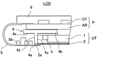
本実施の形態は、図1に示すように、携帯電話に使用される液晶表示装置LCDであり、液晶表示パネルPと、エッジライト方式の照明ユニットUTと、前記液晶表示装置LCDと前記液晶表示装置LCDが組み込まれる電子ユニット(例えば携帯電話やPDA、小型端末など)と電気的接続を図るフレキシブルプリント配線基板5を備える。前記フレキシブルプリント配線基板5は前記電子ユニットの所定の位置に固定され、前記液晶表示装置LCDと前記電子ユニットの間で電気的接続が図られるものである。なお、前記フレキシブルプリント配線基板5と前記電子ユニットの間の固定方法は今回の発明では不問のため図示していない。
As shown in FIG. 1, the present embodiment is a liquid crystal display device LCD used in a mobile phone, and includes a liquid crystal display panel P, an edge light type illumination unit UT, the liquid crystal display device LCD, and the liquid crystal display. A flexible printed
照明ユニット(バックライトユニット)UTは、照射面全体に光源(LED)hの光を伝達する平板状の透明な導光板1と、導光板1の裏面側に進行する光を反射させる反射シート2と、導光板1と反射シート2とを固定するフレーム4等を備えている。導光板1は、光伝達に必要な透過率及び屈折率で代表される光学特性が最適なアクリル等の材料で形成されている。この導光板1には、光源からの距離に応じて形状を変化させたドットパターンあるいは溝パターン(図示せず)等が裏面に施されている。
The illumination unit (backlight unit) UT includes a flat transparent
反射シート2は、導光板1の裏面から外へ出ようとする光を再度導光板1の中へ戻し出射させることにより照明光を増大させる役割を有し、導光板1の裏面に沿うように配置されている。この反射シート2は、高反射率を有する白色の樹脂製フィルムが使用され、そして、銀等の金属を蒸着した金属層を有する。このような金属層を有すると、耐食性や耐光性にも優れた高反射フィルムとなる。本実施の形態の反射シート2は、金属層を反射層として用いているが、金属層を有さずとも所望の反射機能を有する手段が含まれるものもあり(例えば反射材(非金属反射)を表面塗布したような場合であり)、このような非金属反射材料を用いた場合、電子部品との短絡の確率は格段に下がるが、本発明の構成を用いることにより前記液晶表示装置LCDの遮光性の向上や反射シートの位置決めが容易になることによる作業効率改善等の効果が見込まれるため、このような構成のものも本発明に含まれる。ただし、金属層として有するものは、フレキシブルプリント配線基板(FPC)5との接触によりショートする確率が高いことから、特に有意義である。
The
フレーム4は、液晶表示パネルPと導光板1を固定する役割を有するとともに、反射シート2を固定する役割を有し、反射シート2の一方端を固定する突出部(以下、第2のフレーム部)4aを有している。なお、上記導光板1は必ずしも上方から固定されるとは限られないが、本実施の形態では上方から固定されている。本実施の形態のフレーム4は、導光板1と略平行な方向に延伸されてなる第1のフレーム部4bと、第1のフレーム部4bの裏面4xから反射シート2側に向かって導光板1と略垂直な方向に延伸されてなる第2のフレーム部4aとを有し、前記液晶表示装置LCDを側面から透視したときに導光板1が配置される方向を内側とすれば第2のフレーム部4aの内側には反射シート2が配され、第2のフレーム部4aの外側には前記フレキシブルプリント配線基板(FPC)5が配置されている。
The
反射シート2のフレキシブルプリント配線基板5側先端2aは、第2のフレーム部4aの内側壁4yよりも導光板1側に位置するように配される。これにより、フレキシブルプリント配線基板(FPC)5のランド、配線パターンや電子部品5b等と接触することがなくなり、これらの電気的導通部とショートする事態を防止するようになっている(図1)。また、本実施の形態としては、例えば、図3に示すように、反射シート2が、第2のフレーム部4aの内側壁4yに沿うように略L字状に折り曲げられて、その先端2aが液晶表示パネルP側に向けられるようにすると良い。このような構成であっても、当該先端2aは、第2のフレーム部4aの内側壁4yよりも導光板1側に位置するように配されているため、フレキシブルプリント配線基板(FPC)5のランド、配線パターンや電子部品5a等と接触することがなくなり、これらの電気的導通部とショートする事態を防止するようになっている。これに加え、第2のフレーム部4aの外側に光源hからの光が漏れることを防止できるとともに、フレーム4の第2のフレーム部4aと導光板1との隙間Sから塵埃の侵入を防止することができ、光度が良好で、かつ、砂塵等の影響を受けにくい液晶表示装置LCDとすることができる。
The flexible printed
本実施の他の形態としては、図2に示すように、上記で説明した液晶表示装置LCD(図1、図3)とほぼ同じ構成であるが、上記第2のフレーム部4aの内側壁4yに切り欠き部4kを形成し、この切り欠き部4kに上記反射シート2のフレキシブルプリント配線基板5側先端2aを嵌合させた液晶表示装置LCDとしても良い。このように切り欠き部4kに嵌合させると、反射シート2の当該先端2aが外部に露出せず、フレキシブルプリント配線基板(FPC)5、特に電気的導通部に接触しなくなる。これに加え、フレーム4に反射シート2を固定する際、上記切り欠き部4kを位置合わせの目安にして組み立てることができ、組み立て作業が容易で、更に、正確な位置に反射シート2を固定することが可能となる。
As another embodiment of the present invention, as shown in FIG. 2, it has substantially the same configuration as the liquid crystal display device LCD (FIGS. 1 and 3) described above, but the
図1などに示すように、照明ユニットUTの照射面側(図面上は上方)に、液晶表示パネルPが搭載されるとともに、フレキシブルプリント配線基板(FPC)5が電気的に接続され、液晶表示装置LCDが組み立てられる(フレキシブルプリント配線基板(FPC)5は、この段階では、液晶表示パネルPとのみ接続され、後に前記フレキシブルプリント配線基板5は前記電子ユニットの所定の位置に固定され、前記液晶表示装置LCDと前記電子ユニットの間で電気的接続がはかられるものである。(図示せず))。
As shown in FIG. 1 and the like, a liquid crystal display panel P is mounted on the irradiation surface side (upward in the drawing) of the illumination unit UT, and a flexible printed circuit board (FPC) 5 is electrically connected to provide a liquid crystal display. The apparatus LCD is assembled (the flexible printed wiring board (FPC) 5 is connected only to the liquid crystal display panel P at this stage, and the flexible printed
本実施の形態によれば、反射シート2がフレキシブルプリント配線基板(FPC)5の電気的導通部との接触を防止する構造になっていることから、これらの接触によるショートを防止することができる。
According to the present embodiment, since the
1 導光板
2 反射シート
4 フレーム
4a フレームの突出部(第2のフレーム部)
4b 第1のフレーム部
4k 第2のフレーム部の内側壁に形成された切り欠き部
4x 第1のフレーム部の裏面
4y 第2のフレーム部の内側壁
5 フレキシブルプリント配線基板(FPC)
h 光源
LCD 液晶表示装置
P 液晶表示パネル
DESCRIPTION OF
4b
h Light source LCD Liquid crystal display device P Liquid crystal display panel
Claims (4)
前記バックライトユニットは、光源の光を所定の方向に出射させる導光板と、導光板の裏面に沿うように配置される反射シートと、導光板と液晶表示パネルを固定するためのフレームとを備え、
前記フレームは、導光板と略平行な方向に延伸されてなる第1のフレーム部と、第1のフレーム部の裏面から前記反射シート側へ向かって導光板と略垂直な方向に延伸されてなる第2のフレーム部とを有し、第2のフレーム部の内側には前記反射シートが配され、第2のフレーム部の外側には前記フレキシブルプリント配線基板が配され、
前記反射シートのフレキシブルプリント配線基板側先端は、前記第2のフレーム部の内側壁よりも導光板側に位置するように配置されていることを特徴とする
液晶表示装置。 A liquid crystal display device having a liquid crystal display panel having a liquid crystal layer between two substrates, a backlight unit, and a flexible wiring board on which electronic components are mounted and electrically connected to the liquid crystal display panel,
The backlight unit includes a light guide plate that emits light from a light source in a predetermined direction, a reflection sheet that is disposed along the back surface of the light guide plate, and a frame that fixes the light guide plate and the liquid crystal display panel. ,
The frame is extended in a direction substantially perpendicular to the light guide plate from the back surface of the first frame portion toward the reflection sheet side, with a first frame portion extended in a direction substantially parallel to the light guide plate. A second frame portion, the reflective sheet is disposed inside the second frame portion, the flexible printed wiring board is disposed outside the second frame portion,
The liquid crystal display device, wherein the tip of the reflective sheet on the side of the flexible printed wiring board is positioned so as to be positioned closer to the light guide plate than the inner wall of the second frame portion.
前記バックライトユニットは、光源の光を所定の方向に出射させる導光板と、導光板の裏面に沿うように配置される反射シートと、導光板と液晶表示パネルを固定するためのフレームとを備え、
前記フレームは、導光板と略平行な方向に延伸されてなる第1のフレーム部と、第1のフレーム部の裏面から前記反射シート側へ向かって導光板と略垂直な方向に延伸されてなる第2のフレーム部とを有し、第2のフレーム部の内側には前記反射シートが配され、第2のフレーム部の外側には前記フレキシブルプリント配線基板が配され、
前記反射シートのフレキシブルプリント配線基板側先端は、前記第2のフレーム部の内側壁に形成された切り欠き部に嵌合されていることを特徴とする液晶表示装置。 A liquid crystal display device having a liquid crystal display panel having a liquid crystal layer between two substrates, a backlight unit, and a flexible wiring board on which electronic components are mounted and electrically connected to the liquid crystal display panel,
The backlight unit includes a light guide plate that emits light from a light source in a predetermined direction, a reflection sheet that is disposed along the back surface of the light guide plate, and a frame that fixes the light guide plate and the liquid crystal display panel. ,
The frame is extended in a direction substantially perpendicular to the light guide plate from the back surface of the first frame portion toward the reflection sheet side, with a first frame portion extended in a direction substantially parallel to the light guide plate. A second frame portion, the reflective sheet is disposed inside the second frame portion, the flexible printed wiring board is disposed outside the second frame portion,
The flexible printed wiring board side front end of the reflection sheet is fitted into a notch formed on the inner wall of the second frame portion.
The liquid crystal display device according to claim 1, wherein the reflection sheet is formed by covering a resin sheet with a metal layer.
Priority Applications (1)
| Application Number | Priority Date | Filing Date | Title |
|---|---|---|---|
| JP2006103794A JP2006313331A (en) | 2005-04-07 | 2006-04-05 | Liquid crystal display device |
Applications Claiming Priority (2)
| Application Number | Priority Date | Filing Date | Title |
|---|---|---|---|
| JP2005111238 | 2005-04-07 | ||
| JP2006103794A JP2006313331A (en) | 2005-04-07 | 2006-04-05 | Liquid crystal display device |
Publications (1)
| Publication Number | Publication Date |
|---|---|
| JP2006313331A true JP2006313331A (en) | 2006-11-16 |
Family
ID=37534828
Family Applications (1)
| Application Number | Title | Priority Date | Filing Date |
|---|---|---|---|
| JP2006103794A Pending JP2006313331A (en) | 2005-04-07 | 2006-04-05 | Liquid crystal display device |
Country Status (1)
| Country | Link |
|---|---|
| JP (1) | JP2006313331A (en) |
Citations (8)
| Publication number | Priority date | Publication date | Assignee | Title |
|---|---|---|---|---|
| JPH08179321A (en) * | 1994-12-27 | 1996-07-12 | Sanyo Electric Co Ltd | Liquid crystal display |
| JPH10239686A (en) * | 1997-02-27 | 1998-09-11 | Sanyo Electric Co Ltd | Liquid crystal display |
| WO1999014630A1 (en) * | 1997-09-17 | 1999-03-25 | Hitachi, Ltd. | Liquid crystal display |
| JP2002229022A (en) * | 2001-02-02 | 2002-08-14 | Sony Corp | Liquid crystal display device and backlight device for liquid crystal display element |
| JP2003066418A (en) * | 2001-08-23 | 2003-03-05 | Seiko Epson Corp | Electro-optical devices and electronic equipment |
| JP2003167230A (en) * | 2001-11-29 | 2003-06-13 | Sharp Corp | Display device and method of manufacturing display device |
| JP2003346536A (en) * | 2002-05-28 | 2003-12-05 | Samsung Electronics Co Ltd | Backlight assembly and liquid crystal display device having the same |
| JP2005084510A (en) * | 2003-09-10 | 2005-03-31 | Seiko Epson Corp | Electro-optical device and electronic apparatus including electro-optical device |
-
2006
- 2006-04-05 JP JP2006103794A patent/JP2006313331A/en active Pending
Patent Citations (8)
| Publication number | Priority date | Publication date | Assignee | Title |
|---|---|---|---|---|
| JPH08179321A (en) * | 1994-12-27 | 1996-07-12 | Sanyo Electric Co Ltd | Liquid crystal display |
| JPH10239686A (en) * | 1997-02-27 | 1998-09-11 | Sanyo Electric Co Ltd | Liquid crystal display |
| WO1999014630A1 (en) * | 1997-09-17 | 1999-03-25 | Hitachi, Ltd. | Liquid crystal display |
| JP2002229022A (en) * | 2001-02-02 | 2002-08-14 | Sony Corp | Liquid crystal display device and backlight device for liquid crystal display element |
| JP2003066418A (en) * | 2001-08-23 | 2003-03-05 | Seiko Epson Corp | Electro-optical devices and electronic equipment |
| JP2003167230A (en) * | 2001-11-29 | 2003-06-13 | Sharp Corp | Display device and method of manufacturing display device |
| JP2003346536A (en) * | 2002-05-28 | 2003-12-05 | Samsung Electronics Co Ltd | Backlight assembly and liquid crystal display device having the same |
| JP2005084510A (en) * | 2003-09-10 | 2005-03-31 | Seiko Epson Corp | Electro-optical device and electronic apparatus including electro-optical device |
Similar Documents
| Publication | Publication Date | Title |
|---|---|---|
| JP4664757B2 (en) | Liquid crystal display device and its illumination device | |
| EP2555025B1 (en) | Liquid crystal display module | |
| CN102193227B (en) | LCD Modules and Electronics | |
| US8651721B2 (en) | Planar illumination apparatus | |
| US8212960B2 (en) | Display apparatus | |
| CN103718229A (en) | Display device | |
| US20080297689A1 (en) | Liquid crystal display device | |
| JP2015176680A (en) | surface light source device | |
| JP2005275381A (en) | Flat panel display | |
| JP4627319B2 (en) | LIGHTING DEVICE AND DISPLAY DEVICE USING THE SAME | |
| JP2009216810A (en) | Electrooptical device and electronic equipment | |
| CN103732973A (en) | Lighting device and display device provided with same | |
| JP5196565B2 (en) | Light source device and electronic device | |
| WO2017077910A1 (en) | Illumination device and display device | |
| JP2013045512A (en) | Planar light source device and display device | |
| JP4433898B2 (en) | Liquid crystal display | |
| KR101245086B1 (en) | Backlight unit and liquid crystal display device having thereof | |
| JP5410240B2 (en) | Display module and electronic device | |
| JP5013524B2 (en) | Backlight unit and liquid crystal display device | |
| KR20140070092A (en) | Printed circuit board, lighting device having the printed circuit board and back light unit having the printed circuit board | |
| JP4548124B2 (en) | LCD module | |
| JP2001330817A (en) | Liquid crystal display device and manufacturing method thereof | |
| JP4289992B2 (en) | Liquid crystal display | |
| CN218068505U (en) | Side-in type backlight module and display device | |
| JP2002182205A (en) | Liquid crystal display |
Legal Events
| Date | Code | Title | Description |
|---|---|---|---|
| A621 | Written request for application examination |
Free format text: JAPANESE INTERMEDIATE CODE: A621 Effective date: 20080421 |
|
| A977 | Report on retrieval |
Free format text: JAPANESE INTERMEDIATE CODE: A971007 Effective date: 20110201 |
|
| A131 | Notification of reasons for refusal |
Free format text: JAPANESE INTERMEDIATE CODE: A131 Effective date: 20110310 |
|
| A02 | Decision of refusal |
Free format text: JAPANESE INTERMEDIATE CODE: A02 Effective date: 20110705 |