JP2006306322A - Suspension for vehicle - Google Patents
Suspension for vehicle Download PDFInfo
- Publication number
- JP2006306322A JP2006306322A JP2005133336A JP2005133336A JP2006306322A JP 2006306322 A JP2006306322 A JP 2006306322A JP 2005133336 A JP2005133336 A JP 2005133336A JP 2005133336 A JP2005133336 A JP 2005133336A JP 2006306322 A JP2006306322 A JP 2006306322A
- Authority
- JP
- Japan
- Prior art keywords
- vehicle
- arm
- vehicle body
- holding means
- knuckle
- Prior art date
- Legal status (The legal status is an assumption and is not a legal conclusion. Google has not performed a legal analysis and makes no representation as to the accuracy of the status listed.)
- Granted
Links
Images


Classifications
-
- B—PERFORMING OPERATIONS; TRANSPORTING
- B60—VEHICLES IN GENERAL
- B60G—VEHICLE SUSPENSION ARRANGEMENTS
- B60G3/00—Resilient suspensions for a single wheel
- B60G3/18—Resilient suspensions for a single wheel with two or more pivoted arms, e.g. parallelogram
- B60G3/20—Resilient suspensions for a single wheel with two or more pivoted arms, e.g. parallelogram all arms being rigid
-
- B—PERFORMING OPERATIONS; TRANSPORTING
- B60—VEHICLES IN GENERAL
- B60G—VEHICLE SUSPENSION ARRANGEMENTS
- B60G7/00—Pivoted suspension arms; Accessories thereof
- B60G7/006—Attaching arms to sprung or unsprung part of vehicle, characterised by comprising attachment means controlled by an external actuator, e.g. a fluid or electrical motor
-
- B—PERFORMING OPERATIONS; TRANSPORTING
- B60—VEHICLES IN GENERAL
- B60G—VEHICLE SUSPENSION ARRANGEMENTS
- B60G7/00—Pivoted suspension arms; Accessories thereof
- B60G7/02—Attaching arms to sprung part of vehicle
-
- B—PERFORMING OPERATIONS; TRANSPORTING
- B60—VEHICLES IN GENERAL
- B60G—VEHICLE SUSPENSION ARRANGEMENTS
- B60G2200/00—Indexing codes relating to suspension types
- B60G2200/10—Independent suspensions
- B60G2200/14—Independent suspensions with lateral arms
- B60G2200/144—Independent suspensions with lateral arms with two lateral arms forming a parallelogram
-
- B—PERFORMING OPERATIONS; TRANSPORTING
- B60—VEHICLES IN GENERAL
- B60G—VEHICLE SUSPENSION ARRANGEMENTS
- B60G2200/00—Indexing codes relating to suspension types
- B60G2200/30—Rigid axle suspensions
- B60G2200/34—Stabilising mechanisms, e.g. for lateral stability
- B60G2200/347—Stabilising mechanisms, e.g. for lateral stability with an axle suspended by two laterally displaced rods having an imaginary point of intersection below the wheel axis
-
- B—PERFORMING OPERATIONS; TRANSPORTING
- B60—VEHICLES IN GENERAL
- B60G—VEHICLE SUSPENSION ARRANGEMENTS
- B60G2200/00—Indexing codes relating to suspension types
- B60G2200/40—Indexing codes relating to the wheels in the suspensions
- B60G2200/46—Indexing codes relating to the wheels in the suspensions camber angle
-
- B—PERFORMING OPERATIONS; TRANSPORTING
- B60—VEHICLES IN GENERAL
- B60G—VEHICLE SUSPENSION ARRANGEMENTS
- B60G2204/00—Indexing codes related to suspensions per se or to auxiliary parts
- B60G2204/10—Mounting of suspension elements
- B60G2204/14—Mounting of suspension arms
- B60G2204/143—Mounting of suspension arms on the vehicle body or chassis
-
- B—PERFORMING OPERATIONS; TRANSPORTING
- B60—VEHICLES IN GENERAL
- B60G—VEHICLE SUSPENSION ARRANGEMENTS
- B60G2204/00—Indexing codes related to suspensions per se or to auxiliary parts
- B60G2204/10—Mounting of suspension elements
- B60G2204/14—Mounting of suspension arms
- B60G2204/148—Mounting of suspension arms on the unsprung part of the vehicle, e.g. wheel knuckle or rigid axle
-
- B—PERFORMING OPERATIONS; TRANSPORTING
- B60—VEHICLES IN GENERAL
- B60G—VEHICLE SUSPENSION ARRANGEMENTS
- B60G2204/00—Indexing codes related to suspensions per se or to auxiliary parts
- B60G2204/40—Auxiliary suspension parts; Adjustment of suspensions
- B60G2204/421—Pivoted lever mechanisms for mounting suspension elements, e.g. Watt linkage
-
- B—PERFORMING OPERATIONS; TRANSPORTING
- B60—VEHICLES IN GENERAL
- B60G—VEHICLE SUSPENSION ARRANGEMENTS
- B60G2204/00—Indexing codes related to suspensions per se or to auxiliary parts
- B60G2204/40—Auxiliary suspension parts; Adjustment of suspensions
- B60G2204/422—Links for mounting suspension elements
-
- B—PERFORMING OPERATIONS; TRANSPORTING
- B60—VEHICLES IN GENERAL
- B60G—VEHICLE SUSPENSION ARRANGEMENTS
- B60G2204/00—Indexing codes related to suspensions per se or to auxiliary parts
- B60G2204/40—Auxiliary suspension parts; Adjustment of suspensions
- B60G2204/423—Rails, tubes, or the like, for guiding the movement of suspension elements
- B60G2204/4232—Sliding mounts
Abstract
Description
本発明は、アッパアーム及びロアアームにてナックルを揺動可能に保持する車両用サスペンション装置に関するものである。 The present invention relates to a vehicle suspension apparatus that holds a knuckle swingably with an upper arm and a lower arm.
車両用サスペンション装置には、ダブルウィッシュボーン式のようにアッパアーム及びロアアームにてナックルを揺動可能に保持するものが各種知られている(例えば、特許文献1参照)。
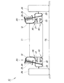
特許文献1に示す従来の車両用サスペンション装置を、次の図16に基づいて説明する。図16は従来の車両用サスペンション装置の概念図であり、後方から見た車両200及び右の車両用サスペンション装置210を示す。
A conventional vehicle suspension device shown in Patent Document 1 will be described with reference to FIG. FIG. 16 is a conceptual diagram of a conventional vehicle suspension apparatus, and shows a
従来の車両用サスペンション装置210は、車体201の側部に上下揺動可能に連結した上側のアッパアーム211並びに下側のロアアーム212と、これらアッパ・ロアアーム211,212の先端部に連結したナックル213とを主要構成として、車体201に車輪214を懸架する、ダブルウィッシュボーン式サスペンションである。
A conventional
ところで、車両200を左へ旋回させたときには、旋回中の車両200に遠心力がかかるので、左右の車輪214を懸架する車両用サスペンション装置210のうち、旋回外側のダンパやバネは縮み、旋回内側のダンパやバネは伸びる。この結果、車体201は旋回外側(右側)が沈み込むとともに旋回内側が持ち上がるように傾く、いわゆるロール運動をする。この場合、右の車輪214が旋回外輪となる。
このロール運動は、サスペンションリンク(アーム)の配置によって幾何学的に決定される、ロールセンタRC2を中心とした、車体201の回転運動であるといわれている。
By the way, when the
This roll motion is said to be a rotational motion of the
図16に示すように、路面GLに対する右の車輪214の接地点はPg2であり、路面GLからロールセンタRC2までの高さ(ロール高さ)はHr2であり、接地点Pg2とロールセンタRC2とを通る線はLi2であり、路面GLに対する線Li2の傾斜角はθ2である。
As shown in FIG. 16, the contact point of the
車体201に対して車輪214が上向きに揺動する際に、車輪214の接地点Pg2が車幅方向の外側へ張り出す。従って、接地点Pg2の旋回軌跡Lg2は、車幅方向の外側に且つ上方に延びる曲線となる。この結果、ロール高さHr2は比較的大きい。
When the
接地点Pg2で車輪214に対してコーナリングフォースCF2(横力CF2)が生じたときに、車輪214には、傾斜角θ2に応じて、ロールセンタRC2に向かう分力Fs2(水平分力Fs2と言う)と、路面GLに向かう分力Fg2(垂直分力Fg2と言う)とが働く。水平分力Fs2は、車両用サスペンション装置210が受け止める横力であり、垂直分力Fg2は、車輪214を持ち上げようとするジャッキアップ力である。この垂直分力Fg2は、概ね次の式で求めることができる。
Fg2=CF2×sinθ2
傾斜角θ2が比較的大きいので、垂直分力Fg2も大きくなる。このため、車輪214の持ち上がり現象を抑制することが求められている。
When a cornering force CF2 (lateral force CF2) is generated on the
Fg2 = CF2 × sin θ2
Since the inclination angle θ2 is relatively large, the vertical component force Fg2 also increases. For this reason, it is required to suppress the lifting phenomenon of the
さらには、路面GLに対して車輪214のタイヤができるだけ垂直になるように、サスペンションのアライメント面が考えられてきた。
つまり、車体201に対して車両用サスペンション装置210が上にストロークしたとき、すなわちバンプしたときのキャンバ(ストローク・キャンバ)の特性を、ネガティブキャンバ角が増大するように考えられてきた。
Furthermore, the alignment surface of the suspension has been considered so that the tire of the
That is, it has been considered that the negative camber angle increases the characteristics of the camber (stroke camber) when the
しかし、ダブルウイッシュボーン式やストラット式でリンクの配置を工夫してストローク・キャンバにネガティブキャンバ角を設けると、ロール高さHr2が大きくなる。この結果、大きいジャッキアップ力Fg2が働く。
このため、タイヤの接地面圧が、旋回外輪で急増するとともに旋回内輪で急減することにより、旋回外輪への分担荷重の移動が急激になる。旋回内・外輪のタイヤグリップの総和は、タイヤの飽和特性によって急激に低下してしまう。従って、最適なグリップ力を向上させることが容易でない。また、旋回時における車両用サスペンション装置210の緩衝機能を向上させることが容易でない。
However, if a link camber is devised by a double wishbone type or a strut type to provide a negative camber angle to the stroke camber, the roll height Hr2 increases. As a result, a large jackup force Fg2 works.
For this reason, the ground contact surface pressure of the tire suddenly increases at the turning outer wheel and rapidly decreases at the turning inner wheel, so that the shared load moves to the turning outer wheel suddenly. The sum of the tire grips on the inner and outer wheels of the turn is drastically reduced due to the saturation characteristics of the tire. Therefore, it is not easy to improve the optimum grip force. Further, it is not easy to improve the buffer function of the
これは、車両用サスペンション装置210が上にストロークしたときに、アッパアーム211やストラットでタイヤの上部を車幅方向の内側に引き込み、ロアアーム212でタイヤの中央よりやや下部を保持、又は外側に押し出す結果、車輪214の接地点Pg2が車幅方向の外側に押し出されて、上広がりの軌跡を描いてストロークすることに起因している。
This is because when the
本発明は、(1)車輪を路面に効率良く接地させるための大きなキャンバ変化と、(2)旋回時の内外輪の荷重移動量を支配するロールセンタの高さとを、同時に適正化することができる技術を提供することを課題とする。 According to the present invention, (1) a large camber change for efficiently grounding the wheel to the road surface and (2) the height of the roll center that governs the load movement amount of the inner and outer wheels during turning can be optimized simultaneously. It is an object to provide a technology that can be used.
請求項1に係る発明は、車輪を回転可能に保持するナックルと、車体に対して揺動可能に連結されナックルの上部を保持するアッパアームと、車体に対して揺動可能に連結されナックルの下部を保持するロアアームと、を備えた車両用サスペンション装置において、この車両用サスペンション装置に、アッパ・ロアアームをそれぞれ車幅方向へ移動可能に保持する保持手段と、アッパ・ロアアームの上下方向の揺動を車幅方向への変位に変換する変換手段とを備えたことを特徴とする。 The invention according to claim 1 includes a knuckle that rotatably holds a wheel, an upper arm that is swingably connected to the vehicle body and holds an upper portion of the knuckle, and a lower portion of the knuckle that is swingably connected to the vehicle body. And a lower arm that holds the upper and lower arms in the vehicle suspension device, and the upper and lower arms swing in the vertical direction. Conversion means for converting to displacement in the vehicle width direction.
請求項2に係る発明は、請求項1において、変換手段が、アッパ・ロアアームの少なくとも一方における車体側の端部を、車体に連結するキャンバコントロールアームからなり、このキャンバコントロールアームが、アッパ・ロアアームの上下方向の揺動に応じて、端部を車体側へ引き込む方向に揺動するように構成したことを特徴とする。 According to a second aspect of the present invention, in the first aspect, the conversion means includes a camber control arm that connects at least one of the upper and lower arms on the vehicle body side to the vehicle body, and the camber control arm includes the upper and lower arms. It is characterized in that it is configured to swing in the direction in which the end portion is pulled in to the vehicle body side in accordance with the vertical swing of.
請求項3に係る発明は、請求項1又は請求項2において、保持手段を、係合凸部と、この係合凸部を車幅方向へ相対的に移動可能に保持する長孔とで構成し、係合凸部を、アッパ・ロアアームの少なくとも一方における中間部又は車体に設けるとともに、長孔を、車体又は中間部に設けたことを特徴とする。 According to a third aspect of the present invention, in the first or second aspect, the holding means includes an engaging convex portion and a long hole that holds the engaging convex portion so as to be relatively movable in the vehicle width direction. The engaging convex portion is provided in the intermediate portion or the vehicle body in at least one of the upper and lower arms, and the long hole is provided in the vehicle body or the intermediate portion.
請求項4に係る発明は、請求項1又は請求項2において、保持手段が、アッパ・ロアアームの少なくとも一方における中間部を、車体に連結するスイングアームからなり、このスイングアームが、アッパ・ロアアームの上下方向の揺動に応じて、中間部を車幅方向へ移動可能に保持する方向に揺動するように構成したことを特徴とする。 According to a fourth aspect of the present invention, in the first or second aspect, the holding means includes a swing arm that connects at least one of the intermediate portions of the upper and lower arms to the vehicle body, and the swing arm includes the upper and lower arms. According to the vertical swing, the intermediate portion is configured to swing in a direction to be held movably in the vehicle width direction.
請求項5に係る発明は、請求項1において、保持手段が、アッパアーム又はロアアームにおける、中間部を保持するとともに、アーム長手方向にのみ弾性変形が可能な第1ラバー部からなり、変換手段が、アッパアーム又はロアアームにおける、車体側の端部を保持するとともに、車幅方向にのみ弾性変形が可能な第2ラバー部からなり、これら第1・第2ラバー部が、互いに一体に形成した部材であることを特徴とする。 The invention according to claim 5 comprises the first rubber part according to claim 1, wherein the holding means holds the intermediate part of the upper arm or the lower arm and can be elastically deformed only in the longitudinal direction of the arm. The upper arm or the lower arm includes a second rubber portion that holds the end portion on the vehicle body side and can be elastically deformed only in the vehicle width direction, and the first and second rubber portions are members formed integrally with each other. It is characterized by that.
請求項1に係る発明では、下の保持手段によって、ロアアームを車幅方向へ移動可能に保持するとともに、下の変換手段によって、ロアアームを車体側へ引き込むようにしたものである。
このため、車体に対して車輪が上向きに揺動する際に、車輪の接地点が車幅方向の外側へ張り出すのを、抑制することができる。従って、接地点の旋回軌跡は、ほぼ鉛直な上向き方向に延びる曲線となる。つまり、車輪は接地点のほぼ真上に揺動することになる。この結果、路面からロールセンタまでの高さ(ロール高さ)を下げることができる。
In the first aspect of the invention, the lower arm is held by the lower holding means so as to be movable in the vehicle width direction, and the lower arm is pulled into the vehicle body by the lower conversion means.
For this reason, when the wheel swings upward with respect to the vehicle body, it is possible to suppress the contact point of the wheel from protruding outward in the vehicle width direction. Therefore, the turning locus of the ground contact point is a curve extending in a substantially vertical upward direction. That is, the wheel swings almost directly above the grounding point. As a result, the height from the road surface to the roll center (roll height) can be lowered.
さらに請求項1に係る発明では、上の保持手段によって、アッパアームを車幅方向へ移動可能に保持するとともに、上の変換手段によって、アッパアームを車体側へ引き込むようにしたものである。
このように、アッパ・ロアアームの両方を車体側へ引き込むように構成したものであるから、アッパアームが車体側へ引き込まれる量に対し、ロアアームが引き込まれる量を、適宜小さく設定することができる。従って、車両の旋回走行中(コーナリング走行中)における、旋回外側の車輪のキャンバ角をネガティブ側に変化させることができる。このため、旋回外側の車輪のキャンバを、路面に対してほぼ垂直に保持、又は、旋回内側に内傾させる(ネガティブ側に変化させる)ことができる。
Furthermore, in the invention according to claim 1, the upper arm is held so as to be movable in the vehicle width direction by the upper holding means, and the upper arm is drawn into the vehicle body side by the upper conversion means.
Thus, since both the upper and lower arms are configured to be retracted toward the vehicle body side, the amount by which the lower arm is retracted can be appropriately set smaller than the amount by which the upper arm is retracted toward the vehicle body side. Accordingly, it is possible to change the camber angle of the wheel on the outer side of the turn to the negative side during turning of the vehicle (during cornering). For this reason, the camber of the wheel on the outside of the turn can be held substantially perpendicular to the road surface, or can be tilted inward (changed to the negative side) inside the turn.
このように、請求項1に係る発明では、簡単な構成によって、(1)車輪を路面に効率良く接地させるための大きなキャンバ変化と、(2)旋回時の内外輪の荷重移動量を支配するロールセンタの高さとを、同時に適正化することができる。従って、車両の高い運動性能並びに走行安定性を得ることができるとともに、車輪におけるタイヤの摩耗を低減させることができる。 As described above, in the invention according to claim 1, with a simple configuration, (1) a large camber change for efficiently grounding the wheel to the road surface, and (2) a load movement amount of the inner and outer wheels during turning are controlled. The height of the roll center can be optimized at the same time. Therefore, it is possible to obtain high vehicle performance and running stability, and to reduce tire wear on the wheels.
つまり、車両の旋回時におけるタイヤの接地面を路面に均一に当てることができる。このため、
(11)旋回中のタイヤ性能をより限界まで引き出し、車両の走行安定性や操縦性能を高めることができ、緊急時の回避の能力を高めることができる。
(12)従来両立が困難であった、ロールセンタの高さを下げることと、大きいキャンバ特性を得ることとを、同時に改良できるため、旋回初期のタイヤの荷重移動による負荷を低減して、安定した旋回過渡特性を得て、緊急時の回避の能力を高めることができる。
(13)旋回制動時における、車両の制動距離を短縮することができるので、衝突を容易に回避することができる。
(14)旋回時には、タイヤが路面に偏当たりをすることで、タイヤの摩耗を促進させるものであるが、このような偏当たりを抑制することができる。この結果、タイヤの使用寿命を延ばすことができ、省資源化にも貢献することができる。
In other words, the tire contact surface can be uniformly applied to the road surface when the vehicle is turning. For this reason,
(11) The tire performance during turning can be pulled to the limit, and the running stability and steering performance of the vehicle can be enhanced, and the avoidance capability in an emergency can be enhanced.
(12) Lowering the height of the roll center and obtaining a large camber characteristic, which were difficult to achieve at the same time, can be improved at the same time. It is possible to improve the ability to avoid emergency in the event of turning transient characteristics.
(13) Since the braking distance of the vehicle at the time of turning braking can be shortened, a collision can be easily avoided.
(14) During turning, the tire is biased against the road surface to promote wear of the tire, but such a bias can be suppressed. As a result, it is possible to extend the service life of the tire and contribute to resource saving.
さらに請求項1に係る発明では、短いアッパ・ロアアームの曲率のきつい揺動軌跡を、緩やかにコントロールする目的にも適用することができる。このため、より小型(省スペース、軽量)なサスペンション装置を構築することができ、同一寸法で車両に、より広い居住空間、荷室空間を設けることができる。また、スペースに余裕のない小型車のサスペンション性能に、上記第(11)項〜第(14)項の効果をもたらすことができる。 Furthermore, the invention according to claim 1 can be applied to the purpose of gently controlling the tight swing locus of the curvature of the short upper and lower arms. For this reason, a smaller (space-saving, lightweight) suspension device can be constructed, and a wider living space and cargo space can be provided in the vehicle with the same dimensions. Moreover, the effect of said (11) term-(14) term can be brought about on the suspension performance of the small vehicle which has no space.
請求項2に係る発明では、変換手段をキャンバコントロールアームにて構成したので、簡単な構成によって、アッパ・ロアアームの端部を車体側へ引き込むことができる。 In the invention according to claim 2, since the conversion means is constituted by the camber control arm, the end portions of the upper and lower arms can be pulled into the vehicle body side with a simple configuration.
請求項3に係る発明では、保持手段を、係合凸部と長孔との組合せにて構成したので、簡単な構成によって、アッパ・ロアアームを保持することができる。 In the invention according to claim 3, since the holding means is configured by a combination of the engaging convex portion and the long hole, the upper and lower arms can be held with a simple configuration.
請求項4に係る発明では、保持手段をスイングアームにて構成したので、簡単な構成によって、アッパ・ロアアームを保持することができる。 In the invention according to claim 4, since the holding means is constituted by the swing arm, the upper and lower arms can be held by a simple configuration.
請求項5に係る発明では、弾性変形が可能な第1・第2ラバー部を互いに一体に形成することにより、保持手段及び変換手段を一体に構成したので、部品数が少なく簡単な構成にすることができる。しかも、保持手段及び変換手段を一体に構成したので、車体に保持手段及び変換手段を容易に組付けることができる。 In the invention according to claim 5, the first and second rubber portions that can be elastically deformed are integrally formed with each other, so that the holding means and the conversion means are integrally formed, so that the number of parts is reduced and the structure is simplified. be able to. Moreover, since the holding means and the conversion means are integrally formed, the holding means and the conversion means can be easily assembled to the vehicle body.
本発明を実施するための最良の形態を添付図に基づいて以下に説明する。先ず、車両用サスペンション装置の第1実施例について、図1〜図5に基づき説明する。 The best mode for carrying out the present invention will be described below with reference to the accompanying drawings. First, a first embodiment of a vehicle suspension apparatus will be described with reference to FIGS.
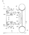
図1は本発明に係る車両用サスペンション装置(第1実施例)の概念図であり、後方から見た車両及び左右の車両用サスペンション装置を示す。車両10における車体11(サブフレームを含む)は、上部に左右のダンパハウジング12,12を取付けるとともに、側部に独立懸架する左右の車両用サスペンション装置20,20を取付けたものである。
FIG. 1 is a conceptual diagram of a vehicle suspension device (first embodiment) according to the present invention, and shows a vehicle and left and right vehicle suspension devices viewed from the rear. A vehicle body 11 (including a sub-frame) in the
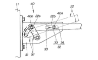
図2は本発明に係る右の車両用サスペンション装置(第1実施例)の概念図であり、図1に対応させて表した。
図1及び図2に示すように、右の車両用サスペンション装置20は、車体11の側部に上下揺動可能に連結した上側のアッパアーム21並びに下側のロアアーム22と、これらアッパ・ロアアーム21,22の先端部に連結したナックル23と、ダンパハウジング12とロアアーム22との間に取付けたダンパ24並びにコイルばね25とを主要構成として、車体11に車輪26を懸架する、ダブルウィッシュボーン式サスペンションである。
FIG. 2 is a conceptual diagram of the right vehicle suspension device (first embodiment) according to the present invention, and is shown corresponding to FIG.
As shown in FIGS. 1 and 2, the right
アッパアーム21は、その基端部21a(車体11側の端部21a)を車体11に上部連結部30にて連結するとともに、先端部にナックル23の上部を保持するスイング部材である。ロアアーム22は、その基端部22a(車体11側の端部22a)を車体11に下部連結部40にて連結するとともに、先端部にナックル23の下部を保持するスイング部材である。ナックル23は、車輪26を回転可能に保持する部材である。
The
なお、左の車両用サスペンション装置20は、右の車両用サスペンション装置20と左右対称である他には同様の構成であり、同一符号を付し、その説明を省略する。
このような左右の車両用サスペンション装置20,20は、フロントサスペンション又はリヤサスペンションとして採用することができる。
The left
Such left and right
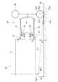
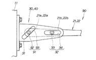
図3は本発明に係る保持手段及び変換手段(第1実施例)の構成図であり、図2に対応させて表した。図2及び図3に示すように、上部連結部30は、車体11に取付けたブラケット31と、ブラケット31に設けた保持手段32及び変換手段37とからなる。保持手段32は、アッパアーム21を車幅方向(図の左右方向)へ移動可能に保持する機構である。変換手段37は、アッパアーム21の上下方向の揺動を車幅方向への変位に変換する機構である。
このように上部連結部30は、ブラケット31に保持手段32及び変換手段37を一体的に組付けたユニットとしたので、車体11に保持手段32及び変換手段37を容易に組付けることができる。
FIG. 3 is a block diagram of the holding means and the conversion means (first embodiment) according to the present invention, and is shown corresponding to FIG. As shown in FIGS. 2 and 3, the upper connecting
As described above, the upper connecting
より詳しく説明すると、図3に示すように、保持手段32は係合凸部33と、この係合凸部33を車幅方向へ相対的に移動可能に保持する長孔34とからなる。
係合凸部33は、アッパアーム21の基端部21aのうち、車幅方向の中間寄りの位置(以下、中間部21bと言う。)に設けた部材であり、例えば中間部21bの側面に回転可能に取付けたローラからなる。長孔34は、ブラケット31の側面(すなわち、車体11側)に設けたものであり、車幅方向にほぼ水平に延びる。
なお、保持手段32は、係合凸部33をブラケット31に設けるとともに、長孔34をアッパアーム21の中間部21bに設けた構成であってもよい。
More specifically, as shown in FIG. 3, the holding means 32 includes an engaging
The engagement
The holding means 32 may have a configuration in which the engaging
図3に示すように、変換手段37は、アッパアーム21の基端部21aを、車体11に連結するキャンバコントロールアームからなる。
より具体的には、キャンバコントロールアーム37(すなわち、変換手段37)は、アッパアーム21の上下方向の揺動に応じて、アッパアーム21の基端部21aを車体11側へ引き込む方向に、揺動するように構成したものである。つまり、キャンバコントロールアーム37は、その基端部をブラケット31の側面(すなわち、車体11側)に、車幅方向への揺動可能に連結するとともに、アームを下方へ延ばし、その先端部をアッパアーム21の基端部21aに連結した構成である。なお、アッパアーム21とキャンバコントロールアーム37とは、互いに揺動可能に連結することになる。
As shown in FIG. 3, the conversion means 37 includes a camber control arm that connects the
More specifically, the camber control arm 37 (that is, the conversion means 37) swings in the direction in which the
なお、上部連結部30は、保持手段32における係合凸部33と長孔34との連結点30a(上の保持手段連結点30a)に対して、キャンバコントロールアーム37の先端部とアッパアーム21の基端部21aとの連結点30b(上の変換手段連結点30b)を高位に配置したものである。
The upper connecting
図2及び図3に示すように、下部連結部40は、上部連結部30と基本的に同様の構成である。詳しくは、下部連結部40は、ロアアーム22を車幅方向へ移動可能に保持する保持手段32と、ロアアーム22の上下方向の揺動を車幅方向への変位に変換する変換手段37とを備える。
なお、下部連結部40は、保持手段32における係合凸部33と長孔34との連結点40a(下の保持手段連結点40a)に対して、キャンバコントロールアーム37の先端部とロアアーム22の基端部22aとの連結点40b(下の変換手段連結点40b)を低位に配置したものである。
As shown in FIGS. 2 and 3, the lower connecting
In addition, the lower connecting
このように下部連結部40は、ブラケット31に保持手段32及び変換手段37を一体的に組付けたユニットとしたので、車体11に保持手段32及び変換手段37を容易に組付けることができる。
Thus, since the lower connecting
ここで、図2において、アッパアーム21の先端部21cとナックル23の上部との連結点30cのことを、上のナックル連結点30cと言い、ロアアーム22の先端部22cとナックル23の下部との連結点40cのことを、下のナックル連結点40cと言うことにする。上のナックル連結点30cは上の保持手段連結点30aよりも高位に配置し、下のナックル連結点40cは下の保持手段連結点40aよりも低位に配置したものである。
Here, in FIG. 2, the connecting
なお、上の保持手段連結点30aに対する上の変換手段連結点30b並びに上のナックル連結点30cの高さ、及び、下の保持手段連結点40aに対する下の変換手段連結点40b並びに下のナックル連結点40cの高さについては、最適条件となるように適宜設定すればよい。
The upper conversion means
また、上部連結部30と下部連結部40とは、それぞれの部材の寸法が互いに同一又はほぼ同一である。車体11が定常状態(走行停止状態)であるときに、アッパ・ロアアーム21,22は、例えば水平又はほぼ水平状態となるように設定される。
In addition, the upper connecting
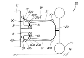
図4は本発明に係る右の車両用サスペンション装置(第1実施例)の作用図であり、図2に対応させて表した。
図4において、車体11が定常状態(走行停止状態)であるときの、車両用サスペンション装置20を想像線にて示す。この想像線の状態は図2に示すものと同様である。路面GLに対する車輪26の接地点はPg1である。
FIG. 4 is an operation diagram of the right vehicle suspension apparatus according to the present invention (first embodiment), and is shown corresponding to FIG.
In FIG. 4, the
その後、例えば車両10を旋回させる等により、車体11に対して車輪26が上向きに揺動する際に、アッパ・ロアアーム21,22は、図4の実線で示すように、それぞれ保持手段連結点30a,40aを中心に上方へ揺動しようとする。
このとき、上下のキャンバコントロールアーム37,37は、アッパ・ロアアーム21,22の上方向の揺動に応じて、図時計回りに揺動する。このため、変換手段連結点30b,40b(すなわち、アッパ・ロアアーム21,22の端部)は、車体11側へ引き込まれる。
Thereafter, when the
At this time, the upper and lower
同時に、保持手段連結点30a,40a(すなわち、アッパ・ロアアーム21,22の中間部)は車体11側へ水平に移動する。つまり、アッパ・ロアアーム21,22の揺動中心30a,40aは、車体11側へ水平に変位する。揺動中心30a,40aが車体11側へ変位した分だけ、ナックル連結点30c,40cが車体11側へ変位する変位量は、大きくなる。
At the same time, the holding means
ところで、上のナックル連結点30cは、保持手段連結点30aよりも高位に配置されている。仮に、保持手段連結点30aが変位しないと考えた場合、アッパアーム21が上方へ揺動したときに、上のナックル連結点30cが車体11側へ変位する変位量は、大きい。しかも、実際には、上のキャンバコントロールアーム37によって、上のナックル連結点30cは車体11側へ引き込まれる。この結果、上のナックル連結点30cが車体11側へ変位する変位量は、一層大きくなる。
By the way, the upper
一方、下のナックル連結点40cは、下の保持手段連結点40aよりも低位に配置されている。仮に、保持手段連結点40aが変位しないと考えた場合、ロアアーム22が上方へ揺動したときに、下のナックル連結点40cは車幅方向の外側へ若干変位する。
しかし、実際には、下のキャンバコントロールアーム37によって、下のナックル連結点40cは車体11側へ引き込まれる。この結果、下のナックル連結点40cは車体11側へ変位する。その変位量は小さい。つまり、上のナックル連結点30cが引き込まれる量に対して、下のナックル連結点40cが引き込まれる量は、極めて小さい。
On the other hand, the lower
However, actually, the lower
このようなことから、車輪26の接地点Pg1の変位量は、車輪26の上端の変位量よりも小さい。この結果、車輪26はネガティブキャンバとなるように、キャンバ角αが変化する。従って、車両10を旋回させたときに、旋回外側の車輪26のキャンバ角αをネガティブ側に変化させることができる。
For this reason, the displacement amount of the ground contact point Pg <b> 1 of the
以上の説明をまとめると、次の通りである。
車両用サスペンション装置20は、下の保持手段32によって、ロアアーム22を車幅方向へ移動可能に保持するとともに、下のキャンバコントロールアーム37によって、ロアアーム22を車体11側へ引き込むようにしたものである。
このため、車体11に対して車輪26が上向きに揺動する際に、車輪26の接地点Pg1が車幅方向の外側へ張り出すのを、抑制することができる。従って、接地点Pg1の旋回軌跡Lg1は、ほぼ鉛直な上向き方向に延びる曲線となる。つまり、車輪26は接地点Pg1のほぼ真上に揺動することになる。この結果、路面GLからロールセンタまでの高さ(ロール高さ)を下げることができる。
The above description is summarized as follows.
The
For this reason, when the
さらに車両用サスペンション装置20は、上の保持手段32によって、アッパアーム21を車幅方向へ移動可能に保持するとともに、上のキャンバコントロールアーム37によって、アッパアーム21を車体11側へ引き込むようにしたものである。
このように、アッパ・ロアアーム21,22の両方を車体11側へ引き込むように構成したものであるから、車両用サスペンション装置20の設計段階において、上のナックル連結点30cが車体11側へ引き込まれる量に対し、下のナックル連結点40cが引き込まれる量を、適宜小さく設定することができる。従って、車両10の旋回走行中(コーナリング走行中)における、旋回外側の車輪26のキャンバ角αをネガティブ側に変化させることができる。
Further, the
Thus, since both the upper and
図5は本発明に係る右の車両用サスペンション装置(第1実施例)の作用図である。
路面GLからロールセンタRC1までの高さ(ロール高さ)はHr1であり、接地点Pg1とロールセンタRC1とを通る線はLi1であり、路面GLに対する線Li1の傾斜角はθ1である。
FIG. 5 is an operation diagram of the right vehicle suspension apparatus (first embodiment) according to the present invention.
The height (roll height) from the road surface GL to the roll center RC1 is Hr1, the line passing through the contact point Pg1 and the roll center RC1 is Li1, and the inclination angle of the line Li1 with respect to the road surface GL is θ1.
車体11に対して車輪26が上向きに揺動したときに、接地点Pg1はロールセンタRC1を中心とした旋回軌跡Lg1上を、旋回する。上述のように、車輪26は接地点Pg1のほぼ真上に揺動する。この結果、ロール高さHr1を下げることができる。ロール高さHr1が下がることで、傾斜角θ1も下がる。
When the
接地点Pg1で、車輪26に対してコーナリングフォースCF1が作用したときに、車輪26には、傾斜角θ1に応じて、ロールセンタRC1に向かう分力Fs1(水平分力Fs1と言う)と、路面GLに向かう分力Fg1(垂直分力Fg1と言う)とが働く。水平分力Fs1は、車両用サスペンション装置20が受け止める横力であり、垂直分力Fg1は、車輪26を持ち上げようとするジャッキアップ力である。
When the cornering force CF1 acts on the
この垂直分力Fg1は、概ね次式(1)で求めることができる。
Fg1=CF1×sinθ1 ・・・ (1)
傾斜角θ1が小さいので、垂直分力Fg1も小さくなる。この結果、車輪26の持ち上がり現象を抑制することで、車体11の持ち上がり現象を抑制することができる。
The vertical component force Fg1 can be obtained approximately by the following equation (1).
Fg1 = CF1 × sin θ1 (1)
Since the inclination angle θ1 is small, the vertical component force Fg1 is also small. As a result, the lifting phenomenon of the
さらに、車輪26の半径をRt、ロール高さをHr1、車輪26の持ち上がり量(持ち上がりストローク)をStとしたときに、図4に示すキャンバ角αは次式(2)で求めることができる。
α=sin−1(2×St×Hr1/Rt) ・・・ (2)
Further, when the radius of the
α = sin −1 (2 × St × Hr1 / Rt) (2)
従って、キャンバ角αを適宜設定することで、車両10の旋回走行中における、旋回外側のタイヤ等の車輪26のキャンバを、路面GLに対してほぼ垂直に保持、又は、旋回内側に内傾させる(ネガティブ側に変化させる)ことができる。
Accordingly, by appropriately setting the camber angle α, the camber of the
次に、第2実施例〜第8実施例の車両用サスペンション装置について説明する。なお、上記図1〜図5に示す第1実施例の車両用サスペンション装置と同様の構成については、同一符号を付し、その説明を省略する。 Next, vehicle suspension devices according to second to eighth embodiments will be described. In addition, about the structure similar to the suspension apparatus for vehicles of 1st Example shown in the said FIGS. 1-5, the same code | symbol is attached | subjected and the description is abbreviate | omitted.
第2実施例の車両用サスペンション装置について、図6及び図7に基づき説明する。図6は本発明に係る右の車両用サスペンション装置(第2実施例)の概念図であり、図2に対応させて表した。図7は本発明に係る上部連結部(第2実施例)の構成図であり、図6に対応させて表した。 A vehicle suspension apparatus according to a second embodiment will be described with reference to FIGS. FIG. 6 is a conceptual diagram of the right vehicle suspension device (second embodiment) according to the present invention, and is shown corresponding to FIG. FIG. 7 is a configuration diagram of the upper connecting portion (second embodiment) according to the present invention, and is shown corresponding to FIG.
図6及び図7に示すように、第2実施例の車両用サスペンション装置50は、上下の保持手段51,51を変更したものである。すなわち、上下の保持手段51,51は、アッパ・ロアアーム21,22における中間部21b,22bを車体11に連結するスイングアームからなることを特徴とする。これらのスイングアーム51,51(上下の保持手段51,51)は、アッパ・ロアアーム21,22の上下方向の揺動に応じて、中間部21b,22bを車幅方向へ移動可能に保持する方向に揺動するように構成したものである。
As shown in FIGS. 6 and 7, the
より具体的には、上のスイングアーム51は、その基端部をブラケット31の側面に、車幅方向への揺動可能に連結するとともに、アームを上方へ延ばし、その先端部をアッパアーム21の中間部21bに連結した構成である。なお、アッパアーム21とスイングアーム51とは、互いに揺動可能に連結することになる。上のスイングアーム51の先端部とアッパアーム21の中間部21bとの連結点は、上の保持手段連結点30aである。
一方、下のスイングアーム51は、上のスイングアーム51と上下対称となる構成である他には同様の構成である。下のスイングアーム51の先端部とロアアーム22の中間部22bとの連結点は、下の保持手段連結点40aである。
More specifically, the
On the other hand, the
このような第2実施例の車両用サスペンション装置50は、上記第1実施例の車両用サスペンション装置20と同様の作用をなす。
さらには、上部・下部連結部30,40は、ブラケット31に保持手段51及び変換手段37を一体的に組付けたユニットとしたので、車体11に保持手段51及び変換手段37を容易に組付けることができる。
The
Furthermore, since the upper / lower connecting
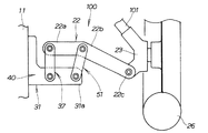
次に、第3実施例の車両用サスペンション装置について、図8〜図10に基づき説明する。図8は本発明に係る右の車両用サスペンション装置(第3実施例)の概念図であり、図2に対応させて表した。図9は本発明に係る上部連結部(第3実施例)の構成図であり、図8に対応させて表した。図10は本発明に係る下部連結部(第3実施例)の構成図であり、図8に対応させて表した。 Next, a vehicle suspension apparatus according to a third embodiment will be described with reference to FIGS. FIG. 8 is a conceptual diagram of the right vehicle suspension apparatus (third embodiment) according to the present invention, and is shown corresponding to FIG. FIG. 9 is a configuration diagram of the upper connecting portion (third embodiment) according to the present invention, and is shown corresponding to FIG. FIG. 10 is a configuration diagram of a lower connecting portion (third embodiment) according to the present invention, and is shown corresponding to FIG.
図8及び図9に示すように、第3実施例の車両用サスペンション装置60は、上部連結部30における保持手段51をスイングアームにて構成するとともに、上部連結部30における変換手段37をキャンバコントロールアームにて構成したことを特徴とする。
As shown in FIGS. 8 and 9, in the
スイングアーム51(すなわち、保持手段51)は、上記図7に示す第2実施例の保持手段51と同様の構成である。
キャンバコントロールアーム37(すなわち、変換手段37)は、上記図7に示す第2実施例の変換手段37と基本的に同様の構成であり、基端部をブラケット31の側面に、車幅方向への揺動可能に連結するとともに、アームを上方へ延ばし、その先端部をアッパアーム21の基端部21aに連結した構成である。
The swing arm 51 (that is, the holding means 51) has the same configuration as the holding means 51 of the second embodiment shown in FIG.
The camber control arm 37 (that is, the conversion means 37) has basically the same configuration as the conversion means 37 of the second embodiment shown in FIG. 7, and has a base end portion on the side surface of the
図8及び図10に示すように、さらに第3実施例の車両用サスペンション装置60は、下部連結部40における保持手段32をスライド式にするとともに、下部連結部40における変換手段37をキャンバコントロールアームにて構成したことを特徴とする。
すなわち、保持手段32は、上記図3に示す第1実施例の保持手段32と同様の構成である。キャンバコントロールアーム37は、上記図9に示す変換手段37と基本的に同様の構成である。
As shown in FIGS. 8 and 10, the
That is, the holding means 32 has the same configuration as the holding means 32 of the first embodiment shown in FIG. The
このような第3実施例の車両用サスペンション装置60は、上記第1実施例の車両用サスペンション装置20と同様の作用をなす。
さらには、上部・下部連結部30,40は、ブラケット31に保持手段32,51及び変換手段37,37を一体的に組付けたユニットとしたので、車体11に保持手段32,51及び変換手段37,37を容易に組付けることができる。
The
Furthermore, since the upper and lower connecting
次に、第4実施例の車両用サスペンション装置について、図11に基づき説明する。図11は本発明に係る右の車両用サスペンション装置(第4実施例)の概念図であり、図2に対応させて表した。 Next, a vehicle suspension apparatus according to a fourth embodiment will be described with reference to FIG. FIG. 11 is a conceptual diagram of the right vehicle suspension apparatus (fourth embodiment) according to the present invention, and is shown corresponding to FIG.
図11に示すように、第4実施例の車両用サスペンション装置70は、車体11に上部連結部71のブラケット31を取付け、ブラケット31にアッパアーム21の基端部21aを上下揺動可能に連結し、アッパアーム21の先端部21cにキャンバコントロールリンク機構72を介してナックル23の上部を保持したことを特徴とする。
キャンバコントロールリンク機構72は、アッパアーム21の先端部21cに、左右一対のリンク73,74を車幅方向への揺動可能に連結するとともに、各リンク73,74を下方へ延ばし、その先端部をナックル23の上部に連結した構成である。
As shown in FIG. 11, the
The camber
図11に示すように、さらに第4実施例の車両用サスペンション装置70は、下部連結部40における保持手段32をスライド式にするとともに、下部連結部40における変換手段37をキャンバコントロールアームにて構成したことを特徴とする。
すなわち、保持手段32は、上記図3に示す第1実施例の保持手段32と基本的に同様の構成であり、ロアアーム22の基端部22aを車幅方向内側へ向かって下向きに傾斜させ、その傾斜した部分に凸部33を設け、ブラケット31の側面に長孔34を設けた構成である。
キャンバコントロールアーム37は、上記図3に示す第1実施例の変換手段37と基本的に同様の構成であり、アーム先端部にロアアーム22の中間部22bを連結した構成である。
As shown in FIG. 11, the
That is, the holding means 32 has basically the same configuration as the holding means 32 of the first embodiment shown in FIG. 3, and the
The
このような第4実施例の車両用サスペンション装置70は、上記第1実施例の車両用サスペンション装置20と同様の作用をなす。
なお、第4実施例の車両用サスペンション装置70は、下部連結部40において、符号32で示す構成をスライド式の変換手段とし、符号37で示す構成をキャンバコントロールアームからなる保持手段としてもよい。
The
In the
次に、第5実施例の車両用サスペンション装置について、図12に基づき説明する。図12は本発明に係る右の車両用サスペンション装置(第5実施例)の概念図であり、図2に対応させて表した。 Next, a vehicle suspension apparatus according to a fifth embodiment will be described with reference to FIG. FIG. 12 is a conceptual diagram of the right vehicle suspension apparatus (fifth embodiment) according to the present invention and is shown corresponding to FIG.
図12に示すように、第5実施例の車両用サスペンション装置80は、(1)アッパアーム21の基端部21a及びロアアーム22の基端部22aを、車体11に上下揺動可能に直接に連結し、(2)アッパアーム21の先端部21cを、上の保持手段81及び上の変換手段82にてナックル23の上部を保持し、(3)ロアアーム22の先端部22cを、下の保持手段83及び下の変換手段84にてナックル23の下部を保持したことを特徴とする。
As shown in FIG. 12, in the
上の保持手段81は、上記図3に示す保持手段32と基本的に同様の構成であり、アッパアーム21の先端部21cに設けた凸部33(図3参照)とナックル23に設けた長孔34(図3参照)とからなる。
上の変換手段82は、上記図3に示す変換手段37と基本的に同様のキャンバコントロールアームからなる。キャンバコントロールアーム82は、アッパアーム21の先端部21cと、ナックル23における車輪26側の端部とを連結することになる。
The upper holding means 81 has basically the same configuration as the holding means 32 shown in FIG. 34 (see FIG. 3).
The upper conversion means 82 is composed of a camber control arm basically similar to the conversion means 37 shown in FIG. The camber control arm 82 connects the
下の保持手段83は、上記図3に示す保持手段32と基本的に同様の構成であり、ロアアーム22の先端部22cに設けた凸部33(図3参照)とナックル23に設けた長孔34(図3参照)とからなる。
下の変換手段84は、上記図3に示す変換手段37と基本的に同様のキャンバコントロールアームからなる。キャンバコントロールアーム84は、ロアアーム22の先端部22cと、ナックル23における車体11側の端部とを連結することになる。
The lower holding means 83 has basically the same configuration as the holding means 32 shown in FIG. 3, and includes a convex portion 33 (see FIG. 3) provided at the
The lower conversion means 84 is composed of a camber control arm basically similar to the conversion means 37 shown in FIG. The
このような第5実施例の車両用サスペンション装置80は、上記第1実施例の車両用サスペンション装置20と同様の作用をなす。
The
次に、第6実施例の車両用サスペンション装置について、図13に基づき説明する。図13は本発明に係る右の車両用サスペンション装置(第6実施例)における上部・下部連結部の構成図であり、図2に対応させて表した。 Next, a vehicle suspension apparatus according to a sixth embodiment will be described with reference to FIG. FIG. 13 is a configuration diagram of the upper and lower connecting portions in the right vehicle suspension apparatus (sixth embodiment) according to the present invention, and is shown corresponding to FIG.
図13に示すように、第6実施例の車両用サスペンション装置90は、上部・下部連結部30,40において、保持手段32及び変換手段91をスライド式の構成にしたことを特徴とする。
上部連結部30において、保持手段32は、上記図3に示す保持手段32と同様の構成である。変換手段91は、アッパアーム21の基端部21aに設けた係合凸部92と、この係合凸部92を車幅方向へ相対的に移動可能に保持する長孔93とからなる。係合凸部92は、アッパアーム21側面に回転可能に取付けたローラからなる。長孔93は、ブラケット31の側面に設けたものであり、車幅方向内側へ向かって下向きに延びる傾斜孔からなる。
As shown in FIG. 13, the
In the upper connecting
下部連結部40は、上記上部連結部30と同様の構成である。
このような第6実施例の車両用サスペンション装置90は、上記第1実施例の車両用サスペンション装置20と同様の作用をなす。
The lower connecting
The
次に、第7実施例の車両用サスペンション装置について、図14に基づき説明する。図14は本発明に係る右の車両用サスペンション装置(第7実施例)における下部連結部の構成図であり、図9に対応させて表した。 Next, a vehicle suspension apparatus according to a seventh embodiment will be described with reference to FIG. FIG. 14 is a configuration diagram of the lower connecting portion in the right vehicle suspension apparatus (seventh embodiment) according to the present invention, and is shown corresponding to FIG. 9.
図14に示すように、第7実施例の車両用サスペンション装置100は、ストラット式サスペンションであり、下部連結部40におけるブラケット31を、車体11からナックル23の近傍まで大きく延ばし、その延出端31aに保持手段51及び変換手段37を備えたことを特徴とする。101はストラットである。
これらの保持手段51及び変換手段37は、上記図9に示す第3実施例における保持手段51及び変換手段37と同様の構成である。
As shown in FIG. 14, the
These holding means 51 and conversion means 37 have the same configuration as the holding means 51 and conversion means 37 in the third embodiment shown in FIG.
第7実施例の車両用サスペンション装置100によれば、ロアアーム22における基端部22aから先端部22cまでの長さを短くすることができるので、ナックル23側の連結部の揺動軌跡を緩やかにすることができる。
このような第7実施例の車両用サスペンション装置100は、上記第1実施例の車両用サスペンション装置20と同様の作用をなす。
According to the
The
次に、第8実施例の車両用サスペンション装置について、図15に基づき説明する。図15は本発明に係る右の車両用サスペンション装置(第8実施例)における上部・下部連結部の構成図であり、図3に対応させて表した。 Next, a vehicle suspension apparatus according to an eighth embodiment will be described with reference to FIG. FIG. 15 is a configuration diagram of the upper and lower connecting portions in the right vehicle suspension apparatus according to the present invention (eighth embodiment), and is shown corresponding to FIG.
図15に示すように、第8実施例の車両用サスペンション装置110は、上部連結部30における保持手段111及び変換手段112をラバーによって構成したことを特徴とする。
詳しく述べると、保持手段111は、アッパアーム21の中間部21bを保持するとともに、アーム長手方向にのみ弾性変形が可能な第1ラバー部からなる。変換手段112は、アッパアーム21における車体11側の端部21a(基端部21a)を保持するとともに、車幅方向にのみ弾性変形が可能な第2ラバー部からなる。これら第1・第2ラバー部111,112(すなわち、保持手段111及び変換手段112)は、互いに一体に形成した部材、つまり、ラバー部材113を構成する。
As shown in FIG. 15, the
More specifically, the holding means 111 includes a first rubber portion that holds the
より具体的には、車体11に取付けた金属製ブラケット114に、車幅方向に長い凹部114aを設け、この凹部114aにラバー部材113を嵌合にて取付けた。
ラバー部材113は、第1ラバー部111(保持手段111)及び第2ラバー部112(変換手段112)を除いた部分、すなわち、ナックル23側(図2参照)の端部と第1ラバー部111との間、第1ラバー部111と第2ラバー部112との間、第2ラバー部112と車体11側の端部との間に、それぞれ空洞部115,116,117を形成することで、これらの空洞部115,116,117の方向にのみ、第1ラバー部111及び第2ラバー部112が変位可能に構成したものである。
More specifically, a
The
さらにラバー部材113は、第1ラバー部111及び第2ラバー部112が上下方向へ変位することを規制するために、第1ラバー部111の上下及び第2ラバー部112の上下に芯金118・・・をインサート成形により埋設したものである。
Further, the
第1ラバー部111は、アッパアーム21の中間部21bに設けた第1係合凸部121を嵌合する第1嵌合孔111aを有する。第2ラバー部112は、アッパアーム21の基端部21aに設けた第2係合凸部122を嵌合する第2嵌合孔112aを有する。
The
なお、ロアアーム22及び下部連結部40についても同様の構成である。
このような第8実施例の車両用サスペンション装置110は、上記第1実施例の車両用サスペンション装置20と同様の作用をなす。
The
The
なお、本発明は実施の形態では、車両用サスペンション装置は、ダブルウイッシュボーン式に限定されるものではなく、例えばストラット式など、車輪のキャンバアライメントを行う車両用サスペンション装置全般に適用することができる。 In the embodiment, the vehicle suspension device is not limited to the double wishbone type, and can be applied to all vehicle suspension devices that perform camber alignment of wheels, such as a strut type. .
また、保持手段及び変換手段の機構は、アッパアーム、ロアアーム、トーコントロールアーム、ステアリングタイロッド、スタビライザやその接続リンクにも装備することができる。
また、保持手段及び変換手段の機構は、各アームやリンクの車体側、ナックル側、或いは両方に設けることができる。また、サスペンション装置がストロークする場合に、相対的に揺動する全ての部品間に装備することができる。
Further, the mechanism of the holding means and the converting means can be provided in the upper arm, the lower arm, the toe control arm, the steering tie rod, the stabilizer and its connection link.
Further, the mechanisms of the holding means and the conversion means can be provided on the vehicle body side, the knuckle side, or both of each arm and link. Further, when the suspension device strokes, it can be installed between all the components that swing relative to each other.
また、第1実施例から第8実施例までの各構成を任意に組み合わせることができる。このようにすることで、各車種毎に最適なサスペンション装置を構成することができる。 Moreover, each structure from 1st Example to 8th Example can be combined arbitrarily. In this way, an optimum suspension device can be configured for each vehicle type.
請求項2の変換手段は、アッパ・ロアアームの少なくとも一方における車体側の端部を、車体に連結するキャンバコントロールアームからなる構成であればよい。
請求項3の保持手段は、係合凸部を、アッパ・ロアアームの少なくとも一方における中間部又は車体に設けるとともに、長孔を、車体又は中間部に設けた構成であればよい。
請求項4の保持手段は、アッパ・ロアアームの少なくとも一方における中間部を、車体に連結するスイングアームからなる構成であればよい。
請求項5の保持手段は、アッパアーム又はロアアームにおける、中間部を保持するとともに、アーム長手方向にのみ弾性変形が可能な第1ラバー部からなるものであればよく、また、変換手段は、アッパアーム又はロアアームにおける、車体側の端部を保持するとともに、車幅方向にのみ弾性変形が可能な第2ラバー部からなるものであればよい。
The conversion means according to claim 2 may be configured by a camber control arm that connects at least one of the upper and lower arms on the vehicle body side to the vehicle body.
The holding means of claim 3 may be configured so that the engaging convex portion is provided in the intermediate portion or the vehicle body in at least one of the upper and lower arms, and the long hole is provided in the vehicle body or the intermediate portion.
The holding means according to claim 4 may be configured to include a swing arm that connects an intermediate portion of at least one of the upper and lower arms to the vehicle body.
The holding means according to claim 5 may be any means as long as it holds the intermediate portion of the upper arm or the lower arm and includes the first rubber portion that can be elastically deformed only in the longitudinal direction of the arm. What is necessary is just to consist of a 2nd rubber part which can hold | maintain the edge part by the side of a vehicle body in a lower arm, and can be elastically deformed only in a vehicle width direction.
本発明の車両用サスペンション装置は、4輪車両に適用するのに好適である。 The vehicle suspension device of the present invention is suitable for application to a four-wheel vehicle.
10…車両、11…車体、20,50,60,70,80,90,100,110…車両用サスペンション装置、21…アッパアーム、21a…アッパアームの車体側の端部(基端部)、22…ロアアーム、22a…ロアアームの車体側の端部(基端部)、23…ナックル、26…車輪、32…保持手段、33…係合凸部、34…長孔、37…変換手段(キャンバコントロールアーム)、51…保持手段(スイングアーム)、81,83…保持手段、82,84…変換手段、91…変換手段、111…保持手段(第1ラバー部)、112…変換手段(第2ラバー部)、113…ラバー部材、GL…路面、Hr1…ロール高さ、Lg1…旋回軌跡、Li1…接地点とロールセンタとを通る線、Pg1…車輪の接地点、RC1…ロールセンタ、θ1…傾斜角。
DESCRIPTION OF
Claims (5)
前記車両用サスペンション装置は、前記アッパ・ロアアームをそれぞれ車幅方向へ移動可能に保持する保持手段と、前記アッパ・ロアアームの上下方向の揺動を車幅方向への変位に変換する変換手段とを備えたことを特徴とする車両用サスペンション装置。 A knuckle that rotatably holds the wheel, an upper arm that is swingably connected to the vehicle body and holds the upper portion of the knuckle, and a lower arm that is swingably connected to the vehicle body and holds the lower portion of the knuckle. In a vehicle suspension apparatus comprising:
The vehicle suspension device includes holding means for holding the upper and lower arms so as to be movable in the vehicle width direction, and conversion means for converting the vertical swing of the upper and lower arms into displacement in the vehicle width direction. A vehicle suspension apparatus comprising the vehicle.
このキャンバコントロールアームは、前記アッパ・ロアアームの上下方向の揺動に応じて、前記端部を車体側へ引き込む方向に揺動するように構成したことを特徴とする請求項1記載の車両用サスペンション装置。 The conversion means comprises a camber control arm that connects a vehicle body side end of at least one of the upper and lower arms to the vehicle body,
2. The suspension for a vehicle according to claim 1, wherein the camber control arm is configured to swing in a direction in which the end portion is pulled into the vehicle body side in response to swinging of the upper and lower arms in the vertical direction. apparatus.
前記係合凸部を、前記アッパ・ロアアームの少なくとも一方における中間部又は前記車体に設けるとともに、前記長孔を、前記車体又は前記中間部に設けたことを特徴とする請求項1又は請求項2記載の車両用サスペンション装置。 The holding means includes an engaging convex portion and a long hole that holds the engaging convex portion so as to be relatively movable in the vehicle width direction.
The said engaging convex part was provided in the intermediate part or the said vehicle body in at least one of the said upper and lower arms, and the said long hole was provided in the said vehicle body or the said intermediate part, The Claim 1 or Claim 2 characterized by the above-mentioned. The vehicle suspension apparatus described.
このスイングアームは、前記アッパ・ロアアームの上下方向の揺動に応じて、前記中間部を車幅方向へ移動可能に保持する方向に揺動するように構成したことを特徴とする請求項1又は請求項2記載の車両用サスペンション装置。 The holding means comprises a swing arm that connects an intermediate portion of at least one of the upper and lower arms to the vehicle body,
The swing arm is configured to swing in a direction in which the intermediate portion is movably held in the vehicle width direction in accordance with the vertical swing of the upper and lower arms. The vehicle suspension apparatus according to claim 2.
前記変換手段は、前記アッパアーム又は前記ロアアームにおける、車体側の端部を保持するとともに、車幅方向にのみ弾性変形が可能な第2ラバー部からなり、
これら第1・第2ラバー部は、互いに一体に形成した部材であることを特徴とした請求項1記載の車両用サスペンション装置。 The holding means includes a first rubber portion that holds an intermediate portion of the upper arm or the lower arm and can be elastically deformed only in the arm longitudinal direction,
The conversion means includes a second rubber portion that holds the end of the upper arm or the lower arm on the vehicle body side and can be elastically deformed only in the vehicle width direction.
2. The vehicle suspension apparatus according to claim 1, wherein the first and second rubber portions are members formed integrally with each other.
Priority Applications (3)
| Application Number | Priority Date | Filing Date | Title |
|---|---|---|---|
| JP2005133336A JP4739807B2 (en) | 2005-04-28 | 2005-04-28 | Vehicle suspension system |
| DE102006019105A DE102006019105A1 (en) | 2005-04-28 | 2006-04-25 | Suspension mechanism for a vehicle |
| US11/380,132 US7407174B2 (en) | 2005-04-28 | 2006-04-25 | Suspension system for vehicle |
Applications Claiming Priority (1)
| Application Number | Priority Date | Filing Date | Title |
|---|---|---|---|
| JP2005133336A JP4739807B2 (en) | 2005-04-28 | 2005-04-28 | Vehicle suspension system |
Publications (2)
| Publication Number | Publication Date |
|---|---|
| JP2006306322A true JP2006306322A (en) | 2006-11-09 |
| JP4739807B2 JP4739807B2 (en) | 2011-08-03 |
Family
ID=37233720
Family Applications (1)
| Application Number | Title | Priority Date | Filing Date |
|---|---|---|---|
| JP2005133336A Expired - Fee Related JP4739807B2 (en) | 2005-04-28 | 2005-04-28 | Vehicle suspension system |
Country Status (3)
| Country | Link |
|---|---|
| US (1) | US7407174B2 (en) |
| JP (1) | JP4739807B2 (en) |
| DE (1) | DE102006019105A1 (en) |
Cited By (2)
| Publication number | Priority date | Publication date | Assignee | Title |
|---|---|---|---|---|
| JP2015066968A (en) * | 2013-09-26 | 2015-04-13 | カヤバ工業株式会社 | Suspension device |
| KR20220097782A (en) * | 2020-12-31 | 2022-07-08 | 호남대학교 산학협력단 | Suspension for racing vehicles with increased cornering stability by using rolling phenomenon |
Families Citing this family (14)
| Publication number | Priority date | Publication date | Assignee | Title |
|---|---|---|---|---|
| JP4844026B2 (en) * | 2005-07-12 | 2011-12-21 | 日産自動車株式会社 | Vehicle suspension system |
| IL178060A (en) * | 2006-09-13 | 2010-06-30 | Davidovitch J | Vertical non- guided vehicle suspension |
| US8882116B2 (en) * | 2006-10-23 | 2014-11-11 | University Of North Carolina At Charlotte | Passive vehicle suspension system providing optimal camber gain |
| DE102006061975B4 (en) * | 2006-12-21 | 2008-11-20 | Zf Friedrichshafen Ag | Arm |
| JP5250496B2 (en) * | 2009-07-29 | 2013-07-31 | 本田技研工業株式会社 | Vehicle suspension system |
| US8141891B2 (en) * | 2009-07-31 | 2012-03-27 | Honda Motor Co., Ltd. | Friction control apparatus for vehicle suspension |
| ITTO20111047A1 (en) * | 2011-11-14 | 2013-05-15 | Inovo Design S R L | HUB HOLDER FOR VEHICLE WHEEL. |
| US20150290994A1 (en) * | 2014-04-09 | 2015-10-15 | Hagie Manufacturing Company | Variable height vehicle |
| US10556476B2 (en) * | 2014-04-09 | 2020-02-11 | Hagie Manufacturing Company | Agricultural vehicle including ride height adjustable suspension |
| US9428020B2 (en) * | 2014-10-31 | 2016-08-30 | Arvinmeritor Technology, Llc | Axle alignment system |
| CN104589943A (en) * | 2015-01-22 | 2015-05-06 | 石宇 | Output type multi-bearing-point independent suspension |
| US10112649B2 (en) * | 2017-01-19 | 2018-10-30 | Champagne Donuts Pty Ltd | Electromechanical devices for controlling vehicle suspension settings |
| WO2019090055A1 (en) * | 2017-11-02 | 2019-05-09 | Clark Equipment Company | Loader suspension |
| US11548336B1 (en) * | 2021-08-30 | 2023-01-10 | GM Global Technology Operations LLC | Suspension system having rebound control for a vehicle |
Citations (8)
| Publication number | Priority date | Publication date | Assignee | Title |
|---|---|---|---|---|
| JPS61132406A (en) * | 1984-11-29 | 1986-06-19 | Fuji Heavy Ind Ltd | Strad type rear wheels suspension device |
| JPS61222873A (en) * | 1984-11-28 | 1986-10-03 | Honda Motor Co Ltd | Car body tipping device |
| JPS63306908A (en) * | 1987-06-08 | 1988-12-14 | Mazda Motor Corp | Suspension device for vehicle |
| JPS6456214A (en) * | 1987-08-26 | 1989-03-03 | Mazda Motor | Automobile suspension device |
| JPS6456215A (en) * | 1987-08-26 | 1989-03-03 | Mazda Motor | Automobile suspension device |
| JPH03182822A (en) * | 1989-12-11 | 1991-08-08 | Nissan Motor Co Ltd | Suspension device |
| US5374075A (en) * | 1992-11-24 | 1994-12-20 | Hyundai Motor Company | Vehicle suspension mounting for controlling change in camber and tread |
| JPH08169221A (en) * | 1994-12-16 | 1996-07-02 | Nissan Shatai Co Ltd | Double wishbone type rear suspension |
Family Cites Families (10)
| Publication number | Priority date | Publication date | Assignee | Title |
|---|---|---|---|---|
| US3118687A (en) * | 1962-06-20 | 1964-01-21 | Gen Motors Corp | Independent front wheel suspension |
| DE3216728C2 (en) * | 1982-05-05 | 1984-03-15 | Daimler-Benz Ag, 7000 Stuttgart | queR |
| US4657271A (en) * | 1985-06-26 | 1987-04-14 | Salmon Michael E | Vehicle steering system |
| JP3135542B2 (en) | 1988-08-24 | 2001-02-19 | マツダ株式会社 | Automotive suspension equipment |
| US5560637A (en) | 1992-12-02 | 1996-10-01 | Hyundai Motor Company | Suspension system for vehicle |
| KR0139520B1 (en) * | 1992-12-28 | 1998-07-01 | 전성원 | Suspension system for a vehicle |
| JP2931670B2 (en) * | 1993-12-10 | 1999-08-09 | ヒュンダイ モーター カンパニー | Vehicle suspension system |
| JPH09507816A (en) | 1995-05-22 | 1997-08-12 | ヒュンダイ モーター カンパニー | Steering wheel suspension system for wheels |
| KR100295845B1 (en) * | 1997-12-31 | 2001-10-25 | 이계안 | Suspension system of vehicle |
| WO2001054932A1 (en) * | 2000-01-25 | 2001-08-02 | Peter John Walker | Vehicle suspension system |
-
2005
- 2005-04-28 JP JP2005133336A patent/JP4739807B2/en not_active Expired - Fee Related
-
2006
- 2006-04-25 US US11/380,132 patent/US7407174B2/en not_active Expired - Fee Related
- 2006-04-25 DE DE102006019105A patent/DE102006019105A1/en not_active Withdrawn
Patent Citations (8)
| Publication number | Priority date | Publication date | Assignee | Title |
|---|---|---|---|---|
| JPS61222873A (en) * | 1984-11-28 | 1986-10-03 | Honda Motor Co Ltd | Car body tipping device |
| JPS61132406A (en) * | 1984-11-29 | 1986-06-19 | Fuji Heavy Ind Ltd | Strad type rear wheels suspension device |
| JPS63306908A (en) * | 1987-06-08 | 1988-12-14 | Mazda Motor Corp | Suspension device for vehicle |
| JPS6456214A (en) * | 1987-08-26 | 1989-03-03 | Mazda Motor | Automobile suspension device |
| JPS6456215A (en) * | 1987-08-26 | 1989-03-03 | Mazda Motor | Automobile suspension device |
| JPH03182822A (en) * | 1989-12-11 | 1991-08-08 | Nissan Motor Co Ltd | Suspension device |
| US5374075A (en) * | 1992-11-24 | 1994-12-20 | Hyundai Motor Company | Vehicle suspension mounting for controlling change in camber and tread |
| JPH08169221A (en) * | 1994-12-16 | 1996-07-02 | Nissan Shatai Co Ltd | Double wishbone type rear suspension |
Cited By (3)
| Publication number | Priority date | Publication date | Assignee | Title |
|---|---|---|---|---|
| JP2015066968A (en) * | 2013-09-26 | 2015-04-13 | カヤバ工業株式会社 | Suspension device |
| KR20220097782A (en) * | 2020-12-31 | 2022-07-08 | 호남대학교 산학협력단 | Suspension for racing vehicles with increased cornering stability by using rolling phenomenon |
| KR102478299B1 (en) | 2020-12-31 | 2022-12-16 | 호남대학교 산학협력단 | Suspension for racing vehicles with increased cornering stability by using rolling phenomenon |
Also Published As
| Publication number | Publication date |
|---|---|
| DE102006019105A1 (en) | 2007-01-18 |
| US20060244235A1 (en) | 2006-11-02 |
| US7407174B2 (en) | 2008-08-05 |
| JP4739807B2 (en) | 2011-08-03 |
Similar Documents
| Publication | Publication Date | Title |
|---|---|---|
| JP4739807B2 (en) | Vehicle suspension system | |
| AU2007211726A1 (en) | Wheel suspension for a motor vehicle | |
| JP2008001356A (en) | Shock absorber | |
| JPH1016527A (en) | Suspension for vehicle | |
| JP4719591B2 (en) | Vehicle suspension system | |
| US7562888B2 (en) | Vehicular suspension system | |
| JPH10278526A (en) | Suspension for vehicle | |
| KR920001041Y1 (en) | Insulator of strut type shock absorber | |
| JPS60135314A (en) | Wishbone type suspension | |
| JP2007230433A (en) | Suspension device for vehicle | |
| JP2019026195A (en) | Vehicular suspension apparatus | |
| JP2006306329A (en) | Vehicular suspension device | |
| JPH04331622A (en) | Suspension device for vehicle | |
| CN213168276U (en) | Novel steering knuckle structure | |
| KR100527709B1 (en) | Reverse lower arm type strut suspension | |
| KR20120008877A (en) | Strut type suspension system for vehicle | |
| JP3221893U (en) | Torsion bar spring stabilizer link | |
| JP4236523B2 (en) | suspension | |
| KR20070032594A (en) | Suspension System For Vehicle | |
| CN217259450U (en) | Double-cross-arm suspension and vehicle | |
| KR100456864B1 (en) | Strut type suspension of vehicle | |
| CN108973562A (en) | Automobile double fork arm type equal independent suspension device and its building method | |
| KR100579734B1 (en) | link structure for suspension of automobile | |
| JP3690447B2 (en) | Axle suspension mechanism | |
| JPH07246816A (en) | Suspension system for vehicle |
Legal Events
| Date | Code | Title | Description |
|---|---|---|---|
| A621 | Written request for application examination |
Free format text: JAPANESE INTERMEDIATE CODE: A621 Effective date: 20071129 |
|
| A977 | Report on retrieval |
Free format text: JAPANESE INTERMEDIATE CODE: A971007 Effective date: 20091208 |
|
| A131 | Notification of reasons for refusal |
Free format text: JAPANESE INTERMEDIATE CODE: A131 Effective date: 20100601 |
|
| A521 | Written amendment |
Free format text: JAPANESE INTERMEDIATE CODE: A523 Effective date: 20100729 |
|
| A131 | Notification of reasons for refusal |
Free format text: JAPANESE INTERMEDIATE CODE: A131 Effective date: 20110201 |
|
| A521 | Written amendment |
Free format text: JAPANESE INTERMEDIATE CODE: A523 Effective date: 20110401 |
|
| A01 | Written decision to grant a patent or to grant a registration (utility model) |
Free format text: JAPANESE INTERMEDIATE CODE: A01 Effective date: 20110426 |
|
| A01 | Written decision to grant a patent or to grant a registration (utility model) |
Free format text: JAPANESE INTERMEDIATE CODE: A01 |
|
| A61 | First payment of annual fees (during grant procedure) |
Free format text: JAPANESE INTERMEDIATE CODE: A61 Effective date: 20110428 |
|
| R150 | Certificate of patent or registration of utility model |
Free format text: JAPANESE INTERMEDIATE CODE: R150 |
|
| FPAY | Renewal fee payment (event date is renewal date of database) |
Free format text: PAYMENT UNTIL: 20140513 Year of fee payment: 3 |
|
| LAPS | Cancellation because of no payment of annual fees |