JP2006306168A - Automotive door seal structure - Google Patents
Automotive door seal structure Download PDFInfo
- Publication number
- JP2006306168A JP2006306168A JP2005128476A JP2005128476A JP2006306168A JP 2006306168 A JP2006306168 A JP 2006306168A JP 2005128476 A JP2005128476 A JP 2005128476A JP 2005128476 A JP2005128476 A JP 2005128476A JP 2006306168 A JP2006306168 A JP 2006306168A
- Authority
- JP
- Japan
- Prior art keywords
- door
- seal
- inner sash
- glass
- closed
- Prior art date
- Legal status (The legal status is an assumption and is not a legal conclusion. Google has not performed a legal analysis and makes no representation as to the accuracy of the status listed.)
- Abandoned
Links
Images


Landscapes
- Window Of Vehicle (AREA)
- Seal Device For Vehicle (AREA)
- Vehicle Interior And Exterior Ornaments, Soundproofing, And Insulation (AREA)
Abstract
【課題】 インナサッシドアの水密性、気密性を向上させるドアシール構造を実現し、もって信頼性の高いフラッシュサーフェイスドアを提供する。
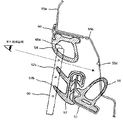
【解決手段】 車体のドア開口部の車外側端部にはモール(10)が装着され、ドアガラス(2)は、インナサッシ(1)の車外側にて、当該インナサッシ(1)に沿って昇降する。この構成において、ドア閉時にインナサッシ(1)とドア開口部との間をシールするメインシール(8)と、インナサッシ(1)とドアガラス(2)との間をシールするガラスシール(3)と、モール(10)に取り付けられ、ドア閉時かつドアガラス(2)閉時に、モール(10)とドアガラス(2)の上端部との間をシールする見切りシール(7)とを有する。ここで見切りシール(7)は、ドア閉時にインナサッシ(1)と接触して、モール(10)とインナサッシ(1)との間をもシールする。
【選択図】 図3PROBLEM TO BE SOLVED: To provide a highly reliable flash surface door by realizing a door seal structure for improving water tightness and air tightness of an inner sash door.
SOLUTION: A molding (10) is mounted on an outer end portion of a vehicle body door opening, and a door glass (2) is moved up and down along the inner sash (1) on the outer side of the inner sash (1). To do. In this configuration, a main seal (8) that seals between the inner sash (1) and the door opening when the door is closed, and a glass seal (3) that seals between the inner sash (1) and the door glass (2). And a parting seal (7) which is attached to the molding (10) and seals between the molding (10) and the upper end of the door glass (2) when the door is closed and the door glass (2) is closed. Here, the parting seal (7) contacts the inner sash (1) when the door is closed, and also seals between the molding (10) and the inner sash (1).
[Selection] Figure 3
Description
本発明は、自動車のドアシール構造に関する。 The present invention relates to an automobile door seal structure.
従来より、外観デザインと風騒音低減などの観点から、車体のフラッシュサーフェイス化の要求がある。また、今後のデザイントレンドとして、ドアガラスの周囲、特にドアガラスの上端縁に沿って金属製モールを設けることが注目されつつある。このようなフラッシュサーフェイス化および金属製モールの採用の観点からすると、通常のサッシドアは不利である。なぜなら、サッシドアでは、金属製モールを車体側に設けた場合には、金属製モールとドアガラスとの間にサッシ上端部が介在してしまいそもそもデザインが成立しないし、かといって、金属製モールをサッシの上端部に設けるようにしたのでは、フロントドアとリアドアとの間で金属製モールの切れ目を作らざるをえず、デザイン上好ましくないからである。 Conventionally, there has been a demand for a flash surface of a vehicle body from the viewpoint of appearance design and wind noise reduction. Further, as a future design trend, it has been noticed that a metal molding is provided around the door glass, particularly along the upper edge of the door glass. From the viewpoint of such flash surface formation and adoption of a metal molding, a normal sash door is disadvantageous. Because, in the case of a sash door, when a metal molding is provided on the vehicle body side, the upper end of the sash is interposed between the metal molding and the door glass, so the design is not established in the first place. Is provided at the upper end of the sash, it is unavoidable to make a metal molding cut between the front door and the rear door.
フラッシュサーフェイス化の要求に応え、なおかつ、上記した金属製モールとの相性が良いドア構造としては、サッシを設けないサッシレスドア、あるいはサッシをドアガラスの車内側に設けたインナサッシドアが考えられる。しかし、サッシレスドアは、シール性およびガラス保持性の弱さ等があり、一般にも幅広く用いられるには至っていない。これに対し、もう一方のインナサッシドアは、サッシレスドアと比べるとガラス保持性を高めることが可能である点で有利である。 As a door structure that meets the demand for a flash surface and has good compatibility with the metal molding described above, a sashless door without a sash or an inner sash door with a sash provided inside the door glass can be considered. However, sashless doors have poor sealing performance and glass retention, and have not been widely used in general. On the other hand, the other inner sash door is advantageous in that the glass retainability can be improved as compared with the sashless door.
従来のインナサッシドアのシール構造は例えば、実公平7−42827号公報(特許文献1)に開示されている。同文献に開示されているシール構造は図5に示すようなものである。 A conventional inner sash door seal structure is disclosed in, for example, Japanese Utility Model Publication No. 7-42827 (Patent Document 1). The seal structure disclosed in this document is as shown in FIG.
図5において、51がサッシ(インナサッシ)、60がサッシ51の車外側にて、そのサッシ51に沿って上下するガラスである。ボディパネルのドア用段部側壁55bにはリテーナ50が配され、ここに見切りシール54が取り付けられている。また、サッシ51には、メインシール56およびグラスラン57が取り付けられている。ドア閉時、メインシール56はボディパネルのドア用段部底壁55cと接触する。一方のグラスラン57は斜上向シール部57a、57bを有し、これら斜上向シール部57a、57bがガラス60に接触している。さらに、ドア閉かつガラス60の閉時には、ガラス60の上端部60aが見切りシール54に接触する。すなわち、ガラス60は、見切りシール54とグラスラン57とによってシールされる構成である。
In FIG. 5, 51 is a sash (inner sash), and 60 is a glass that moves up and down along the
しかしながら、従来のインナサッシドアのシール構造では、依然としてそのシール性能が弱く、水密性、気密性に問題があった。 However, the conventional inner sash door seal structure still has a poor sealing performance and has problems of water tightness and air tightness.
そこで、本発明は、インナサッシドアの水密性、気密性を向上させるドアシール構造を実現し、もって信頼性の高いフラッシュサーフェイスドアを提供することを目的とする。 Accordingly, an object of the present invention is to provide a door surface structure that improves the watertightness and airtightness of the inner sash door, and to provide a highly reliable flash surface door.
本発明の一側面は、車体のドア開口部の車外側端部に装着されるモールと、ドアの窓枠であるインナサッシと、前記インナサッシの車外側にて当該インナサッシに沿って昇降するドアガラスとを備える自動車のドアシール構造に係り、ドア閉時に前記インナサッシと前記ドア開口部との間をシールするメインシールと、前記インナサッシと前記ドアガラスとの間をシールするガラスシールと、前記モールに取り付けられ、ドア閉時かつ前記ドアガラス閉時に、前記モールと前記ドアガラスの上端部との間をシールする見切りシールとを有し、前記見切りシールは、ドア閉時に前記インナサッシと接触して、前記モールと前記インナサッシとの間もシールすることを特徴とする。 One aspect of the present invention is a molding that is mounted on the vehicle outer end of the door opening of the vehicle body, an inner sash that is a window frame of the door, and a door glass that moves up and down along the inner sash on the vehicle outer side of the inner sash. A main seal that seals between the inner sash and the door opening when the door is closed, a glass seal that seals between the inner sash and the door glass, and is attached to the molding. A parting seal that seals between the molding and an upper end portion of the door glass when the door is closed and the door glass is closed, and the parting seal contacts the inner sash when the door is closed, And the inner sash are also sealed.
この構成によれば、見切りシールは、ドアガラスの上端部のみならず、インナサッシとも接触して二重にシールでき水密性および気密性が向上させることができる。これにより信頼性の高いフラッシュサーフェイスドアを提供することが可能になる。 According to this configuration, the parting seal can be sealed in contact with not only the upper end portion of the door glass but also the inner sash, so that watertightness and airtightness can be improved. This makes it possible to provide a highly reliable flash surface door.
本発明の好適な実施形態によれば、前記モールは、前記ドア開口部の前記車外側端部から前記ドアガラスの昇降軌跡に沿って延出する下垂部を有し、前記ドアガラスの上端部が当該ドアガラス閉時にガラス吸出し方向に抗して該下垂部に支持されることが好ましい。 According to a preferred embodiment of the present invention, the molding has a hanging part that extends from the vehicle outer end of the door opening along the up-and-down trajectory of the door glass, and the upper end of the door glass. Is preferably supported by the hanging portion against the glass suction direction when the door glass is closed.
この構成によれば、前記下垂部をドアガラスの上端縁に沿う装飾部材として機能させつつ、その下垂部を利用してガラス吸出しを防止することができる。 According to this configuration, it is possible to prevent the glass from being sucked out using the hanging portion while the hanging portion functions as a decorative member along the upper edge of the door glass.
本発明の好適な実施形態によれば、前記見切りシールは、前記下垂部の車内側にて収容され、車外からの車両側面視で、前記下垂部によって大部分が隠蔽されることが好ましい。 According to a preferred embodiment of the present invention, it is preferable that the parting seal is accommodated inside the hanging part and is largely concealed by the hanging part in a side view of the vehicle from the outside of the vehicle.
この構成によれば、前記下垂部によって車外から見切りシールが見えないようにすることができる。この場合、シール性能を向上させるために見切りシールを大きくしても、前記下垂部によってその見切りシールを隠すことが可能である。これにより、外観の意匠性を向上させることができる。また、見切りシールは前記下垂部によって支持できるので、シール倒れのおそれもない。 According to this configuration, it is possible to prevent the parting seal from being seen from outside the vehicle by the hanging portion. In this case, even if the parting seal is enlarged to improve the sealing performance, the parting seal can be hidden by the hanging part. Thereby, the designability of an external appearance can be improved. Further, since the parting seal can be supported by the hanging part, there is no risk of the seal falling down.
また、本発明の好適な実施形態によれば、前記下垂部の車内側に、前記見切りシールを収容するための凹部を設けることが好ましい。 Moreover, according to a preferred embodiment of the present invention, it is preferable that a recess for accommodating the parting seal is provided on the vehicle interior side of the hanging part.
この構成によれば、より大型の見切りシールを採用することができ、これによりシール性能を更に高めることができる。 According to this configuration, it is possible to employ a larger parting seal, thereby further enhancing the sealing performance.
ところで、図5に示したような従来のシール構造の場合には、ガラス60を下げたときに、同図の車外側側面視としての目線で示されるように、サッシ51と見切りシール54との間からボディパネル(ドア用段部底壁55c)が露見してしまい、見映えのよいものではなかった。
By the way, in the case of the conventional seal structure as shown in FIG. 5, when the
この点、本発明の好適な実施形態によれば、ドア閉時において、前記下垂部の下端縁と前記インナサッシの上端縁とが略同一高さに位置するように設定される。このため、ドアガラスを少し下げたときにも前記ドア開口部は車外に露見することはなく、このときの見映えを向上させることができる。 In this regard, according to a preferred embodiment of the present invention, when the door is closed, the lower end edge of the hanging part and the upper end edge of the inner sash are set to be substantially at the same height. For this reason, even when the door glass is slightly lowered, the door opening is not exposed outside the vehicle, and the appearance at this time can be improved.
さらに、本発明の好適な実施形態によれば、前記インナサッシは閉断面形状を有し、前記メインシールは、前記ドア開口部の車室内側に形成されたフランジ部に装着されることが好ましい。 Furthermore, according to a preferred embodiment of the present invention, it is preferable that the inner sash has a closed cross-sectional shape, and the main seal is attached to a flange portion formed on the vehicle interior side of the door opening.
この構成によれば、インナサッシを閉断面として高剛性にできる一方、メインシールをこのインナサッシに取り付けにくくなるところ、メインシールは車体側に形成されたフランジ部に装着するようにしたので、メインシールの取り付け容易性を確保できる。また、メインシールはドア側に付いているよりも車体側に付いている方が見映えもよい。 According to this configuration, the inner sash can be made highly rigid with a closed cross section, while the main seal is difficult to attach to the inner sash, but the main seal is attached to the flange formed on the vehicle body side. Easy installation is ensured. Also, the main seal looks better on the vehicle body side than on the door side.
本発明によれば、インナサッシドアの水密性、気密性を向上させるドアシール構造が実現され、もって信頼性の高いフラッシュサーフェイスドアを提供することができる。 ADVANTAGE OF THE INVENTION According to this invention, the door seal structure which improves the watertightness of an inner sash door and an airtightness is implement | achieved, Therefore A flash surface door with high reliability can be provided.
以下、図面を参照して本発明の好適な実施形態について詳細に説明する。なお、本発明は以下の実施形態に限定されるものではなく、本発明の実施に有利な具体例を示すにすぎない。また、以下の実施形態の中で説明されている特徴の組み合わせの全てが本発明の課題解決手段として必須のものとは限らない。 DESCRIPTION OF EMBODIMENTS Hereinafter, preferred embodiments of the present invention will be described in detail with reference to the drawings. In addition, this invention is not limited to the following embodiment, It shows only the specific example advantageous for implementation of this invention. Further, not all combinations of features described in the following embodiments are essential as the problem solving means of the present invention.
図1は、本発明のドアシール構造を採用した自動車の側面外観を示す図である。この自動車には、フロントピラー〜ルーフサイドレール〜リアピラーに亘り、フロントドアおよびリアドアそれぞれのドアガラス2,2の上端縁に沿って、外装部材であるモール10が装着されている。このようなモール10は例えばステンレススチールで構成され、近年のデザイントレンドとして注目されているものである。ここで、このようなモールを車体側に装着する態様とドア側に装着する態様が考えられるが、ドア側に装着した場合にはモールはフロントドアとリアドアとの間で途切れざるをえず、外観デザインの観点からは好ましくない。そこで本実施形態では、フロントドアおよびリアドアにはいわゆるインナサッシドアを採用する。それとともに、モール10にはフロントドア、リアドアごとに分かれた別個のものを使用するのではなく、同図上部に別に描いたように、一体的に構成されたものを使用して、これを車体のドア開口部の車外側端部に装着する。これにより特徴的な外装デザインが実現される。
FIG. 1 is a view showing a side appearance of an automobile employing the door seal structure of the present invention. The automobile is provided with a
以下、図1に示した本実施形態に係る自動車のドアシール構造を図2〜図4を参照して詳細に説明する。図2および図3は図1のA−A断面図で、それぞれドア開時、ドア閉時を示している。これらの図は本実施形態におけるドアシール構造の一例を端的に示しており、とりわけ図5の従来構造と図2,3の本実施形態に係る構造とを照らし合わせつつ、以下の説明を読めば本発明の特徴および利点が容易に理解されよう。なお、これら図2および図3は図1のA−A断面であるから、そこに示されるドアシール構造はフロントドアにおけるものであるが、リアドアにも同様のドアシール構造を適用できることはいうまでもない。したがって以下では、代表的に図1のA−A断面に係るフロントドアのドアシール構造について説明することとし、リアドアのそれについては説明を省略する。 Hereinafter, the door seal structure of the automobile according to the present embodiment shown in FIG. 1 will be described in detail with reference to FIGS. 2 and 3 are cross-sectional views taken along the line A-A in FIG. 1, and show the door opening time and the door closing time, respectively. These drawings briefly show an example of the door seal structure in the present embodiment. In particular, the book structure will be described if the following explanation is read while comparing the conventional structure in FIG. 5 with the structure according to the present embodiment in FIGS. The features and advantages of the invention will be readily appreciated. 2 and 3 are cross-sectional views taken along the line AA of FIG. 1, the door seal structure shown therein is for the front door, but it goes without saying that the same door seal structure can be applied to the rear door. . Therefore, hereinafter, the door seal structure of the front door according to the AA cross section of FIG. 1 will be described as a representative, and the description of the rear door will be omitted.
図2および図3において、図面左側が車外側、右側が車内側であり、X−X線はドア開閉方向を示している。また、図3におけるY−Y線はドアガラスの吸出し方向を示すものとする。さて、図2および図3において、1がドアの窓枠であるインナサッシ、2がインナサッシ1の車外側にてこのインナサッシ1に沿って昇降するドアガラスである。本実施形態におけるインナサッシ1は図示の如く閉断面形状を有しており、これによって十分な剛性を確保している。また、このインナサッシ1の車外側にはリテーナが形成され、ここにガラスシール3が装着されている。ドアガラス2の閉時には、このガラスシール3によってインナサッシ1とドアガラス2との間がシールされることになる。
2 and 3, the left side of the drawing is the vehicle outer side, the right side is the vehicle inner side, and the XX line indicates the door opening / closing direction. Moreover, the YY line in FIG. 3 shall show the suction direction of a door glass. 2 and 3,
車体のドア開口部の上端縁部をなすルーフサイドレールは、その車外側を構成するとともにドアとの係合面を形成するルーフサイドレールアウタ5a〜5dと、その車内側を構成するルーフサイドレールインナ11とで構成されている。ここでルーフサイドレールアウタ5dとルーフサイドレールアウタ11との重なり部分は下方に延出され、フランジ12が形成されている。そしてここに、中空ゴム製のメインシール8が嵌着される。このメインシール8によって、ドア閉時にインナサッシ1とドア開口部との間がシールされる。
The roof side rail that forms the upper edge of the door opening of the vehicle body includes the roof
もっとも、ドア閉時にインナサッシ1とドア開口部との間をシールできるかぎり、このメインシール8をインナサッシ1側に装着する構成としてもよい。ただし本実施形態では、上記のようにインナサッシ1を閉断面形状としたため、インナサッシ1にメインシール8を装着するためにはそのためのリテーナを更に形成する必要があり、インナサッシ1自体の形状をさらに複雑なものにせざるをえない。そうするよりもむしろ、上記の如くルーフサイドレールアウタ5dとルーフサイドレールアウタ11との重なり部分でフランジ12を形成し、ここにメインシール8を取り付ける方が構造的に簡単で済み、メインシール8の取り付け容易性を確保することができる。また、メインシール8はドア側に付いているよりも車体側に付いている方が見映えも良いであろう。
However, as long as the space between the
続いて、本実施形態におけるモール10について詳しく説明する。モール10は、ルーフサイドレールアウタの車外側表面5aの下端部(すなわち、ドア開口部の車外側端部)において、その表面がルーフサイドレールアウタの車外側表面5aと略同一面となるように装着される。例えば、図2および図3に示すように、モール10の上部は裏側(車内側)に折り返されて、その上部において更に、モール10の表面とは垂直に車内側に延出するフランジ10aが形成されている。そしてモール10は、このフランジ10aがルーフサイドレールアウタの車外側底面5bと例えば接着されることで、ルーフサイドレールに取り付けられる。また、このモール10の下部も裏側(車内側)に折り返されてこのモール10の上部の、フランジ10aと対向する位置にリテーナ10bが形成される。ここに、中空ゴム製の見切りシール7が装着される。この見切りシール7によって、ドア閉時かつドアガラス2の閉時に、モール10とドアガラス2の上端部との間がシールされる(図3を参照)。
Next, the
モール10には、フランジ10aおよびリテーナ10bがその上部位置の裏側に形成される結果、ルーフサイドレールアウタの車外側表面5aの下端部(すなわち、ドア開口部の車外側端部)からドアガラス2の昇降軌跡に沿って延出する下垂部10cが形成される。そして、図3に示すようなドア閉時かつドアガラス2閉時においては、ドアガラス2の上端部はY−Y線で示されたガラス吸出し方向に抗して下垂部10cに支持される。したがって、下垂部10cの表面は基本的に装飾部材として機能する一方、この下垂部10cを利用して、ガラス吸出しを防止することができる。
As a result of the
この場合、見切りシール7はこの下垂部10cの車内側にて収容される構成となる。この構成によれば、車外からの車両側面視で見切りシール7の大部分を下垂部10cによって隠蔽することができる。これにより、外観の意匠性を向上させることができる。さらにこの構成によると、モール10は、この下垂部10cの存在によって、見切りシール7の車外方向への変形を規制するホルダとしても機能することとなる。これにより見切りシール7のシール倒れのおそれもなくなる。
In this case, the parting seal 7 is configured to be accommodated inside the hanging
また本実施形態では、ルールサイドレールアウタの車外側底部5bと車内側底部5dとの段差を設けることにより、その車外側底部5bと、その車外側底部5b−車内側底部5d間をつなぐ側面5cと、モール10の下垂部10cとで構成される凹部6を設けた。つまり、見切りシール7はこの凹部6内に収容されるかたちになる。こうすることで、シール性能を向上させるために見切りシール7を大きくしても、下垂部10cによってその見切りシール7を隠すことが可能である。これにより、モール10による美観を損なうことなく容易に見切りシール7のシール性能を高めることができる。
In this embodiment, by providing a step between the vehicle
図4は、図1のB−B線に沿う断面を示す斜視図である。図4では、図面上側が車外側、図面下側が車内側を示している。同図において、図面左上の参照番号2はフロントドアのドアガラス、図面右下の参照番号2はリアドアのドアガラスである。そして、図面中央部にセンタピラー周りの断面が示されている。フロントドア2とリアドア2の間に位置するセンタピラーはセンタピラーアウタ22、センタピラーインナ23、およびセンタピラートリム24で構成され、図示の如く閉断面が形成されている。センタピラーアウタ22とセンタピラーインナ23との重なり部分はそれぞれ車体前方および後方にフランジとして延出され、そこに中空ゴム製のセンタピラー部メインシール28が装着されている。なお、図示は省略するが、このセンタピラーの上端は上述のルーフサイドレールアウタ5dと接続される。
4 is a perspective view showing a cross section taken along line BB in FIG. In FIG. 4, the upper side of the drawing shows the vehicle outer side, and the lower side of the drawing shows the vehicle inner side. In the figure,
参照番号21はドアに設けられる窓枠としてのセンタピラー部インナサッシで、ガラス2を摺動可能に保持している。また、このセンタピラー部インナサッシ21の車内側にはリテーナが形成され、ここに中空ゴム製のセンタピラー部見切りシール27が装着されている。したがってこの例の場合、ドア閉時にはセンタピラー部インナサッシ21とセンタピラーアウタ22との間は、センタピラー部メインシール28とセンタピラー部見切りシール27の2つによってシールされることになる。
また、図4の右下部にはドア上端部におけるドアシール構造が示されており、これは図3に示された断面の斜視図に相当する(ただし、リアドア側)。なお、参照番号13はルールサイドレール部の内装部材としてのルールトリムである。
4 shows a door seal structure at the upper end portion of the door, which corresponds to the perspective view of the cross section shown in FIG. 3 (however, on the rear door side).
以上説明した図4により、本実施形態のインナサッシ構造における、センタピラー部でのガラス2の摺動保持構造がいっそう明確に理解されよう。また、このようなインナサッシ構造によって、モール10をセンタピラーによって途切れさせる必要はなく、一体的に構成されたもの(図1を参照)を使用できるようになっている点も重要である。
With reference to FIG. 4 described above, the sliding holding structure of the
本実施形態におけるドアシール構造は概ね上記のとおりである。ドア閉時には、メインシール8はインナサッシ1と接触して、インナサッシ1とドア開口部との間がシールされる。これは先述したとおりであるが、本実施形態ではこれに加えて、図3に示すように見切りシール7もがインナサッシ1と接触して、モール10とインナサッシ1との間が同時にシールされる。これが本実施形態の構成で最も重要なポイントである。要するに、ドア閉時において、見切りシール7はドアガラス2の閉時にドアガラス2の上端部と接触するだけではなく、更にインナサッシ1とも接触して二重のシールを行う。図5に示した従来構造では、ドア閉かつガラス60の閉時においても、見切りシール54とインナサッシ51との間に空隙が存在しており、水密性、気密性に弱さがあることは否めない。しかも、ガラス60を少し下げただけで雨滴や空気がその空隙に入り込むことになる。これに対し、図3に示したような本実施形態の構成では従来のような空隙は存在せず、水密性、気密性が増すことは容易に理解されよう。また、ドアガラス2を少し下げたところで雨滴や空気がインナサッシ1よりも車内側に入り込む余地はない。よって、本実施形態のドアシール構造により、信頼性の高いフラッシュサーフェイスドアを提供することができる。
The door seal structure in the present embodiment is generally as described above. When the door is closed, the main seal 8 comes into contact with the
また、この構成においては、モール10の下垂部10cの下端縁とインナサッシ1の上端縁とは、略同一高さに位置していることが望ましい。このような位置関係であれば、図2および図3の車外側側面視としての目線で示されるように、ドアガラス2を少し下げたときでも車体側のドア開口部が車外に露見することはなく、このときの見映えを向上させることができるからである。
Further, in this configuration, it is desirable that the lower end edge of the hanging
1 インナサッシ
2 ドアガラス
3 ガラスシール
5a ルーフサイドレールアウタの車外側表面部
5b ルーフサイドレールアウタの車外側底部
5c ルーフサイドレールアウタの中間側面部
5d ルーフサイドレールアウタの車内側底部
6 凹部
7 見切りシール
8 メインシール
10 モール
10a モールのフランジ部
10b モールのリテーナ部
10c モールの下垂部
11 ルーフサイドレールインナ
12 ルーフサイドレールのフランジ部
DESCRIPTION OF
Claims (6)
ドアの窓枠であるインナサッシと、
前記インナサッシの車外側にて当該インナサッシに沿って昇降するドアガラスと、
を備える自動車のドアシール構造であって、
ドア閉時に前記インナサッシと前記ドア開口部との間をシールするメインシールと、
前記インナサッシと前記ドアガラスとの間をシールするガラスシールと、
前記モールに取り付けられ、ドア閉時かつ前記ドアガラス閉時に、前記モールと前記ドアガラスの上端部との間をシールする見切りシールと、を有し、
前記見切りシールは、ドア閉時に前記インナサッシと接触して、前記モールと前記インナサッシとの間もシールすることを特徴とするドアシール構造。 A mall mounted on the vehicle outer end of the door opening of the vehicle body;
With the inner sash that is the window frame of the door,
A door glass that moves up and down along the inner sash on the outer side of the inner sash;
A door seal structure of an automobile comprising:
A main seal that seals between the inner sash and the door opening when the door is closed;
A glass seal that seals between the inner sash and the door glass;
A parting seal that is attached to the molding and seals between the molding and the upper end of the door glass when the door is closed and the door glass is closed;
The parting seal is in contact with the inner sash when the door is closed, and seals between the molding and the inner sash.
前記メインシールは、前記ドア開口部の車室内側に形成されたフランジ部に装着される
ことを特徴とする請求項5に記載のドアシール構造。 The inner sash has a closed cross-sectional shape;
The door seal structure according to claim 5, wherein the main seal is attached to a flange portion formed on the vehicle interior side of the door opening.
Priority Applications (1)
| Application Number | Priority Date | Filing Date | Title |
|---|---|---|---|
| JP2005128476A JP2006306168A (en) | 2005-04-26 | 2005-04-26 | Automotive door seal structure |
Applications Claiming Priority (1)
| Application Number | Priority Date | Filing Date | Title |
|---|---|---|---|
| JP2005128476A JP2006306168A (en) | 2005-04-26 | 2005-04-26 | Automotive door seal structure |
Publications (1)
| Publication Number | Publication Date |
|---|---|
| JP2006306168A true JP2006306168A (en) | 2006-11-09 |
Family
ID=37473559
Family Applications (1)
| Application Number | Title | Priority Date | Filing Date |
|---|---|---|---|
| JP2005128476A Abandoned JP2006306168A (en) | 2005-04-26 | 2005-04-26 | Automotive door seal structure |
Country Status (1)
| Country | Link |
|---|---|
| JP (1) | JP2006306168A (en) |
Cited By (4)
| Publication number | Priority date | Publication date | Assignee | Title |
|---|---|---|---|---|
| JP2010526720A (en) * | 2007-05-15 | 2010-08-05 | ルノー・エス・アー・エス | Automotive window frame mounting parts |
| JP2020032821A (en) * | 2018-08-28 | 2020-03-05 | 本田技研工業株式会社 | Arrangement structure of vehicle imaging unit |
| CN113815391A (en) * | 2021-10-11 | 2021-12-21 | 上海荣南科技股份有限公司 | A window frame concealed door structure with a low top configuration |
| CN114228452A (en) * | 2021-10-11 | 2022-03-25 | 上海荣南科技股份有限公司 | Window frame hidden vehicle door structure with high-configuration top |
Citations (6)
| Publication number | Priority date | Publication date | Assignee | Title |
|---|---|---|---|---|
| JPS58132720U (en) * | 1982-03-03 | 1983-09-07 | トヨタ自動車株式会社 | car door window structure |
| JPS62121145U (en) * | 1986-01-25 | 1987-07-31 | ||
| JPS6313353U (en) * | 1986-07-11 | 1988-01-28 | ||
| JPS6377868U (en) * | 1986-11-10 | 1988-05-23 | ||
| JPH0159724U (en) * | 1987-10-12 | 1989-04-14 | ||
| JPH01233116A (en) * | 1988-03-15 | 1989-09-18 | Mazda Motor Corp | Door structure of vehicle |
-
2005
- 2005-04-26 JP JP2005128476A patent/JP2006306168A/en not_active Abandoned
Patent Citations (6)
| Publication number | Priority date | Publication date | Assignee | Title |
|---|---|---|---|---|
| JPS58132720U (en) * | 1982-03-03 | 1983-09-07 | トヨタ自動車株式会社 | car door window structure |
| JPS62121145U (en) * | 1986-01-25 | 1987-07-31 | ||
| JPS6313353U (en) * | 1986-07-11 | 1988-01-28 | ||
| JPS6377868U (en) * | 1986-11-10 | 1988-05-23 | ||
| JPH0159724U (en) * | 1987-10-12 | 1989-04-14 | ||
| JPH01233116A (en) * | 1988-03-15 | 1989-09-18 | Mazda Motor Corp | Door structure of vehicle |
Cited By (4)
| Publication number | Priority date | Publication date | Assignee | Title |
|---|---|---|---|---|
| JP2010526720A (en) * | 2007-05-15 | 2010-08-05 | ルノー・エス・アー・エス | Automotive window frame mounting parts |
| JP2020032821A (en) * | 2018-08-28 | 2020-03-05 | 本田技研工業株式会社 | Arrangement structure of vehicle imaging unit |
| CN113815391A (en) * | 2021-10-11 | 2021-12-21 | 上海荣南科技股份有限公司 | A window frame concealed door structure with a low top configuration |
| CN114228452A (en) * | 2021-10-11 | 2022-03-25 | 上海荣南科技股份有限公司 | Window frame hidden vehicle door structure with high-configuration top |
Similar Documents
| Publication | Publication Date | Title |
|---|---|---|
| JP4729087B2 (en) | Vehicle door structure | |
| EP2711220B1 (en) | Assembly structure of wheather strip | |
| US20050229496A1 (en) | Door sash structure | |
| CN101795898B (en) | Installation structure of frame decoration | |
| JP2018177045A (en) | Automotive door seal structure | |
| US20170355253A1 (en) | Sealing structure for automobile | |
| JP2009078665A (en) | Door weather strip | |
| JP4364707B2 (en) | Door glass seal structure | |
| JP2014193632A (en) | Door glass seal structure for vehicle | |
| JP4402550B2 (en) | Weather strip for rear door with parting seal | |
| JP2009262617A (en) | Door structure of vehicle | |
| JP4520805B2 (en) | Door weather strip and door seal structure | |
| JP2009078683A (en) | Door glass run structure | |
| JP5651720B2 (en) | Vehicle door with mirror | |
| JP2010215049A (en) | Door weatherstrip | |
| JP2010023650A (en) | Vehicular door structure | |
| JP2003136961A (en) | Door glass run mounting structure | |
| JP2007223467A (en) | Back door seal structure | |
| JPS6012736Y2 (en) | Automotive side door corner bracket mounting structure | |
| JP2541836Y2 (en) | Grass-run structure of the lifting window | |
| JP5162769B2 (en) | Mounting structure for automotive weather strip | |
| JPS5989221A (en) | Car door structure | |
| JPH1159179A (en) | Car door seal structure | |
| JPH09301092A (en) | Roof weather strip | |
| JP2007216893A (en) | Back door seal structure |
Legal Events
| Date | Code | Title | Description |
|---|---|---|---|
| A621 | Written request for application examination |
Free format text: JAPANESE INTERMEDIATE CODE: A621 Effective date: 20080206 |
|
| A977 | Report on retrieval |
Free format text: JAPANESE INTERMEDIATE CODE: A971007 Effective date: 20100624 |
|
| A131 | Notification of reasons for refusal |
Free format text: JAPANESE INTERMEDIATE CODE: A131 Effective date: 20100705 |
|
| A762 | Written abandonment of application |
Free format text: JAPANESE INTERMEDIATE CODE: A762 Effective date: 20100929 |