JP2006292041A - Shock absorber - Google Patents
Shock absorber Download PDFInfo
- Publication number
- JP2006292041A JP2006292041A JP2005112185A JP2005112185A JP2006292041A JP 2006292041 A JP2006292041 A JP 2006292041A JP 2005112185 A JP2005112185 A JP 2005112185A JP 2005112185 A JP2005112185 A JP 2005112185A JP 2006292041 A JP2006292041 A JP 2006292041A
- Authority
- JP
- Japan
- Prior art keywords
- piston
- chambers
- cylinder
- shock absorber
- chamber
- Prior art date
- Legal status (The legal status is an assumption and is not a legal conclusion. Google has not performed a legal analysis and makes no representation as to the accuracy of the status listed.)
- Pending
Links
Images


Abstract
Description
本発明は、自動車などの車両の懸架装置に用いられる減衰力可変のショックアブソーバに関する。 The present invention relates to a shock absorber with variable damping force used for a suspension device of a vehicle such as an automobile.
従来、減衰力が可変のショックアブソーバとしては、例えば特許文献1に記載のショックアブソーバがある。
このショックアブソーバでは、ピストンによってシリンダ内が上部室と下部室との2室に画成されると共に、上記2室を連通すると共に減衰力発生機構を有する主油液通路と、2室を連通するバイパス通路と、該バイパス通路の開口面積を調整するスプール弁と、該スプール弁のスプールを駆動するアクチュエータとを備えている。さらに、上記スプール弁の弁ハウジング内の上記スプールの両端側に、上記スプールが開口面積を開く方向に摺動したときに拡張される一端側の室、及び圧縮される他端側の室を形成すると共に、該他端側の室に上記油液よりも体積弾性係数が小さな物質を設け、且つ、上記スプールの一端側の室と上記シリンダ内の下部室とを連通路で連通すると共に、上記スプールの他端側の室と上記シリンダ内の下部室をオリフィス通路で連通させている。
Conventionally, as a shock absorber with variable damping force, for example, there is a shock absorber described in
In this shock absorber, the interior of the cylinder is defined by the piston into two chambers, an upper chamber and a lower chamber, and the two chambers communicate with each other and communicate with the main fluid passage having the damping force generation mechanism. A bypass passage, a spool valve that adjusts the opening area of the bypass passage, and an actuator that drives the spool of the spool valve are provided. Furthermore, a chamber on one end side that is expanded when the spool slides in a direction to open an opening area and a chamber on the other end side to be compressed are formed on both end sides of the spool in the valve housing of the spool valve. In addition, a material having a smaller volume modulus of elasticity than the oil liquid is provided in the chamber on the other end side, and the chamber on one end side of the spool and the lower chamber in the cylinder are communicated with each other through a communication path. A chamber on the other end side of the spool is communicated with a lower chamber in the cylinder through an orifice passage.
このショックアブソーバによれば、下部室が加圧されると、その圧力によって、油液が下部室から連通路及びオリフィス通路を介してスプールの両端側の室内に流入する。このとき、ピストンロッドの作動速度が大きいほど、スプールの一端側の室の圧力が相対的に低くなることでスプールがバイパス通路を開く方向に移動して減衰力の上昇を抑える。
上記構成のショックアブソーバでは、減衰力抑制のためにバイパス通路の流路面積を大きく取ろうとすると、減衰力の抑制に伴う下部室の圧力の抜けが大きくなることで、スプールがバイパス通路を閉じる方向に移動してバイパス通路を閉じてしまうおそれがあるという課題がある。
本発明は、上記のような点に着目してなされたもので、より適正に減衰力の自動的な可変調整が可能なショックアブソーバを提供することを課題としている。
In the shock absorber having the above-described configuration, when the flow passage area of the bypass passage is increased in order to suppress the damping force, the pressure in the lower chamber is increased due to the suppression of the damping force, so that the spool closes the bypass passage. There exists a subject that there exists a possibility of moving to and closing a bypass channel.
The present invention has been made paying attention to the above points, and it is an object of the present invention to provide a shock absorber capable of appropriately and automatically adjusting the damping force more appropriately.
上記課題を解決するために、本発明は、シリンダと、そのシリンダ内を2室に画成するピストンと、ピストンに連結してシリンダの外まで延びるピストンロッドとを備えたショックアブソーバにおいて、上記ピストンで画成される2室を連通する連通路と、上記2つの室のうちの一方の室に配置されて上記ピストンに連動して進退する区画部材と、を備え、その区画部材の進退速度に応じて上記連通路の開口面積が調整されることを特徴とするものである。 In order to solve the above problems, the present invention provides a shock absorber comprising a cylinder, a piston that defines the inside of the cylinder in two chambers, and a piston rod that is connected to the piston and extends to the outside of the cylinder. And a partition member that is disposed in one of the two chambers and that moves forward and backward in conjunction with the piston, and is adapted to the advance and retreat speed of the partition member. Accordingly, the opening area of the communication path is adjusted.
本発明によれば、より適正に減衰力の自動的な可変調整が可能なショックアブソーバを提供できる。 According to the present invention, it is possible to provide a shock absorber capable of appropriately and automatically adjusting the damping force.
次に、本発明の第1実施形態について図面を参照しつつ説明する。
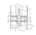
まず、構成について説明すると、図1及び図2に示すように、シリンダ1内がピストン2によって上部室URと下部室LRとの2室に画成され、該ピストン2に連結したピストンロッド3が上方に延びている。そのピストンロッド3の上端部が不図示の車体フレームに連結している。
Next, a first embodiment of the present invention will be described with reference to the drawings.
First, the configuration will be described. As shown in FIGS. 1 and 2, the inside of the
上記ピストン2には、伸び側及び縮み側用の第1連通路4がそれぞれ設けられ、該第1連通路4によって上部室URと下部室LRとを連通している。各第1連通路4の上部室UR側開口部若しくは下部室LR側開口部にはそれぞれリリーフ弁5が設けられ、各リリーフ弁5は、上下の室の圧力差によって上記第1連通路4の開度が調整され、圧力差が大きいほど開度が大きくなる。本実施形態のリリーフ弁5は、ピストン2の表面に対向配置され且つ上記第1連通路4の一方の開口に対向する部分を有した、板状の弾性体から構成され、圧力差に応じて板状の弾性体が撓むことで開度が調整される。
The
また、上記ピストンロッド3の下端部には、下端面から軸方向に延びて上記ピストン2を貫通するスリーブ孔6が開口し、そのスリーブ孔6に下側からスプール7が差し込まれている。そのスプール7の下部は上記スリーブ孔6から下方に突出していて、その端部に対し、区画部材を構成する区画板8が固定されている。上記区画板8は、シリンダ1の内径により若干小径の円板形状をしている。この区画板8によって、下部室LRは軸方向に第1下部室LR1及び第2下部室LR2の2つの室に区画されている。本実施形態では、スプール7の下端部に雄ねじを設け、その雄ねじ部にワッシャ状の区画板8を挿入してナット9を締め付けることで当該区画板8を固定している。
A
また、スプール7の上端部側及び下端部側は、ぞれぞれ小径となっており、スリーブ孔6内に位置する上下の各小径部外周に対して、それぞれ軸方向に付勢するバネ部材10が配置され、該バネ部材10によってスリーブ孔6に対するスプール7の初期位置が位置決めされている。また、符号11は下側のバネ部材10を着座すると共にピストンロッド3下端部に螺合したナットであって、該ナット11によってスリーブ孔6からのスプール7の抜けを防止している。
Further, the upper end side and the lower end side of the
また、上記スプール7には、軸方向に延びる有底孔からなる第2連通路12が開口している。第2連通路12は、上端面から下方に上記区画板8取付け位置上側位置まで軸方向に沿って延びるように形成されている。該第2連通路12の下部は、径方向に延びる下側連通孔13によって下部室LRに連通している。また、上記第2連通路12の上部側にも径方向に延びる上側連通孔14が開口している。
Further, the
また、上記スリーブ孔6が形成されているピストンロッド3には、上記上側連通孔14に対応して、スリーブ孔6と上部室URとを連通する弁ポート15が開口していて、スリーブ孔6に対するスプール7の位置が所定位置に変位したときに上側連通孔14と弁ポート15とが重なることで、第2連通路12を通じて上部室URと下部室LRとが連通するようになっている。
Further, the
次に、上記構成のショックアブソーバの動作や作用効果について説明する。
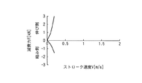
第1連通路4及びリリーフ弁5からなる第1調整弁は、図3に示す基本の減衰特性を有し、さらに、第1調整弁を挟んだ上部室UR及び下部室LRの圧力差が大きくなるとリリーフ弁5が圧力差に応じた分だけ撓んで第1連通路4の開度が大きくなることで、図4に示す減衰力特性が追加される。
Next, the operation and effect of the shock absorber having the above configuration will be described.
The first adjustment valve including the
このように、上記第1調整弁によって、ピストン2を挟んだ上下の室UR、LR(LR1)の圧量差に応じた減衰力特性を備える。
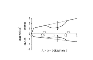
さらに、本実施形態にあっては、スプール7及びスリーブ孔6からなる第2調整弁によって、新たな減衰力特性が追加される。この減衰力調整弁を構成する第2調整弁は、図5に示す比較的小さい減衰力特性を基本として、ストローク速度が中高速域(V1〜V2)では、図6のように弁の開度が大きくなり減衰力の抜けが大きくなる。
Thus, the first adjusting valve has a damping force characteristic corresponding to the pressure difference between the upper and lower chambers UR and LR (LR1) sandwiching the
Furthermore, in this embodiment, a new damping force characteristic is added by the second adjustment valve including the
以上のことから、全体として、図7に示すような減衰力特定となる。すなわち、中高速域(V1〜V2)での減衰力を小さくできるので、たとえば路面の突起乗り越し時の衝撃を緩和できる一方、高速域(V2〜)では、減衰力が高く保たれることで、悪路走破性及び耐久性が確保される。
このとき、上記第2調整弁は、下部室LR内における第1下部室LR1と第2下部室LR2との圧力差によって開度が調整され、該圧力差が所定の範囲(中高速域に対応する圧力差)のときに大きく開くように設定されているため、第1調整弁が開いて上部室URと下部室LR(第1下部室LR1)の圧力差が無くなったり小さくなったりしても、ピストン2が移動している限り上記第1調整弁が開くことで、確実に中高速域の場合には減衰力を小さく設定できる。
From the above, as a whole, the damping force is specified as shown in FIG. That is, since the damping force in the medium and high speed range (V1 to V2) can be reduced, for example, the impact at the time of getting over the bump on the road surface can be reduced, while in the high speed range (V2), the damping force is kept high. Rough road running ability and durability are secured.
At this time, the opening of the second adjustment valve is adjusted by the pressure difference between the first lower chamber LR1 and the second lower chamber LR2 in the lower chamber LR, and the pressure difference is within a predetermined range (corresponding to the middle / high speed range). Therefore, even if the first adjustment valve is opened and the pressure difference between the upper chamber UR and the lower chamber LR (first lower chamber LR1) disappears or decreases, the first adjustment valve opens. As long as the
ここで、上記実施形態の調整弁では、下部室LRにおける区画板8で区画された第1下部室LR1及び第2下部室LR2の圧力差、つまりピストン2のストローク速度(方向も含む)に略比例して区画板8が進退することで、当該第2調整弁の開度が調整されるわけであるが、当該第2調整弁の開度が大きくなるストローク速度の領域は1箇所に限定する必要はなく、減衰力を小さくしたいストローク速度に合わせて2箇所以上で弁が開くように設定しても良い。例えばピストンロッド3に対し軸方向に沿って2箇所以上の位置に弁ポート15を設定したり、軸方向に延びるように弁ポート15の開口形状を設定したりして設定する。
Here, in the regulating valve of the above embodiment, the pressure difference between the first lower chamber LR1 and the second lower chamber LR2 partitioned by the
次に、第2実施形態について図面を参照しつつ説明する。なお、上記第1実施形態と同様な部品等については同一の符号を付して説明する。
本実施形態の基本構成は、上記第1実施形態と同様であるが、図3及び図4に示すように、区画板8及び第2調整弁の機構が異なる。第2実施形態では、上記第2調整弁をロータリ式として、ピストン2のストローク速度に応じて回動変位することで開度を調整するものである。
Next, a second embodiment will be described with reference to the drawings. The same parts as those in the first embodiment will be described with the same reference numerals.
The basic configuration of this embodiment is the same as that of the first embodiment, but the mechanisms of the
本実施形態の調整弁では、ピストンロッド3の下端部に形成したスリーブ孔6に、回動部材であるバルブロッド20が挿入されている。上記バルブロッド20の上端には弾性体21が取り付けられ、該弾性体21によって、無負荷状態におけるバルブロッド20の周方向の初期位置が規制されている。すなわち、バルブロッド20にトルクが入力されると、上記弾性体21に抗してバルブロッド20が当該トルクに応じた量だけ回動変位し、上記トルクが無くなると上記弾性体21によって初期位置に向けて付勢される。上記弾性体21は、ブッシュや捩りバネなどから構成すればよい。
In the regulating valve of the present embodiment, a
上記バルブロッド20内には軸方向に延びる中空部からなる第2連通路12が形成され、その第2連通路12の下部は、下側連通孔13を通じて下部室LRに連通している。また、上記バルブロッド20の上部には径方向に貫通する上側連通孔14が形成されている。また、ピストンロッド3には、上側連通孔14と同じ高さで初期では周方向にずれた位置に弁ポート15か開口していて、上記バルブロッド20が所定量だけ回転変位することで上側連通孔14と弁ポート15とが重なるように設定されている。
A
そして、上記バルブロッド20の下端部に、下部室LRを上下に区画する区画板8が固定されている。
本実施形態の区画板8は、図10(a)(b)に示すように、複数の羽根板8aが周方向に沿って並ぶと共に軸に対して傾斜して配置されることで、羽根車を形成している。そして、区画板8で上下に区画した室LR1,LR2間の圧力差、つまりピストン2のストローク速度に応じた圧によって区画板8が回動変位し、その回動変位によってバルブロッド20も回転変位する。
A
As shown in FIGS. 10 (a) and 10 (b), the
ここで、ピストン2のストローク速度に対するバルブロッド20に入力されるトルクの大きさは、羽根板8aの数、大きさ、形状、傾斜などを調整することで設定できる。
本発明の調整弁では、ピストン2のストローク速度に応じて区画板8の上下に圧力差が発生し、それに伴う流体の移動によって、弾性体21に抗して羽根車からなる区画板8が回動し、弾性体21が発生するばね力と釣り合う回転角度までバルブロッド20が回転変位して当該第2調整弁の開度が調整される。
これによって、第2調整弁は、第1実施形態と同様な減衰力特性を発生して、上記第1実施形態と同様な作用・効果を備える。
Here, the magnitude of the torque input to the
In the regulating valve of the present invention, a pressure difference is generated above and below the
As a result, the second regulating valve generates the same damping force characteristics as in the first embodiment, and has the same functions and effects as those in the first embodiment.
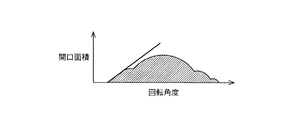
ここで、上記第1及び第2実施形態では、図11に示すように、第2連通路12が大きく開いたとき(V1〜V2)に流量が増大して減衰力の増加を部分的に抑制できるが、上記構造(スプール7若しくはバルブロッド20に第2連通路12を設けた構造)の第2調整弁では、第2連通路12の流路面積を余り大きくできないので、開口面積の変化率と絶対面積には制約がある。また、上記各実施形態において単純に開口を設けると、例えば回転角度と開口面積との関係は、図12に示す関係であるので、図12中で直線で示すように、急激に開口面積が変化して、緩やかな減衰力変化が付けづらい。また、第2調整弁で調整される部分以外は、第1調整弁による減衰力特性に依存してしまう。これに鑑みた実施形態を以下に示す。
ここで、減衰力特性の一つの理想例を図13に示す。以下の実施形態では、この減衰力特性を狙いとする。
Here, in the first and second embodiments, as shown in FIG. 11, when the
Here, one ideal example of the damping force characteristic is shown in FIG. In the following embodiment, this damping force characteristic is aimed.
次に、第3実施形態について図面を参照しつつ説明する。なお、上記各実施形態と同様な部品等については同一の符号を付して説明する。
本実施形態は、上記第2実施形態と同様に区画板8を構成する羽根車によって回転変位する調整弁を備えるが、該第2調整弁が第1調整弁を兼ねる点が異なる。
Next, a third embodiment will be described with reference to the drawings. Components similar to those in each of the above embodiments will be described with the same reference numerals.
The present embodiment includes an adjustment valve that is rotationally displaced by an impeller that constitutes the
まず、本第3実施形態の構成について説明する。
図14に示すように、ピストンロッド3の下端面から軸方向に延びる有底のスリーブ孔6が形成され、該スリーブ孔6にバルブロッド20が挿入されている。ただし、第2実施形態と異なりバルブロッド20内に連通路用の中空部は不要である(別途設けても良い)。そのバルブロッド20は弾性体であるトーションバー21を介してピストンロッド3に連結し、該トーションバー21によって、バルブロッド20は、周方向における初期位置に付勢されている。
First, the configuration of the third embodiment will be described.
As shown in FIG. 14, a bottomed
上記バルブロッド20の下端部には、回転車からなる区画板8が固定され、上記第2実施形態と同様に、該区画板8が回動することで、上記トーションバー21のバネ力に抗して回転変位するようになっている。
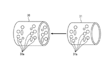
さらに、入れ子状に配置された外筒30及び内筒31を備える。外筒30は、ピストン2よりも小径の円筒からなる。該外筒30は、ピストン2及びピストンロッド3に固定されている。該外筒30は、ピストン2を間に挟んで配置され且つ上部室UR側の開口は閉塞されている。その外筒30に対して下部室LR側から内筒31が同軸に挿入されている。該内筒31の下部室LR側の開口は閉塞されると共に上記バルブロッド20に固定されて、該バルブロッド20と一体になって回転変位するようになっている。
A
Further, an
そして、上記入れ子状に配置した内筒31と外筒30によって、その内部に第3の室である中央室CRを形成する。上記ピストン2における上記中央室CR内に位置する部分には、1又は2以上の連通ポート32が開口している。内筒内に位置するピストン部分を全て削除しても良い。
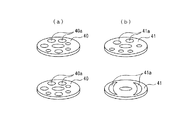
また、上記外筒30の周面及び内筒31の周面には、図15に示すように、それぞれ複数の開口30a、31aが設けられている。その複数の開口30a、31aの形状、大きさ、位置など調整することで、初期位置からの回動変位によって、両開口30a、31aの重なり合う穴及び重なり量が変更されることで、例えば図16に示すように、回動変位に対する、中央室CRと上部室UR及び下部室LRとのそれぞれに連通する開口面積が所定の関係に設定する。なお、図16は伸び側の関係のみを表示している。
The
Further, as shown in FIG. 15, a plurality of
次に、本実施形態の動作や作用・効果について説明する。
ピストン2が移動すると、そのストローク速度によって羽根車からなる区画板8に回転力が発生し、トーションバー21の捻れと釣り合う位置までバルブロッド20及び内筒31が回動変位する。これによって、ピストン2のストローク速度に応じた開口面積で、中央室CRを介して、上部室URと下部室LRとが連通して開口面積に応じて減衰抵抗が小さくなる。
Next, the operation, action, and effect of this embodiment will be described.
When the
また、上述のように回転角度に応じて連通する上記開口面積が変化するように設定されているので、理想の減衰力特性に近づくように減衰力特性を調整することができる。たとえば、図17のようにな特性となり、上述の図13の減衰力特性に近づくように調整される。
また、中央室CRと上部室URとの間に圧力差が無くなっても、また、第1下部室LR1と中央室CRとの間に圧力差が無くなっても、第1下部室LR1及び第2下部室LR2間に圧力差が有る限り、つまりピストン2が移動している限り、その圧力差で回転角度が決まり、それに応じた開口面積が確保されて上述のように必要な減衰力が確保できる。
In addition, as described above, since the opening area communicating with the rotation angle is set to change, the damping force characteristic can be adjusted so as to approach the ideal damping force characteristic. For example, the characteristic is as shown in FIG. 17 and is adjusted to approach the damping force characteristic of FIG. 13 described above.
Further, even if there is no pressure difference between the central chamber CR and the upper chamber UR, and even if there is no pressure difference between the first lower chamber LR1 and the central chamber CR, the first lower chamber LR1 and the second chamber LR1. As long as there is a pressure difference between the lower chambers LR2, that is, as long as the
また、開口位置、開口面積、開口形状、開口の数を調整すれば、回転角度に対する開口面積が多段階若しくはできるだけ滑らかに変更されるように設定することができるので、減衰力の変化率を滑らかにすることも可能である。したがって、急激な減衰力変化することによる反力発生による乗り心地の悪化を緩和することができる。
開口の別例を図18,図19に示す。
ここで、バウンド・リバウンドで最適な減衰力特性が異なることに鑑み、ピストン2のストローク方向(区画板8の回転方向)で回転角度に対する開口面積が異なるように設定している。
Also, by adjusting the aperture position, aperture area, aperture shape, and number of apertures, the aperture area with respect to the rotation angle can be set to be changed in multiple steps or as smoothly as possible. It is also possible to make it. Therefore, it is possible to mitigate the deterioration of riding comfort due to the generation of reaction force due to a sudden change in damping force.
Another example of the opening is shown in FIGS.
Here, considering that the optimum damping force characteristics are different between bound and rebound, the opening area with respect to the rotation angle is set to be different in the stroke direction of the piston 2 (the rotation direction of the partition plate 8).
ここで、ピストンロッド3の伸び・縮みに応じて、中央室CRに対する流入側の開口面積が、常に相対的に、中央室CRに対する流出側の開口面積となるように設定すれば、確実に圧力差を確保することができる。すわわち、伸び側では、上部室URから下部室にLR向けて流体が移動するので、上部室URと中央室CRとの間の開口面積が、中央室CRと下部室LRとの間の開口面積よりも常に大きくなるように設定すると良い。また、縮み側では、下部室LRから上部室URに向けて流体が移動するので、下部室LRと中央室CRとの間の開口面積が、中央室CRと上部室URとの間の開口面積よりも常に大きくなるように設定すると良い。
Here, if the opening area on the inflow side with respect to the central chamber CR is always set relatively to the opening area on the outflow side with respect to the central chamber CR in accordance with the expansion / contraction of the
なお、上記実施形態では、外筒30をピストン4側に、内筒31を区画板8側に連結しているが、外筒30を区画板8側に内筒31をピストン4側に連結しても良い。
また、上記実施形態では、外筒30と内筒31との開口を形成する面を周面に設定しているが、例えば、両筒30,31を共に上面及び下面を閉じたものとし、その上面及び下面に対して重なり合うことが可能な開口を形成するようにしても良い。
In the above embodiment, the
Moreover, in the said embodiment, although the surface which forms the opening of the
次に、第4実施形態について図面を参照しつつ説明する。なお、上記各実施形態と同様な部品などについては同一の符号を付して説明する。
本実施形態では、第3実施形態における内筒31及び外筒30の代わりに、図20のように、ピストン2の両側面に対し、それぞれ一対のディスク40,41を配置して第2調整弁としている。なお、上記各ディスク40,41は円板形状に限定されず、扇状などであっても良い。要は、互いの開口を閉塞したり開口したりする重なり部分が有ればよい。
Next, a fourth embodiment will be described with reference to the drawings. In addition, about the components similar to said each embodiment, the same code | symbol is attached | subjected and demonstrated.
In the present embodiment, instead of the
また、上記ピストン2を挟んで配置される2つのディスク40,41間に配置されるピストン2部分には、大きな開口が形成されて中央室CRが形成されている。
また、各一対のディスク40,41は、一方40がピストンロッド3に固定されると共に、他方41が上記バルブロッド20に固定されている。ここで、最大回動変位量を例えば±45度に設定すれば、その角度範囲で回動変位可能状態となるようにバルブロッド20と連結していれば良いので、上部室UR側にバルブロッド20に固定されるディスク41を設けても固定側のディスク40の共回りなどは防止可能である。
In addition, a large opening is formed in the
Each pair of
そして、各一対のディスク40,41において、図21に示すように、両ディスク40、41に開口が形成され、初期値位置からのディスク41の回転によって両ディスク40,41の開口の重なりが調整されて開口面積が変化する。この回転角度に対する開口面積を、ストローク速度に対する、目的の減衰力特性に応じて調整することで、上記第3実施形態と同様な効果を奏する。
図22にディスク40,41に設ける開口の別の例を示す。
その他の構成や作用効果は上記実施形態と同様である。
In each pair of
FIG. 22 shows another example of openings provided in the
Other configurations and operational effects are the same as in the above embodiment.
次に、第4実施形態について説明する。なお、上記各実施形態と同様な部品などについては同一の符号を付して説明する。
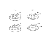
本実施形態では、図23に示すように、ピストン2に上部室URと下部室LR間を連通する複数の連通孔45を形成し、その連通孔45が開口する一方のピストン2の面に対向させてディスク41を配置し、該ディスク41を上記バルブロッド20に連結して、当該バルブロッド20と一体になって回転自在に構成したものである。そして、ピストン2及びディスク41に、図24に示すようように、複数の開口45,41aを設け、ピストン2の開口とディスク41の開口45,41aとの重なりをディスク41の回転角度で目的の開口面積となるように、開口45,41aの位置や大きさ形状などを調整する。
Next, a fourth embodiment will be described. In addition, about the components similar to said each embodiment, the same code | symbol is attached | subjected and demonstrated.
In the present embodiment, as shown in FIG. 23, the
図25に開口45,41aの別の例を示す。
本実施形態では、中央室CRが形成されない点を除けば上記第4実施形態と同様な作用・効果を発揮する。
ここで、上記実施形態では、区画部材である区画板8を下部室LRに配した場合を例示しているが、上部室URに区画板を配置して、上部室を2つの室に区画しても良い。
FIG. 25 shows another example of the
In the present embodiment, operations and effects similar to those of the fourth embodiment are exhibited except that the central chamber CR is not formed.
Here, in the said embodiment, although the case where the
また、上記実施形態では、第2調整弁は、軸方向への移動(スプールを使用したもの)若しくは回動変位するもの(バルブロッドを使用したもの)を例示しているが、両者すなわち、軸方向への移動によっても回動変位によっても弁の開度が変更するような構成になっていても良い。
さらに、上記第3〜第4実施形態では、回動変位によって弁の開度を調整する場合を例示しているが、軸方向への変位によって弁の開度を調整するように設定しても良い。例えば、第3実施形態において、外筒に対し内筒を軸方向へ変位することで開口の重なりが変更するように設定しても良い。なお、この場合には、第3の室である中央室CRの容積が変動することとなる。
Moreover, in the said embodiment, although the 2nd adjustment valve illustrated the movement to the axial direction (thing using a spool) or the thing to which it rotationally displaces (thing using a valve rod), both, ie, shaft The opening of the valve may be changed by movement in the direction or by rotational displacement.
Furthermore, although the case where the opening degree of the valve is adjusted by the rotational displacement is illustrated in the third to fourth embodiments, the opening degree of the valve may be adjusted by adjusting the displacement in the axial direction. good. For example, in the third embodiment, the overlapping of the openings may be changed by displacing the inner cylinder in the axial direction with respect to the outer cylinder. In this case, the volume of the central chamber CR that is the third chamber fluctuates.
UR 上部室
LR 下部室
LR1 第1下部室
LR2 第2下部室
CR 中央室
1 シリンダ
2 ピストン
3 ピストンロッド
4 第1連通路
5 リリーフ弁
6 スリーブ孔
7 スプール
8 区画板
8a 羽根板
10 バネ部材
12 第2連通路
13 下側連通孔
14 上側連通孔
20 バルブロッド
21 弾性体
30 外筒
30a 開口
31 内筒
31a 開口
40 ディスク(固定側)
40a 開口
41 ディスク(回転側)
41a 開口
45 開口
UR Upper chamber LR Lower chamber LR1 First lower chamber LR2 Second lower chamber
41a opening 45 opening
Claims (9)
上記ピストンで画成される2室を連通する連通路と、上記2つの室のうちの一方の室に配置されて上記ピストンに連動して進退する区画部材と、を備え、その区画部材の進退速度に応じて上記連通路の開口面積が調整されることを特徴とするショックアブソーバ。 In a shock absorber comprising a cylinder, a piston defining the inside of the cylinder in two chambers, and a piston rod connected to the piston and extending to the outside of the cylinder,
A communication passage that communicates the two chambers defined by the piston, and a partition member that is disposed in one of the two chambers and that moves forward and backward in conjunction with the piston. A shock absorber, wherein an opening area of the communication path is adjusted according to speed.
上記2室のうちの一方の室に配置されて当該一方の室を軸方向に並ぶ2つの室に区画する区画部材と、上記ピストンで画成された2室を連通する連通路と、上記連通路の開度を、上記区画部材で区画された2つの室間の圧力差に応じて調整する減衰力調整弁と、を備えることを特徴とするショックアブソーバ。 In a shock absorber comprising a cylinder, a piston defining the inside of the cylinder in two chambers, and a piston rod connected to the piston and extending to the outside of the cylinder,
A partition member that is disposed in one of the two chambers and divides the one chamber into two chambers arranged in the axial direction, a communication passage that connects the two chambers defined by the piston, and the communication A shock absorber, comprising: a damping force adjusting valve that adjusts an opening degree of the passage according to a pressure difference between the two chambers partitioned by the partition member.
上記区画部材は、上記第1及び第2の室の圧力差により回転し該回転を回動部材に伝達する羽根部材を備えることを特徴とする請求項2又は請求項3に記載したショックアブソーバ。 The damping force adjusting valve includes a rotating member coupled to the partition member and capable of rotating at least relative to the piston, and a spring member for biasing a circumferential position of the rotating member relative to the piston to an initial position. The opening degree of the communication path is adjusted by the rotational displacement of the rotating member,
The shock absorber according to claim 2 or 3, wherein the partition member includes a blade member that rotates due to a pressure difference between the first and second chambers and transmits the rotation to the rotating member.
Priority Applications (1)
| Application Number | Priority Date | Filing Date | Title |
|---|---|---|---|
| JP2005112185A JP2006292041A (en) | 2005-04-08 | 2005-04-08 | Shock absorber |
Applications Claiming Priority (1)
| Application Number | Priority Date | Filing Date | Title |
|---|---|---|---|
| JP2005112185A JP2006292041A (en) | 2005-04-08 | 2005-04-08 | Shock absorber |
Publications (1)
| Publication Number | Publication Date |
|---|---|
| JP2006292041A true JP2006292041A (en) | 2006-10-26 |
Family
ID=37412812
Family Applications (1)
| Application Number | Title | Priority Date | Filing Date |
|---|---|---|---|
| JP2005112185A Pending JP2006292041A (en) | 2005-04-08 | 2005-04-08 | Shock absorber |
Country Status (1)
| Country | Link |
|---|---|
| JP (1) | JP2006292041A (en) |
Cited By (8)
| Publication number | Priority date | Publication date | Assignee | Title |
|---|---|---|---|---|
| JP2008115913A (en) * | 2006-11-01 | 2008-05-22 | Miwa Lock Co Ltd | Spring damper |
| JP2010151301A (en) * | 2008-11-28 | 2010-07-08 | Honda Motor Co Ltd | Damping force variable damper |
| JP2011116468A (en) * | 2009-11-30 | 2011-06-16 | Mitsui Eng & Shipbuild Co Ltd | Quay crane and method of controlling the same |
| WO2011071120A1 (en) * | 2009-12-11 | 2011-06-16 | カヤバ工業株式会社 | Shock-absorbing device |
| JP2011122676A (en) * | 2009-12-11 | 2011-06-23 | Kyb Co Ltd | Shock absorbing device |
| KR101316458B1 (en) | 2007-10-29 | 2013-10-14 | 현대자동차주식회사 | Damper device |
| JP2019027563A (en) * | 2017-08-03 | 2019-02-21 | アイシン精機株式会社 | valve |
| JP2020180691A (en) * | 2019-04-26 | 2020-11-05 | トヨタ自動車株式会社 | Spool valve type shock absorber |
-
2005
- 2005-04-08 JP JP2005112185A patent/JP2006292041A/en active Pending
Cited By (13)
| Publication number | Priority date | Publication date | Assignee | Title |
|---|---|---|---|---|
| JP2008115913A (en) * | 2006-11-01 | 2008-05-22 | Miwa Lock Co Ltd | Spring damper |
| KR101316458B1 (en) | 2007-10-29 | 2013-10-14 | 현대자동차주식회사 | Damper device |
| JP4729110B2 (en) * | 2008-11-28 | 2011-07-20 | 本田技研工業株式会社 | Variable damping force damper |
| JP2010151301A (en) * | 2008-11-28 | 2010-07-08 | Honda Motor Co Ltd | Damping force variable damper |
| JP2011116468A (en) * | 2009-11-30 | 2011-06-16 | Mitsui Eng & Shipbuild Co Ltd | Quay crane and method of controlling the same |
| CN102686903A (en) * | 2009-12-11 | 2012-09-19 | 萱场工业株式会社 | Shock-absorbing device |
| JP2011122676A (en) * | 2009-12-11 | 2011-06-23 | Kyb Co Ltd | Shock absorbing device |
| WO2011071120A1 (en) * | 2009-12-11 | 2011-06-16 | カヤバ工業株式会社 | Shock-absorbing device |
| CN102686903B (en) * | 2009-12-11 | 2014-09-17 | 萱场工业株式会社 | Shock-absorbing device |
| US9435394B2 (en) | 2009-12-11 | 2016-09-06 | Kyb Corporation | Damping device |
| JP2019027563A (en) * | 2017-08-03 | 2019-02-21 | アイシン精機株式会社 | valve |
| JP2020180691A (en) * | 2019-04-26 | 2020-11-05 | トヨタ自動車株式会社 | Spool valve type shock absorber |
| JP7054063B2 (en) | 2019-04-26 | 2022-04-13 | トヨタ自動車株式会社 | Spool valve type shock absorber |
Similar Documents
| Publication | Publication Date | Title |
|---|---|---|
| JP2006292041A (en) | Shock absorber | |
| US6394240B1 (en) | Vehicle roll damping | |
| US8651252B2 (en) | Shock absorber | |
| JP6325074B2 (en) | Piston assembly with open bleed | |
| KR101946642B1 (en) | Damping force adjustable type damper | |
| JP2007536484A (en) | Air spring | |
| JP2010023528A (en) | Variable rigidity type stabilizer device | |
| US20120252590A1 (en) | Rotary damper | |
| WO2014024765A1 (en) | Valve and damper | |
| JP2013133896A (en) | Damping force adjustment type shock absorber | |
| JP4663379B2 (en) | Hydraulic shock absorber for vehicles | |
| GB2482855A (en) | A suspension unit for use on a tracked vehicle | |
| JPH0434236A (en) | Damping force variable shock absorber | |
| JP2004257507A (en) | Hydraulic damper | |
| US11649873B1 (en) | User-adjustable multi-stage shock absorbers | |
| US11623712B2 (en) | External damping adjustment apparatus and method for suspension system | |
| JP2020519520A (en) | Shock absorber with bidirectional selection block, wheel groove and motorcycle | |
| JP4955610B2 (en) | Rotary valve | |
| JP7269899B2 (en) | damping force adjustable shock absorber | |
| NO322224B1 (en) | Device for attenuating the pivotal movement of a wheel-bearing pendulum arm of a motor vehicle | |
| JP4229377B2 (en) | Shock absorber | |
| JP2012066644A (en) | Pedal device | |
| JP5057393B2 (en) | Rotary valve | |
| JPS61157848A (en) | Fluid pressure damper for car | |
| US20030192756A1 (en) | Rotary cam backup washer for disc valve adjustment |