JP2006283285A - Tunnel joining method - Google Patents

Tunnel joining method Download PDF

Info

Publication number
JP2006283285A
JP2006283285A JP2005101010A JP2005101010A JP2006283285A JP 2006283285 A JP2006283285 A JP 2006283285A JP 2005101010 A JP2005101010 A JP 2005101010A JP 2005101010 A JP2005101010 A JP 2005101010A JP 2006283285 A JP2006283285 A JP 2006283285A
Authority
JP
Japan
Prior art keywords
tunnel
segment
plate
connecting portion
fixed
Prior art date
Legal status (The legal status is an assumption and is not a legal conclusion. Google has not performed a legal analysis and makes no representation as to the accuracy of the status listed.)
Granted
Application number
JP2005101010A
Other languages
Japanese (ja)
Other versions
JP4627209B2 (en
Inventor
Kunihiro Nagamori
邦博 永森
Kosuke Furuichi
耕輔 古市
Masayoshi Nakagawa
雅由 中川
Takuro Kosaka
琢郎 小坂
Masaru Ushigaki
勝 牛垣
Current Assignee (The listed assignees may be inaccurate. Google has not performed a legal analysis and makes no representation or warranty as to the accuracy of the list.)
Kajima Corp
Original Assignee
Kajima Corp
Priority date (The priority date is an assumption and is not a legal conclusion. Google has not performed a legal analysis and makes no representation as to the accuracy of the date listed.)
Filing date
Publication date
Application filed by Kajima Corp filed Critical Kajima Corp
Priority to JP2005101010A priority Critical patent/JP4627209B2/en
Publication of JP2006283285A publication Critical patent/JP2006283285A/en
Application granted granted Critical
Publication of JP4627209B2 publication Critical patent/JP4627209B2/en
Expired - Fee Related legal-status Critical Current
Anticipated expiration legal-status Critical

Links

Images

Abstract

<P>PROBLEM TO BE SOLVED: To provide a tunnel joining method reducing a removal range of a tunnel skeleton, a soil improving range and a tunnel site width. <P>SOLUTION: In joining the upper half parts of a main tunnel 1 and a ramp tunnel 3, skin plates of segments 13a, 13b out of facing segments of the main tunnel 1 and ramp tunnel 3 are removed first to excavate an excavated part 17a between the main tunnel 1 and ramp tunnel 3. The remaining parts of the segments 13a, 13b are removed to install a connection part 19a between the segment 25 of the main tunnel 1 and the segment 31 of the ramp tunnel 3. The connection part 19a has a frame member 27 with one end fixed to the segment 25; H-shape steel 29 with the other end fixed to the segment 31; and axial reinforcing members 39 arranged in the axial direction of the tunnel between the adjacent H-shape steel 29. <P>COPYRIGHT: (C)2007,JPO&INPIT

Description

本発明は、トンネルの接合方法に関するものである。   The present invention relates to a tunnel joining method.

従来、地下道路や地下鉄道等のトンネルの分岐・合流部分を構築する際には、掘削断面形状を変更できるトンネル掘削機を用いて、拡幅部分を有するトンネルを構築する方法(例えば、特許文献1参照)、複数のトンネルを接合する方法(例えば、特許文献2参照)等が用いられている。   2. Description of the Related Art Conventionally, when constructing a branching / merging portion of a tunnel such as an underground road or a subway, a method of constructing a tunnel having a widened portion by using a tunnel excavator that can change a sectional shape of excavation (for example, Patent Document 1) And a method of joining a plurality of tunnels (for example, see Patent Document 2).

特開2004−68333号公報JP 2004-68333 A 特開2004−353264号公報JP 2004-353264 A

しかしながら、複数のトンネルを接合する場合、接合したい部分が離れていると、構造物の躯体を大幅に撤去し、大きな接合部材を再構築することとなる。さらに、周囲の地盤を広範囲にわたって改良する必要が生じる場合があるが、地盤改良や凍結工法などの補助工法を多用すると、工費や工期に加え、安全性の面で課題が残る。   However, when joining a plurality of tunnels, if the parts to be joined are separated from each other, the housing of the structure is largely removed, and a large joining member is reconstructed. Furthermore, there are cases where it is necessary to improve the surrounding ground over a wide range, but if auxiliary methods such as ground improvement and freezing methods are frequently used, problems remain in terms of safety in addition to construction cost and construction period.

本発明は、このような問題に鑑みてなされたもので、その目的とするところは、トンネルの躯体の撤去範囲や地盤改良の範囲、トンネル用地幅を縮小できるトンネルの接合方法を提供することにある。   The present invention has been made in view of such a problem, and an object of the present invention is to provide a tunnel joining method capable of reducing the tunnel housing removal range, ground improvement range, and tunnel ground width. is there.

前述した目的を達成するための本発明は、第1のトンネルおよび第2のトンネルを構築する工程(a)と、前記第1のトンネルおよび前記第2のトンネルの対向するセグメントのうち、上半部または下半部の所定のセグメントのスキンプレートを撤去して前記第1のトンネルと前記第2のトンネルとの間の地盤を掘削する工程(b)と、前記第1のトンネルと前記第2のトンネルとを接続する接続部を設置する工程(c)と、を具備することを特徴とするトンネルの接合方法である。   In order to achieve the above-mentioned object, the present invention includes a step (a) of constructing a first tunnel and a second tunnel, and an upper half of the segments facing each other of the first tunnel and the second tunnel. (B) excavating the ground between the first tunnel and the second tunnel by removing the skin plate of the predetermined segment of the part or the lower half, and the first tunnel and the second And a step (c) of providing a connecting portion for connecting to the other tunnel.

工程(c)で設置される接続部は、例えば、以下の6種類の形式のいずれかとする。第1の形式の接続部は、一端が第1のトンネルに固定されたコマ材と、一端がコマ材に、他端が第2のトンネルに固定された棒状の鋼材とからなる。コマ材は、短ボルト継手を用いて第2のトンネルに固定される。   The connection part installed in the step (c) is, for example, one of the following six types. The connection portion of the first type is composed of a piece of material having one end fixed to the first tunnel, and a rod-shaped steel material having one end fixed to the piece and the other end fixed to the second tunnel. The top material is fixed to the second tunnel using a short bolt joint.

第2の形式の接続部は、一端が第1のトンネルに固定されたコマ材と、一端がコマ材に、他端が第2のトンネルに固定された棒状の鋼材とからなる。コマ材は、長ボルト継手を用いて第2のトンネルに固定される。   The second type connecting portion is composed of a piece of material having one end fixed to the first tunnel, and a rod-shaped steel material having one end fixed to the piece and the other end fixed to the second tunnel. The top material is fixed to the second tunnel using a long bolt joint.

第3の形式の接続部は、一端が第1のトンネルに固定されたコマ材と、一端がコマ材に、他端が第2のトンネルに固定された棒状の鋼材と、コマ材と棒状の鋼材との間に固定されたヒンジ継手とからなる。   The connection part of the third type includes a piece of material having one end fixed to the first tunnel, a bar-shaped steel material having one end fixed to the frame, and the other end fixed to the second tunnel, It consists of a hinge joint fixed between steel materials.

第4の形式の接続部は、一端が第1のトンネルに固定された2枚の板状材と、一端が第2のトンネルに固定され、他端が2枚の板状材の間に配置された棒状の鋼材と、2枚の板状材の間に充填されたモルタルまたはコンクリートとからなる。   The connection part of the 4th type is arranged between two plate-like materials whose one end is fixed to the first tunnel, one end is fixed to the second tunnel, and the other end is between the two plate-like materials. And made of mortar or concrete filled between two plate-like materials.

第5の形式の接続部は、内側部材の一端が第1のトンネルに固定され、外側部材の一端が前記第2のトンネルに固定された可変式セグメントからなる。可変式セグメントは、外側部材に対して内側部材をスライドさせることにより、長さ調整が可能である。   A fifth type of connection comprises a variable segment with one end of the inner member secured to the first tunnel and one end of the outer member secured to the second tunnel. The variable segment can be adjusted in length by sliding the inner member relative to the outer member.

第6の形式の接続部は、一端が第1のトンネルを構成する第1のセグメント内に配置され、他端が第2のトンネルを構成する第2のセグメント内に配置された鉄筋と、第1のセグメントおよび第2のセグメントの内側面に、鉄筋に平行または垂直に固定された板状部材と、鉄筋の周囲に設置されたコンクリートとからなる。板状部材には、必要に応じて、鉄筋を通すための穴や、コンクリートの充填性を高めるための切欠き部が設けられる。   The connection portion of the sixth type has a reinforcing bar arranged at one end in the first segment constituting the first tunnel and at the other end in the second segment constituting the second tunnel, It consists of the plate-shaped member fixed to the internal surface of 1 segment and the 2nd segment in parallel or perpendicular | vertical to a reinforcing bar, and the concrete installed around the reinforcing bar. The plate-like member is provided with a hole for passing a reinforcing bar and a notch for enhancing the filling property of concrete as necessary.

工程(a)で、構築される第1のトンネルは、例えば、周方向の断面がほぼD字型の本線トンネルであり、第2のトンネルは、周方向の断面が円形等のランプトンネルである。工程(c)では、工程(c)では、工程(b)でスキンプレートを撤去したセグメントの主桁の間を通るように、接続部を設置する。または、工程(b)でスキンプレートを撤去したセグメントの残りの部分の全体または一部(セグメントの主桁等)を撤去して、接続部を設置する。本発明では、接続部のトンネル内周側にトラス材を設置する工程(d)をさらに設けてもよい。   The first tunnel constructed in the step (a) is, for example, a main tunnel having a substantially D-shaped circumferential section, and the second tunnel is a lamp tunnel having a circular section in the circumferential direction. . In the step (c), in the step (c), the connecting portion is installed so as to pass between the main beams of the segment from which the skin plate has been removed in the step (b). Alternatively, the whole or a part of the remaining part of the segment from which the skin plate has been removed in the step (b) (such as the main girder of the segment) is removed, and the connecting portion is installed. In this invention, you may further provide the process (d) which installs a truss material in the tunnel inner peripheral side of a connection part.

本発明によれば、トンネルの躯体の撤去範囲や地盤改良の範囲、トンネル用地幅を縮小できるトンネルの接合方法を提供できる。   ADVANTAGE OF THE INVENTION According to this invention, the joining method of the tunnel which can reduce the removal range of a tunnel frame, the range of ground improvement, and the tunnel ground width can be provided.

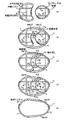
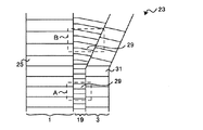
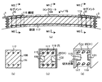
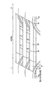
以下、図面に基づいて、本発明の第1の実施の形態について詳細に説明する。図1は、本線トンネル1とランプトンネル3を接続して合成トンネル23を形成するための各工程を示す図、図2は、合成トンネル23を上方から見た図である。図1に示すように、本線トンネル1は、地盤11内に設置され、周方向の断面がほぼD字型である。ランプトンネル3は、地盤11内に設置され、周方向の断面が円形である。合成トンネル23の形成部分において、本線トンネル1とランプトンネル3との間隔は、図2に示すように、徐々に変化する。   Hereinafter, a first embodiment of the present invention will be described in detail with reference to the drawings. FIG. 1 is a view showing each process for forming the composite tunnel 23 by connecting the main tunnel 1 and the lamp tunnel 3, and FIG. 2 is a view of the composite tunnel 23 as viewed from above. As shown in FIG. 1, the main tunnel 1 is installed in the ground 11 and has a substantially D-shaped circumferential section. The lamp tunnel 3 is installed in the ground 11 and has a circular cross section in the circumferential direction. In the formation portion of the synthetic tunnel 23, the distance between the main tunnel 1 and the lamp tunnel 3 gradually changes as shown in FIG.

第1の実施の形態では、本線トンネル1とランプトンネル3とを接合する方法について説明する。図1の(a)図は、本線トンネル1とランプトンネル3の内部に支保工を設置する工程を示す。図1の(a)図では、まず、本線トンネル1の内部に鉛直方向支保工5aを、ランプトンネル3の内部に鉛直方向支保工5bを設置する。また、本線トンネル1の内部に水平方向支保工7aを、ランプトンネル3の内部に水平方向支保工7bを設置する。   In the first embodiment, a method of joining the main tunnel 1 and the lamp tunnel 3 will be described. FIG. 1A shows a process of installing a supporting work inside the main tunnel 1 and the ramp tunnel 3. In FIG. 1A, first, a vertical support 5 a is installed inside the main tunnel 1, and a vertical support 5 b is installed inside the ramp tunnel 3. Further, a horizontal support 7 a is installed inside the main tunnel 1 and a horizontal support 7 b is installed inside the ramp tunnel 3.

図1の(b)図は、地盤11の掘削部17aを掘削する工程を示す。図1の(a)図に示すように支保工を設置した後、図1の(b)図に示すように、本線トンネル1およびランプトンネル3の上方・下方の地盤11に、凍結工法等を用いて地盤改良9を行う。そして、本線トンネル1の上半部のセグメント13aのスキンプレート、ランプトンネル3の上半部のセグメント13bのスキンプレートを撤去し、本線トンネル1とランプトンネル3の間の掘削部17aを掘削して、掘削部17aに支保工15aを設置する。なお、図1、図14、図18において、セグメント13の点線部分は、スキンプレートが撤去された状態であることを示す。   FIG. 1B shows a process of excavating the excavation part 17 a of the ground 11. After the support is installed as shown in FIG. 1 (a), the freezing method is applied to the ground 11 above and below the main tunnel 1 and the ramp tunnel 3 as shown in FIG. 1 (b). Use to improve the ground. Then, the skin plate of the segment 13a in the upper half of the main tunnel 1 and the skin plate of the segment 13b in the upper half of the ramp tunnel 3 are removed, and the excavation part 17a between the main tunnel 1 and the ramp tunnel 3 is excavated. The support work 15a is installed in the excavation part 17a. 1, 14, and 18, the dotted line portion of the segment 13 indicates that the skin plate has been removed.

図1の(c)図は、接続部19aを設置して掘削部17bを掘削する工程を示す。図1の(c)図では、図1の(b)図でスキンプレートを撤去した本線トンネル1の上半部のセグメント13aとランプトンネル3の上半部のセグメント13bの残りの部分(桁等)を撤去する。次に、本線トンネル1とランプトンネル3の上半部同士を連結する接続部19aを設置する。接続部19aの詳細な構造については後述する。接続部19aを設置した後、接続部19aの外周側に位置する掘削部17aの埋め戻し21を行う。埋め戻し21は、現地発生土やモルタル等の埋め戻し材を用いて行う。   FIG. 1C illustrates a process of excavating the excavation part 17b by installing the connection part 19a. In FIG. 1 (c), the remaining portion (girder, etc.) of the segment 13a in the upper half of the main tunnel 1 and the segment 13b in the upper half of the ramp tunnel 3 with the skin plate removed in FIG. 1 (b). ). Next, a connecting portion 19 a that connects the upper half portions of the main tunnel 1 and the lamp tunnel 3 is installed. The detailed structure of the connecting portion 19a will be described later. After the connection part 19a is installed, the excavation part 17a located on the outer peripheral side of the connection part 19a is backfilled 21. The backfill 21 is performed using a backfill material such as locally generated soil or mortar.

図1の(c)図では、さらに、本線トンネル1のランプトンネル3と対向する側部のセグメント14aのスキンプレート、ランプトンネル3の本線トンネル1と対向する側部のセグメント14bのスキンプレートをそれぞれ撤去し、掘削部17aの下方の掘削部17bを掘削して、掘削部17bに支保工15bを設置する。   In FIG. 1C, the skin plate of the side segment 14a of the main tunnel 1 facing the lamp tunnel 3 and the skin plate of the side segment 14b of the lamp tunnel 3 facing the main tunnel 1 are respectively shown. The excavation part 17b below the excavation part 17a is excavated, and the support work 15b is installed in the excavation part 17b.

なお、図1の(b)図に示す工程で地盤改良9に凍結工法を用いた場合には、埋め戻し21を行った後の適切な時期に、本線トンネル1およびランプトンネル3の上方の地盤11の凍結を解除する。   When the freezing method is used for the ground improvement 9 in the process shown in FIG. 1B, the ground above the main tunnel 1 and the ramp tunnel 3 at an appropriate time after the backfill 21 is performed. 11 freezing is released.

図1の(d)図は、掘削部17cを掘削する工程を示す図である。図1の(d)図では、本線トンネル1の下半部のセグメント13cのスキンプレート、ランプトンネル3の下半部のセグメント13dのスキンプレートを撤去し、本線トンネル1とランプトンネル3の間の掘削部17cを掘削する。   FIG. 1D is a diagram showing a process of excavating the excavation part 17c. In FIG. 1D, the skin plate of the segment 13c in the lower half of the main tunnel 1 and the skin plate of the segment 13d in the lower half of the ramp tunnel 3 are removed, and the space between the main tunnel 1 and the ramp tunnel 3 is removed. Excavation part 17c is excavated.

図1の(e)図は、接続部19bを設置して合成トンネル23を完成する工程を示す。図1の(e)図では、図1の(d)図でスキンプレートを撤去した本線トンネル1の下半部のセグメント13cとランプトンネル3の下半部のセグメント13dの残りの部分(桁等)を撤去する。次に、本線トンネル1とランプトンネル3の下半部同士を連結する接続部19bを設置する。   FIG. 1 (e) shows a process of installing the connecting portion 19b to complete the composite tunnel 23. FIG. In FIG. 1 (e), the remaining part (girder etc.) of the segment 13c in the lower half of the main tunnel 1 and the segment 13d in the lower half of the ramp tunnel 3 with the skin plate removed in FIG. 1 (d). ). Next, a connecting portion 19b that connects the lower half portions of the main tunnel 1 and the lamp tunnel 3 is installed.

図1の(e)図では、接続部19bを設置した後、接続部19bの外周側に位置する掘削部17cの埋め戻し(図示せず)を行う。そして、本線トンネル1のセグメント14aおよびランプトンネル3のセグメント14bの残りの部分、鉛直方向支保工5a、鉛直方向支保工5b、水平方向支保工7a、水平方向支保工7b、支保工15a、支保工15bを撤去して、合成トンネル23を完成する。   In FIG. 1 (e), after the connection portion 19b is installed, the excavation portion 17c located on the outer peripheral side of the connection portion 19b is backfilled (not shown). And the remaining part of the segment 14a of the main tunnel 1 and the segment 14b of the ramp tunnel 3, the vertical support 5a, the vertical support 5b, the horizontal support 7a, the horizontal support 7b, the support 15a, the support The synthetic tunnel 23 is completed by removing 15b.

なお、図1の(b)図に示す工程で地盤改良9に凍結工法を用いた場合には、埋め戻し(図示せず)を行った後、本線トンネル1およびランプトンネル3の下方の地盤11の凍結を解除する。   In addition, when the freezing method is used for the ground improvement 9 in the process shown in FIG. 1B, after the backfilling (not shown), the ground 11 below the main tunnel 1 and the ramp tunnel 3 is used. Unfreeze.

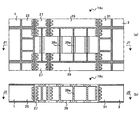
以下に、接続部19aの詳細な構造について述べる。図3は、接続部19a付近の斜視図、図4は、接続部19a付近の断面図を示す。図3、図4に示すように、接続部19aは、本線トンネル1のセグメント25の端面26と、ランプトンネル3のセグメント31の端面28との間に設置される。端面26、端面28は、セグメント25、セグメント31に補強材として新設する。または、セグメント25、セグメント31の継手板を端面26、端面28として用いてもよい。なお、図2に示すように、接続部19aの長さは、本線トンネル1とランプトンネル3の設置間隔によって変化する。   Below, the detailed structure of the connection part 19a is described. 3 is a perspective view of the vicinity of the connecting portion 19a, and FIG. 4 is a cross-sectional view of the vicinity of the connecting portion 19a. As shown in FIGS. 3 and 4, the connecting portion 19 a is installed between the end face 26 of the segment 25 of the main tunnel 1 and the end face 28 of the segment 31 of the lamp tunnel 3. The end face 26 and the end face 28 are newly provided as a reinforcing material in the segment 25 and the segment 31. Alternatively, joint plates of the segment 25 and the segment 31 may be used as the end surface 26 and the end surface 28. As shown in FIG. 2, the length of the connecting portion 19 a varies depending on the installation interval between the main tunnel 1 and the lamp tunnel 3.

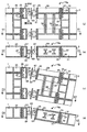
図4の(a)図は、図2のAに示す部分の水平方向の断面図を、図4の(b)図は、図2のAに示す部分の垂直方向の断面図を示す。図4の(a)図は、図4の(b)図のC2−C2による断面図、図4の(b)図は、図4の(a)図のC1−C1による断面図である。   4A is a horizontal sectional view of the portion shown in FIG. 2A, and FIG. 4B is a vertical sectional view of the portion shown in FIG. 4A is a cross-sectional view taken along C2-C2 in FIG. 4B, and FIG. 4B is a cross-sectional view taken along C1-C1 in FIG. 4A.

図3、図4の(a)図、図4の(b)図に示すように、接続部19aは、一端がセグメント25の端面26に固定されたコマ材27、一端がコマ材27の他端に固定され、他端がセグメント31の端面28に固定されたH型鋼29、隣り合う2本のH型鋼29の間の空間を補強する軸方向補強材39等からなる。コマ材27は、セグメント25のリング間の継手面の延長上に固定され、H型鋼29は、セグメント31のリング間の継手面の延長上に固定される。   As shown in FIGS. 3, 4A and 4B, the connecting portion 19a has a piece 27 of which one end is fixed to the end face 26 of the segment 25 and one end of the connecting piece 19a. An H-shaped steel 29 fixed to the end and the other end fixed to the end face 28 of the segment 31, an axial reinforcing material 39 that reinforces a space between two adjacent H-shaped steels 29, and the like. The top member 27 is fixed on the extension of the joint surface between the rings of the segment 25, and the H-shaped steel 29 is fixed on the extension of the joint surface between the rings of the segment 31.

図4の(a)図、図4の(b)図に示すように、コマ材27は、例えば、H型鋼の両端に継手板33を固定したものである。継手板33は、H型鋼の軸方向に垂直に固定される。H型鋼29は、H型鋼の両端に継手板35を固定したものである。継手板35は、H型鋼の軸方向に垂直に固定される。軸方向補強材39は、例えば、H型鋼である。   As shown in FIGS. 4A and 4B, the top member 27 is obtained by fixing joint plates 33 to both ends of H-shaped steel, for example. The joint plate 33 is fixed perpendicularly to the axial direction of the H-shaped steel. The H-shaped steel 29 is obtained by fixing joint plates 35 to both ends of the H-shaped steel. The joint plate 35 is fixed perpendicularly to the axial direction of the H-shaped steel. The axial reinforcing member 39 is, for example, H-shaped steel.

コマ材27の継手板33とセグメント35の端面26、コマ材27の継手板33とH型鋼29の継手板35、H型鋼29の継手板35とセグメント31の端面28は、それぞれ、短ボルトおよびナット37によって固定される。軸方向補強材39の一端は、H型鋼29の上下のフランジの間に挿入される。軸方向補強材39の他端は、隣り合う他のH型鋼29の上下のフランジの間に挿入される。軸方向補強材39の端部は、H型鋼29のウェブまたはフランジに固定される。   The joint plate 33 of the top member 27 and the end surface 26 of the segment 35, the joint plate 33 of the top member 27 and the joint plate 35 of the H-shaped steel 29, the joint plate 35 of the H-shaped steel 29 and the end surface 28 of the segment 31, respectively, It is fixed by the nut 37. One end of the axial reinforcing member 39 is inserted between the upper and lower flanges of the H-shaped steel 29. The other end of the axial reinforcing member 39 is inserted between the upper and lower flanges of another adjacent H-shaped steel 29. The end of the axial reinforcing member 39 is fixed to the web or flange of the H-shaped steel 29.

なお、図4では、H型鋼等の軸方向補強材39の端部をH型鋼29の上下のフランジの間に挿入したが、ウェブよりもフランジの方が長いH型鋼である軸方向補強材のフランジの端部を、H型鋼29の上下のフランジを挟み込むように配置し、H型鋼29のフランジと軸方向補強材のフランジとを固定してもよい。   In FIG. 4, the end portion of the axial reinforcing material 39 such as H-shaped steel is inserted between the upper and lower flanges of the H-shaped steel 29, but the axial reinforcing material is an H-shaped steel whose flange is longer than the web. The end of the flange may be disposed so as to sandwich the upper and lower flanges of the H-shaped steel 29, and the flange of the H-shaped steel 29 and the flange of the axial reinforcing material may be fixed.

図4の(c)図は、図2のBに示す部分の水平方向の断面図を、図4の(d)図は、図2のBに示す部分の垂直方向の断面図を示す。図4の(c)図は、図4の(d)図のC4−C4による断面図、図4の(d)図は、図4の(c)図のC3−C3による断面図である。   4C is a horizontal sectional view of the portion shown in FIG. 2B, and FIG. 4D is a vertical sectional view of the portion shown in FIG. 4C is a cross-sectional view taken along line C4-C4 in FIG. 4D, and FIG. 4D is a cross-sectional view taken along line C3-C3 in FIG. 4C.

図4の(c)図、図4の(d)図に示すように、図2のBに示す部分において、接続部19aの構成は、図2のAに示す部分とほぼ同様である。図2のBに示す部分の接続部19aでは、図2のAに示す部分の接続部19aのコマ材27の替わりに、コマ材27aと誤差吸収プレート41とが用いられる。   As shown in FIGS. 4C and 4D, in the portion shown in B of FIG. 2, the configuration of the connecting portion 19a is substantially the same as the portion shown in A of FIG. In the connection portion 19a shown in FIG. 2B, the piece material 27a and the error absorbing plate 41 are used instead of the piece material 27 of the connection portion 19a shown in FIG.

図4の(c)図、図4の(d)図に示すように、コマ材27aは、例えば、H型鋼の両端に継手板33aを固定したものである。片端の継手板33aはH型鋼の軸方向に垂直に、他端の継手板33aはH型鋼の軸方向と所定の角度を成して固定される。   As shown in FIGS. 4 (c) and 4 (d), the top member 27a has, for example, joint plates 33a fixed to both ends of an H-shaped steel. The joint plate 33a at one end is fixed perpendicularly to the axial direction of the H-shaped steel, and the joint plate 33a at the other end is fixed at a predetermined angle with the axial direction of the H-shaped steel.

コマ材27aの継手板33aとセグメント25の端面26とは、短ボルトおよびナット37によって固定される。コマ材27aの継手板33aとH型鋼29の継手板35とは、間に誤差吸収プレート41を挟んだ状態で、短ボルトおよびナット37によって固定される。   The joint plate 33 a of the top member 27 a and the end face 26 of the segment 25 are fixed by a short bolt and a nut 37. The joint plate 33a of the top member 27a and the joint plate 35 of the H-shaped steel 29 are fixed by short bolts and nuts 37 with the error absorbing plate 41 sandwiched therebetween.

図4に示すような接続部19aを形成するには、セグメント25とセグメント31との間に、コマ材27およびH型鋼29、または、コマ材27a、誤差吸収プレート41およびH型鋼29を設置する工程と、H型鋼29のフランジの間に軸方向補強材39の端部を挿入する工程とを、トンネル軸方向に順次繰り返す。そして、隣り合うH型鋼29の間にコンクリートまたはモルタル(図示せず)を充填する。   In order to form the connecting portion 19a as shown in FIG. 4, the piece material 27 and the H-shaped steel 29 or the piece material 27a, the error absorbing plate 41 and the H-shaped steel 29 are installed between the segment 25 and the segment 31. The step and the step of inserting the end portion of the axial reinforcing member 39 between the flanges of the H-shaped steel 29 are sequentially repeated in the tunnel axial direction. Then, concrete or mortar (not shown) is filled between the adjacent H-shaped steels 29.

接続部19aを形成する際には、コマ材27、コマ材27aの大きさを一定とし、本線トンネル1とランプトンネル3との間隔の変化に伴う接続部19aの長さの変化には、H型鋼29の長さを変化させて対応する。コマ材27aを用いる部分では、数種類の厚さの誤差吸収プレート41を準備しておき、適切な厚さの誤差吸収プレート41を用いることにより施工誤差を吸収する。   When forming the connecting portion 19a, the size of the top material 27 and the top material 27a is constant, and the change in the length of the connecting portion 19a accompanying the change in the distance between the main tunnel 1 and the lamp tunnel 3 includes H The length of the steel plate 29 is changed to cope with it. In the portion using the top material 27a, several types of error absorbing plates 41 having different thicknesses are prepared, and the construction error is absorbed by using the error absorbing plate 41 having an appropriate thickness.

第1の実施の形態では、図1に示す接続部19bも、接続部19aと同様の部材および方法で構成される。   In the first embodiment, the connecting portion 19b shown in FIG. 1 is also configured by the same members and methods as the connecting portion 19a.

このように、第1の実施の形態では、図1に示すような工程で本線トンネル1とランプトンネル3を接続することにより、合成トンネル23の形成時に、トンネルの躯体の撤去範囲や地盤改良の範囲、トンネル用地幅を縮小できる。また、図4に示すように、接続部19aを形成する際に、自重や曲げ剛性が比較的小さいH型鋼29等の鋼材を用いることにより、RC構造と比べて断面力を小さく抑えることが可能となる。図4に示す接続部19aでは、コマ材27や、コマ材27aと誤差吸収プレート41を用いた単純な構造で、ある程度の施工誤差に対処できる。   As described above, in the first embodiment, the main tunnel 1 and the ramp tunnel 3 are connected in the process shown in FIG. Range, tunnel width can be reduced. Moreover, as shown in FIG. 4, when forming the connection part 19a, it is possible to suppress the cross-sectional force to be smaller than that of the RC structure by using a steel material such as H-shaped steel 29 having a relatively low weight and bending rigidity. It becomes. In the connecting portion 19a shown in FIG. 4, it is possible to cope with a certain degree of construction error with a simple structure using the top material 27, the top material 27a and the error absorbing plate 41.

なお、第1の実施の形態では、接続部19を図4に示す接続部19aのような構造としたが、接続部19の構造は、これに限らない。   In the first embodiment, the connecting portion 19 has a structure like the connecting portion 19a shown in FIG. 4, but the structure of the connecting portion 19 is not limited to this.

図5は、他の構造の接続部19c付近の断面図である。図5の(a)図は、図2のAに示す部分の水平方向の断面図を、図5の(b)図は、図2のAに示す部分の垂直方向の断面図を示す。図5の(a)図は、図5の(b)図のJ2−J2による断面図、図5の(b)図は、図5の(a)図のJ1−J1による断面図である。   FIG. 5 is a cross-sectional view of the vicinity of the connecting portion 19c having another structure. 5A is a horizontal sectional view of the portion shown in FIG. 2A, and FIG. 5B is a vertical sectional view of the portion shown in FIG. 5A is a cross-sectional view taken along J2-J2 in FIG. 5B, and FIG. 5B is a cross-sectional view taken along J1-J1 in FIG. 5A.

図5に示す接続部19cは、図4に示す接続部19aとほぼ同様の構成であるが、軸方向補強材39の替わりに、軸方向補強材39aが用いられる。軸方向補強材39aは、隣り合う2本のH型鋼29や、隣り合う2個のコマ材27の間の空間を補強する。軸方向補強材39aは、例えば、ウェブがフランジより長いH型鋼である。軸方向補強材39aのウェブの両端は、H型鋼29やコマ材27の上下のフランジの間に挿入される。軸方向補強材39aのフランジやウェブの両端は、H型鋼29やコマ材27のフランジやウェブに固定される。   The connecting portion 19c shown in FIG. 5 has substantially the same configuration as the connecting portion 19a shown in FIG. 4, but an axial reinforcing member 39a is used instead of the axial reinforcing member 39. The axial reinforcing member 39a reinforces the space between the two adjacent H-shaped steels 29 and the two adjacent piece members 27. The axial reinforcing member 39a is, for example, an H-shaped steel whose web is longer than the flange. Both ends of the web of the axial reinforcing member 39 a are inserted between the upper and lower flanges of the H-shaped steel 29 and the piece member 27. Both ends of the flange and web of the axial reinforcing member 39a are fixed to the flange and web of the H-shaped steel 29 and the top member 27.

接続部19cでは、隣り合うH型鋼29、コマ材27の間にコンクリートまたはモルタル(図示せず)が充填される。
図5に示す接続部19cの構成は、図2のBに示す部分の接続部19aや、図1に示す接続部19bにおいても、適用することができる。
In the connecting portion 19 c, concrete or mortar (not shown) is filled between the adjacent H-shaped steel 29 and the piece material 27.
The configuration of the connecting portion 19c shown in FIG. 5 can also be applied to the connecting portion 19a in the portion shown in B of FIG. 2 and the connecting portion 19b shown in FIG.

図6は、他の構造の接続部19d付近の断面図である。図6の(a)図は、図2のAに示す部分の水平方向の断面図を、図6の(b)図は、図2のAに示す部分の垂直方向の断面図を示す。図6の(a)図は、図6の(b)図のK2−K2による断面図、図6の(b)図は、図6の(a)図のK1−K1による断面図である。   FIG. 6 is a cross-sectional view of the vicinity of the connecting portion 19d having another structure. 6A is a horizontal sectional view of the portion shown in FIG. 2A, and FIG. 6B is a vertical sectional view of the portion shown in FIG. 6A is a cross-sectional view taken along line K2-K2 in FIG. 6B, and FIG. 6B is a cross-sectional view taken along line K1-K1 in FIG. 6A.

図6に示す接続部19dは、図4に示す接続部19aとほぼ同様の構成であるが、軸方向補強材39の替わりに、プレート99が用いられる。プレート99は、隣り合う2本のH型鋼29や、隣り合う2個のコマ材27の間の空間を補強する。プレート99は、1枚の板材である。プレート99は、H型鋼29とコマ材27の上下のフランジの外側に、溶接等によって固定される。   The connecting portion 19d shown in FIG. 6 has substantially the same configuration as the connecting portion 19a shown in FIG. 4, but a plate 99 is used in place of the axial reinforcing member 39. The plate 99 reinforces the space between the two adjacent H-shaped steels 29 and the two adjacent frame members 27. The plate 99 is a single plate material. The plate 99 is fixed to the outside of the upper and lower flanges of the H-shaped steel 29 and the piece material 27 by welding or the like.

接続部19dでは、隣り合うH型鋼29、コマ材27の間にコンクリート(図示せず)が充填される。
図6に示す接続部19dの構成は、図2のBに示す部分の接続部19aや、図1に示す接続部19bにおいても、適用することができる。
In the connecting portion 19 d, concrete (not shown) is filled between the adjacent H-shaped steel 29 and the piece material 27.
The configuration of the connecting portion 19d shown in FIG. 6 can also be applied to the connecting portion 19a in the portion shown in B of FIG. 2 and the connecting portion 19b shown in FIG.

図7は、他の構造の接続部19e付近の断面図である。図7の(a)図は、図2のAに示す部分の水平方向の断面図を、図7の(b)図は、図2のAに示す部分の垂直方向の断面図を示す。図7の(a)図は、図7の(b)図のL2−L2による断面図、図7の(b)図は、図7の(a)図のL1−L1による断面図である。   FIG. 7 is a cross-sectional view of the vicinity of the connecting portion 19e having another structure. 7A shows a horizontal sectional view of the portion shown in FIG. 2A, and FIG. 7B shows a vertical sectional view of the portion shown in FIG. 7A is a cross-sectional view taken along line L2-L2 in FIG. 7B, and FIG. 7B is a cross-sectional view taken along line L1-L1 in FIG. 7A.

図7に示す接続部19eは、図4に示す接続部19aとほぼ同様の構成であるが、軸方向補強材39の替わりに、プレート101が用いられる。プレート101は、隣り合う2本のH型鋼29や、隣り合う2個のコマ材27の間の空間を補強する。プレート101は、棒状の板材である。接続部19eでは、複数のプレート101が、H型鋼29やコマ材27の上下のフランジの外側に、ボルトおよびナット103を用いて固定される。   The connection portion 19e shown in FIG. 7 has substantially the same configuration as the connection portion 19a shown in FIG. 4, but a plate 101 is used in place of the axial reinforcing member 39. The plate 101 reinforces the space between the two adjacent H-shaped steels 29 and the two adjacent frame members 27. The plate 101 is a rod-shaped plate material. In the connection portion 19 e, the plurality of plates 101 are fixed to the outside of the upper and lower flanges of the H-shaped steel 29 and the piece material 27 using bolts and nuts 103.

接続部19eでは、隣り合うH型鋼29、コマ材27の間にコンクリートまたはモルタル(図示せず)が充填される。
図7に示す接続部19cの構成は、図2のBに示す部分の接続部19aや、図1に示す接続部19bにおいても、適用することができる。
In the connecting portion 19e, concrete or mortar (not shown) is filled between the adjacent H-shaped steel 29 and the piece 27.
The configuration of the connecting portion 19c shown in FIG. 7 can also be applied to the connecting portion 19a in the portion shown in B of FIG. 2 and the connecting portion 19b shown in FIG.

接続部19を図5から図7に示すような構造とした場合にも、自重や曲げ剛性が比較的小さいH型鋼29等の鋼材を用いることにより、RC構造と比べて断面力を小さく抑えることが可能となる。また、コマ材27や、コマ材27aと誤差吸収プレート41を用いた単純な構造で、ある程度の施工誤差に対処できる。   Even when the connecting portion 19 has a structure as shown in FIGS. 5 to 7, by using a steel material such as H-shaped steel 29 having a relatively low self-weight and bending rigidity, the cross-sectional force can be suppressed smaller than that of the RC structure. Is possible. In addition, a simple structure using the top material 27, the top material 27a, and the error absorbing plate 41 can cope with a certain degree of construction error.

次に、第2の実施の形態について説明する。図8は、他の構造の接続部19f付近の断面図およびコマ材43の断面図を示す。第2の実施の形態では、第1の実施の形態と同様に、図1に示す各工程によって本線トンネル1とランプトンネル3とを接合するが、接続部19に、図4に示す接続部19aの替わりに、図8に示す接続部19fを用いる。   Next, a second embodiment will be described. FIG. 8 shows a cross-sectional view in the vicinity of the connecting portion 19 f of another structure and a cross-sectional view of the piece member 43. In the second embodiment, as in the first embodiment, the main tunnel 1 and the lamp tunnel 3 are joined by the steps shown in FIG. 1, but the connection 19 is connected to the connection 19a shown in FIG. Instead of this, a connecting portion 19f shown in FIG. 8 is used.

図8の(a)図は、図2のAに示す部分の水平方向の断面図を、図8の(b)図は、図2のAに示す部分の垂直方向の断面図を示す。図8の(a)図は、図8の(b)図のD2−D2による断面図、図8の(b)図は、図8の(a)図のD1−D1による断面図である。   8A shows a horizontal sectional view of the portion shown in FIG. 2A, and FIG. 8B shows a vertical sectional view of the portion shown in FIG. 8A is a cross-sectional view taken along D2-D2 in FIG. 8B, and FIG. 8B is a cross-sectional view taken along D1-D1 in FIG. 8A.

図8の(a)図、図8の(b)図に示すように、接続部19fは、一端がセグメント25の端面26に固定されたコマ材43、一端がコマ材43の他端に固定され、他端がセグメント31の端面28に固定されたH型鋼29、隣り合う2本のH型鋼29の間の空間を補強する軸方向補強材39等からなる。コマ材43は、セグメント25のリング間の継手面の延長上に固定され、H型鋼29は、セグメント31のリング間の継手面の延長上に固定される。   As shown in FIGS. 8A and 8B, the connecting portion 19f has a piece 43 fixed at one end to the end face 26 of the segment 25, and one fixed to the other end of the piece 43. The other end includes an H-shaped steel 29 fixed to the end surface 28 of the segment 31, an axial reinforcing material 39 that reinforces a space between two adjacent H-shaped steels 29, and the like. The top member 43 is fixed on the extension of the joint surface between the rings of the segment 25, and the H-shaped steel 29 is fixed on the extension of the joint surface between the rings of the segment 31.

図8の(a)図、図8の(b)図、図8の(c)図に示すように、H型鋼29は、H型鋼の両端に継手板35を固定したものである。継手板35は、H型鋼の軸方向に垂直に固定される。軸方向補強材39は、例えば、H型鋼である。   As shown in FIG. 8 (a), FIG. 8 (b), and FIG. 8 (c), the H-shaped steel 29 is obtained by fixing joint plates 35 to both ends of the H-shaped steel. The joint plate 35 is fixed perpendicularly to the axial direction of the H-shaped steel. The axial reinforcing member 39 is, for example, H-shaped steel.

図8の(c)図は、コマ材43の断面図を示す。図8の(a)図、図8の(b)図、図8の(c)図に示すように、コマ材43は、例えば、筒体49、筒体49a、継手板45、継手板45a、長ボルト47、球面ナット53、ナット51、モルタル55等からなる。   FIG. 8C shows a cross-sectional view of the piece material 43. 8 (a), FIG. 8 (b), and FIG. 8 (c), the top member 43 includes, for example, a cylindrical body 49, a cylindrical body 49a, a joint plate 45, and a joint plate 45a. , A long bolt 47, a spherical nut 53, a nut 51, a mortar 55, and the like.

筒体49、筒体49aは、断面が矩形である。継手板45は、セグメント25内に、端面26にほぼ平行に配置される。継手板45aは、筒体49と筒体49aの境界部に、セグメント25の端面26にほぼ平行に設置される。長ボルト47は、継手板45、セグメント25の端面26、継手板45a、H型鋼29の継手板35を貫通して配置される。球面ナット53とナット51は、長ボルト47に設置される。モルタル55は、筒体49および筒体49aの内部、セグメント25の端面26とコマ材43の継手板45との間に充填される。   The cylinder 49 and the cylinder 49a have a rectangular cross section. The joint plate 45 is disposed in the segment 25 substantially parallel to the end face 26. The joint plate 45a is installed substantially parallel to the end face 26 of the segment 25 at the boundary between the cylindrical body 49 and the cylindrical body 49a. The long bolt 47 is disposed through the joint plate 45, the end face 26 of the segment 25, the joint plate 45 a, and the joint plate 35 of the H-shaped steel 29. The spherical nut 53 and the nut 51 are installed on the long bolt 47. The mortar 55 is filled in the cylindrical body 49 and the cylindrical body 49 a, between the end face 26 of the segment 25 and the joint plate 45 of the top member 43.

コマ材43とセグメント25とは、継手板45の位置で長ボルト47に球面ナット53を設置することで固定される。コマ材43とH型鋼29とは、継手板35の位置で長ボルト47にナット51を設置することで固定される。H型鋼29の継手板35とセグメント31の端面28は、短ボルトおよびナット37によって固定される。軸方向補強材39の一端は、H型鋼29の上下のフランジの間に挿入される。軸方向補強材39の他端は、隣り合う他のH型鋼29の上下のフランジの間に挿入される。   The top member 43 and the segment 25 are fixed by installing a spherical nut 53 on the long bolt 47 at the position of the joint plate 45. The top member 43 and the H-shaped steel 29 are fixed by installing a nut 51 on the long bolt 47 at the position of the joint plate 35. The joint plate 35 of the H-shaped steel 29 and the end face 28 of the segment 31 are fixed by short bolts and nuts 37. One end of the axial reinforcing member 39 is inserted between the upper and lower flanges of the H-shaped steel 29. The other end of the axial reinforcing member 39 is inserted between the upper and lower flanges of another adjacent H-shaped steel 29.

なお、コマ材43とセグメント25、H型鋼29を連結する際には、まず、長ボルト47を継手板45、セグメント25の端面26、継手板45a、セグメント31の継手板35に貫通させ、長ボルト47に球面ナット53とナット51とを固定する。次に、セグメント25の端面26と継手板45aの間に筒体49を、継手板45aとセグメント31の継手板35との間に筒体49aを設置する。そして、筒体49および筒体49aの内部、セグメント25の端面26とコマ材43の継手板45との間に、モルタル55を充填する。   When connecting the top member 43, the segment 25, and the H-shaped steel 29, first, the long bolt 47 is passed through the joint plate 45, the end face 26 of the segment 25, the joint plate 45a, and the joint plate 35 of the segment 31, The spherical nut 53 and the nut 51 are fixed to the bolt 47. Next, the cylindrical body 49 is installed between the end face 26 of the segment 25 and the joint plate 45 a, and the cylindrical body 49 a is installed between the joint plate 45 a and the joint plate 35 of the segment 31. And the mortar 55 is filled into the inside of the cylinder 49 and the cylinder 49a, between the end surface 26 of the segment 25, and the joint plate 45 of the top member 43.

図8の(d)図は、図2のBに示す部分の水平方向の断面図を、図8の(e)図は、図2のBに示す部分の垂直方向の断面図を示す。図8の(d)図は、図8の(e)図のD4−D4による断面図、図8の(e)図は、図8の(d)図のD3−D3による断面図である。   8D is a horizontal sectional view of the portion shown in FIG. 2B, and FIG. 8E is a vertical sectional view of the portion shown in FIG. 8D is a cross-sectional view taken along D4-D4 in FIG. 8E, and FIG. 8E is a cross-sectional view taken along D3-D3 in FIG. 8D.

図8の(d)図、図8の(e)図に示すように、図2のBに示す部分において、接続部19fの構成は、図2のAに示す部分とほぼ同様である。図2のBに示す部分の接続部19fでは、図2のAに示す部分の接続部19fのコマ材43の替わりに、コマ材43aが用いられる。   As shown in FIGS. 8D and 8E, in the portion shown in B of FIG. 2, the configuration of the connecting portion 19f is substantially the same as the portion shown in A of FIG. 2B, a piece of material 43a is used in place of the piece of material 43 of the connecting part 19f of the portion shown in FIG. 2A.

図8の(d)図、図8の(e)図に示すように、コマ材43aは、コマ材43とほぼ同様の構成であるが、筒体49、継手板45a、モルタル55の替わりに、筒体49b、継手板45b、モルタル55aがそれぞれ設けられる。   As shown in FIGS. 8D and 8E, the top member 43a has substantially the same configuration as the top member 43, but instead of the cylindrical body 49, the joint plate 45a, and the mortar 55. A cylindrical body 49b, a joint plate 45b, and a mortar 55a are provided.

筒体49bは、断面が矩形である。継手板45bは、筒体49bと筒体49aとの境界部に、セグメント25の端面26と所定の角度を成して設置される。モルタル55aは、筒体49aおよび筒体49bの内部、セグメント25の端面26とコマ材43aの継手板45との間に充填される。   The cylinder 49b has a rectangular cross section. The joint plate 45b is installed at a boundary between the cylindrical body 49b and the cylindrical body 49a at a predetermined angle with the end surface 26 of the segment 25. The mortar 55a is filled in the cylindrical body 49a and the cylindrical body 49b, and between the end face 26 of the segment 25 and the joint plate 45 of the top member 43a.

コマ材43aとセグメント25とは、継手板45の位置で長ボルト47に球面ナット53を設置することで固定される。コマ材43aとH型鋼29とは、継手板35の位置で長ボルト47にナット51を設置することで固定される。   The top member 43 a and the segment 25 are fixed by installing a spherical nut 53 on the long bolt 47 at the position of the joint plate 45. The top member 43a and the H-shaped steel 29 are fixed by installing a nut 51 on the long bolt 47 at the position of the joint plate 35.

なお、コマ材43aとセグメント25、H型鋼29を連結する際には、まず、長ボルト47を継手板45、セグメント25の端面26、継手板45b、セグメント31の継手板35に貫通させ、長ボルト47に球面ナット53とナット51とを固定する。次に、セグメント25の端面26と継手板45bの間に筒体49bを、継手板45bとセグメント31の継手板35との間に筒体49aを設置する。そして、筒体49bおよび筒体49aの内部、セグメント25の端面26とコマ材43の継手板45との間に、モルタル55aを充填する。   When connecting the piece 43a, the segment 25, and the H-shaped steel 29, first, the long bolt 47 is passed through the joint plate 45, the end face 26 of the segment 25, the joint plate 45b, and the joint plate 35 of the segment 31, The spherical nut 53 and the nut 51 are fixed to the bolt 47. Next, the cylindrical body 49 b is installed between the end face 26 of the segment 25 and the joint plate 45 b, and the cylindrical body 49 a is installed between the joint plate 45 b and the joint plate 35 of the segment 31. And the mortar 55a is filled into the inside of the cylindrical body 49b and the cylindrical body 49a, between the end face 26 of the segment 25, and the joint plate 45 of the top member 43.

図8に示すような接続部19fを形成するには、セグメント25とセグメント31との間に、コマ材43およびH型鋼29、または、コマ材43aおよびH型鋼29を設置する工程と、H型鋼29のフランジの間に軸方向補強材39の端部を挿入する工程とを、トンネル軸方向に順次繰り返す。そして、隣り合うH型鋼29の間にコンクリート(図示せず)を充填する。   In order to form the connecting portion 19f as shown in FIG. 8, the step of installing the top member 43 and the H-shaped steel 29 or the top member 43a and the H-shaped steel 29 between the segment 25 and the segment 31, and the H-shaped steel The step of inserting the end portion of the axial reinforcing member 39 between the 29 flanges is sequentially repeated in the tunnel axial direction. Then, concrete (not shown) is filled between the adjacent H-shaped steels 29.

接続部19fを形成する際には、コマ材43、コマ材43aの大きさを一定とし、本線トンネル1とランプトンネル3との間隔の変化に伴う接続部19fの長さの変化には、H型鋼29の長さを変化させて対応する。   When forming the connecting portion 19f, the sizes of the top member 43 and the top member 43a are constant, and the change in the length of the connecting portion 19f accompanying the change in the distance between the main tunnel 1 and the lamp tunnel 3 includes H The length of the steel plate 29 is changed to cope with it.

第2の実施の形態では、図1に示す接続部19bも、接続部19fと同様の部材および方法で構成される。   In the second embodiment, the connecting portion 19b shown in FIG. 1 is also configured by the same members and methods as the connecting portion 19f.

第2の実施の形態においても、図1に示すような工程で本線トンネル1とランプトンネル3を接続することにより、合成トンネル23の形成時に、トンネルの躯体の撤去範囲や地盤改良の範囲、トンネル用地幅を縮小できる。また、図8に示すように、接続部19fを形成する際に、自重や曲げ剛性が比較的小さいH型鋼29等の鋼材を用いることにより、RC構造と比べて断面力を小さく抑えることが可能となる。図8に示す接続部19fでは、コマ材43、コマ材43aの内部にモルタル55、モルタル55aを充填することで、施工誤差に対処できる。   Also in the second embodiment, the main tunnel 1 and the ramp tunnel 3 are connected in the process as shown in FIG. 1, so that when the synthetic tunnel 23 is formed, the tunnel housing removal range, ground improvement range, tunnel The site width can be reduced. Further, as shown in FIG. 8, when forming the connecting portion 19f, the cross-sectional force can be suppressed to be smaller than that of the RC structure by using a steel material such as H-shaped steel 29 having a relatively low self-weight or bending rigidity. It becomes. In the connection part 19f shown in FIG. 8, the construction error can be dealt with by filling the mortar 55 and the mortar 55a inside the top material 43 and the top material 43a.

次に、第3の実施の形態について説明する。図9は、他の構造の接続部19g付近の断面図を示す。第3の実施の形態では、第1の実施の形態と同様に、図1に示す各工程によって本線トンネル1とランプトンネル3とを接合するが、接続部19に、図4に示す接続部19aの替わりに、図9に示す接続部19gを用いる。   Next, a third embodiment will be described. FIG. 9 shows a cross-sectional view in the vicinity of the connecting portion 19g having another structure. In the third embodiment, as in the first embodiment, the main tunnel 1 and the lamp tunnel 3 are joined by the steps shown in FIG. 1, but the connection 19 is connected to the connection 19a shown in FIG. Instead of this, a connecting portion 19g shown in FIG. 9 is used.

図9の(a)図は、図2のAに示す部分の水平方向の断面図を、図9の(b)図は、図2のAに示す部分の垂直方向の断面図を示す。図9の(a)図は、図9の(b)図のE2−E2による断面図、図9の(b)図は、図9の(a)図のE1−E1による断面図である。   9A is a horizontal sectional view of the portion shown in FIG. 2A, and FIG. 9B is a vertical sectional view of the portion shown in FIG. 9A is a cross-sectional view taken along line E2-E2 in FIG. 9B, and FIG. 9B is a cross-sectional view taken along line E1-E1 in FIG. 9A.

図9の(a)図、図9の(b)図に示すように、接続部19gは、一端がセグメント25の端面26に固定されたコマ材57、一端がセグメント31の端面28に固定されたH型鋼29、コマ材57とH型鋼29とを連結するヒンジ継手65およびヒンジ継手67、隣り合う2本のH型鋼29の間の空間を補強する軸方向補強材39等からなる。コマ材57は、セグメント25のリング間の継手面の延長上に固定され、H型鋼29は、セグメント31のリング間の継手面の延長上に固定される。   As shown in FIGS. 9A and 9B, the connecting portion 19g has a piece 57 fixed at one end to the end face 26 of the segment 25 and one end fixed to the end face 28 of the segment 31. The H-shaped steel 29, the hinge joint 65 and the hinge joint 67 that connect the top material 57 and the H-shaped steel 29, the axial reinforcing material 39 that reinforces the space between two adjacent H-shaped steels 29, and the like. The top member 57 is fixed on the joint surface extension between the rings of the segment 25, and the H-shaped steel 29 is fixed on the joint surface extension between the rings of the segment 31.

図9の(a)図、図9の(b)図に示すように、コマ材57は、例えば、直方形の箱体である。H型鋼29は、H型鋼の両端に継手板35を固定したものである。継手板35は、H型鋼の軸方向に垂直に固定される。ヒンジ継手65は、一端に固定板63を有する。ヒンジ継手67は、一端に固定板61を有する。軸方向補強材39は、例えば、H型鋼である。   As shown in FIGS. 9A and 9B, the piece material 57 is, for example, a rectangular box. The H-shaped steel 29 is obtained by fixing joint plates 35 to both ends of the H-shaped steel. The joint plate 35 is fixed perpendicularly to the axial direction of the H-shaped steel. The hinge joint 65 has a fixed plate 63 at one end. The hinge joint 67 has a fixed plate 61 at one end. The axial reinforcing member 39 is, for example, H-shaped steel.

コマ材57とセグメント35の端面26、H型鋼29の継手板35とセグメント31の端面28は、それぞれ、短ボルトおよびナット37によって固定される。コマ材57の固定板59と、ヒンジ継手65の固定板63を有さない端部とは、溶接等によって固定される。ヒンジ継手65の固定板63と、ヒンジ継手67の固定板61を有さない端部とは、溶接等によって固定される。ヒンジ継手67の固定板61と、H型鋼29の継手板35とは、溶接等によって固定される。軸方向補強材39の一端は、H型鋼29の上下のフランジの間に挿入される。軸方向補強材39の他端は、隣り合う他のH型鋼29の上下のフランジの間に挿入される。   The top member 57 and the end surface 26 of the segment 35, the joint plate 35 of the H-shaped steel 29, and the end surface 28 of the segment 31 are fixed by short bolts and nuts 37, respectively. The fixing plate 59 of the top member 57 and the end portion of the hinge joint 65 that does not have the fixing plate 63 are fixed by welding or the like. The fixing plate 63 of the hinge joint 65 and the end portion of the hinge joint 67 that does not have the fixing plate 61 are fixed by welding or the like. The fixing plate 61 of the hinge joint 67 and the joint plate 35 of the H-shaped steel 29 are fixed by welding or the like. One end of the axial reinforcing member 39 is inserted between the upper and lower flanges of the H-shaped steel 29. The other end of the axial reinforcing member 39 is inserted between the upper and lower flanges of another adjacent H-shaped steel 29.

図9の(c)図は、図2のBに示す部分の水平方向の断面図を、図9の(d)図は、図2のBに示す部分の垂直方向の断面図を示す。図9の(c)図は、図9の(d)図のE4−E4による断面図、図9の(d)図は、図9の(c)図のE3−E3による断面図である。   9C is a horizontal sectional view of the portion shown in FIG. 2B, and FIG. 9D is a vertical sectional view of the portion shown in FIG. 9C is a cross-sectional view taken along line E4-E4 in FIG. 9D, and FIG. 9D is a cross-sectional view taken along line E3-E3 in FIG. 9C.

図9の(c)図、図9の(d)図に示すように、図2のBに示す部分において、接続部19gの構成は、図2のAに示す部分と同様である。   As shown in FIGS. 9C and 9D, in the portion shown in B of FIG. 2, the configuration of the connecting portion 19g is the same as the portion shown in A of FIG.

図9に示す接続部19gでは、ヒンジ継手65により、コマ材57に対して、H型鋼29の水平方向の回転が可能となる。また、ヒンジ継手67により、コマ材57に対して、H型鋼29の垂直方向の回転が可能となる。   In the connecting portion 19 g shown in FIG. 9, the H-shaped steel 29 can be rotated in the horizontal direction with respect to the top material 57 by the hinge joint 65. In addition, the hinge joint 67 allows the H-shaped steel 29 to rotate in the vertical direction with respect to the piece material 57.

図9に示すような接続部19gを形成するには、セグメント25とセグメント31との間に、コマ材57、ヒンジ継手65、ヒンジ継手67およびH型鋼29を設置する工程と、H型鋼29のフランジの間に軸方向補強材39の端部を挿入する工程とを、トンネル軸方向に順次繰り返す。そして、隣り合うH型鋼29の間にコンクリート(図示せず)を充填する。   In order to form the connecting portion 19g as shown in FIG. 9, the step of installing the top member 57, the hinge joint 65, the hinge joint 67, and the H-shaped steel 29 between the segment 25 and the segment 31, The step of inserting the end portion of the axial reinforcing member 39 between the flanges is sequentially repeated in the tunnel axial direction. Then, concrete (not shown) is filled between the adjacent H-shaped steels 29.

接続部19gを形成する際には、コマ材57、ヒンジ継手65およびヒンジ継手67の大きさを一定とし、本線トンネル1とランプトンネル3との間隔の変化に伴う接続部19gの長さの変化には、H型鋼29の長さを変化させて対応する。   When forming the connecting portion 19g, the sizes of the top member 57, the hinge joint 65, and the hinge joint 67 are made constant, and the change in the length of the connecting portion 19g according to the change in the distance between the main tunnel 1 and the lamp tunnel 3 is achieved. This is dealt with by changing the length of the H-shaped steel 29.

第3の実施の形態では、図1に示す接続部19bも、接続部19gと同様の部材および方法で構成される。   In 3rd Embodiment, the connection part 19b shown in FIG. 1 is also comprised by the member and method similar to the connection part 19g.

第3の実施の形態においても、図1に示すような工程で本線トンネル1とランプトンネル3を接続することにより、合成トンネル23の形成時に、トンネルの躯体の撤去範囲や地盤改良の範囲、トンネル用地幅を縮小できる。また、図9に示すように、接続部19gを形成する際に、自重や曲げ剛性が比較的小さいH型鋼29等の鋼材を用いることにより、RC構造と比べて断面力を小さく抑えることが可能となる。図9に示す接続部19gでは、ヒンジ継手65とヒンジ継手67を用いることにより、3次元的な施工誤差を吸収できる。   Also in the third embodiment, the main tunnel 1 and the ramp tunnel 3 are connected in the process as shown in FIG. 1, so that when the synthetic tunnel 23 is formed, the tunnel housing removal range, ground improvement range, tunnel The site width can be reduced. Further, as shown in FIG. 9, when forming the connecting portion 19g, it is possible to suppress the sectional force to be smaller than that of the RC structure by using a steel material such as H-shaped steel 29 having a relatively low self-weight or bending rigidity. It becomes. In the connection part 19g shown in FIG. 9, by using the hinge joint 65 and the hinge joint 67, a three-dimensional construction error can be absorbed.

次に、第4の実施の形態について説明する。図10は、他の構造の接続部19h付近の断面図を示す。第4の実施の形態では、第1の実施の形態と同様に、図1に示す各工程によって本線トンネル1とランプトンネル3とを接合するが、接続部19に、図4に示す接続部19aの替わりに、図10に示す接続部19hを用いる。   Next, a fourth embodiment will be described. FIG. 10 is a cross-sectional view of the vicinity of the connection portion 19h having another structure. In the fourth embodiment, as in the first embodiment, the main tunnel 1 and the lamp tunnel 3 are joined by the steps shown in FIG. 1, but the connection 19 is connected to the connection 19a shown in FIG. Instead of this, a connecting portion 19h shown in FIG. 10 is used.

図10の(a)図は、図2のAに示す部分の水平方向の断面図を、図10の(b)図は、図2のAに示す部分の垂直方向の断面図を示す。図10の(a)図は、図10の(b)図のF2−F2による断面図、図10の(b)図は、図10の(a)図のF1−F1による断面図である。   10A shows a horizontal sectional view of the portion shown in FIG. 2A, and FIG. 10B shows a vertical sectional view of the portion shown in FIG. 10A is a cross-sectional view taken along line F2-F2 in FIG. 10B, and FIG. 10B is a cross-sectional view taken along line F1-F1 in FIG.

図10の(a)図、図10の(b)図に示すように、接続部19hは、一端がセグメント25の端面26に固定された板材71、一端がセグメント31の端面28に固定されたH型鋼29a、板材71とH型鋼29aとを連結するモルタル75、隣り合う2本のH型鋼29aの間の空間を補強する軸方向補強材39等からなる。板材71は、セグメント25のリング間の継手面の延長上に固定され、H型鋼29aは、セグメント31のリング間の継手面の延長上に固定される。   As shown in FIGS. 10A and 10B, the connecting portion 19 h has a plate 71 having one end fixed to the end surface 26 of the segment 25, and one end fixed to the end surface 28 of the segment 31. An H-shaped steel 29a, a mortar 75 that connects the plate 71 and the H-shaped steel 29a, an axial reinforcing material 39 that reinforces a space between two adjacent H-shaped steels 29a, and the like. The plate 71 is fixed on the joint surface extension between the rings of the segment 25, and the H-shaped steel 29 a is fixed on the joint surface extension between the rings of the segment 31.

図10の(a)図、図10の(b)図に示すように、板材71は、例えば、ほぼ平行に配置された2枚の平板と、2枚の平板の一端に固定された継手板69とからなる。板材71を構成する2枚の平板には、必要に応じて、対向する面にスタッド73が設けられる。H型鋼29aは、H型鋼の一端に継手板35を固定したものである。継手板35は、H型鋼の軸方向に垂直に固定され、H型鋼29aと継手板35とが成す入隅部には、補強材71が設けられる。H型鋼29aには、必要に応じて、フランジの両面にスタッド73が設けられる。軸方向補強材39は、例えば、H型鋼である。   As shown in FIGS. 10 (a) and 10 (b), the plate 71 includes, for example, two flat plates arranged substantially in parallel and a joint plate fixed to one end of the two flat plates. 69. The two flat plates constituting the plate material 71 are provided with studs 73 on opposing surfaces as necessary. The H-shaped steel 29a is obtained by fixing a joint plate 35 to one end of the H-shaped steel. The joint plate 35 is fixed perpendicularly to the axial direction of the H-shaped steel, and a reinforcing material 71 is provided at a corner where the H-shaped steel 29a and the joint plate 35 are formed. In the H-shaped steel 29a, studs 73 are provided on both surfaces of the flange as necessary. The axial reinforcing member 39 is, for example, H-shaped steel.

板材71の継手板69とセグメント35の端面26、H型鋼29aの継手板35とセグメント31の端面28は、それぞれ、短ボルトおよびナット37によって固定される。H型鋼29aの継手板35を有さない端部は、板材71を構成する2枚の平板の間に挿入される。軸方向補強材39の一端は、H型鋼29aの上下のフランジの間に挿入される。軸方向補強材39の他端は、隣り合う他のH型鋼29aの上下のフランジの間に挿入される。板材71の2枚の平板の間には、モルタル75が充填される。   The joint plate 69 of the plate 71 and the end surface 26 of the segment 35, and the joint plate 35 of the H-shaped steel 29a and the end surface 28 of the segment 31 are fixed by short bolts and nuts 37, respectively. The end portion of the H-shaped steel 29 a that does not have the joint plate 35 is inserted between two flat plates constituting the plate material 71. One end of the axial reinforcing member 39 is inserted between the upper and lower flanges of the H-shaped steel 29a. The other end of the axial reinforcing member 39 is inserted between the upper and lower flanges of another adjacent H-shaped steel 29a. A mortar 75 is filled between the two flat plates of the plate material 71.

図10の(c)図は、図2のBに示す部分の水平方向の断面図を、図10の(d)図は、図2のBに示す部分の垂直方向の断面図を示す。図10の(c)図は、図10の(d)図のF4−F4による断面図、図10の(d)図は、図10の(c)図のF3−F3による断面図である。   FIG. 10C shows a horizontal sectional view of the portion shown in FIG. 2B, and FIG. 10D shows a vertical sectional view of the portion shown in FIG. 10C is a cross-sectional view taken along line F4-F4 in FIG. 10D, and FIG. 10D is a cross-sectional view taken along line F3-F3 in FIG. 10C.

図10の(c)図、図10の(d)図に示すように、図2のBに示す部分において、接続部19hの構成部材は、図2のAに示す部分と同様である。   As shown in FIGS. 10 (c) and 10 (d), in the portion shown in B of FIG. 2, the constituent members of the connecting portion 19h are the same as those shown in A of FIG.

図10に示すような接続部19hを形成するには、セグメント25とセグメント31との間に、板材71、H型鋼29aおよびモルタル75を設置する工程と、H型鋼29aのフランジの間に軸方向補強材39の端部を挿入する工程とを、トンネル軸方向に順次繰り返す。そして、隣り合うH型鋼29aの間にコンクリート(図示せず)を充填する。   In order to form the connecting portion 19h as shown in FIG. 10, the plate material 71, the H-shaped steel 29a and the mortar 75 are installed between the segment 25 and the segment 31, and the axial direction between the flanges of the H-shaped steel 29a. The step of inserting the end portion of the reinforcing member 39 is sequentially repeated in the tunnel axis direction. Then, concrete (not shown) is filled between adjacent H-shaped steels 29a.

接続部19hを形成する際には、板材71の大きさを一定とし、本線トンネル1とランプトンネル3との間隔の変化に伴う接続部19hの長さの変化には、H型鋼29aの長さを変化させて対応する。   When forming the connecting portion 19h, the size of the plate member 71 is constant, and the change in the length of the connecting portion 19h accompanying the change in the distance between the main tunnel 1 and the lamp tunnel 3 is the length of the H-shaped steel 29a. Change and respond.

第4の実施の形態では、図1に示す接続部19bも、接続部19hと同様の部材および方法で構成される。   In 4th Embodiment, the connection part 19b shown in FIG. 1 is also comprised by the member and method similar to the connection part 19h.

第4の実施の形態においても、図1に示すような工程で本線トンネル1とランプトンネル3を接続することにより、合成トンネル23の形成時に、トンネルの躯体の撤去範囲や地盤改良の範囲、トンネル用地幅を縮小できる。また、図10に示すように、接続部19hを形成する際に、自重や曲げ剛性が比較的小さいH型鋼29a等の鋼材を用いることにより、RC構造と比べて断面力を小さく抑えることが可能となる。図10に示す接続部19hでは、セグメント25に固定された板材71を構成する2枚の平板の間にセグメント31に固定されたH型鋼29aを挿入することにより、3次元的な施工誤差を吸収できる。   Also in the fourth embodiment, the main tunnel 1 and the ramp tunnel 3 are connected in the process as shown in FIG. 1, so that when the synthetic tunnel 23 is formed, the tunnel housing removal range, ground improvement range, tunnel The site width can be reduced. In addition, as shown in FIG. 10, when forming the connecting portion 19h, the cross-sectional force can be suppressed smaller than that of the RC structure by using a steel material such as H-shaped steel 29a having a relatively low weight and bending rigidity. It becomes. In the connecting portion 19h shown in FIG. 10, the three-dimensional construction error is absorbed by inserting the H-shaped steel 29a fixed to the segment 31 between the two flat plates constituting the plate material 71 fixed to the segment 25. it can.

次に、第5の実施の形態について説明する。図11は、他の構造の接続部19i付近の断面図および可変式セグメント77の斜視図を示す。第5の実施の形態では、第1の実施の形態と同様に、図1に示す各工程によって本線トンネル1とランプトンネル3とを接合するが、接続部19に、図4に示す接続部19aの替わりに、図11に示す接続部19iを用いる。   Next, a fifth embodiment will be described. FIG. 11 shows a cross-sectional view of the vicinity of the connecting portion 19i of another structure and a perspective view of the variable segment 77. FIG. In the fifth embodiment, as in the first embodiment, the main tunnel 1 and the lamp tunnel 3 are joined by the steps shown in FIG. 1, but the connection 19 is connected to the connection 19a shown in FIG. Instead of this, a connecting portion 19i shown in FIG. 11 is used.

図11の(a)図は、図2のAに示す部分の水平方向の断面図を、図11の(b)図は、図2のAに示す部分の垂直方向の断面図を示す。図11の(a)図は、図11の(b)図のG2−G2による断面図、図11の(b)図は、図11の(a)図のG1−G1による断面図である。図11の(c)図は、可変式セグメント77の斜視図を示す。   11A is a horizontal sectional view of the portion shown in FIG. 2A, and FIG. 11B is a vertical sectional view of the portion shown in FIG. 11A is a cross-sectional view taken along line G2-G2 in FIG. 11B, and FIG. 11B is a cross-sectional view taken along line G1-G1 in FIG. 11A. FIG. 11 (c) shows a perspective view of the variable segment 77.

図11の(a)図、図11の(b)図、図11の(c)図に示すように、可変式セグメント77は、外側部材79、内側部材81、シール材85、シール材87等からなる。外側部材79、内側部材81は、断面がコの字型の溝型の本体の一端に、継手板83を固定したものである。内側部材81の本体の幅および高さは、外側部材79の本体の幅および高さより小さく、外側部材79と内側部材81とは、入れ子状に配置される。   As shown in FIG. 11 (a), FIG. 11 (b), and FIG. 11 (c), the variable segment 77 includes an outer member 79, an inner member 81, a sealing material 85, a sealing material 87, and the like. Consists of. The outer member 79 and the inner member 81 are obtained by fixing a joint plate 83 to one end of a groove-shaped main body having a U-shaped cross section. The width and height of the main body of the inner member 81 are smaller than the width and height of the main body of the outer member 79, and the outer member 79 and the inner member 81 are arranged in a nested manner.

外側部材79の本体の内側面と内側部材81の本体の外側面との間には、シール材85が設けられる。また、外側部材79の本体の外側面には、シール材87が設けられる。外側部材79の本体には、長さ固定部91である孔が設けられる。外側部材79の継手板83と、内側部材81の継手板83とは、対向する位置に設置される。継手板83には、ボルト穴89が設けられる。   A sealing material 85 is provided between the inner surface of the main body of the outer member 79 and the outer surface of the main body of the inner member 81. A sealing material 87 is provided on the outer surface of the main body of the outer member 79. The body of the outer member 79 is provided with a hole that is a length fixing portion 91. The joint plate 83 of the outer member 79 and the joint plate 83 of the inner member 81 are installed at opposing positions. The joint plate 83 is provided with a bolt hole 89.

可変式セグメント77の外側部材79や内側部材81の本体は、例えば鋼製とする。シール材85、シール材87には、通常のシール材や液状シール材を用いる。可変式セグメント77は、外側部材79に対して内側部材81をスライドさせることにより、長さ調整が可能である。   The main body of the outer member 79 and the inner member 81 of the variable segment 77 is made of, for example, steel. As the sealing material 85 and the sealing material 87, a normal sealing material or a liquid sealing material is used. The length of the variable segment 77 can be adjusted by sliding the inner member 81 with respect to the outer member 79.

図11の(a)図、図11の(b)図に示すように、接続部19iは、一端がセグメント25の端面26に固定されたコマ材43、一端がコマ材43の他端に固定され、他端がセグメント31の端面28に固定された可変式セグメント77等からなる。接続部19iでは、コマ材43や可変式セグメント77が、隙間なく並置される。   As shown in FIGS. 11A and 11B, the connecting portion 19i has a piece 43 fixed at one end to the end face 26 of the segment 25 and one end fixed to the other end of the piece 43. The other end includes a variable segment 77 fixed to the end face 28 of the segment 31. In the connecting portion 19i, the top material 43 and the variable segment 77 are juxtaposed with no gap.

コマ材43には、第2の実施の形態で用いたもの(図8の(a)から(c)図)を用いる。コマ材43とセグメント25とは、継手板45の位置で長ボルト47に球面ナット53を設置することで固定される。コマ材43と可変式セグメント77とは、内側部材81の継手板83の位置で長ボルト47にナット51を設置することで固定される。可変式セグメント77の外側部材79の継手板83とセグメント31の端面28は、短ボルトおよびナット37によって固定される。   As the top material 43, the material used in the second embodiment (FIGS. 8A to 8C) is used. The top member 43 and the segment 25 are fixed by installing a spherical nut 53 on the long bolt 47 at the position of the joint plate 45. The top member 43 and the variable segment 77 are fixed by installing the nut 51 on the long bolt 47 at the position of the joint plate 83 of the inner member 81. The joint plate 83 of the outer member 79 of the variable segment 77 and the end face 28 of the segment 31 are fixed by short bolts and nuts 37.

可変式セグメント77では、外側部材79に対して内側部材81をスライドさせて長さ調整を行った後、外側部材79の長さ固定部91にボルト(図示せず)を捩じ込んで内側部材81に接触させる。そして、ボルト(図示せず)と内側部材81の摩擦によって、可変式セグメント77の長さを固定する。   In the variable segment 77, after adjusting the length by sliding the inner member 81 with respect to the outer member 79, a bolt (not shown) is screwed into the length fixing portion 91 of the outer member 79. 81. The length of the variable segment 77 is fixed by friction between a bolt (not shown) and the inner member 81.

図11の(a)図に示す状態において、シール材85は、外側部材79と内側部材81との間の止水性を保つ。また、シール材87は、隣接する可変式セグメント77の外側部材79同士の間の止水性を保つ。   In the state shown in FIG. 11A, the sealing material 85 maintains the water stoppage between the outer member 79 and the inner member 81. Further, the sealing material 87 keeps the water stoppage between the outer members 79 of the adjacent variable segments 77.

図11の(d)図は、図2のBに示す部分の水平方向の断面図を、図11の(e)図は、図2のBに示す部分の垂直方向の断面図を示す。図11の(d)図は、図11の(e)図のG4−G4による断面図、図11の(e)図は、図11の(d)図のG3−G3による断面図である。   11D is a horizontal sectional view of the portion shown in FIG. 2B, and FIG. 11E is a vertical sectional view of the portion shown in FIG. 11D is a cross-sectional view taken along line G4-G4 in FIG. 11E, and FIG. 11E is a cross-sectional view taken along line G3-G3 in FIG. 11D.

図11の(d)図、図11の(e)図に示すように、図2のBに示す部分において、接続部19iの構成部材は、図2のAに示す部分とほぼ同様である。図2のBに示す部分の接続部19iでは、図2のAに示す部分の接続部19iのコマ材43の替わりに、コマ材43aが用いられる。コマ材43aには、第2の実施の形態で用いたもの(図8の(d)図、図8の(e)図)を用いる。   As shown in FIGS. 11D and 11E, in the portion shown in B of FIG. 2, the constituent members of the connecting portion 19i are substantially the same as the portion shown in A of FIG. 2B, a piece of material 43a is used in place of the piece of material 43 of the portion of connecting part 19i shown in FIG. 2A. The top material 43a is the same as that used in the second embodiment (FIG. 8D and FIG. 8E).

図11に示すような接続部19iを形成するには、セグメント25とセグメント31との間に、コマ材43および可変式セグメント77、または、コマ材43aおよび可変式セグメント77を設置する工程を、トンネル軸方向に順次繰り返す。   In order to form the connecting portion 19i as shown in FIG. 11, the step of installing the top member 43 and the variable segment 77 or the top member 43a and the variable segment 77 between the segment 25 and the segment 31, Repeat sequentially in the tunnel axis direction.

接続部19iを形成する際には、コマ材43、コマ材43aの大きさを一定とし、本線トンネル1とランプトンネル3との間隔の変化に伴う接続部19iの長さの変化には、可変式セグメント77の長さを変化させて対応する。   When forming the connecting portion 19i, the sizes of the top member 43 and the top member 43a are made constant, and the change in the length of the connecting portion 19i accompanying the change in the distance between the main tunnel 1 and the lamp tunnel 3 is variable. Corresponding by changing the length of the expression segment 77.

第5の実施の形態では、図1に示す接続部19bも、接続部19iと同様の部材および方法で構成される。   In the fifth embodiment, the connecting portion 19b shown in FIG. 1 is also configured by the same members and methods as the connecting portion 19i.

第5の実施の形態においても、図1に示すような工程で本線トンネル1とランプトンネル3を接続することにより、合成トンネル23の形成時に、トンネルの躯体の撤去範囲や地盤改良の範囲、トンネル用地幅を縮小できる。また、図11に示すように、接続部19iを形成する際に、鋼製等の可変式セグメント77を用いることにより、場所打ちコンクリートの設置範囲を抑えることが可能となる。図11に示す接続部19iでは、現場にて長さ調整が可能な可変式セグメント77を用いることにより、施工誤差を吸収できる。   Also in the fifth embodiment, the main tunnel 1 and the ramp tunnel 3 are connected in the process as shown in FIG. 1, so that when the synthetic tunnel 23 is formed, the tunnel housing removal range, ground improvement range, tunnel The site width can be reduced. Moreover, as shown in FIG. 11, when the connection part 19i is formed, the installation range of cast-in-place concrete can be suppressed by using a variable segment 77 made of steel or the like. In the connection part 19i shown in FIG. 11, a construction error can be absorbed by using the variable segment 77 whose length can be adjusted at the site.

次に、第6の実施の形態について説明する。図12は、他の構造の接続部19j付近の断面図を示す。第6の実施の形態では、第1の実施の形態と同様に、図1に示す各工程によって本線トンネル1とランプトンネル3とを接合するが、接続部19に、図4に示す接続部19aの替わりに、図12に示す接続部19jを用いる。   Next, a sixth embodiment will be described. FIG. 12 is a cross-sectional view of the vicinity of the connecting portion 19j having another structure. In the sixth embodiment, as in the first embodiment, the main tunnel 1 and the lamp tunnel 3 are joined by the steps shown in FIG. 1, but the connection 19 is connected to the connection 19a shown in FIG. Instead of this, a connecting portion 19j shown in FIG. 12 is used.

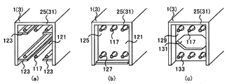
図12の(a)図は、図2のAに示す部分の垂直方向の断面図を、図12の(b)図および図12の(c)図は、接続部19jの垂直断面図を示す。図12の(b)図は、図12の(a)図のM1−M1による断面図、図12の(b)図は、図12の(a)図のM2−M2(M3−M3)による断面図である。図12の(d)図は、コンクリート109を設置する前のセグメント25(セグメント31)の端部付近の斜視図を示す。   12A is a vertical sectional view of the portion shown in FIG. 2A, and FIG. 12B and FIG. 12C are vertical sectional views of the connecting portion 19j. . 12B is a cross-sectional view taken along line M1-M1 in FIG. 12A, and FIG. 12B is taken along line M2-M2 (M3-M3) in FIG. It is sectional drawing. FIG. 12D shows a perspective view of the vicinity of the end of the segment 25 (segment 31) before the concrete 109 is installed.

図12に示すように、接続部19jは、セグメント25(セグメント31)の内側面に固定された鋼板115、一端がセグメント25内に、他端がセグメント31内に配置された鉄筋117、鉄筋117の周囲に設置されたコンクリート109等からなる。   As shown in FIG. 12, the connecting portion 19 j includes a steel plate 115 fixed to the inner surface of the segment 25 (segment 31), a reinforcing bar 117, one end disposed in the segment 25, and the other end disposed in the segment 31, a reinforcing bar 117. It consists of concrete 109 etc. installed around the.

鋼板115は、セグメント25、セグメント31の縦リブに、切欠き部121と穴119とを加工したものである。鉄筋117は、一端が、セグメント25に固定された鋼板115の穴119に挿入され、他端が、セグメント31に固定された鋼板115の穴119に挿入される。コンクリート109は、鉄筋117の周囲に打設される。接続部19jでは、鋼板115に切欠き部121を設けることにより、セグメント25およびセグメント31の内部へのコンクリート109の充填性が高まる。   The steel plate 115 is obtained by processing notches 121 and holes 119 in the vertical ribs of the segments 25 and 31. One end of the reinforcing bar 117 is inserted into the hole 119 of the steel plate 115 fixed to the segment 25, and the other end is inserted into the hole 119 of the steel plate 115 fixed to the segment 31. The concrete 109 is placed around the reinforcing bar 117. In the connection part 19j, the notch part 121 is provided in the steel plate 115, whereby the filling properties of the concrete 109 into the segments 25 and 31 are enhanced.

図12に示すような接続部19jを形成するには、セグメント25とセグメント31との間に鉄筋117を設置する工程と、コンクリート109を打設する工程を、トンネル軸方向に順次繰り返す。   In order to form the connecting portion 19j as shown in FIG. 12, the step of installing the reinforcing bar 117 between the segment 25 and the segment 31 and the step of placing the concrete 109 are sequentially repeated in the tunnel axis direction.

接続部19jを形成する際には、本線トンネル1とランプトンネル3との間隔の変化に伴う接続部19jの長さの変化には、鉄筋117の長さを変化させて対応する。   When forming the connecting portion 19j, the length of the reinforcing bar 117 is changed in response to the change in the length of the connecting portion 19j accompanying the change in the distance between the main tunnel 1 and the lamp tunnel 3.

第6の実施の形態では、図1に示す接続部19bも、接続部19jと同様の部材および方法で構成される。   In the sixth embodiment, the connecting portion 19b shown in FIG. 1 is also configured by the same members and methods as the connecting portion 19j.

第6の実施の形態においても、図1に示すような工程で本線トンネル1とランプトンネル3を接続することにより、合成トンネル23の形成時に、トンネルの躯体の撤去範囲や地盤改良の範囲、トンネル用地幅を縮小できる。また、図12に示すように、接続部19jを形成する際に、セグメント25およびセグメント31の縦リブに穴119や切欠き部121を加工した鋼板115を用いることにより、鉄筋117を多く配置できる。また、従来のカプラ式継手やラップ式継手等と比較して、鉄筋117からセグメント25やセグメント31に効率よく力を伝達できる。   Also in the sixth embodiment, the main tunnel 1 and the lamp tunnel 3 are connected in the process as shown in FIG. 1, so that when the synthetic tunnel 23 is formed, the tunnel housing removal range, ground improvement range, tunnel The site width can be reduced. In addition, as shown in FIG. 12, when the connecting portion 19j is formed, a large number of reinforcing bars 117 can be arranged by using the steel plate 115 in which the holes 119 and the notches 121 are processed in the vertical ribs of the segment 25 and the segment 31. . In addition, compared with conventional coupler-type joints, lap-type joints, and the like, force can be efficiently transmitted from the reinforcing bars 117 to the segments 25 and 31.

なお、セグメント25やセグメント31に固定される鋼板の形状は、図12に示すものに限らない。図13は、他の形状の鋼板が固定されたセグメント25(セグメント31)の端部付近の斜視図を示す。   In addition, the shape of the steel plate fixed to the segment 25 or the segment 31 is not limited to that shown in FIG. FIG. 13 is a perspective view of the vicinity of the end of the segment 25 (segment 31) to which a steel plate having another shape is fixed.

図13の(a)図に示すセグメント25(セグメント31)では、セグメント25(セグメント31)の内側面に、セグメント25(セグメント31)のスキンプレートに平行な鋼板123が固定される。鉄筋117の端部は、セグメント25(セグメント31)内において、鋼板123に平行に配置される。   In the segment 25 (segment 31) shown in FIG. 13A, a steel plate 123 parallel to the skin plate of the segment 25 (segment 31) is fixed to the inner surface of the segment 25 (segment 31). The ends of the reinforcing bars 117 are arranged in parallel to the steel plate 123 in the segment 25 (segment 31).

図13の(b)図に示すセグメント25(セグメント31)の内側面に固定された鋼板125は、セグメント25(セグメント31)の縦リブを、下端部を曲げてL字型に成形したものである。鋼板125は、複数の穴127を有する。鉄筋117の端部は、セグメント25(セグメント31)内において、鋼板125の穴127に挿入される。   The steel plate 125 fixed to the inner surface of the segment 25 (segment 31) shown in FIG. 13 (b) is formed by bending the bottom rib of the segment 25 (segment 31) into an L-shape. is there. The steel plate 125 has a plurality of holes 127. The end of the reinforcing bar 117 is inserted into the hole 127 of the steel plate 125 in the segment 25 (segment 31).

図13の(c)図に示すセグメント25(セグメント31)の内側面に固定された鋼板129は、セグメント25(セグメント31)の縦リブに切欠き部141と穴133とを設けたものである。鉄筋117の端部は、セグメント25(セグメント31)内において、鋼板129の穴131に挿入される。   A steel plate 129 fixed to the inner side surface of the segment 25 (segment 31) shown in FIG. 13C is obtained by providing a notch 141 and a hole 133 in the vertical rib of the segment 25 (segment 31). . The end of the reinforcing bar 117 is inserted into the hole 131 of the steel plate 129 in the segment 25 (segment 31).

図13に示すような鋼板を用いた場合にも、鉄筋117を多く配置できる。また、従来のカプラ式継手やラップ式継手等と比較して、鉄筋117からセグメント25やセグメント31に効率よく力を伝達できる。   Even when a steel plate as shown in FIG. 13 is used, many reinforcing bars 117 can be arranged. In addition, compared with conventional coupler-type joints, lap-type joints, and the like, force can be efficiently transmitted from the reinforcing bars 117 to the segments 25 and 31.

次に、第7の実施の形態について説明する。図14は、本線トンネル1とランプトンネル3を接続して合成トンネル23aを形成するための各工程を示す図である。図14に示すように、本線トンネル1は、地盤11内に設置され、周方向の断面がほぼD字型である。ランプトンネル3は、地盤11内に設置され、周方向の断面が円形である。合成トンネル23aの形成部分において、本線トンネル1とランプトンネル3との間隔は、徐々に変化する。   Next, a seventh embodiment will be described. FIG. 14 is a diagram showing steps for connecting the main tunnel 1 and the lamp tunnel 3 to form the composite tunnel 23a. As shown in FIG. 14, the main tunnel 1 is installed in the ground 11 and has a substantially D-shaped circumferential section. The lamp tunnel 3 is installed in the ground 11 and has a circular cross section in the circumferential direction. In the formation portion of the composite tunnel 23a, the interval between the main tunnel 1 and the lamp tunnel 3 gradually changes.

第7の実施の形態では、本線トンネル1とランプトンネル3とを接合する方法について説明する。図14の(a)図は、地盤11の掘削部17d、掘削部17eを掘削して支保工を設置する工程を示す。図14の(a)図では、まず、本線トンネル1およびランプトンネル3の上方・下方の地盤11に、凍結工法等を用いて地盤改良9を行う。   In the seventh embodiment, a method of joining the main tunnel 1 and the lamp tunnel 3 will be described. FIG. 14A shows a process of excavating the excavation part 17d and excavation part 17e of the ground 11 and installing a support work. In FIG. 14A, first, ground improvement 9 is performed on the ground 11 above and below the main tunnel 1 and the ramp tunnel 3 using a freezing method or the like.

そして、本線トンネル1の上半部のセグメント14cのスキンプレート、ランプトンネル3の上半部のセグメント14dのスキンプレートを撤去し、本線トンネル1とランプトンネル3の間の掘削部17dを掘削して、本線トンネル1とランプトンネル3との間に、掘削部17dを通る水平方向支保工7cを設置する。   Then, the skin plate of the segment 14c in the upper half of the main tunnel 1 and the skin plate of the segment 14d in the upper half of the ramp tunnel 3 are removed, and the excavation portion 17d between the main tunnel 1 and the ramp tunnel 3 is excavated. A horizontal support 7c passing through the excavation part 17d is installed between the main tunnel 1 and the ramp tunnel 3.

また、本線トンネル1の下半部のセグメント14eのスキンプレート、ランプトンネル3の下半部のセグメント14fのスキンプレートを撤去し、本線トンネル1とランプトンネル3の間の掘削部17eを掘削して、本線トンネル1とランプトンネル3との間に、掘削部17eを通る水平方向支保工7cを設置する。   Further, the skin plate of the segment 14e in the lower half of the main tunnel 1 and the skin plate of the segment 14f in the lower half of the ramp tunnel 3 are removed, and an excavation 17e between the main tunnel 1 and the ramp tunnel 3 is excavated. A horizontal support 7c passing through the excavation part 17e is installed between the main line tunnel 1 and the ramp tunnel 3.

図14の(b)図は、掘削部17fを掘削する工程を示す。図14の(b)図では、図14の(a)図で掘削した掘削部17d、掘削部17eを埋め戻す。そして、本線トンネル1の上半部のセグメント13eのスキンプレートとランプトンネル3の上半部のセグメント13fのスキンプレートを撤去し、本線トンネル1とランプトンネル3の間の掘削部17fを掘削する。   FIG. 14B shows a process of excavating the excavation part 17f. In FIG. 14B, the excavation part 17d and excavation part 17e excavated in FIG. 14A are backfilled. Then, the skin plate of the segment 13e in the upper half of the main tunnel 1 and the skin plate of the segment 13f in the upper half of the ramp tunnel 3 are removed, and the excavation part 17f between the main tunnel 1 and the ramp tunnel 3 is excavated.

図14の(c)図は、接続部19cを設置する工程を示す。図14の(c)図では、図14の(b)図でスキンプレートを撤去した本線トンネル1の上半部のセグメント13eの主桁の間、ランプトンネル3の上半部のセグメント13fの主桁の間を通して、本線トンネル1とランプトンネル3の上半部同士を連結する接続部19kを設置する。接続部19kの詳細な構造については後述する。接続部19kを設置した後、接続部19kの外周側に位置する掘削部17fの埋め戻し21を行う。埋め戻し21は、現地発生土やモルタル等の埋め戻し材を用いて行う。   FIG. 14C shows a process of installing the connecting portion 19c. 14 (c), the main girder of the upper half segment 13e of the main tunnel 1 from which the skin plate has been removed in FIG. A connecting portion 19k that connects the upper half portions of the main tunnel 1 and the lamp tunnel 3 through the girder is installed. The detailed structure of the connecting portion 19k will be described later. After the connection portion 19k is installed, backfilling 21 of the excavation portion 17f located on the outer peripheral side of the connection portion 19k is performed. The backfill 21 is performed using a backfill material such as locally generated soil or mortar.

なお、図14の(a)図に示す工程で地盤改良9に凍結工法を用いた場合には、埋め戻し21を行った後の適切な時期に、本線トンネル1およびランプトンネル3の上方の地盤11の凍結を解除する。   In addition, when the freezing method is used for the ground improvement 9 in the step shown in FIG. 14A, the ground above the main tunnel 1 and the ramp tunnel 3 at an appropriate time after the backfill 21 is performed. 11 freezing is released.

図14の(d)図は、掘削部17d、掘削部17e、掘削部17f、掘削部g、掘削部17h、掘削部17iを掘削する工程を示す図である。図14の(d)図では、本線トンネル1の上半部のセグメント14gのスキンプレートとランプトンネル3の上半部のセグメント14hのスキンプレートを撤去し、本線トンネル1とランプトンネル3の間の掘削部17gを掘削する。また、掘削部17dを再度掘削する。   FIG. 14D is a diagram illustrating a process of excavating the excavation unit 17d, the excavation unit 17e, the excavation unit 17f, the excavation unit g, the excavation unit 17h, and the excavation unit 17i. 14D, the skin plate of the upper half segment 14g of the main tunnel 1 and the skin plate 14h of the upper half segment 14h of the lamp tunnel 3 are removed, and the space between the main tunnel 1 and the lamp tunnel 3 is removed. Excavation part 17g is excavated. Moreover, the excavation part 17d is excavated again.

また、本線トンネル1の中央部のセグメント14iのスキンプレートとランプトンネル3の中央部のセグメント14jのスキンプレートを撤去し、本線トンネル1とランプトンネル3の間の掘削部17hを掘削する。また、掘削部17eを再度掘削する。   Further, the skin plate of the segment 14 i in the center portion of the main tunnel 1 and the skin plate of the segment 14 j in the center portion of the ramp tunnel 3 are removed, and the excavation portion 17 h between the main tunnel 1 and the ramp tunnel 3 is excavated. Moreover, the excavation part 17e is excavated again.

さらに、本線トンネル1の下半部のセグメント13gのスキンプレートとランプトンネル3の下半部のセグメント13hのスキンプレートを撤去し、本線トンネル1とランプトンネル3の間の掘削部17iを掘削する。   Further, the skin plate of the segment 13 g in the lower half of the main tunnel 1 and the skin plate of the segment 13 h in the lower half of the ramp tunnel 3 are removed, and an excavation part 17 i between the main tunnel 1 and the ramp tunnel 3 is excavated.

図14の(e)図は、接続部19dを設置して合成トンネル23aを完成する工程を示す。図14の(e)図では、図14の(d)図でスキンプレートを撤去した本線トンネル1の下半部のセグメント13gの主桁の間、ランプトンネル3の下半部のセグメント13hの主桁の間を通して、本線トンネル1とランプトンネル3の下半部同士を連結する接続部19lを設置する。   FIG. 14E shows a process of installing the connecting portion 19d and completing the synthetic tunnel 23a. In FIG. 14 (e), the main girder of the lower half segment 13g of the main tunnel 1 from which the skin plate is removed in FIG. A connecting portion 19l that connects the lower half portions of the main tunnel 1 and the lamp tunnel 3 through the girder is installed.

図14の(e)図では、接続部19lを設置した後、接続部19lの外周側に位置する掘削部17iの埋め戻し(図示せず)を行う。そして、本線トンネル1のセグメント14c、セグメント14e、セグメント14g、セグメント14iの残りの部分、ランプトンネル3のセグメント14d、セグメント14f、セグメント14h、セグメント14jの残りの部分、水平方向支保工7c、水平方向支保工7cを撤去し、合成トンネル23aを完成する。   In FIG. 14 (e), after the connection portion 19l is installed, the excavation portion 17i located on the outer peripheral side of the connection portion 19l is backfilled (not shown). Then, the segment 14c, segment 14e, segment 14g, remaining portion of the segment 14i of the main tunnel 1, the segment 14d, segment 14f, segment 14h, the remaining portion of the segment 14j of the ramp tunnel 3, the horizontal support 7c, the horizontal direction The support work 7c is removed, and the synthetic tunnel 23a is completed.

なお、図14の(a)図に示す工程で地盤改良9に凍結工法を用いた場合には、埋め戻し(図示せず)を行った後、本線トンネル1およびランプトンネル3の下方の地盤11の凍結を解除する。   In addition, when the freezing method is used for the ground improvement 9 in the process shown in FIG. 14A, after the backfilling (not shown), the ground 11 below the main tunnel 1 and the ramp tunnel 3 is used. Unfreeze.

以下に、接続部19kの詳細な構造について述べる。図15は、接続部19k付近の斜視図を、図16は、接続部19k付近の断面図を示す。図15は、図2のAに示す部分の斜視図である。図15、図16に示すように、接続部19kは、本線トンネル1のセグメント25の主桁の間と、ランプトンネル3のセグメント31の主桁の間とを通して設置される。   Below, the detailed structure of the connection part 19k is described. 15 is a perspective view of the vicinity of the connection portion 19k, and FIG. 16 is a cross-sectional view of the vicinity of the connection portion 19k. FIG. 15 is a perspective view of the portion shown in FIG. As shown in FIGS. 15 and 16, the connecting portion 19 k is installed between the main beam of the segment 25 of the main tunnel 1 and between the main beam of the segment 31 of the ramp tunnel 3.

図16の(a)図は、図5に示す部分の水平方向の断面図を、図16の(b)図は、図5に示す部分の垂直方向の断面図を示す。図16の(a)図は、図16の(b)図のH2−H2による断面図、図16の(b)図は、図16の(a)図のH1−H1による断面図である。   16A is a horizontal sectional view of the portion shown in FIG. 5, and FIG. 16B is a vertical sectional view of the portion shown in FIG. 16A is a cross-sectional view taken along line H2-H2 in FIG. 16B, and FIG. 16B is a cross-sectional view taken along line H1-H1 in FIG.

図15、図16の(a)図、図16の(b)図に示すように、接続部19kは、セグメント25の内周面に固定された取り付け用治具93、一端が取り付け用治具93に固定されたコマ材27、一端がコマ材27の他端に固定され、他端が取り付け用治具93に固定されたH型鋼29、セグメント31の内周面に固定された取り付け用治具93、隣り合う2本のH型鋼29の間の空間を補強する軸方向補強材39等からなる。   As shown in FIGS. 15 and 16 (a) and 16 (b), the connecting portion 19k has an attachment jig 93 fixed to the inner peripheral surface of the segment 25, and one end of the attachment jig 93. The frame member 27 fixed to 93, one end fixed to the other end of the frame member 27, the other end fixed to the mounting jig 93, and the mounting jig fixed to the inner peripheral surface of the segment 31. The tool 93, the axial reinforcing material 39 that reinforces the space between two adjacent H-shaped steels 29, and the like.

図16に示すように、取り付け用治具93は、セグメント25やセグメント31の端面97に平行な継手板95、継手板95に垂直な補強板98等からなる。取り付け用治具93の補強板98は、セグメント25およびセグメント31の内周面に溶接等により固定される。取り付け用治具93の補強板98の溶接は、現場や工場で行われる。このとき、継手板95は、セグメント25やセグメント31の端面97の下方に配置される。   As shown in FIG. 16, the attachment jig 93 includes a joint plate 95 parallel to the end surfaces 97 of the segments 25 and 31, a reinforcing plate 98 perpendicular to the joint plate 95, and the like. The reinforcing plate 98 of the mounting jig 93 is fixed to the inner peripheral surfaces of the segment 25 and the segment 31 by welding or the like. Welding of the reinforcing plate 98 of the mounting jig 93 is performed at the site or factory. At this time, the joint plate 95 is disposed below the end surfaces 97 of the segment 25 and the segment 31.

コマ材27、H型鋼29、軸方向補強材39には、第1の実施の形態で用いたもの(図4の(a)図、図4の(b)図)と同様のものを用いる。コマ材27の継手板33と取り付け用治具93の継手板95、コマ材27の継手板33とH型鋼29の継手板35、H型鋼29の継手板35と取り付け用治具93の継手板95は、それぞれ、短ボルトおよびナット37によって固定される。軸方向補強材39の一端は、H型鋼29の上下のフランジの間に挿入される。軸方向補強材39の他端は、隣り合う他のH型鋼29の上下のフランジの間に挿入される。   As the top member 27, the H-shaped steel 29, and the axial direction reinforcing member 39, the same materials as those used in the first embodiment (FIG. 4 (a) and FIG. 4 (b)) are used. The joint plate 33 of the top member 27 and the joint plate 95 of the mounting jig 93, the joint plate 33 of the top member 27 and the joint plate 35 of the H-shaped steel 29, the joint plate 35 of the H-shaped steel 29 and the joint plate of the mounting jig 93 95 is fixed by a short bolt and a nut 37, respectively. One end of the axial reinforcing member 39 is inserted between the upper and lower flanges of the H-shaped steel 29. The other end of the axial reinforcing member 39 is inserted between the upper and lower flanges of another adjacent H-shaped steel 29.

接続部19の長さは、図2に示すように、本線トンネル1とランプトンネル3の設置間隔によって変化する。図2のBに示す部分において、接続部19kの構成は、図2のAに示す部分(図16)とほぼ同様である。図2のBに示す部分の接続部19kでは、図2のAに示す部分の接続部19kのコマ材27の替わりに、コマ材27aと誤差吸収プレート41とが用いられる。   As shown in FIG. 2, the length of the connecting portion 19 varies depending on the installation interval between the main tunnel 1 and the lamp tunnel 3. In the portion shown in FIG. 2B, the configuration of the connecting portion 19k is substantially the same as the portion shown in FIG. 2A (FIG. 16). In the connection portion 19k shown in FIG. 2B, the piece material 27a and the error absorbing plate 41 are used instead of the piece material 27 of the connection portion 19k shown in FIG.

すなわち、図2のBに示す部分の接続部19kは、図4の(c)図、図4の(d)図に示す接続部19aのコマ材27aの端部、H型鋼29の端部が取り付け用治具93の継手板95に固定され、取り付け用治具93の補強板98がセグメント25、セグメント31の内周面に溶接等によって固定されたものである。   That is, the connection part 19k of the part shown in B of FIG. 2 has the end part of the piece 27a of the connection part 19a shown in FIG. 4 (c) and FIG. 4 (d), and the end part of the H-shaped steel 29. It is fixed to the joint plate 95 of the mounting jig 93, and the reinforcing plate 98 of the mounting jig 93 is fixed to the inner peripheral surfaces of the segments 25 and 31 by welding or the like.

接続部19kを形成する際には、コマ材27、コマ材27aの大きさを一定とし、本線トンネル1とランプトンネル3との間隔の変化に伴う接続部19kの長さの変化には、H型鋼29の長さを変化させて対応する。コマ材27aを用いる部分では、数種類の厚さの誤差吸収プレート41を準備しておき、適切な厚さの誤差吸収プレート41を用いることにより施工誤差を吸収する。   When forming the connecting portion 19k, the sizes of the top material 27 and the top material 27a are fixed, and the change in the length of the connecting portion 19k due to the change in the distance between the main tunnel 1 and the lamp tunnel 3 includes H The length of the steel plate 29 is changed to cope with it. In the portion using the top material 27a, several types of error absorbing plates 41 having different thicknesses are prepared, and the construction error is absorbed by using the error absorbing plate 41 having an appropriate thickness.

第7の実施の形態では、図14に示す接続部19lも、接続部19kと同様の部材および方法で構成される。   In the seventh embodiment, the connecting portion 19l shown in FIG. 14 is also configured by the same members and methods as the connecting portion 19k.

このように、第7の実施の形態では、図14に示すような工程で本線トンネル1とランプトンネル3を接続することにより、合成トンネル23aの形成時に、トンネルの躯体の撤去範囲や地盤改良の範囲、トンネル用地幅を縮小できる。また、図16に示すように、接続部19kを形成する際に、自重や曲げ剛性が比較的小さいH型鋼29等の鋼材を用いることにより、RC構造と比べて断面力を小さく抑えることが可能となる。図16に示す接続部19kでは、コマ材27や、コマ材27aと誤差吸収プレート41を用いた単純な構造で、ある程度の施工誤差に対処できる。   As described above, in the seventh embodiment, the main tunnel 1 and the ramp tunnel 3 are connected in a process as shown in FIG. 14, so that when the synthetic tunnel 23 a is formed, the removal range of the tunnel frame and the ground improvement are improved. Range, tunnel width can be reduced. Also, as shown in FIG. 16, when forming the connecting portion 19k, the cross-sectional force can be suppressed smaller than that of the RC structure by using a steel material such as H-shaped steel 29 having a relatively low weight and bending rigidity. It becomes. In the connecting portion 19k shown in FIG. 16, a simple construction using the top material 27, the top material 27a and the error absorbing plate 41 can cope with a certain degree of construction error.

なお、第7の実施の形態では、接続部19を図16に示す接続部19kのような構造としたが、接続部19の構造は、これに限らない。   In the seventh embodiment, the connecting portion 19 has a structure like the connecting portion 19k shown in FIG. 16, but the structure of the connecting portion 19 is not limited to this.

図17は、他の構造の接続部19m付近の断面図である。図17の(a)図は、図15に示す部分の水平方向の断面図を、図17の(b)図は、図15に示す部分の垂直方向の断面図を示す。図17の(a)図は、図17の(b)図のI2−I2による断面図、図17の(b)図は、図17の(a)図のI1−I1による断面図である。   FIG. 17 is a cross-sectional view of the vicinity of the connecting portion 19m having another structure. 17A is a horizontal sectional view of the portion shown in FIG. 15, and FIG. 17B is a vertical sectional view of the portion shown in FIG. 17A is a cross-sectional view taken along the line I2-I2 in FIG. 17B, and FIG. 17B is a cross-sectional view taken along the line I1-I1 in FIG.

図17の(a)図、図17の(b)図に示すように、接続部19mは、セグメント25の内周面に固定された取り付け用治具93a、一端が取り付け用治具93aに固定されたコマ材27、一端がコマ材27の他端に固定され、他端が取り付け用治具93aに固定されたH型鋼29、セグメント31の内周面に固定された取り付け用治具93a、隣り合う2本のH型鋼29の間の空間を補強する軸方向補強材39等からなる。   As shown in FIGS. 17A and 17B, the connecting portion 19m has an attachment jig 93a fixed to the inner peripheral surface of the segment 25, and one end fixed to the attachment jig 93a. The frame piece 27, one end fixed to the other end of the piece member 27, the other end fixed to the attachment jig 93a, the H-shaped steel 29, the attachment jig 93a fixed to the inner peripheral surface of the segment 31, It consists of the axial direction reinforcement material 39 etc. which reinforce the space between two adjacent H-shaped steel 29. FIG.

図17に示すように、取り付け用治具93aは、セグメント25やセグメント31の端面を延長した継手板97a、継手板97aに垂直な補強板98等からなる。取り付け用治具93の補強板98は、セグメント25およびセグメント31の内周面に固定される。   As shown in FIG. 17, the attachment jig 93a includes a joint plate 97a obtained by extending end surfaces of the segment 25 and the segment 31, a reinforcing plate 98 perpendicular to the joint plate 97a, and the like. The reinforcing plate 98 of the mounting jig 93 is fixed to the inner peripheral surfaces of the segment 25 and the segment 31.

コマ材27、H型鋼29、軸方向補強材39には、第7の実施の形態で用いたもの(図16)と同様のものを用いる。コマ材27の継手板33と取り付け用治具93の継手板97a、コマ材27の継手板33とH型鋼29の継手板35、H型鋼29の継手板35と取り付け用治具93の継手板97aは、それぞれ、短ボルトおよびナット37によって固定される。軸方向補強材39の一端は、H型鋼29の上下のフランジの間に挿入される。軸方向補強材39の他端は、隣り合う他のH型鋼29の上下のフランジの間に挿入される。   As the top material 27, the H-shaped steel 29, and the axial direction reinforcing material 39, the same materials as those used in the seventh embodiment (FIG. 16) are used. The joint plate 33 of the top member 27 and the joint plate 97a of the mounting jig 93, the joint plate 33 of the top member 27 and the joint plate 35 of the H-shaped steel 29, the joint plate 35 of the H-shaped steel 29 and the joint plate of the mounting jig 93 97a is fixed by a short bolt and a nut 37, respectively. One end of the axial reinforcing member 39 is inserted between the upper and lower flanges of the H-shaped steel 29. The other end of the axial reinforcing member 39 is inserted between the upper and lower flanges of another adjacent H-shaped steel 29.

第7の実施の形態では、接続部19として、図5から図12に示すような他の接続部と図16に示す接続部19kの取り付け用治具93や図17に示す接続部19mの取り付け用治具93aとを組み合わせたものを用いてもよい。   In the seventh embodiment, the connecting portion 19 is attached to another connecting portion as shown in FIGS. 5 to 12 and the attachment jig 93 for the connecting portion 19k shown in FIG. 16 or the connecting portion 19m shown in FIG. A combination of the jig 93a for use may be used.

次に、第8の実施の形態について説明する。図18は、本線トンネル1とランプトンネル3を接続して合成トンネル23bを形成するための各工程を示す図である。図18に示すように、本線トンネル1は、地盤11内に設置され、周方向の断面がほぼD字型である。ランプトンネル3は、地盤11内に設置され、周方向の断面が円形である。合成トンネル23bの形成部分において、本線トンネル1とランプトンネル3との間隔は、徐々に変化する。   Next, an eighth embodiment will be described. FIG. 18 is a diagram showing steps for connecting the main tunnel 1 and the lamp tunnel 3 to form the composite tunnel 23b. As shown in FIG. 18, the main tunnel 1 is installed in the ground 11 and has a substantially D-shaped circumferential cross section. The lamp tunnel 3 is installed in the ground 11 and has a circular cross section in the circumferential direction. In the formation portion of the composite tunnel 23b, the distance between the main tunnel 1 and the lamp tunnel 3 gradually changes.

第8の実施の形態では、本線トンネル1とランプトンネル3とを接合する方法について説明する。図18の(a)図は、地盤11の掘削部17j、掘削部17kを掘削して上弦材105aを設置する工程を示す。図18の(a)図では、まず、本線トンネル1およびランプトンネル3の上方・下方の地盤11に、凍結工法等を用いて地盤改良9を行う。   In the eighth embodiment, a method of joining the main tunnel 1 and the lamp tunnel 3 will be described. FIG. 18A shows a process of excavating the excavation part 17j and excavation part 17k of the ground 11 and installing the upper chord material 105a. In FIG. 18A, first, ground improvement 9 is performed on the ground 11 above and below the main tunnel 1 and the ramp tunnel 3 using a freezing method or the like.

そして、本線トンネル1の上半部のセグメント14kのスキンプレート、ランプトンネル3の上半部のセグメント14lのスキンプレートを撤去し、本線トンネル1とランプトンネル3の間の掘削部17jを掘削して、本線トンネル1とランプトンネル3との間に、掘削部17jを通る下弦材109aを設置する。   Then, the skin plate of the segment 14k in the upper half of the main tunnel 1 and the skin plate of the segment 14l in the upper half of the ramp tunnel 3 are removed, and an excavation portion 17j between the main tunnel 1 and the ramp tunnel 3 is excavated. The lower chord material 109a passing through the excavation part 17j is installed between the main tunnel 1 and the ramp tunnel 3.

また、本線トンネル1の上半部のセグメント13iのスキンプレート、ランプトンネル3の上半部のセグメント13jのスキンプレートを撤去し、本線トンネル1とランプトンネル3の間の掘削部17kを掘削する。次に、セグメント13i、セグメント13jの残りの部分を撤去して、本線トンネル1とランプトンネル3の上半部同士を連結する上弦材105aを設置する。上弦材105aは、第1の実施の形態の接続部19aに相当するものであり、図4に示す接続部19aと同様の構成とする。   Further, the skin plate of the segment 13 i in the upper half of the main tunnel 1 and the skin plate of the segment 13 j in the upper half of the ramp tunnel 3 are removed, and the excavation part 17 k between the main tunnel 1 and the ramp tunnel 3 is excavated. Next, the remaining portions of the segments 13i and 13j are removed, and the upper chord material 105a that connects the upper half portions of the main tunnel 1 and the lamp tunnel 3 is installed. The upper chord material 105a corresponds to the connecting portion 19a of the first embodiment, and has the same configuration as the connecting portion 19a shown in FIG.

図18の(b)図では、トラス材107aを設置し、掘削部17l、掘削部17m、掘削部17nを掘削する工程を示す。図18の(b)図では、図18の(a)図で掘削した掘削部17j、掘削部17kにトラス材107aを設置する。トラス材107aは、上弦材105aの内周側に沿って、上弦材105aと下弦材109aとの間に配置される。次に、上弦材105aの外周側に位置する掘削部17kの埋め戻し21を行う。埋め戻し21は、現地発生土やモルタル等の埋め戻し材を用いて行う。   FIG. 18B shows a process of installing the truss member 107a and excavating the excavation part 17l, the excavation part 17m, and the excavation part 17n. In FIG. 18 (b), truss members 107a are installed in the excavation part 17j and excavation part 17k excavated in FIG. 18 (a). The truss member 107a is disposed between the upper chord member 105a and the lower chord member 109a along the inner peripheral side of the upper chord member 105a. Next, the backfill 21 of the excavation part 17k located on the outer peripheral side of the upper chord material 105a is performed. The backfill 21 is performed using a backfill material such as locally generated soil or mortar.

なお、図18の(a)図に示す工程で地盤改良9に凍結工法を用いた場合には、埋め戻し21を行った後の適切な時期に、本線トンネル1およびランプトンネル3の上方の地盤11の凍結を解除する。   When the freezing method is used for the ground improvement 9 in the step shown in FIG. 18A, the ground above the main tunnel 1 and the ramp tunnel 3 at an appropriate time after the backfill 21 is performed. 11 freezing is released.

図18の(b)図では、埋め戻し21を行った後、本線トンネル1の中央部のセグメント14mのスキンプレート、ランプトンネル3の中央部のセグメント14nのスキンプレートを撤去し、本線トンネル1とランプトンネル3との間の掘削部17lを掘削して、本線トンネル1とランプトンネル3との間に掘削部17lを通る水平方向支保工7dを設置する。   In FIG. 18B, after the backfill 21 is performed, the skin plate of the segment 14m at the center of the main tunnel 1 and the skin plate of the segment 14n at the center of the ramp tunnel 3 are removed, and the main tunnel 1 and The excavation part 17 l between the ramp tunnel 3 is excavated, and a horizontal support 7 d passing through the excavation part 17 l is installed between the main tunnel 1 and the ramp tunnel 3.

また、本線トンネル1の下半部のセグメント14oのスキンプレート、ランプトンネル3の下半部のセグメント14pのスキンプレートを撤去し、本線トンネル1とランプトンネル3との間の掘削部17mを掘削して、本線トンネル1とランプトンネル3との間に掘削部17lを通る下弦材109bを設置する。   In addition, the skin plate of the segment 14o in the lower half of the main tunnel 1 and the skin plate of the segment 14p in the lower half of the ramp tunnel 3 are removed, and the excavation portion 17m between the main tunnel 1 and the ramp tunnel 3 is excavated. Thus, the lower chord material 109b passing through the excavation part 17l is installed between the main tunnel 1 and the ramp tunnel 3.

さらに、本線トンネル1の下半部のセグメント13kのスキンプレート、ランプトンネル3の下半部のセグメント13lのスキンプレートを撤去し、本線トンネル1とランプトンネル3との間の掘削部17nを掘削する。   Further, the skin plate of the segment 13k in the lower half of the main tunnel 1 and the skin plate of the segment 13l in the lower half of the ramp tunnel 3 are removed, and an excavation portion 17n between the main tunnel 1 and the ramp tunnel 3 is excavated. .

図18の(c)図は、上弦材105b、トラス材107bを設置する工程を示す図である。図18の(c)図では、本線トンネル1の下半部のセグメント13kの残りの部分、ランプトンネル3の下半部のセグメント13lの残りの部分を撤去し、本線トンネル1とランプトンネル3の下半部同士を連結する上弦材105bを設置する。上弦材105bは、第1の実施の形態の接続部19bに相当するものである。   FIG. 18C is a diagram illustrating a process of installing the upper chord member 105b and the truss member 107b. In FIG. 18C, the remaining portion of the lower half segment 13k of the main tunnel 1 and the remaining portion 13l of the lower half segment 13l of the ramp tunnel 3 are removed, and the main tunnel 1 and the ramp tunnel 3 are removed. An upper chord material 105b that connects the lower halves is installed. The upper chord material 105b corresponds to the connecting portion 19b of the first embodiment.

図18の(c)図では、上弦材105bを設置した後、上弦材105bの外周側に位置する掘削部17nの埋め戻し21を行う。そして、図18の(b)図で掘削した掘削部17m、掘削部17nにトラス材107bを設置する。トラス材107bは、上弦材105bの内周側に沿って、上弦材105bと下弦材109bとの間に配置される。   In FIG. 18 (c), after the upper chord member 105b is installed, the backfill 21 of the excavation part 17n located on the outer peripheral side of the upper chord member 105b is performed. And truss material 107b is installed in the excavation part 17m and excavation part 17n which were excavated in FIG.18 (b) figure. The truss member 107b is disposed between the upper chord member 105b and the lower chord member 109b along the inner peripheral side of the upper chord member 105b.

なお、図18の(a)図に示す工程で地盤改良9に凍結工法を用いた場合には、埋め戻し21を行った後、本線トンネル1およびランプトンネル3の下方の地盤11の凍結を解除する。   When the freezing method is used for the ground improvement 9 in the process shown in FIG. 18A, after the backfill 21 is performed, the freezing of the ground 11 below the main tunnel 1 and the ramp tunnel 3 is released. To do.

図18の(d)図は、水平方向支保工7d等を撤去して合成トンネル23aを完成する工程を示す。図18の(d)図では、本線トンネル1のセグメント14m、セグメント14oの残りの部分、ランプトンネル3のセグメント14n、セグメント14pの残りの部分、水平方向支保工7dを撤去し、合成トンネル23bを完成する。   FIG. 18D shows a process of removing the horizontal support 7d and the like to complete the synthetic tunnel 23a. In FIG. 18 (d), the segment 14m of the main tunnel 1, the remaining portion of the segment 14o, the segment 14n of the ramp tunnel 3, the remaining portion of the segment 14p, and the horizontal support 7d are removed, and the synthetic tunnel 23b is removed. Complete.

このように、第8の実施の形態では、図18に示すような工程で本線トンネル1とランプトンネル3を接続することにより、合成トンネル23bの形成時に、トンネルの躯体の撤去範囲や地盤改良の範囲、トンネル用地幅を縮小できる。   As described above, in the eighth embodiment, the main tunnel 1 and the ramp tunnel 3 are connected in a process as shown in FIG. 18, so that when the synthetic tunnel 23 b is formed, the removal range of the tunnel body and the ground improvement are improved. Range, tunnel width can be reduced.

なお、第8の実施の形態では、上弦材105a、上弦材105bを図4に示す接続部19aのような構造としたが、上弦材105a、上弦材105bの構造は、これに限らない。上弦材105a、上弦材105bは、図5から図12に示すような他の接続部と同様の構造としてもよい。   In the eighth embodiment, the upper chord material 105a and the upper chord material 105b have a structure like the connecting portion 19a shown in FIG. 4, but the structures of the upper chord material 105a and the upper chord material 105b are not limited thereto. The upper chord material 105a and the upper chord material 105b may have the same structure as other connecting portions as shown in FIGS.

第1、第7、第8の実施の形態では、本線トンネル1とランプトンネル3とを接合する際に、第1の実施の形態では上半部の接続部19aと下半部の接続部19bとを、第7の実施の形態では上半部の接続部19kと下半部の接続部19lとを、第8の実施の形態では上半部の上弦材105aと下半部の上弦材105bとを同様の構造としたが、本線トンネル1とランプトンネル3とを接合する際には、上半部の接続部と下半部の接続部とを異なる構造としてもよい。例えば、上半部の接続部を図4に示すような構造とし、下半部の接続部を図5から図12に示すような他の構造としてもよい。   In the first, seventh, and eighth embodiments, when the main tunnel 1 and the lamp tunnel 3 are joined, in the first embodiment, the upper half connection portion 19a and the lower half connection portion 19b. In the seventh embodiment, the upper half connection portion 19k and the lower half connection portion 19l, and in the eighth embodiment, the upper half upper chord material 105a and the lower half upper chord material 105b. However, when the main tunnel 1 and the lamp tunnel 3 are joined, the upper half connection portion and the lower half connection portion may have different structures. For example, the upper half connection portion may have a structure as shown in FIG. 4, and the lower half connection portion may have another structure as shown in FIGS.

また、第1の実施の形態では、対向するセグメント13のスキンプレートを撤去してその間の地盤11を掘削した後、スキンプレートを撤去したセグメント13の残りの部分を撤去して接続部19を設置した。第7の実施の形態では、対向するセグメント13のスキンプレートを撤去してその間の地盤11を掘削した後、スキンプレートを撤去したセグメント13の主桁の間を通して接続部19を設置した。第8の実施の形態では、対向するセグメント13のスキンプレートを撤去してその間の地盤11を掘削した後、スキンプレートを撤去したセグメント13の残りの部分を撤去して上弦材105を設置し、スキンプレートを撤去したセグメント13の主桁の間を通して下弦材109およびトラス材107を設置した。本線トンネル1とランプトンネル3とを接合するときは、上半部と下半部とで異なる接合方法を用いてもよい。例えば、上半部を第1の実施の形態の方法で接合し、下半部を第7または第8の実施の形態の方法で接合してもよい。   Moreover, in 1st Embodiment, after removing the skin plate of the opposing segment 13 and excavating the ground 11 in the meantime, the remaining part of the segment 13 which removed the skin plate is removed, and the connection part 19 is installed. did. In 7th Embodiment, after removing the skin plate of the opposing segment 13 and excavating the ground 11 in the meantime, the connection part 19 was installed between the main girders of the segment 13 which removed the skin plate. In the eighth embodiment, after removing the skin plate of the opposing segment 13 and excavating the ground 11 therebetween, the remaining portion of the segment 13 from which the skin plate has been removed is removed and the upper chord material 105 is installed. A lower chord member 109 and a truss member 107 were installed between the main beams of the segment 13 from which the skin plate was removed. When joining the main tunnel 1 and the lamp tunnel 3, different joining methods may be used for the upper half and the lower half. For example, the upper half may be joined by the method of the first embodiment, and the lower half may be joined by the method of the seventh or eighth embodiment.

以上、添付図面を参照しながら本発明にかかるトンネルの接合方法の好適な実施形態について説明したが、本発明はかかる例に限定されない。当業者であれば、特許請求の範囲に記載された技術的思想の範疇内において各種の変更例または修正例に想到し得ることは明らかであり、それらについても当然に本発明の技術的範囲に属するものと了解される。   As mentioned above, although preferred embodiment of the joining method of the tunnel concerning this invention was described referring an accompanying drawing, this invention is not limited to this example. It is obvious for those skilled in the art that various modifications or modifications can be conceived within the scope of the technical idea described in the claims, and these are naturally within the technical scope of the present invention. It is understood that it belongs.

本線トンネル1とランプトンネル3を接続して合成トンネル23を形成するための各工程を示す図The figure which shows each process for connecting the main line tunnel 1 and the lamp | ramp tunnel 3 and forming the synthetic | combination tunnel 23 合成トンネル23を上方から見た図View of synthetic tunnel 23 from above 接続部19a付近の斜視図Perspective view of the vicinity of the connecting portion 19a 接続部19付近の断面図Sectional view around the connection 19 他の構造の接続部19c付近の断面図Sectional view near the connecting portion 19c of another structure 他の構造の接続部19d付近の断面図Sectional view near the connection portion 19d of another structure 他の構造の接続部19e付近の断面図Sectional view near the connection part 19e of another structure 他の構造の接続部19f付近の断面図およびコマ材43の断面図Cross-sectional view of the connection portion 19f in the vicinity of the other structure and cross-sectional view of the piece 43 他の構造の接続部19g付近の断面図Sectional view around the connection part 19g of another structure 他の構造の接続部19h付近の断面図Cross-sectional view near the connection portion 19h of another structure 他の構造の接続部19i付近の断面図および可変式セグメント77の斜視図Cross-sectional view of the connection portion 19i of another structure and a perspective view of the variable segment 77 他の構造の接続部19j付近の断面図Sectional view near the connection part 19j of another structure 他の形状の鋼板が固定されたセグメント25(セグメント31)の端部付近の斜視図Perspective view of the vicinity of the end of the segment 25 (segment 31) to which the steel plate of another shape is fixed 本線トンネル1とランプトンネル3を接続して合成トンネル23aを形成するための各工程を示す図The figure which shows each process for connecting the main tunnel 1 and the ramp tunnel 3 and forming the synthetic | combination tunnel 23a. 接続部19k付近の斜視図Perspective view near the connection 19k 接続部19k付近の断面図Sectional view around the connection 19k 他の構造の接続部19m付近の断面図Sectional view around the connection 19m in another structure 本線トンネル1とランプトンネル3を接続して合成トンネル23bを形成するための各工程を示す図The figure which shows each process for connecting the main tunnel 1 and the ramp tunnel 3 and forming the synthetic | combination tunnel 23b.

符号の説明Explanation of symbols

1………本線トンネル
3………ランプトンネル
9………地盤改良
11………地盤
13、13a、13b、13c、13d、13e、13f、13g、13h、13i、13j、13k、13l、14a、14b、14c、14d、14e、14f、14g、14h、14i、14j、14k、14l、14m、14n、14o、14p、25、31………セグメント
17a、17b、17c、17d、17e、17f、17g、17h、17i、17j、17k、17l、17m、17n………掘削部
19、19a、19b、19c、19d、19e、19f、19g、19h、19i、19j、19k、19l、19m………接続部
23、23a、23b………合成トンネル
27、27a、43、43a、57………コマ材
29………H型鋼
33、35、45、69、83、95、97a………継手板
39………軸方向補強材
41………誤差吸収プレート
55、55a、75………モルタル
65、67………ヒンジ継手
71………板材
77………可変式セグメント
79………外側部材
81………内側部材
85、87………シール材
93………取り付け用治具
98………補強板
105a、105b………上弦材
107a、107b………トラス部
109a、109b………下弦材
109………コンクリート
115、123、125、129………鋼板
117………鉄筋
119、127、133………穴
121、131………切欠き部
1 ......... Main tunnel 3 ......... Ramp tunnel 9 ......... Ground improvement 11 ......... Ground 13, 13a, 13b, 13c, 13d, 13e, 13f, 13g, 13h, 13i, 13j, 13k, 13l, 14a , 14b, 14c, 14d, 14e, 14f, 14g, 14h, 14i, 14j, 14k, 14l, 14m, 14n, 14o, 14p, 25, 31 ......... segments 17a, 17b, 17c, 17d, 17e, 17f, 17g, 17h, 17i, 17j, 17k, 17l, 17m, 17n ......... Excavation part 19, 19a, 19b, 19c, 19d, 19e, 19f, 19g, 19h, 19i, 19j, 19k, 19l, 19m ......... Connection part 23, 23a, 23b ......... Synthetic tunnel 27, 27a, 43, 43a, 57 ......... Frame material 29 ... H-shaped steel 33, 35, 45, 69, 83, 95, 97a ......... Joint plate 39 ... ... Axial reinforcement 41 ... ... Error absorbing plate 55, 55a, 75 ... ... Mortar 65, 67 ......... Hinge joint 71... Plate material 77... Variable segment 79... Outer member 81... Inner member 85, 87. 105b ......... Upper chord material 107a, 107b ......... Truss portion 109a, 109b ......... Lower chord material 109 ......... Concrete 115, 123, 125, 129 ......... Steel plate 117 ......... Reinforcing bars 119, 127, 133 ... … Hole 121, 131 ……… Notch

Claims (11)

第1のトンネルおよび第2のトンネルを構築する工程(a)と、
前記第1のトンネルおよび前記第2のトンネルの対向するセグメントのうち、上半部または下半部の所定のセグメントのスキンプレートを撤去して前記第1のトンネルと前記第2のトンネルとの間の地盤を掘削する工程(b)と、
前記第1のトンネルと前記第2のトンネルとを接続する接続部を設置する工程(c)と、
を具備することを特徴とするトンネルの接合方法。
Constructing a first tunnel and a second tunnel (a);
Among the opposing segments of the first tunnel and the second tunnel, the skin plate of a predetermined segment in the upper half or the lower half is removed, and the space between the first tunnel and the second tunnel is removed. A step (b) of excavating the ground of
Installing a connecting portion for connecting the first tunnel and the second tunnel (c);
A method for joining tunnels, comprising:
前記工程(c)で、前記上半部または下半部の所定のセグメントの残りの部分の全体または一部を撤去して、前記接続部を設置することを特徴とする請求項1記載のトンネルの接合方法。   2. The tunnel according to claim 1, wherein in the step (c), all or a part of a remaining portion of the predetermined segment in the upper half or the lower half is removed and the connection portion is installed. Joining method. 前記接続部が、
一端が前記第1のトンネルに固定されたコマ材と、
一端が前記コマ材に、他端が前記第2のトンネルに固定された棒状の鋼材と、
を有することを特徴とする請求項1記載のトンネルの接合方法。
The connecting portion is
A frame material having one end fixed to the first tunnel;
A rod-shaped steel material having one end fixed to the top piece and the other end fixed to the second tunnel;
The tunnel junction method according to claim 1, comprising:
前記コマ材が、短ボルト継手または長ボルト継手を用いて前記第1のトンネルに固定されたことを特徴とする請求項3記載のトンネルの接合方法。   The tunnel joining method according to claim 3, wherein the piece is fixed to the first tunnel using a short bolt joint or a long bolt joint. 前記接続部が、
前記コマ材と前記棒状の鋼材との間に固定されたヒンジ継手をさらに具備することを特徴とする請求項3記載のトンネルの接合方法。
The connecting portion is
The tunnel joining method according to claim 3, further comprising a hinge joint fixed between the piece material and the rod-shaped steel material.
前記接続部が、
一端が前記第1のトンネルに固定された2枚の板状材と、
一端が前記第2のトンネルに固定され、他端が前記2枚の板状材の間に配置された棒状の鋼材と、
前記2枚の板状材の間に充填されたモルタルまたはコンクリートと、
を有することを特徴とする請求項1記載のトンネルの接合方法。
The connecting portion is
Two plate-like members having one end fixed to the first tunnel;
A rod-shaped steel material having one end fixed to the second tunnel and the other end disposed between the two plate-shaped members;
Mortar or concrete filled between the two plates,
The tunnel junction method according to claim 1, comprising:
前記接続部が、
内側部材の一端が前記第1のトンネルに固定され、外側部材の一端が前記第2のトンネルに固定された可変式セグメントを有し、
前記可変式セグメントは、前記外側部材に対して前記内側部材をスライドさせることにより、長さ調整が可能であることを特徴とする請求項1記載のトンネルの接合方法。
The connecting portion is
One end of the inner member is fixed to the first tunnel and one end of the outer member is fixed to the second tunnel;
The tunnel joining method according to claim 1, wherein the length of the variable segment can be adjusted by sliding the inner member with respect to the outer member.
前記接続部が、
一端が前記第1のトンネルを構成する第1のセグメント内に配置され、他端が前記第2のトンネルを構成する第2のセグメント内に配置された鉄筋と、
前記第1のセグメントおよび前記第2のセグメントの内側面に、前記鉄筋に平行または垂直に固定された板状部材と、
前記鉄筋の周囲に設置されたコンクリートと、
を有することを特徴とする請求項1記載のトンネルの接合方法。
The connecting portion is
A rebar with one end disposed in a first segment constituting the first tunnel and the other end disposed within a second segment constituting the second tunnel;
A plate-like member fixed to the inner surface of the first segment and the second segment in parallel or perpendicular to the reinforcing bar;
Concrete installed around the rebar;
The tunnel junction method according to claim 1, comprising:
前記板状部材に、前記鉄筋を通すための穴が設けられたことを特徴とする請求項8記載のトンネルの接合方法。   The tunnel joining method according to claim 8, wherein the plate member is provided with a hole through which the reinforcing bar passes. 前記板状部材に、前記コンクリートの充填性を高めるための切欠き部が設けられたことを特徴とする請求項8記載のトンネルの接合方法。   The tunnel joining method according to claim 8, wherein the plate-like member is provided with a notch for improving the filling property of the concrete. 前記接続部のトンネル内周側にトラス材を設置する工程(d)をさらに具備することを特徴とする請求項1記載のトンネルの接合方法。   The tunnel joining method according to claim 1, further comprising a step (d) of installing a truss member on the inner peripheral side of the connection portion.
JP2005101010A 2005-03-31 2005-03-31 Tunnel joining method Expired - Fee Related JP4627209B2 (en)

Priority Applications (1)

Application Number Priority Date Filing Date Title
JP2005101010A JP4627209B2 (en) 2005-03-31 2005-03-31 Tunnel joining method

Applications Claiming Priority (1)

Application Number Priority Date Filing Date Title
JP2005101010A JP4627209B2 (en) 2005-03-31 2005-03-31 Tunnel joining method

Publications (2)

Publication Number Publication Date
JP2006283285A true JP2006283285A (en) 2006-10-19
JP4627209B2 JP4627209B2 (en) 2011-02-09

Family

ID=37405484

Family Applications (1)

Application Number Title Priority Date Filing Date
JP2005101010A Expired - Fee Related JP4627209B2 (en) 2005-03-31 2005-03-31 Tunnel joining method

Country Status (1)

Country Link
JP (1) JP4627209B2 (en)

Cited By (10)

* Cited by examiner, † Cited by third party
Publication number Priority date Publication date Assignee Title
JP2007277954A (en) * 2006-04-07 2007-10-25 Nippon Steel Corp Connecting structure between segment rings
JP2007277953A (en) * 2006-04-07 2007-10-25 Nippon Steel Corp Segment connecting structure and arrangement structure
JP2008169578A (en) * 2007-01-10 2008-07-24 Shimizu Corp Tunnel structure and tunnel construction method
JP2008267119A (en) * 2007-03-29 2008-11-06 Nippon Steel Corp Segment-connecting structure
JP2008267117A (en) * 2007-03-29 2008-11-06 Nippon Steel Corp Segment-connecting structure
JP2008267118A (en) * 2007-03-29 2008-11-06 Nippon Steel Corp Segment-connecting structure
JP2011080242A (en) * 2009-10-07 2011-04-21 Nishimatsu Constr Co Ltd Construction method of tunnel
JP2011080310A (en) * 2009-10-09 2011-04-21 Nishimatsu Constr Co Ltd Construction method of tunnel
JP2011080311A (en) * 2009-10-09 2011-04-21 Nishimatsu Constr Co Ltd Construction method of tunnel
JP2015059395A (en) * 2013-09-20 2015-03-30 新日鐵住金株式会社 Tunnel connection structure and tunnel connection method

Citations (13)

* Cited by examiner, † Cited by third party
Publication number Priority date Publication date Assignee Title
JPH04169698A (en) * 1990-11-02 1992-06-17 Shimizu Corp Method of joining tunnels
JPH05280296A (en) * 1991-06-21 1993-10-26 Shiyuto Kosoku Doro Kodan Large scale underground structure and construction method thereof
JPH08199989A (en) * 1995-01-26 1996-08-06 Kajima Corp Construction of large section tunnel
JPH0991797A (en) * 1995-09-25 1997-04-04 Sanyo Electric Co Ltd Pinch roller driving mechansim
JPH1082273A (en) * 1996-09-06 1998-03-31 Toda Constr Co Ltd Connection method of tunnel
JPH10115176A (en) * 1996-10-14 1998-05-06 Taisei Corp Interconnection method of shield tunnel
JPH10325296A (en) * 1997-05-26 1998-12-08 Kajima Corp Connection part structure of segment
JPH1122397A (en) * 1997-06-30 1999-01-26 Taisei Corp Joining structure of adjacent underground structure
JP2001295596A (en) * 2000-04-18 2001-10-26 Nippon Steel Corp Method and structure of shield tunnel lining
JP2004068333A (en) * 2002-08-05 2004-03-04 Mitsubishi Heavy Ind Ltd Tunnel boring machine and tunnel construction method
JP2004169474A (en) * 2002-11-21 2004-06-17 Nippon Steel Corp Connecting structure for tunnel cutting and enlarging section
JP2004363264A (en) * 2003-06-04 2004-12-24 Hitachi Ltd Resistor element
JP2005068861A (en) * 2003-08-26 2005-03-17 Ohbayashi Corp Converging and branching structure of tunnel

Patent Citations (13)

* Cited by examiner, † Cited by third party
Publication number Priority date Publication date Assignee Title
JPH04169698A (en) * 1990-11-02 1992-06-17 Shimizu Corp Method of joining tunnels
JPH05280296A (en) * 1991-06-21 1993-10-26 Shiyuto Kosoku Doro Kodan Large scale underground structure and construction method thereof
JPH08199989A (en) * 1995-01-26 1996-08-06 Kajima Corp Construction of large section tunnel
JPH0991797A (en) * 1995-09-25 1997-04-04 Sanyo Electric Co Ltd Pinch roller driving mechansim
JPH1082273A (en) * 1996-09-06 1998-03-31 Toda Constr Co Ltd Connection method of tunnel
JPH10115176A (en) * 1996-10-14 1998-05-06 Taisei Corp Interconnection method of shield tunnel
JPH10325296A (en) * 1997-05-26 1998-12-08 Kajima Corp Connection part structure of segment
JPH1122397A (en) * 1997-06-30 1999-01-26 Taisei Corp Joining structure of adjacent underground structure
JP2001295596A (en) * 2000-04-18 2001-10-26 Nippon Steel Corp Method and structure of shield tunnel lining
JP2004068333A (en) * 2002-08-05 2004-03-04 Mitsubishi Heavy Ind Ltd Tunnel boring machine and tunnel construction method
JP2004169474A (en) * 2002-11-21 2004-06-17 Nippon Steel Corp Connecting structure for tunnel cutting and enlarging section
JP2004363264A (en) * 2003-06-04 2004-12-24 Hitachi Ltd Resistor element
JP2005068861A (en) * 2003-08-26 2005-03-17 Ohbayashi Corp Converging and branching structure of tunnel

Cited By (10)

* Cited by examiner, † Cited by third party
Publication number Priority date Publication date Assignee Title
JP2007277954A (en) * 2006-04-07 2007-10-25 Nippon Steel Corp Connecting structure between segment rings
JP2007277953A (en) * 2006-04-07 2007-10-25 Nippon Steel Corp Segment connecting structure and arrangement structure
JP2008169578A (en) * 2007-01-10 2008-07-24 Shimizu Corp Tunnel structure and tunnel construction method
JP2008267119A (en) * 2007-03-29 2008-11-06 Nippon Steel Corp Segment-connecting structure
JP2008267117A (en) * 2007-03-29 2008-11-06 Nippon Steel Corp Segment-connecting structure
JP2008267118A (en) * 2007-03-29 2008-11-06 Nippon Steel Corp Segment-connecting structure
JP2011080242A (en) * 2009-10-07 2011-04-21 Nishimatsu Constr Co Ltd Construction method of tunnel
JP2011080310A (en) * 2009-10-09 2011-04-21 Nishimatsu Constr Co Ltd Construction method of tunnel
JP2011080311A (en) * 2009-10-09 2011-04-21 Nishimatsu Constr Co Ltd Construction method of tunnel
JP2015059395A (en) * 2013-09-20 2015-03-30 新日鐵住金株式会社 Tunnel connection structure and tunnel connection method

Also Published As

Publication number Publication date
JP4627209B2 (en) 2011-02-09

Similar Documents

Publication Publication Date Title
JP4627209B2 (en) Tunnel joining method
KR20200053891A (en) One-sided Camber-type Composite File for Retaining Wall and Method for manufacturing this same and Method for constructing Retaining Wall using this same
JP7070890B2 (en) Joint structure
JP2007277954A (en) Connecting structure between segment rings
JP2016528407A (en) Deflection prevention beam for construction of earth retaining facilities
KR20190105924A (en) Temporary facilities structure
JPH0441829A (en) Pillar/beam joint and its execution method
KR200258949Y1 (en) Trusstype support structures for building landslide protection wall
KR100412162B1 (en) Method of construction for excavating the ground by using trusstype support structures
JP4716218B2 (en) Structure girders, slab structures and additional structures
KR102596358B1 (en) Multi-web Reinforcing Beam, Pile using such Reinforcing Beam, Wall Structure using such Pile, and Constructing Method of such Wall Structure
JP7404603B2 (en) Column beam joint structure
JP7203679B2 (en) Structure for road and construction method of floor slab
JP2645890B2 (en) Tubular wall for excavation hole lining
JPH10219700A (en) Joint structure of column base part and steel-made underground beam
JP6782922B2 (en) Brace unit
JP7410774B2 (en) Earthquake reinforcement structure
JPH0416653A (en) Precast reinforced concrete structure
JPH11287097A (en) Segment
JP3832606B2 (en) Oval hollow cylinder
JP7095836B2 (en) Building structure
KR20110108511A (en) Seismic reinforcing method of column &amp; girder frame
JPH0730798Y2 (en) Concrete segment
JP2020204175A (en) Joint structure for beams in different levels
JP2683642B2 (en) Tubular wall for digging hole lining

Legal Events

Date Code Title Description
A621 Written request for application examination

Free format text: JAPANESE INTERMEDIATE CODE: A621

Effective date: 20071204

A977 Report on retrieval

Free format text: JAPANESE INTERMEDIATE CODE: A971007

Effective date: 20090917

A131 Notification of reasons for refusal

Free format text: JAPANESE INTERMEDIATE CODE: A131

Effective date: 20100824

A521 Written amendment

Free format text: JAPANESE INTERMEDIATE CODE: A523

Effective date: 20101014

TRDD Decision of grant or rejection written
A01 Written decision to grant a patent or to grant a registration (utility model)

Free format text: JAPANESE INTERMEDIATE CODE: A01

Effective date: 20101102

A01 Written decision to grant a patent or to grant a registration (utility model)

Free format text: JAPANESE INTERMEDIATE CODE: A01

A61 First payment of annual fees (during grant procedure)

Free format text: JAPANESE INTERMEDIATE CODE: A61

Effective date: 20101104

FPAY Renewal fee payment (event date is renewal date of database)

Free format text: PAYMENT UNTIL: 20131119

Year of fee payment: 3

R150 Certificate of patent or registration of utility model

Free format text: JAPANESE INTERMEDIATE CODE: R150

Ref document number: 4627209

Country of ref document: JP

Free format text: JAPANESE INTERMEDIATE CODE: R150

R250 Receipt of annual fees

Free format text: JAPANESE INTERMEDIATE CODE: R250

R250 Receipt of annual fees

Free format text: JAPANESE INTERMEDIATE CODE: R250

LAPS Cancellation because of no payment of annual fees